Abstract
Due to the excellent concealment and high mobility, multiple small spherical underwater robots are essential for near coast defending missions. The formation of multiple small spherical underwater robots is particularly effective for tasks such as patrolling, reconnaissance, surveillance, and capturing sensitive targets. Moreover, some tasks need higher flexibility and mobility, such as reconnaissance, surveillance, or target encirclement at fixed locations. For this purpose, this paper proposes a position-based formation mechanism which is easily deployed for multiple spherical robots. A position planning method during the formation process is designed. This method creatively integrates the virtual linkage strategy with an improved consensus algorithm and the artificial potential field (APF) method. The virtual linkage strategy is in charge of computing the global formation desired target positions for robots according to the predefined position of the virtual leader joint. The improved consensus algorithm and APF are responsible for planning the local desired positions between two formation desired target positions, which is able to prevent collisions and excessive communication distance between robots. In order to verify the effectiveness of the proposed formation mechanism, adequate simulations and experiments are conducted. Thereby, the proposed formation frame offers great potential for future practical marine operations of the underwater multi-small robot systems.
1. Introduction
With the increasing demand for defending in coastal areas and safeguarding national maritime sovereignty, small bio-mimetic underwater robots with good concealment ability, strong mobility, and strong environmental adaptability have become critical tools. Compared with a single small underwater robot, a coordinated group composed of multiple small underwater robots is more capable and flexible in performing complicated, large-scale, high-efficiency near-coast defense missions. Formation control, a fundamental research area in multi-robot systems, has attracted growing attention and achieved significant progress [1,2,3,4].
At present, there are relatively mature formation algorithms: leader-follower schemes, virtual structure strategies [4], consensus-based methods [1,3], and artificial potential field (APF) techniques.
The leader–follower formation strategy is a widely adopted approach in multi-robot systems. In this framework, one or more underwater robots act as leaders, while the remaining agents function as followers. The followers only need to maintain a predefined relative distance, velocity, and heading angle with respect to the leaders to achieve formation mission. An adaptive formation controller based on the leader-follower schemes for unmanned surface vehicles was designed, where collision between each vehicle and its leader was avoided [5]. Reference [6] implemented a leader-follower strategy that integrates both model-dependent and model-free control approaches to achieve formation control for multiple autonomous underwater vehicles. Wang et al. studied formation control problem of underwater vehicles based on leader-follower method under some strict conditions such as uncertain dynamics and ocean disturbances [7]. The leader–follower formation strategy is relatively simple and easy to deploy. However, the excessive dependence on the leaders leads to poor reliability.
The virtual structure strategy was proposed by Tan, where the multiple-robot system was considered as a rigid body [8]. Shahab et al. achieved coordinated transport tasks based on virtual structure under weak communication conditions [9]. As presented in [10], a novel formation control scheme merging virtual structure strategy with APF technique was introduced for multiple unmanned surface vehicles, offering dual advantages of precise formation maintenance and flexible formation transformation. The study of formation shape change in [10] was in two dimension space and lacked the study of formation shape transformation process. The virtual structure strategy is able to achieve accuracy formation. While, the rigid body shape cannot be changed flexibility when the environment changes.
The consensus algorithm is a classic theory in the field of multi-agent systems. In recent years, researchers have applied consensus algorithm to underwater multi-robot formations. A hybrid approach combining consensus theory and APF techniques was developed for distributed multi-agent control with obstacle avoidance in reference [11]. Yan et al. proposed a novel distributed bio-inspired sliding mode control protocol based on the consensus algorithm to maintain a specified formation pattern and follow a desired trajectory [12]. In [13], a novel consensus and formation control framework was designed for a group of AUVs, considering various challenging scenarios such as actuator failures, exogenous disturbances uncertainties, random switching networks, and communication delays.
Another prevalent approach in multi-robot coordination is the APF method, which guides movements of individual robots through simulated virtual potential fields to achieve collective formation behavior. Zhang et al. proposed a cooperative underwater target estimation (CUTE) mechanism for AUV teams escorting moving subsea targets, combining self-organizing maps with APF methods for task allocation and formation control [14]. In [15], the artificial potential field method was employed to achieve circular formation control in the multi-AUV system, with precise regulation of the inter-vehicle angular spacing between adjacent follower AUVs. In addition, the artificial potential field method is often employed to deal with obstacle avoidance problems for multi-robot system. This approach usually guides robots to avoid obstacles while moving toward a desired target by constructing attractive and repulsive potential fields [16]. Hao et al. proposed a local obstacle avoidance strategy based on the vector artificial potential field method (VAPF) [17]. The space vector method was utilized to improve the calculation efficiency of the algorithm. Research [18] presented the improved APF method for static real-time path planning, where the inherent shortcomings, such as the local minima and the inaccessibility of the target were solved.
These extensive references almost focus on designing formation strategies for forming and maintaining a predefined formation shape. Flexible formation shape changing is almost not considered. As compared to the virtual structure approach, the virtual linkage method can reconfigure the group of robots into different formation patterns by coordinating the joint angles in the corresponding mechanical linkage. The virtual linkage method owns hierarchical architecture, which provides possibilities for distributed formation control. Nine robots were drove to move through a gallery with varying formation patterns based on the virtual linkage strategy in reference [19]. My team designed an edge-based dual-event trigger strategy and a virtual linkage-based adaptive formation control strategy for multiple spherical robots system, which emphasized the flexible changing of virtual linkage angle and reducing the driving and communication frequency of the robot [20]. The formation strategy only based on the virtual linkage is similar to an open loop system. Two joints connected at both ends of the virtual linkage have a leader-follower relationship. When the leader is disturbed, the follower will be missing, which means that the formation mission is failed. Furthermore, current formation control strategies fail to adequately address computational complexity and deployment difficulty for actual robot platforms. This highlights the critical need to develop a reliable formation control method with obstacle avoidance and formation transformation capabilities for small underwater robots.
Motivated by these observations, this paper aims to realize a formation mechanism suitable for multi-small spherical robot system. The main contributions of this paper are threefold. (1) Given the implementation challenges of existing methods in small spherical robot systems, we develop a computationally efficient position-based formation control strategy with enhanced engineering feasibility. (2) Desired formation positions are planned by integrating virtual linkage concepts with local position planning through an improved consensus algorithm and artificial potential field method. (3) The improved consensus based on positions is designed for plan the local formation positions.
The rest of the paper is organized as follows. Section 2 gives the overview of the underwater small spherical robot. Section 3 details the proposed position-based formation control mechanism, which integrates virtual linkage architecture with the enhanced consensus algorithms and artificial potential field methods. Simulation analysis and experimental verification are introduced in Section 4 and Section 5. Section 6 details the discussion. Finally, the conclusions and future work are summarized in Section 7.
2. Overview of the Underwater Small Spherical Robot
2.1. Underwater Small Spherical Robot System
Refer to the applications in offshore fields, a small spherical robot inspired by turtles was designed in our previous work [21]. The small spherical robot (SSR) prototype is shown in Figure 1. The robot is divided into upper and lower sections by a circular base plate. The sealed upper compartment houses all electrical components, while the lower section contains the driving structure, which consists of a vector propulsion mechanism. In terms of electrical aspects, the robot incorporates two processors: an NVIDIA Jetson TK1 and an STM32F407 micro-controller. The NVIDIA Jetson Tk1 as the main processor is mainly applied to complex task computation such as path planning, coordinated formation and so on. The STM32F407 processor as the auxiliary processor is utilized to obtain the data of all sensors and generate the control inputs for 16 motors. Other Concrete technical parameters are listed in Table 1.
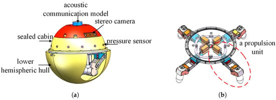
Figure 1.
Structure of the small spherical robot. (a) Mechanical structure of the small spherical robot. (b) Mechanical structure of the vector propulsion mechanism.

Table 1.
Technical parameters of the robot.
2.2. “X”-Shaped Motion Mode of the Underwater Small Spherical Robot
The vector propulsion mechanism is consist of four same propulsion units as shown in Figure 2. Each propulsion unit owns a hip, knee, and ankle joint. As a result, the vector propulsion is very flexible. According to the distribution of four propulsion units, there are “H”-shaped mode and “X”-shaped mode, as shown in Figure 3. Compared to the “H”-shaped mode, “X”-shaped mode is able to overcome current disturbances created by other robots and ensure precise position control. Relationship between the distribution of propulsion forces and the motion direction in the “X”-shaped mode is depicted in Figure 4. The blue lines represent the direction of a propulsion force and the purple lines denote the motion direction.
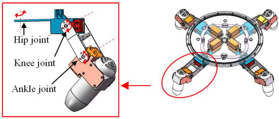
Figure 2.
Mechanism of a propulsion unit.

Figure 3.
Different motion modes of the small spherical robot. (a) “H”-shaped motion mode. (b) “X”-shaped motion mode.
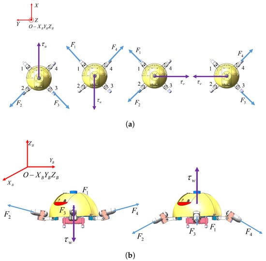
Figure 4.
Distribution of propulsion forces and the motion direction in the “X”-shaped mode. (a) Top view. (b) Side view.
3. Position-Based Coordinated Formation Mechanism
With a clear understanding of the underwater small spherical robot system, it is essential to explore an effective formation mechanism. Thus, this paper proposes a position-based coordinated formation mechanism. The proposed formation mechanism operates on two key principles: (1) planning all desired positions for each robot in the multi-robot spherical system, and (2) employing a control scheme to drive all robots toward their respective reference positions. Firstly, the virtual linkage strategy is adopted to get the desired target positions of each robot according to the formation mission points and the formation shape setting. However, the formation mission points are highly discrete in actual tasks. If spherical robots directly adopt a point-tracking controller to follow a series of desired target points, the following three unexpected situations may occur: (1) Collisions may occur between different robots; (2) Robots may collide with obstacles scattered between two desired points; (3) Due to external disturbances, a robot may deviate significantly from the target point, which results in communication failure between two robots. Similarly, when the formation pattern needs to be changed, the desired target point of each robot may undergoes sudden transition, which may also lead to the occurrence of the aforementioned situations. To avoid the above unexpected situations, it is necessary to generate denser local path points between adjacent desired target points for each robot. Therefore, artificial potential field method and consensus-based method are combined to plan the local positions. As the existing coordinated formations based on these two algorithms mostly generate desired velocities, these two methods are improved to generate local path points in this paper. Finally, each small spherical robot tracks all the planning positions based on active disturbance rejection control (ADRC) to finish formation task. The scheme of the proposed formation mechanism is depicted in Figure 5.
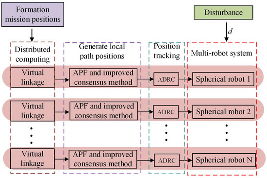
Figure 5.
Position-based coordinated formation mechanism.
3.1. Formation Scheme Based on Virtual Linkage Strategy
3.1.1. Mathematical Model of the Virtual Linkage
Figure 6 illustrates the geometric model of a virtual linkage structure with n virtual linkages and virtual joints. The virtual leader joint named as base is set according to the practical application demand, denoted as . With the virtual leader joint as the boundary, the virtual linkage structure is divided into a left virtual linkage structure and a right virtual linkage structure. A world coordinate system is defined as in Figure 6. indicates the virtual leader joint coordinate system. The red dashed line represents the angle bisector between the planar projections of the left and right virtual linkage structures and is parallel to the axis of the virtual leader joint coordinate system. axis points to the earth. The angle between the extension of linkage i and linkage is defined as . The angle between a linkage and the horizontal plane is defined as . The mathematical model of the virtual linkage structure is defined as:
where, represents the position matrix of the virtual linkage structure. and denote the azimuth vectors. is the length vector of the virtual linkages. The description of the ith linkage is denoted as:
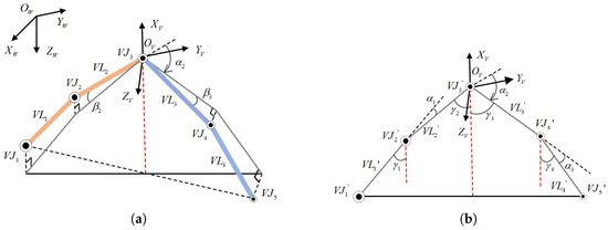
Figure 6.
Geometric model of a virtual linkage structure. (a) Three-dimensional model. (b) Planar Projection.
3.1.2. Position of the Left Virtual Linkage Structure
Left linkages are referred as the left from the virtual leader, denoted as . Joints of left linkages are denoted as . The angle between the horizontal projection of the virtual linkage i and is denoted as . According to the Figure 6, the angles of the left virtual linkages follow the following rule:
To abbreviate the above expression as:
Positions of left virtual joints can be derived as:
3.1.3. Position of the Right Virtual Linkage Structure
Right linkages are referred as the right from the virtual leader, and is denoted as . Joints of right linkages are denoted as . According to the Figure 6, the angles of the right virtual linkages follow the following rule:
To abbreviate the above expression as:
Positions of right virtual joints can be derived as:
3.1.4. Formation Mechanism Based on the Virtual Linkage
There are a series of formation mission points which are set according to the practical mission. The formation system needs to pass through all the points. In the inertial coordinate system, the position coordinates of a formation mission point numbered are denoted as . The formation mission points are set as the virtual leader joint. Therefore, positions of the other virtual joints can be derived according to the following Equation.
where, , which is obtained by Equations (5) and (8). represents the mission point position of the ith robot. is the transformation matrix from the virtual leader joint coordinate system to the inertial coordinate system.
The concrete definition of the can be found in our previous work [21].
3.2. Local Position Planning Strategy Based on Artificial Potential Field and Improved Consensus Method
According to Equation (9), a series of formation desired target points for each individual spherical robot can be obtained. Next step is to plan the local positions between any two desired target points.
For convenience, the following definitions are set. The process of spherical robots approaching each formation desired target point is called the asymptotic process. The asymptotic process between the and the formation desired points is defined as the index-asymptotic-process. The artificial potential field method and improved consensus method are used to generate local path points during the asymptotic process. Positions of the robot i is denoted . It is assumed that the robot is in the asymptotic process of tracking the formation desired target point . Asymptotic reference points during the index-asymptotic-process are labeled as . For clarity, the following explanations are listed. (1) The formation mission points are set according to the actual mission requirements. In cases where the mission involves encircling and capturing a sensitive target, the position of the sensitive target serves as the formation mission point. The formation desired target points for each robot are generated by the above virtual linkage strategy. (2) The asymptotic reference points which are actually tracked by the robots are locally planned reference points that are generated based on the improved consensus and artificial potential field algorithms. The asymptotic reference points are updated step by step by the following equation.
where, is the th asymptotic reference point of the robot i. represent the expected movement step lengths calculated based on the improved consensus and the artificial potential field method respectively. are the gain coefficients.
3.2.1. The Local Point Planning Based on Artificial Potential Field
The key issue in the artificial potential field method is designing appropriate potential field functions. Since robots need to avoid collisions with adjacent robots and obstacles in the environment during the asymptotic process, appropriate potential field functions are need to be set. The potential field function utilized to avoid collision between robots is designed as the following.
Equation (12) represents the potential function when the robot i is in the repulsive force field of robot j. Where, is the coefficient of repulsive force field intensity. R is the radius of the spherical robot. is the range of the repulsive force field. is the euclidean distance between the two robots. The repulsive force exerted on robot i within the repulsive force field of robot j can be obtained by taking the gradient of the Equation (12).
where, represents the positive direction of the repulsive force. When the formation shape is set, the length of the edge formed by two adjacent robots should be greater than the repulsive force field range to avoid any impact of the repulsive force field on the formation shape. The potential field function (12) can also be adopted for obstacle avoidance. However, when the distance between the formation reference point and an obstacle is relatively small, a goal unreachable issue may occur. For this reason, the distance between the formation reference point and the obstacle is considered in the following potential field function.
where, is the coefficient of repulsive force field intensity. is the radius of the circumscribed circle of the obstacle. is the range of repulsive force field generated by the obstacle. is the the euclidean distance between the robot and the obstacle. represents the distance from the robot to the corresponding formation reference point. , m can be set according to the distance between the robot and the corresponding formation reference point. When the robot is relatively close to the formation reference point, m is set to a larger value. The repulsive force from the obstacle is obtained by computing the gradient of the Equation (14), shown as following.
where, represents the positive direction of the repulsive force generated by the obstacle. When the distance between the robot and the corresponding formation reference point is almost zero, the repulsive force from the obstacle also tends to zero.
Based on the comprehensive analysis mentioned above, the in Equation (11) is represented as follows:
where, , N is the number of all spherical robots. is the position of the obstacle k. , is the number of all obstacles.
3.2.2. The Local Point Planning Based on the Improved Consensus
The model of a first-order system as following is considered.
where, n is the number of the spherical robots; represents the states vector; is the control input of the spherical robot i. The first-order consensus algorithm can be described as follows:
When the above algorithm is adopted, the states of the spherical robot i converge to the states of the adjacent spherical robot j. Equation (17) is substituted into Equation (18), and the following matrix representation is obtained.
where, m is the dimensions of the spherical robot states; is a vector which is compose of all state vector. is the Laplacian matrix of the directed graph .
The consensus of the formation system means that for any initial state , as , . The sufficient and necessary condition for the multi-robot system converging to consensus by adopting the consensus algorithm (17) is that the graph G owns a directed spanning tree. The proof can be found in reference [22] and is not repeated here.
According to the perspective of consensus algorithms, the most effective formation control involves creating a specified position deviation between any two robots, and then ensures that the entire system maintains a particular formation. For this purpose, the traditional consensus algorithm (18) is improved. , the position of the spherical robot i, is set as state value. The relative position deviation between two adjacent spherical robots is expected to reach a desired value, and that is . denotes the desired position deviation. The desired positions of the n spherical robots, , are predefined in order to guarantee the formation shape of the multi-robot system. The desired position deviation is defined as . When is taken as the system state and applied to the consensus algorithm (18), the following equation can be obtained:
The multi-robot system can achieve different formation shape by defining different . When is a constant, , which denotes that the formation shape has been formed and maintained.
Based on the above analysis, the local position point planning method based on improved consensus is defined as following.
where, the first term on the right side is the tracking term, and the second term is the convergence term. denote the current positions of the robots; is the desired position at the next time step. in Equation (11) is written as .
The local position planning method combining artificial potential field and improved consensus is shown in Algorithm 1.
| Algorithm 1 The local position planning method combining the artificial potential field and the improved consensus |
|
3.3. Active Disturbance Rejection-Based Position Tracking Control Law
Based on the above analysis, a series of tracking points for each spherical robot is obtained. In order to achieve the formation mission, a point tracking controller is essential. Active disturbance rejection controller (ADRC) is able to observes internal uncertainties and external disturbances through Extended State Observer (ESO), and then quickly compensate for interference [23]. Since there is no completely undisturbed still water environment in practical applications, this paper utilizes ADRC to accomplish the point tracking. For the spherical robot maintaining the X-shaped motion mode, the point tracking control framework in the three-dimensional space is illustrated in Figure 7. The frame divides the point tracking control into three independent degrees of freedom, specifically surge, sway, and heavy. For this purpose, three ADRCs are designed for position tracking along these three degrees of freedom.
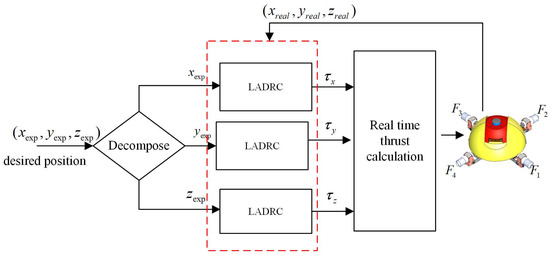
Figure 7.
Position-based tracking control framework.
Because the research on formation algorithms for spherical multi-robots is oriented towards practical applications, the complexity of the controller must be considered along with ensuring control effectiveness during the controller design phase. Therefore, a linear active disturbance rejection controller (LADRC) is adopted in this paper. Traditionally, ADRC is consist of three main components: the tracking differentiator (TD), the extended state observer (ESO), and the nonlinear state error feedback (NLSEF) [24]. Subsequently, the three components of ADRC are designed for the point tracking in surge degree of freedom.
The primary role of TD is to overcome noise disturbance for extracting the input signal. The input of the ADRC for point tracking is the current position of the spherical robot, denoted as . The TD divide into two signals, namely and . , a position value, is the tracking value at the time step k during the transition process. is the derivative value of at the time step k, and represents a velocity value. and can be updated based on the following expression.
where, T is the sampling time. h is a filtering factor used to filter the input signal. is a speed factor that influences the tracking speed.
The ESO redefines the sum of all uncertain terms in the system as a new state variable and estimates the value of this new state. The estimated values of all uncertain terms are then added to the feedback loop as compensation. The dynamic model of the spherical in surge degree of freedom is written as the following [21].
Given , the linear discrete-time second-order extended state observer is written as:
where, are observer gains. b is the controller gain.
The state error feedback controller primarily counteracts disturbances and eliminates the output error of the TD and ESO. The state error feedback controller essentially functions as a proportional-derivative (PD) controller for the linear active disturbance rejection control (LADRC). The error compensation controller is designed as the following.
where, is the x coordinate of the tracking point position. are controller gains. is the control input of the spherical robot in surge degree of freedom.
The ADRC designing for other degrees of freedom are similar to the above designing and will not be elaborated here.
4. Simulation Results
The process of spherical robots tracking the first formation mission point is defined as the first asymptotic process that is the process of forming the formation shape. After that, tracking other task points involves similar asymptotic processes. Therefore, the phase of forming the formation shape is the focus of the formation mission. For this purpose, the following simulation is carried out. As the spherical robot is in the X-motion mode, the surge, sway and heavy degree of freedom are fully decoupled. For observing the results more clearly, a series of simulations firstly were conducted on a two-dimensional plane to verify the effectiveness of the local point planning strategy based on APF and improved consensus algorithm. Finally, a comprehensive simulation was carried out for multi-spherical robot formation in a complex three-dimensional environment.
4.1. Parameters Setting for Simulations
All the simulations were conducted using MATLAB 2015a on a Windows 7 platform with an Intel Core i7-4790 processor (3.6 GHz base frequency) and 8 GB of RAM. Considering three obstacles and a multi-spherical robot system with three agents, the parameters are predefined hereafter. Diameter of the robot is set as m consistent with that of the actual robot. Range of the robot repulsive force is m. Diameter of obstacles is set as m, and range of the repulsive force is set as 1 m. Parameters of the ADRC are set as: , = 10,000 in Equation (22), in Equation (22), in Equation (23), in Equation (24) , in Equation (25) . The adjacent matrix is set as following.
4.2. Verification of the Improved Consensus Algorithm for Local Point Planning
In order to verify the effectiveness of the improved consensus algorithm, a straight-line formation mission for a multi-robot system with three agents is set. The initial positions of three robots are defined as . Setting of the formation shape is . One simulation is that the tracking points of three robots are computed only based on the virtual linkage. In the contrast simulation, besides using the virtual linkage strategy to calculate the formation desired target points for three robots, the improved consensus algorithm is also employed to compute the local points of the next step for each robot during each asymptotic process. To enhance the contrast effect during the formation process, the positions of robot 1 and robot 2 are forcibly moved to other points to simulate unexpected environmental disturbances. The simulation result is shown in Figure 8. In the simulation, the position of robot 1 is forcibly moved from (10, 8) to (10, 25), and the position of robot 2 is forcibly moved from (10, 10) to (6, 20). Seen from the black dashed box section in the diagram, when robot 1 and robot 2 are disturbed, the trajectory of robot 3 adopting the improved consensus algorithm changes. The main reason is that under the constraint of the consensus algorithm, robot 3 adjusts the position of itself to avoid excessive distances between any two robots, which could affect the formation. While, formation strategy only based on virtual linkage lead to no change of the trajectory for robot, when robot 1 and robot 2 are suddenly disturbed. According to the simulation result in Figure 8, three robots adopting two different formation strategies all achieve ling-straight formation. However, in practical applications, excessive distances between robots may affect the communication, which impacts the formation task. Based on the above analysis, it can be proven that the local point planning method based on the improved consensus algorithm for multiple robot formation is effective and has advantages for practical applications.
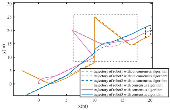
Figure 8.
Line formation for multiple spherical robots to verify the effectiveness of the improved consensus algorithm.
4.3. Verification of the APF for Local Point Planning
4.3.1. Avoiding Collision Among Robots
To verify that the collision avoidance method based on the designed APF can effectively prevent collisions between robots, the following simulation is designed. Three robots need to form a line shape formation at the point . The initial positions and the setting of the formation shape are the same with that in the above simulation. Figure 9 shows the trajectories of three robots during the formation process. As shown in the figure, all robots can converge to the respective formation desired target points, and the formation task is accomplished. While, the trajectories depicted in Figure 9a are more complex compared to those in Figure 9b, which is led to by the collision avoidance. Distances between any two robots during the formation process are illustrated in Figure 10. The dashed black line denotes the safe distance of any two robots in Figure 10a. It can be seen that under the influence of the repulsive force fields of adjacent robots, three robots can form the formation while maintaining a safe distance constraint. However, in Figure 10b, the distance between robot 1 and robot 3 is zero at s, and the distance between robot 2 and robot 3 is zero at s, which means that there are two collisions during the formation process.
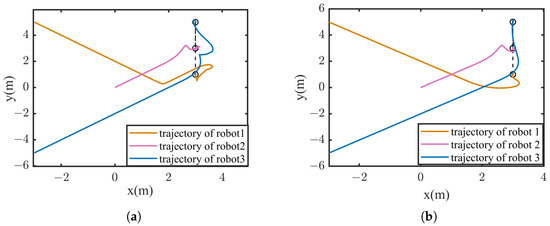
Figure 9.
Trajectory of the robots in the line shape formation to verify the effectiveness of APF for the collision avoidance. (a) situation with collision avoidance. (b) situation without collision avoidance.
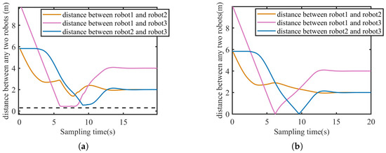
Figure 10.
Distance between any two robots in the line shape formation to verify the effectiveness of APF for the collision avoidance. (a) Situation with collision avoidance. (b) Situation without collision avoidance.
When the safe distance between robots is disregarded, the motion trajectories of robots during the formation process are simpler. However, in this process, collisions between robots may occur, which would mean the failure of the formation and could even cause more serious losses in practical applications. Therefore, the design of a collision avoidance function based on APF is both effective and necessary.
4.3.2. Avoiding Obstacles
In order to verify the effectiveness of the APF for obstacle avoidance, three obstacles are set in the simulation environment. Positions of the obstacles are set as: , , . Settings of initial positions, formation setup, and formation task for three robots are the same as that in the above subsection. The simulation result is shown in Figure 11. Figure 11a depicts that three robots can avoid the obstacles and converge to the respective desired positions, then finally form the straight-line formation. Seen from the Figure 11b, the distances between any two robots are greater than the safety distance, which is the reason of considering obstacles avoidance and collision avoidance among robots. The simulation results prove the effectiveness of the designed APF on obstacle avoidance.
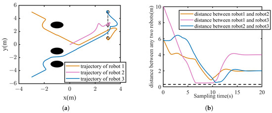
Figure 11.
Line formation of multi-spherical robots in the environment with obstacles to verify the effectiveness of APF for the obstacle avoidance. (a) Trajectories of the three robots. (b) Distances between any two robots.
When the desired tracking point of the robot is within the repulsive range of an obstacle, the robot may be prevented from reaching the desired tracking point due to the repulsive force of the obstacle, which will lead to formation failure. For this purpose, the distance between the robot and the target position is added as a coefficient to the traditional potential field function. To verify the superiority of the improved potential field function for obstacle avoidance, the following simulation is designed. Three obstacles are set, and the positions are set as: , , . Position of the formation mission is . Setting of the formation shape is consistent with that in the above simulation. In the simulation, when the distance between the robot and the target position is less than 1, m is set to 5 in Equation (15); otherwise, m is set to 0. Trajectories of the three robots based on the traditional potential field function are shown in Figure 12b. The dashed red line represents the range of the obstacle repulsive force. As can be seen from the partially enlarged view, robot 3 reaches the desired tracking point, while robot 1 experiences oscillation due to the repulsive force field of the obstacle. Although robot 2 is not within the repulsive force field of the obstacle, robot 2 is influenced by the position of robot 1 because of the consensus algorithm, and also fails to accurately converge to the target point. Figure 12a depicts that the trajectories of the robots based on the improved APF are able to avoid the obstacles and converge to the desired positions. When the robot is in the range of the repulsive force field of an obstacle and approaching the target tracking point, the distance term between the robot and the target point becomes a very small proportional coefficient to reduce the influence of the repulsive force on the robot, which enables the robot to converge to the desired point.
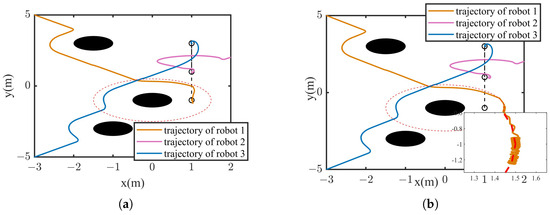
Figure 12.
Trajectories of the robots during the Line formation process in the environment with obstacles based on APF with different potential field functions. (a) Trajectories based on APF with improved potential field function. (b) Trajectories based on APF with traditional potential field function.
4.4. Three-Dimensional Formation of Multiple Spherical Robots
Two simulations are carried out in this subsection further to verify the effectiveness of the proposed formation mechanism based on the virtual linkage strategy and point tracking algorithm. One simulation is the three-dimensional formation for multi-spherical robot system in the environment with obstacles. The other is that the formation transformation and tracking in a three-dimensional environment.
4.4.1. Three-Dimensional Formation of Multi-Spherical Robot System in the Complex Environment
It is assumed that there are three obstacles in the environment. The radius of all obstacles is set to m. The radius of the repulsive force range is m. The center position of the obstacles are , , , respectively. The formation mission is forming a triangle formation with three robots. Initial positions of the robots and setting of the formation shape are listed as follows:
In the simulation, five formation target points are setting. The position of the first mission point is set to . The x and y coordinates of the other task points are set with equal intervals of 1.4, and the z coordinate is set at equal intervals of −0.7. The motion trajectories of three robots are shown in Figure 13. The triangles formed by dashed lines in the diagram represent the formation task target points. As shown in the Figure 13, the robots can avoid all obstacles and form a triangular formation at the designated target points. The point tracking errors of the robots at the five formation target points are listed in Table 2. The x coordinate error of the robot 2 is a little great, which is caused by obstacles near the third task point. When there are no obstacles near the formation target points, the point tracking error is almost 0, and the robots form the desired formation. The distances of any two robots are depicted in the Figure 14. The dashed line indicates the safety distance between any two robots to prevent collisions. It is observed that during the formation process, the distances between robots remain within a safe range. Based on the above analysis, it is proven that the formation mechanism proposed in this paper can achieve formation for multi-spherical robots in three-dimensional environment, and can safely avoid obstacles during the formation process.
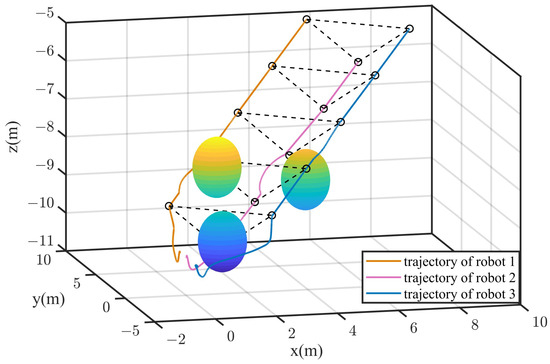
Figure 13.
Formation based on the proposed formation mechanism in the complex three-dimensional environment.

Table 2.
Root mean square errors during the triangle formation process.
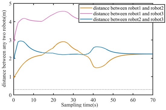
Figure 14.
Distance between any two robots during the process of formation in the complex three-dimensional environment.
4.4.2. Formation Transformation of Multiple Spherical Robots in the Three-Dimensional Environment
To verify that the proposed virtual linkage formation strategy can flexibly change formation shape among multi-spherical robots, a simulation for formation transformation is designed. Settings of the formation shapes and the transformation process are described in Figure 15. The initial positions of three robots are consist with that in the above section. The simulation results are shown in Figure 16 and Figure 17. Figure 16 depicts the trajectories of three robots during the whole formation process. The red solid line represents the virtual linkage structure formed between the two robots. The robot 2 is located at the base joint of the virtual linkage. It is observed that three robots achieve the formation mission and formation transformation. The distances between any two robots are shown in Figure 17. It can be found that the distances between any two robots are greater than the safe distance, which means that there is no collision during the whole process. According to the above analysis, the virtual linkage formation strategy with the improved consensus and APF can achieve flexible and smooth formation switching, which makes the formation mechanism for multi-spherical robot system more practically significant.

Figure 15.
Diagram of the formation transformation in the three-dimensional environment.
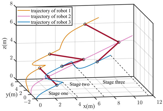
Figure 16.
Formation transformation of multi-spherical robot system in the three-dimensional environment.
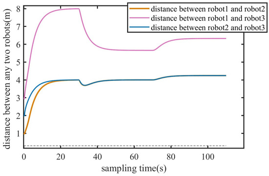
Figure 17.
Distance between any two robots during formation transformation in the three-dimensional environment.
5. Experimental Results and Analysis
The proposed formation mechanism was deployed on two spherical robots. An experiment was conducted to verify and evaluate the proposed formation strategy.
5.1. Experiment Setting
The experiment was carried out in a indoor pool with the dimension of 3.5 m × 2.5 m × 1 m (length × width × height). The framework of the multi-spherical robot formation system mainly consists of a global positioning system based on the Jetson NANO, two small spherical robots, a wireless AP/router, and a ground control station. The Jetson NANO system installed on a shelf at a high position adopts a down looking camera to identify and locate the spherical robots, as well as to monitor their surroundings environment, such as obstacle detection. The KCF (Kernel Correlation Filter) is used to recognize and track the spherical robot and then the position information was computed according to the vision knowledge [25]. Then, the position information was wireless transmitted to the ground station through the TCP/IP protocol. The ground station utilized multimaster-fkie (an ROS communication mechanism) to receive or publish robot position and posture information. The process of data transmitting is shown in Figure 18. The two spherical robots used in the experiment are shown in Figure 19. The experimental environment is shown in Figure 20, where a circular red mark indicates the origin of the world coordinate system.
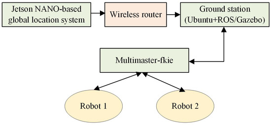
Figure 18.
Process of data transmitting.
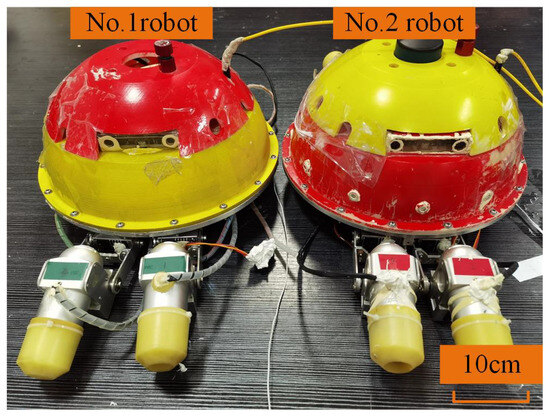
Figure 19.
Two spherical robots used in the experiment.
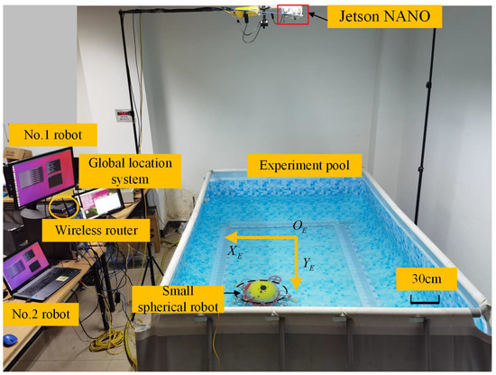
Figure 20.
Experimental environment setup.
5.2. Formation Experiment Result
The formation experiment was carried out to form a straight-line formation with two spherical robots. The setting of the formation shape is set as m. 14 formation mission points are set every m along a line. The experiment result is shown in Figure 21. The points marked by the black circles are the initial locations of the two robots. As it can be seen, the two spherical robots can basically form a straight-line formation, but there are slight oscillations during the process, which are mainly caused by the robots approaching the walls of the experimental pool. The root mean square errors (RMSE) between the real positions and the target points are shown in Table 3. The errors are almost zero. The RMSE of robot 2 in y coordinate is 0.12 m, approximately 12% of the formation size, which satisfies the requirement of the formation error. In addition, the RMS of the real formation shape is also listed in Table 3. The formation error is less than 0.1301 m (0.43BL), accounting for 13% of the formation size, which satisfies the formation error requirement. Based on the analysis of the above experimental results, it can be concluded that the proposed formation method based on the point tracking and virtual linkage strategy can achieve formation task for multiple small spherical robots, which demonstrates the feasibility and effectiveness of the algorithm in practical applications.
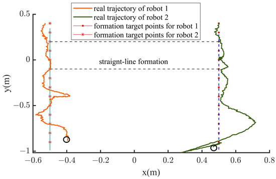
Figure 21.
Trajectories of the two robots during the straight-ling formation experiment based on the proposed mechanism.

Table 3.
Root mean square errors between real and target positions for the straight-line formation.
6. Discussion
This research aims to design a reliable and easy to implement formation scheme for the multi-small spherical robot platform with limited computing and sensing capabilities. Therefore, position-based coordinated formation strategy was designed. In order to obtain all desired positions during the formation process, the virtual linkage, consensus algorithm and APF were integrated. My team designed a virtual linkage-based adaptive formation control strategy for multiple spherical robot system, which emphasized the flexible changing of virtual linkage angle [20]. The formation strategy only based on the virtual linkage is similar to an open loop system. Therefore, the consensus algorithm was applied to avoid the problem in this paper. As we all known, the consensus algorithm is a common formation strategy [12,13]. The traditional consensus algorithm is based on velocity information. However, the small spherical robot is not able to acquire the accurate velocity. To this end, the traditional consensus algorithm was improved by only considering the relative distance between adjacent spherical robots. The APF is usually utilized to realize path planning and obstacle avoiding [17,18]. The APF in this paper was utilized to avoid collision with other robots or obstacles. Therefore, only repulsion was considered. In addition, in order to avoid the problem of unreachable targets, the potential function considering the distance between obstacle and desired target was designed. Through the cooperation of various aspects mentioned above, the position-based formation mechanism proposed in this manuscript is able to be realized.
On the basis of the simulation and experiment analysis in Section 4 and Section 5, the proposed formation mechanism was demonstrated to be feasible and effective for multiple small spherical robots. Especially, the simulation results demonstrated the effectiveness of the improved position-based consensus algorithm, the improved APF and the position-based formation strategy. Due to limited experimental environment and platform, the experiment was relatively rough. However, the experiment results were also able to prove the feasibility. In fact, most of the exiting formation studies for underwater multiple robots are only in the stage of numerical simulation. Therefore, the proposed formation strategy which is easy to deployed for multiple small underwater robots in engineering provides reference for further studies.
Despite the successful implementation of the position-based formation strategy, there are still some limitations. On one hand, this paper places particular emphasis on the reliable and easy to implement formation scheme. In the real experiment, there is no real communication between each two robots. The position information of other robots was obtained by the ground station. This issue may be solved by adopting underwater acoustic communication devices. On the other hand, there are no experiments in real outdoor oceans. This issue will be our further research focus.
7. Conclusions and Future Work
In this paper, the formation mechanism for multiple small spherical robot system was studied. This study aimed at providing a method that is easily deployed in engineering. Therefore, the formation control strategy based on position is proposed. In order to achieve formation and formation shape changing, we design a position planning method for the formation process by integrating a virtual linkage approach with an improved consensus algorithm and artificial potential field techniques. The virtual linkage strategy is in charge of computing the formation desired target positions of robots according to the predefined position of virtual leader joint. The improved consensus and APF algorithms are responsible for planning the local desired positions between two formation desired target positions, which is able to prevent collisions and excessive communication distance between robots. A series of simulations and experiments were conducted to verify the effectiveness of the proposed method. The simulation results showed that formation and formation shape changing without collisions in three dimension space based on the proposed formation mechanism were able to be achieved. In addition, the formation errors almost converged to zero. The formation error in experiment is within 0.1301m (0.43BL), accounting for 13% of the formation size, which satisfies the formation error requirement. Above all, the results prove that the proposed formation mechanism is feasible and effective for multiple small spherical robot system.
However, there are some inadequacies in this paper. Firstly, the communication between two robots is not considered. Positions of the robot are obtained by a global vision system, which leads to the inability to achieving distributed formation control. In the future, a reliable and effective communication needs to be researched and the distributed formation control for multiple small spherical robot system will be implemented. Secondly, we will conduct research on multi-spherical robot formation assisted by a quadrotor to achieve cross domain collaborative formation in real ocean environment.
Author Contributions
Methodology, writing, and editing, X.H.; Software and visualization, Z.L.and H.S. Supervision, S.G., review and investigation, N.Y. and H.X.; Funding acquisition, X.H. All authors have read and agreed to the published version of the manuscript.
Funding
This research was funded by Science Research Project of Hebei Education Department (BJK2023064) and Doctor Innovation Project of Tangshan University (BC202213).
Institutional Review Board Statement
Not applicable.
Informed Consent Statement
Not applicable.
Data Availability Statement
Data is contained within the article.
Conflicts of Interest
Author Zan Li was employed by the company Cai Hong Unmanned Aerial Vehicle. The remaining authors declare that the research was conducted in the absence of any commercial or financial relationships that could be construed as a potential conflict of interest.
References
- Dai, S.; Wu, Z.; Zhang, P.; Tan, M.; Yu, J. Distributed Formation Control for a Multirobotic Fish System with Model-Based Event-Triggered Communication Mechanism. IEEE Trans. Ind. Electron. 2023, 70, 11433–11442. [Google Scholar] [CrossRef]
- Zhou, Z.; Liu, J.; Yu, J. A Survey of Underwater Multi-Robot Systems. IEEE/CAA J. Autom. Sin. 2022, 9, 1–18. [Google Scholar] [CrossRef]
- Elmokadem, T.; Zribi, M.; Youcef-Toumi, K. Control for Dynamic Positioning and Way-point Tracking of Underactuated Autonomous Underwater Vehicles Using Sliding Mode Control. J. Intell. Robot. Syst. 2018, 95, 1113–1132. [Google Scholar] [CrossRef]
- Guo, J.; Liu, Z.; Song, Y.; Yang, C.; Liang, C. Research on Multi-UAV Formation and Semi-Physical Simulation with Virtual Structure. IEEE Access 2023, 11, 126027–126039. [Google Scholar] [CrossRef]
- He, S.; Wang, M.; Dai, S.L.; Luo, F. Leader-Follower Formation Control of USVs with Prescribed Performance and Collision Avoidance. IEEE Trans. Ind. Inform. 2018, 15, 572–581. [Google Scholar] [CrossRef]
- Rani, M.; Kumar, N. A neural network based efficient leader–follower formation control approach for multiple autonomous underwater vehicles. Eng. Appl. Artif. Intell. 2023, 122, 106102. [Google Scholar] [CrossRef]
- Wang, J.; Wang, C.; Wei, Y.; Zhang, C. Sliding mode based neural adaptive formation control of underactuated AUVs with leader-follower strategy. Appl. Ocean. Res. 2020, 94, 101971. [Google Scholar] [CrossRef]
- Tan, K.H.; Lewis, M.A. Virtual structures for high-precision cooperative mobile robotic control. In Proceedings of the IEEE/RSJ International Conference on Intelligent Robots and Systems, Osaka, Japan, 8 November 1996; Volume 1, pp. 132–139. [Google Scholar]
- Heshmati-alamdari, S.; Karras, G.C.; Kyriakopoulos, K.J. A Distributed Predictive Control Approach for Cooperative Manipulation of Multiple Underwater Vehicle Manipulator Systems. In Proceedings of the 2019 International Conference on Robotics and Automation (ICRA), Montreal, QC, Canada, 20–24 May 2019; pp. 4626–4632. [Google Scholar]
- Yan, X.; Jiang, D.; Miao, R.; Li, Y. Formation Control and Obstacle Avoidance Algorithm of a Multi-USV System Based on Virtual Structure and Artificial Potential Field. J. Mar. Sci. Eng. 2021, 9, 161. [Google Scholar] [CrossRef]
- Pan, W.; Jiang, D.; Pang, Y.; Qi, Y.; Luo, D. Distributed Formation Control of Autonomous Underwater Vehicles Based on Flocking and Consensus Algorithms. In Proceedings of the International Conference on Intelligent Robotics and Applications, Wuhan, China, 16–18 August 2017. [Google Scholar]
- Yan, T.; Xu, Z.; Yang, S.X. Consensus Formation Tracking for Multiple AUV Systems Using Distributed Bioinspired Sliding Mode Control. IEEE Trans. Intell. Veh. 2023, 8, 1081–1092. [Google Scholar] [CrossRef]
- Mokhtari, M.; Taghizadeh, M.; Mazare, M. Distributed consensus and formation control of multi-AUV systems under actuator faults and switching topology. Eur. J. Control 2024, 79, 101006. [Google Scholar] [CrossRef]
- Zhang, J.; Sha, J.; Han, G.; Liu, J.; Qian, Y. A Cooperative-Control-Based Underwater Target Escorting Mechanism with Multiple Autonomous Underwater Vehicles for Underwater Internet of Things. IEEE Internet Things J. 2020, 8, 4403–4416. [Google Scholar] [CrossRef]
- Xia, G.; Zhang, Y.; Yang, Y. Control Method of Multi-AUV Circular Formation Combining Consensus Theory and Artificial Potential Field Method. In Proceedings of the 2020 Chinese Control And Decision Conference (CCDC), Hefei, China, 22–24 August 2020; pp. 3055–3061. [Google Scholar] [CrossRef]
- Zhen, Q.; Wan, L.; Zhang, Y.; Jiang, D. Consensus-Based Formation Control and Gyroscopic Obstacle Avoidance for Multiple Autonomous Underwater Vehicles on SE(3). J. Mar. Sci. Eng. 2024, 12, 2350. [Google Scholar] [CrossRef]
- Hao, K.; Zhao, J.; Li, Z.; Liu, Y.L.; Zhao, L. Dynamic path planning of a three-dimensional underwater AUV based on an adaptive genetic algorithm. Ocean. Eng. 2022, 263, 112421. [Google Scholar] [CrossRef]
- Fan, X.; Guo, Y.; Liu, H.; Wei, B.; Lyu, W. Improved Artificial Potential Field Method Applied for AUV Path Planning. Math. Probl. Eng. 2020, 2020, 1–21. [Google Scholar] [CrossRef]
- Liu, Y.; Gao, J.; Liu, C.; Zhao, F.; Zhao, J. Reconfigurable Formation Control of Multi-Agents Using Virtual Linkage Approach. Appl. Sci. 2018, 8, 1109. [Google Scholar] [CrossRef]
- Yin, H.; Guo, S.; Liu, M. A Virtual Linkage-Based Dual Event-Triggered Formation Control Strategy for Multiple Amphibious Spherical Robots in Constrained Space with Limited Communication. IEEE Sens. J. 2022, 22, 13395–13406. [Google Scholar] [CrossRef]
- Hou, X.; Xing, H.; Guo, S.; Shi, H.; Yuan, N. Design and Implementation of a Model Predictive Formation Tracking Control System for Underwater Multiple Small Spherical Robots. Appl. Sci. 2024, 14, 294. [Google Scholar] [CrossRef]
- Wang, J.; Hu, X. Distributed Consensus in Multi-vehicle Cooperative Control: Theory and Applications. IEEE Control Syst. Mag. 2010, 30, 85–86. [Google Scholar]
- Li, A.; Guo, S.; Li, C. An Improved Motion Strategy with Uncertainty Perception for the Underwater Robot Based on Thrust Allocation Model. IEEE Robot. Autom. Lett. 2025, 10, 64–71. [Google Scholar] [CrossRef]
- Han, J. From PID to Active Disturbance Rejection Control. IEEE Trans. Ind. Electron. 2009, 56, 900–906. [Google Scholar] [CrossRef]
- Xing, H.; Guo, S.; Shi, L.; He, Y.; Su, S.; Chen, Z.; Hou, X. Hybrid Locomotion Evaluation for a Novel Amphibious Spherical Robot. Appl. Sci. 2018, 8, 156. [Google Scholar] [CrossRef]
Disclaimer/Publisher’s Note: The statements, opinions and data contained in all publications are solely those of the individual author(s) and contributor(s) and not of MDPI and/or the editor(s). MDPI and/or the editor(s) disclaim responsibility for any injury to people or property resulting from any ideas, methods, instructions or products referred to in the content. |
© 2025 by the authors. Licensee MDPI, Basel, Switzerland. This article is an open access article distributed under the terms and conditions of the Creative Commons Attribution (CC BY) license (https://creativecommons.org/licenses/by/4.0/).