1. Introduction
Lower-limb amputation substantially alters human locomotion by replacing biological segments with artificial components that differ in mass distribution, mechanical properties, and control strategies. Individuals with transfemoral amputation are particularly affected, as the loss of the knee joint and surrounding musculature leads to pronounced compensatory strategies during gait and increased reliance on the prosthetic limb for support and stability [
1,
2]. Despite continuous advances in prosthetic component design, discomfort, residual limb pain, and skin breakdown remain common clinical challenges, often limiting long-term prosthesis use and mobility outcomes [
3,
4,
5].
A critical factor underlying these complications is the mechanical interaction between the prosthesis and the residual limb, which occurs primarily at the socket interface. Excessive axial and shear loads transmitted through the socket have been associated with soft tissue irritation, pressure-related injuries, and long-term musculoskeletal overuse [
6,
7,
8]. However, direct in vivo measurement of internal forces at the socket–residual limb interface remains technically unfeasible during dynamic activities such as walking. As a result, clinical prosthesis optimization is still largely guided by practitioner experience, visual gait assessment, and subjective user feedback, particularly when selecting component mass, alignment, and configuration [
9].
Experimental gait analysis has significantly improved the objective characterization of prosthetic gait by providing detailed kinematic and kinetic measurements, including ground reaction forces (GRF) and joint moments [
10,
11]. While these measurements are invaluable for describing external loading and movement patterns, they do not directly reveal internal joints or socket-level forces. Moreover, invasive instrumented prostheses capable of measuring internal loads are limited to highly specialized research settings and are not suitable for routine clinical application [
12].
Digital musculoskeletal modeling has emerged as a powerful tool to bridge this gap by integrating experimental gait data with biomechanically consistent representations of the human–prosthesis system. Frameworks such as OpenSim enable the computation of constraint force transmission quantities [
13,
14,
15]. In prosthetic gait research, JRF can be used as a model-based measure of constraint force transmission across joints and prosthetic junctions, particularly in comparative mechanistic analyses [
16,
17]. Previous studies have demonstrated the sensitivity of JRF to modeling assumptions, prosthesis configuration, and subject-specific parameters, highlighting their value for mechanistic investigation of prosthesis design effects [
18,
19].
Among prosthesis design parameters, component mass, mass distribution (inertia), and alignment are routinely adjusted in clinical practice and are frequently cited by users as factors influencing comfort and perceived effort [
20,
21,
22]. Nevertheless, quantitative evidence explaining how these parameters independently affect modeled force transmission across prosthetic junctions during gait remains limited. Many prior studies have focused on population-level comparisons or have altered multiple parameters simultaneously, making it difficult to isolate the mechanical contribution of individual design variables [
23]. This has led to diverging hypotheses regarding the biomechanical relevance of prosthesis mass, with some studies reporting negligible effects on gait kinetics, while others suggest substantial increases in mechanical demand and metabolic cost [
24,
25].
The present study addresses this gap by employing a digital musculoskeletal model with an integrated transfemoral prosthesis to perform a controlled sensitivity analysis of key prosthesis parameters. By systematically modifying prosthesis mass, inertia, and mediolateral alignment one parameter at a time while maintaining identical kinematics and external loading conditions, the model isolates the first-order mechanical contribution of each parameter to predicted constraint reaction forces. Rather than aiming for clinical generalization, the focus of this work is a proof-of-concept mechanistic framework: identifying how prosthesis design parameters rank in their influence on constraint force transmission across the socket-level junction and prosthetic ankle under fixed gait inputs.
The findings of this study provide quantitative insight into the relative mechanical sensitivity of common prosthesis design decisions within a controlled modeling framework. Rather than providing direct clinical guidance, the study demonstrates how fixed-input musculoskeletal simulations can be used to rank the influence of mass, inertia, and alignment on predicted constraint force transmission across prosthetic junctions.
2. Materials and Methods
2.1. Study Design and Overview
This study was designed as a computational musculoskeletal modeling investigation aimed at quantifying the mechanical sensitivity of constraint reactions to key prosthesis design parameters. Rather than performing clinical validation or population-level comparisons, the focus was placed on a controlled, mechanistic analysis using a single individualized digital model as a biomechanical testbench. Kinematic trajectories and ground reaction forces were derived from a healthy reference subject and were intentionally used to provide consistent, controlled inputs for parameter isolation.
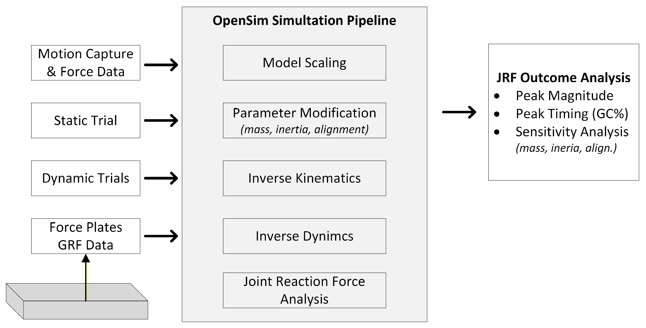
A transfemoral prosthesis was integrated into a standard lower-limb musculoskeletal model, and experimentally measured gait data were used to provide consistent kinematic and external loading inputs. Prosthesis mass, inertial properties, and mediolateral alignment were systematically modified using a one-factor-at-a-time design, while joint kinematics and ground reaction forces were kept identical across all simulation conditions. This design allowed differences in predicted constraint reaction forces to be attributed primarily to changes in mechanical parameters, rather than to differences in gait kinematics or external loading. The overall modeling workflow is illustrated in
Figure 1.
The primary outcome measures were joint reaction forces at the prosthetic socket-level junction and prosthetic ankle, analyzed over the gait cycle and normalized to body weight. Gait cycle events were identified from the vertical ground reaction force (GRF) signals recorded by the force plates. Initial contact (heel strike) was defined as the instant when vertical GRF exceeded a 20 N threshold, and the gait cycle was defined from one heel strike to the subsequent ipsilateral heel strike. All kinematic and kinetic variables were time-normalized to 0–100% of the gait cycle prior to analysis.
In the present study, joint reaction forces are interpreted as model-based constraint reactions describing force transmission across prosthetic junctions under prescribed gait inputs rather than as physiological joint contact forces. Normalization to body weight was used to facilitate relative comparison across conditions and to characterize the magnitude of predicted constraint force transmission. By isolating mechanical parameter effects, this study aimed to establish a sensitivity ranking and relative changes across conditions to identify which prosthesis design parameters most strongly influence predicted constraint force transmission under fixed gait inputs and which exhibit limited biomechanical impact. Accordingly, the reported sensitivities should be interpreted as specific to the imposed kinematic regime and not as subject-independent estimates of how transfemoral prosthesis users would respond to the same parameter changes.
2.2. Experimental Gait Data and Reference Subject
Experimental gait data from a healthy adult subject (body mass: 72 kg, height: 180 cm) were used as reference inputs for musculoskeletal model scaling and dynamic analyses. The reference dataset was used to provide consistent motion patterns and external loading conditions for the computational analysis, rather than to represent the gait of a transfemoral prosthesis user. This choice was made to enable controlled parameter isolation, but it also means that the resulting force sensitivities are conditional on a non-amputee kinematic input and may differ substantially under amputee-specific gait adaptations.
All experimental procedures were approved by the ethics committee, and written informed consent was obtained from the participant before data collection. Kinematic data were acquired using a Qualisys motion analysis system (Qualisys AB, Gothenburg, Sweden) comprising twelve three-dimensional high-speed cameras (Oqus 7) operating at a sampling frequency of 120 Hz. Ground reaction forces were recorded synchronously using two force plates (AMTI, Watertown, MA, USA), enabling time-aligned collection of kinematic and kinetic data during level walking at a self-selected speed.
Reflective markers were placed on anatomically relevant landmarks according to the marker placement recommendations of the Rizzoli Orthopedic Institute, which are widely adopted in both clinical and research-oriented gait analysis protocols. Marker trajectories and force plate signals were low-pass filtered using a zero-phase Butterworth filter (cutoff frequencies: 6 Hz for kinematic data and 15 Hz for kinetic data).
2.3. Musculoskeletal Model and Prosthesis Implementation
All simulations were performed in OpenSim 4.5 using a modified lower-limb musculoskeletal model based on the widely used Gait2392 framework. The base model provides a full-body rigid-body skeleton with lower-limb musculature and standard joint definitions, which served as the biomechanical foundation for subsequent prosthesis integration.
A transfemoral prosthesis was implemented on the left limb by modifying the distal femoral segment representation and introducing prosthetic rigid bodies to represent the prosthesis structure. The prosthetic assembly was modeled as a set of rigid segments representing the socket–thigh component, distal pylon/shank component, and prosthetic foot. These components were connected using mechanically consistent joint definitions to enable controlled computation of constraint force transmission at locations of interest. Specifically, the prosthetic knee joint was modeled as a pin (hinge) joint with a single flexion-extension degree of freedom, representing the primary mechanical function of the prosthetic knee mechanism. During inverse kinematics, prosthetic knee flexion-extension was solved under this single-degree-of-freedom hinge constraint using the marker trajectories assigned to the prosthetic thigh and distal prosthetic segments. Accordingly, the resulting prosthetic knee motion reflects the imposed reference gait pattern as represented within the constrained prosthetic joint model, rather than amputee-specific knee behavior. The socket-level junction between the residual limb segment and the prosthetic assembly was modeled as a rigid weld joint, transmitting forces and moments without relative motion. The prosthetic ankle joint was also modeled as a rigid weld joint, representing a passive prosthetic foot without articulated ankle degrees of freedom.
To ensure controlled and reproducible parameter sweeps, prosthetic mass properties were defined manually and treated as invariant baseline inputs. Prosthetic segment masses, centers of mass, and inertia tensors were assigned based on segment geometry and standard prosthetic mass distribution assumptions and were not allowed to be altered during geometric scaling or subsequent analyses.
Marker-to-segment associations were defined such that markers corresponding to prosthetic landmarks were assigned to the prosthetic rigid bodies, whereas anatomical markers were associated with biological segments. This ensured that the inverse kinematics solution was computed consistently with the intended mechanical representation of the prosthetic assembly and its constrained joint structure.
2.4. Model Scaling and Inverse Kinematics
The musculoskeletal model was geometrically scaled using a static calibration trial to match the anthropometry of the reference subject. Scaling was applied exclusively to biological segments, including the pelvis and intact lower limb, while prosthetic segments were explicitly excluded from automatic scaling procedures. This approach ensured that prosthetic geometry and mass-related properties remained consistent and were not inadvertently altered during the scaling process.
Marker tracking errors were evaluated across the analyzed trials. The frame-wise RMS marker error was typically ~16–22 mm, while maximum single-marker errors occasionally reached ~45–50 mm (≈0.045–0.05 m). The largest errors were consistently observed at upper-body markers (R.Acromium). To further assess tracking quality at kinematically relevant locations, marker-specific errors were computed by comparing the inverse kinematics-derived model marker locations with the experimental marker trajectories across the gait cycle. Pelvis marker RMS errors were low, ranging from 7.2 to 8.7 mm, with maximum per-marker errors ranging from 12.6 to 14.9 mm. Prosthetic segment marker RMS errors ranged from 5.6 to 20.0 mm. Error magnitudes of this order are considered acceptable in musculoskeletal simulations when the analysis focuses on relative comparisons [
26]. Accordingly, any residual tracking errors affected all sensitivity conditions equally and did not bias relative between-condition comparisons.
2.5. Inverse Dynamics and Joint Reaction Force Analysis
Inverse dynamics and joint reaction force analyses were performed to quantify inter-segment load transmission within the modeled system. The analyses combined model-specific segment mass and inertial properties, joint kinematics obtained from inverse kinematics, and experimentally measured ground reaction forces to solve the equations of motion for the unknown generalized joint moments and inter-segment reaction forces.
Generalized joint positions derived from inverse kinematics were differentiated to obtain generalized velocities and accelerations, which, together with external forces, served as inputs to the inverse dynamics solver. Ground reaction forces were applied using experimentally measured force plate data, including force vectors, moments, and center-of-pressure locations, as provided in the external load files. Forces were applied at the foot–ground interface, corresponding to the anatomical foot on the intact limb and the prosthetic foot on the prosthetic limb.
Inverse dynamics joint moments were computed for all lower-limb joints and normalized to body mass (Nm/kg). Joint moments were expressed over the gait cycle and analyzed primarily to assess internal model consistency across prosthesis parameter conditions. Because identical kinematic trajectories and external loading inputs were used for all simulations, inverse dynamics moments were expected to show minimal sensitivity to changes in prosthesis mass, inertia, and alignment, thereby serving as an internal mechanical coherence check of the analysis pipeline. Residual forces and moments were quantified as part of this consistency assessment but were not minimized using residual reduction algorithms to preserve the intended mass and inertia perturbations.
Reaction loads were evaluated on the distal (child) segment of each joint and expressed in the global (ground) reference frame. No muscle-driven simulations were performed. Static Optimization and Computed Muscle Control were not used, and no external muscle force files were supplied to the joint reaction analysis. Accordingly, the reported joint reaction forces represent net inter-segment constraint reactions required to satisfy the equations of motion and joint constraints. Because muscle forces were not included in the present analysis, these reaction forces should be interpreted as rigid-body constraint reactions rather than physiological estimates of joint or interface loading. These forces do not represent physiological joint contact forces or direct socket–residual limb interface loads. Instead, they represent rigid-body constraint reactions required to satisfy the equations of motion under the prescribed kinematic and external loading conditions. Thus, the reported JRF values quantify relative changes in constraint force transmission across prosthetic junctions and are intended for comparative sensitivity analysis under identical gait inputs.
Reaction force components were expressed as ground-X, ground-Y, and ground-Z components and analyzed as absolute values to quantify loading magnitude. The resultant joint reaction force magnitude was computed as the Euclidean norm of the three orthogonal reaction force components evaluated at the same time instant. Joint reaction forces were normalized to body weight (BW) and analyzed over the gait cycle, with particular focus on peak magnitudes and their temporal occurrence. Peak values were extracted as the maximum resultant magnitude within each normalized gait cycle without additional signal smoothing.
2.6. Prosthesis Parameter Sensitivity Analysis
A one-factor-at-a-time (OFAT) sensitivity analysis was performed to quantify the mechanical sensitivity of predicted constraint reaction forces to three prosthesis design parameters: total prosthesis mass, prosthesis inertial properties, and mediolateral alignment.
The baseline prosthesis configuration was defined as a mechanically representative reference state with a total distal prosthesis mass of 3.50 kg, computed as the sum of the prosthetic shank segment (2.50 kg) and prosthetic foot segment (1.00 kg). This baseline mass falls within the typical range reported for transfemoral prosthetic assemblies and was used as the reference condition for all sensitivity analyses. Mass sensitivity was evaluated by uniformly scaling the masses of these two prosthetic segments, resulting in total prosthesis masses of 2.625 kg, 3.50 kg, and 4.375 kg, corresponding to −25%, baseline, and +25% mass conditions, respectively. Segment geometry and alignment were maintained constant across all mass conditions.
Inertia sensitivity was examined by scaling the inertia tensor of the same prosthetic segments while keeping segment masses at their baseline values. The principal moments of inertia (Ixx, Iyy, and Izz) were scaled by the same factor (0.5×, 1.0×, and 1.5×) to modify mass distribution relative to the joint axes without changing the total prosthesis mass. In the baseline prosthesis model, the off-diagonal inertia tensor terms were zero and were therefore left unchanged during the inertia perturbation analysis, whereas only the principal moments of inertia were scaled.
Mediolateral alignment sensitivity was evaluated by applying a rigid mediolateral translation of the entire distal prosthesis assembly below the socket–prosthesis junction by −10 mm, 0 mm, and +10 mm. This geometric perturbation was implemented without modifying prosthesis mass, inertial properties, or joint kinematics and did not alter the mass properties or inertia tensors of the translated prosthetic segments. Consequently, the perturbation represents a geometric alignment change rather than a modification of segment mass distribution. The selected alignment range reflects clinically relevant fitting adjustments. The parameter configurations used in the sensitivity analysis are summarized in
Table 1.
3. Results
3.1. External Loading Quality Check
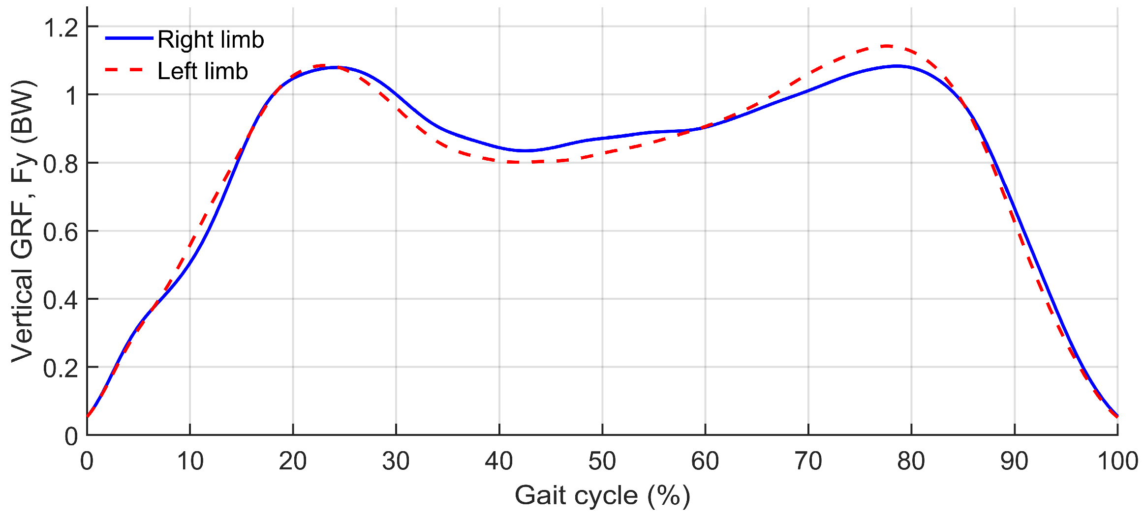
External loading conditions were first evaluated to confirm the physiological plausibility and mechanical consistency of the experimentally measured ground reaction forces before internal load analysis. Vertical ground reaction force (GRF) profiles for both limbs exhibited the characteristic double-peaked pattern associated with steady-state walking, with force magnitudes and timing consistent across the gait cycle (
Figure 2).
Peak vertical GRF values reached approximately 1.13 BW for the right limb and 1.14 BW for the left limb, which fall within the expected range for level walking.
The quality of foot-ground interaction was further assessed through center-of-pressure (COP) behavior during stance. No discontinuities or abrupt jumps in COP position were detected for either limb, and the COP trajectories progressed smoothly throughout the contact phase.
3.2. Inverse Dynamics Consistency Across Conditions
Inverse dynamics results were evaluated across all prosthesis parameter conditions to assess the internal mechanical consistency of the modeling pipeline.
Peak joint moments at the prosthetic socket–residual limb junction and ankle showed only minor changes in response to prosthesis mass variations (
Table 2). At the prosthetic socket level, peak moment magnitudes varied by ±2.1% relative to the baseline condition, while peak ankle moments remained unchanged across all mass levels. These small differences reflect the limited contribution of segment mass to inverse dynamics.
For inertia variations, inverse dynamics moments were effectively invariant (
Table 3). Peak moment differences remained below 1% for both the socket–residual limb junction and ankle, with identical peak timings across all inertia conditions. This confirms that modifications of inertial properties did not influence inverse dynamics outcomes when segment masses, kinematics, and external loads were held constant.
Similarly, mediolateral alignment perturbations produced no meaningful changes in inverse dynamics joint moments (
Table 4). Peak moment magnitudes and timing at both the socket–residual limb and ankle remained consistent with the baseline configuration, indicating that alignment-related effects do not manifest at the level of net joint moments.
The observed stability of inverse dynamics moments across mass, inertia, and alignment conditions confirms the numerical robustness and mechanical coherence of the analysis pipeline. Importantly, it demonstrates that any condition-dependent differences observed in subsequent joint reaction force analyses cannot be attributed to changes in inverse dynamics moments but instead reflect altered internal force transmission within the musculoskeletal–prosthesis system.
3.3. Residual Forces and Moments Across Conditions
Residual forces and moments acting at the model root segment were quantified for all simulation conditions to document dynamic consistency in the absence of residual reduction. Resultant residual force and moment magnitudes were computed from the translational and rotational pelvis residual actuator components, and RMS and peak values are summarized in
Table 5.
Across the inertia conditions, residual magnitudes remained effectively unchanged, indicating that the applied inertia perturbations did not alter the dynamic consistency of the inverse dynamics solution. Across the prosthesis mass conditions, only minimal variations were observed and no systematic increase in residual forces or moments was detected with increasing prosthesis mass. Alignment perturbations produced somewhat lower residual magnitudes relative to the baseline configuration, reflecting changes in the geometric relationship between ground reaction forces and the model root segment. Overall, residual trends did not indicate a systematic confounding effect of prosthesis mass, inertia, or alignment on the comparative interpretation of the joint reaction force sensitivity analysis.
3.4. Sensitivity of JRF to Prosthesis Mass
Peak joint reaction forces (JRF) at the prosthetic socket-level and prosthetic ankle exhibited a clear and systematic dependence on total prosthesis mass. Increasing prosthesis mass resulted in monotonic increases in loading, confirming a direct mechanical sensitivity of JRF to prosthesis mass. The magnitude of the socket-level reactions reflects rigid inter-segment constraint forces at a welded junction under prescribed kinematics and external loading. These values do not represent physiological contact stresses at the socket–residual limb interface, but the net mechanical load transmission. The emphasis of this analysis is therefore on relative changes across parameter conditions.
A summary of peak resultant JRF magnitudes and their relative changes across mass conditions for both joints is provided in
Table 6.
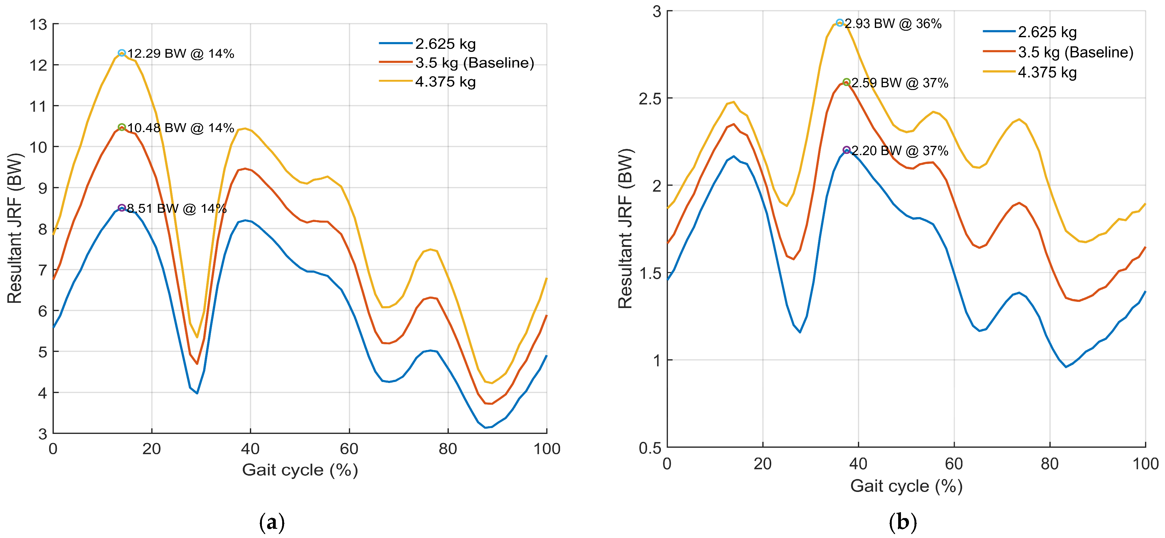
The timing of peak socket–residual limb loading remained constant at 13.9% of the gait cycle across all mass conditions. This indicates that prosthesis mass altered loading magnitude without affecting temporal structure. Peak ankle loading occurred at approximately 37–38% of the gait cycle, with only a minor temporal shift observed for the highest mass condition (36.1%), suggesting limited sensitivity of ankle loading timing to prosthesis mass.
To visualize the effect of prosthesis mass on constraint force transmission, resultant JRF profiles across the gait cycle for all mass conditions are shown in
Figure 3. No changes in waveform shape or phase shifts were observed, indicating that mass effects manifested primarily as magnitude scaling rather than temporal redistribution.
A three-point mass sweep indicated a substantially greater mass sensitivity at the socket–residual limb junction compared to the ankle. Based on the three tested mass conditions, the estimated sensitivity slope of peak resultant joint reaction force (JRF) was approximately 2.15 BW per kilogram, whereas the corresponding value at the ankle was approximately 0.42 BW per kilogram, indicating a stronger mass dependence of predicted constraint reaction forces at the socket level within the present model. These values should be interpreted as descriptive slope estimates from a three-point parameter sweep.
To clarify the mechanical origin of the observed increases in resultant JRF, reaction force components were examined at the same time instants corresponding to the maximum resultant magnitude for each joint and condition (
Table 7). In this context, JRF represents net constraint reactions describing internal load transmission across rigid prosthetic junctions.
Reaction force components are expressed in the global (ground) reference frame, Fy corresponds to the vertical axis. At both joints, mass-related increases in resultant JRF were primarily driven by concurrent increases in the ground-Y and ground-Z components, whereas the ground-X component remained comparatively small and showed limited sensitivity to prosthesis mass. At the socket–residual limb, peak loading occurred during early stance (approximately 14% of the gait cycle) and increased monotonically with mass, consistent with increased inertial and external load transmission across the socket-level junction. At the prosthetic ankle, a similar but attenuated pattern was observed, with smaller concurrent increases in the dominant components accounting for the rise in resultant JRF.
As an internal consistency check, JRF waveforms were inspected to confirm smooth, spike-free profiles, and resultant magnitudes were verified as the vector norm of components evaluated at the same time instants as peak resultant values.
Overall, increasing prosthesis mass substantially elevated prosthetic joint reaction forces, particularly at the socket-level junction, by amplifying the dominant reaction force components without altering the temporal structure of peak loading.
3.5. Sensitivity of JRF to Prosthesis Inertia
Joint reaction forces exhibited a measurable but notably smaller sensitivity to changes in prosthesis inertial properties compared to the effects observed for prosthesis mass. Variations in inertia resulted in moderate changes in the magnitude of peak joint reaction forces, with joint-specific differences in both magnitude and waveform behavior. A summary of peak resultant JRF magnitudes and their relative changes across different inertia conditions for both joints is provided in
Table 8.
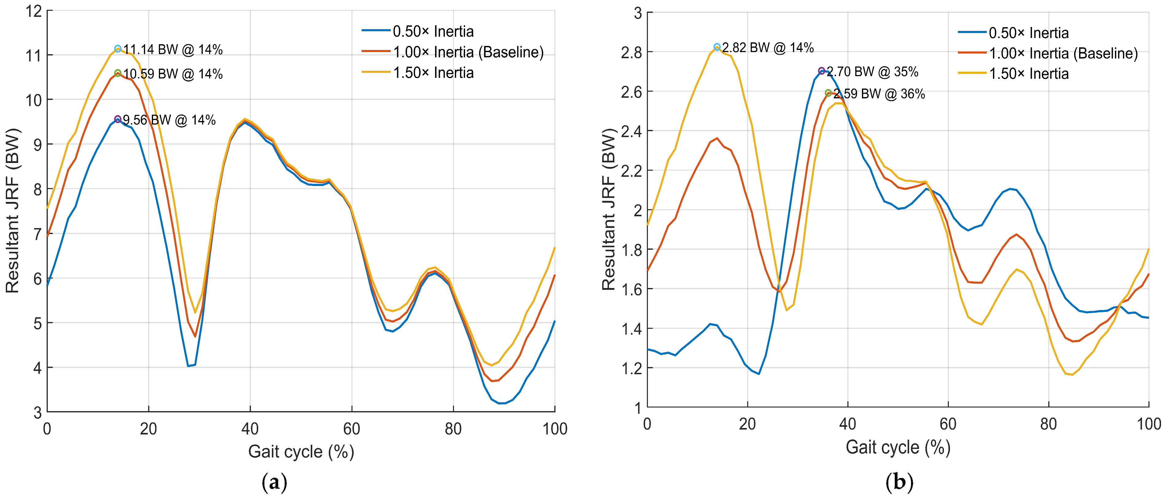
At the socket–residual limb junction, the timing of peak loading remained unchanged across all inertia conditions, consistently occurring at approximately 13.9% of the gait cycle, indicating that inertia modifications primarily affected peak load magnitude without altering temporal loading structure.
At the prosthetic ankle, inertia-related changes were associated with modest shifts in waveform shape and peak timing, indicating greater sensitivity of distal load transmission to changes in segment rotational dynamics. Importantly, the ankle response was not monotonic: both the low- and high-inertia conditions produced higher peak resultant JRF than the baseline condition. This pattern suggests that the ankle peak was influenced not only by the overall resistance to angular acceleration, but also by how inertia altered the temporal distribution and component composition of the reaction force during stance. In the low-inertia condition, reduced rotational resistance may have allowed more rapid segment acceleration and earlier force redistribution, increasing the instantaneous resultant peak despite lower loading during parts of early stance. In the high-inertia condition, greater resistance to angular acceleration likely increased distal inertial demand during dynamic phases, also elevating the peak resultant force. Accordingly, the baseline condition appears to represent a local minimum in peak ankle JRF within the limited three-condition inertia sweep, rather than evidence of a simple monotonic relationship.
The resultant joint reaction forces across inertia conditions are illustrated in
Figure 4. At the socket level, inertia variations produced largely parallel shifts in JRF magnitude while preserving waveform shape and phase, consistent with predominantly magnitude-based sensitivity. At the ankle joint, the low-inertia condition exhibited reduced loading during early stance, preceding peak occurrence, reflecting decreased resistance to segment acceleration.
These findings show that prosthesis inertia had a secondary but non-negligible effect on predicted joint reaction forces. Compared with prosthesis mass, inertia showed a smaller influence on peak loading magnitude at the socket level and introduced joint-specific temporal sensitivity at the ankle.
3.6. Sensitivity of JRF to Prosthesis Alignment
Mediolateral alignment was evaluated as a controlled geometric perturbation of the distal prosthesis relative to the socket–prosthesis junction (±10 mm). Under this one-factor-at-a-time design, between-condition differences in joint reaction forces reflect purely mechanical effects of alignment-related changes in effective load paths and moment arms, rather than subject-driven gait adaptations or variations in external loading.
Peak resultant joint reaction forces exhibited only minimal sensitivity to mediolateral alignment at both joints (
Table 9), with relative changes remaining below 1.5% across all conditions.
Although peak resultant magnitudes were largely insensitive to alignment, component-level analysis revealed systematic redistribution of joint reaction force components in the global reference frame, consistent with the intended mechanical effect of mediolateral translation. At the prosthetic socket junction, the dominant ground-Y and ground-Z components exhibited small but coherent shifts relative to baseline. Similarly, at the prosthetic ankle, alignment adjustments produced larger relative changes in shear-related components despite negligible changes in resultant magnitude.
In particular, the ground-X component remained small in absolute terms but showed the largest relative variation at the ankle (approximately ±4.7%), indicating that mediolateral alignment primarily influences the distribution of shear-related loads at distal prosthetic junctions but not overall peak load magnitude.
The observed alignment effects represent mechanical contributions under fixed gait inputs. In real-world prosthetic gait, alignment adjustments may be accompanied by user adaptation and altered external loading patterns [
9], which were not modeled in the present analysis.
4. Discussion
4.1. Mechanistic Hierarchy and Interpretation of Prosthesis Design Parameters
The present study identifies a mechanistically interpretable hierarchy of prosthesis design parameters influencing predicted constraint force transmission under fixed gait inputs. Before interpreting the hierarchy of effects, it is important to reiterate that the joint reaction forces analyzed here represent net rigid constraint reactions at prosthetic junctions under fixed kinematics and external loads, rather than in vivo muscle-mediated joint contact forces.
Direct measurements from instrumented prosthetic systems provide useful context for interpreting the magnitude of the modeled reactions. Instrumented transfemoral prosthesis studies have reported externally transferred interface-level loads during walking generally in the range of several hundred newtons to approximately 1–1.3 kN, depending on activity and measurement configuration [
12,
27]. In the present simulations, the baseline peak resultant reaction at the socket–residual limb junction reached 10.48 BW (≈7.4 kN for the 72 kg reference subject), while the prosthetic ankle peak reached 2.59 BW (≈1.8 kN). These magnitudes should not be interpreted as directly comparable to experimentally measured interface forces, as the modeled joint reaction forces represent net rigid-body constraint reactions required to satisfy the equations of motion under prescribed kinematics and external loads. In contrast, instrumented prosthesis studies measure externally transferred loads within the physical prosthetic system. While instrumented prosthesis studies provide valuable direct measurements of interface loads, they generally do not allow controlled isolation of individual prosthesis design parameters such as mass distribution, inertia, or alignment. The computational framework used in the present study enables such controlled parameter perturbations, allowing the relative mechanical sensitivity ranking of internal load transmission to different prosthesis design parameters to be systematically quantified.
Prosthesis mass produced the strongest and most consistent effect across all evaluated conditions, increasing peak resultant joint reaction forces (JRF) at both the socket level and the prosthetic ankle without shifting peak timing. This behavior is mechanically expected: added distal mass increases gravitational and inertial demands (m·g and m·a), and these additional demands are transmitted proximally, yielding the largest sensitivity at the socket level. This finding is consistent with prior evidence that added distal mass increases mechanical demands and energetic cost during walking [
28,
29].
Prosthesis inertia had a secondary, joint- and phase-dependent influence. Scaling inertia altered the resistance to angular acceleration, producing moderate changes in peak JRF magnitude, with minimal timing changes at the socket level but more noticeable timing and waveform effects at the ankle. This pattern is consistent with the greater sensitivity of distal segments to inertial resistance during dynamically demanding phases of gait [
22,
30].
Under the fixed gait inputs used in this model, mediolateral alignment (±10 mm) produced only minor changes in peak resultant JRF while redistributing force components in the global reference frame. Within the constraints of the present model, this reflects a predominantly geometric effect: alignment alters the load path and component resolution without substantially changing resultant force magnitude when motion and external loading remain unchanged. Clinically observed alignment effects on comfort and function often involve concurrent gait adaptations and neuromuscular responses, which were intentionally excluded here to isolate the mechanical contribution of alignment under fixed kinematic conditions [
31].
A key result is that prosthesis mass substantially affected JRF, while inverse dynamics joint moments remained largely unchanged. This is not contradictory but reflects a fundamental difference between outputs: with kinematics and GRF held constant, inverse dynamics moments are primarily determined by these prescribed inputs and thus show limited sensitivity to moderate changes in segment properties. In contrast, the modeled JRF includes the balance of gravitational and inertial forces within the multibody system and therefore responds directly to changes in segment mass and inertia under the prescribed gait inputs.
4.2. Clinical and Design Implications
Within the fixed-input conditions of the present model, the results suggest a mechanical prioritization of prosthesis parameters in terms of their influence on predicted constraint force transmission. Prosthesis mass showed the largest effect on predicted constraint reaction forces at the socket-level junction, indicating that distal mass was the dominant parameter within the tested conditions. Accordingly, reducing distal mass or redistributing necessary mass proximally may be an effective design hypothesis for lowering predicted constraint force transmission while preserving the timing structure of loading in this model.
Inertia appeared to play a secondary but still potentially relevant role: although its influence on peak magnitude is smaller than mass, it can modulate ankle loading behavior in a phase-dependent manner, suggesting that mass distribution relative to joint axes may influence predicted distal loading behavior during dynamically demanding gait phases.
Finally, mediolateral alignment produced only minor changes in peak resultant forces, while altering the distribution of individual force components. Under the present fixed-kinematic conditions, this suggests that alignment primarily modified modeled load pathways rather than peak resultant reaction magnitude. However, clinical alignment effects on comfort and gait quality are frequently mediated by changes in gait mechanics and neuromuscular coordination, which were intentionally excluded here.
4.3. Limitations
This study was designed as a mechanistic one-factor-at-a-time sensitivity analysis rather than a clinical validation study. Using fixed inverse kinematics and ground reaction forces excludes the neuromuscular adaptation typical of prosthesis users but enables the unambiguous attribution of mechanical effects. The gait inputs were obtained from a healthy reference subject, with transfemoral amputation introduced only at the model level. Therefore, the findings should not be interpreted as representative of transfemoral amputee gait mechanics. Instead, they should be understood as parameter sensitivities specific to the imposed healthy-reference kinematic regime, which may differ substantially from those that would emerge under amputee-specific compensatory gait patterns such as altered trunk motion, hip hiking, circumduction, pelvic drop, and asymmetric stance timing.
Joint reaction forces were used as model-based measures of constraint force transmission across rigid prosthetic junctions. In this framework, JRF represents net constraint reactions required to satisfy the equations of motion under prescribed inputs and should not be interpreted as physiological joint contact forces. Future studies incorporating multifactorial designs and adaptive gait responses are required to evaluate potential nonlinear interaction effects with clinically realistic conditions.