1. Introduction
The medical industry keeps evolving, moving towards an approach known as personalised medicine. Advances in manufacturing techniques, such as the introduction of the Additive Manufacturing (AM) technologies within healthcare settings, have contributed to this trend by realising medical devices that are able to meet the needs of individual patients and diagnostic cases via the fabrication of tailor-made devices [
1].
The phenomenon is beneficial in medical sectors such as those delivering orthotic therapies, which involve the use of external devices (i.e., splint, brace, orthosis) applied to patients with the purpose of partially or totally restricting the movement of joints or body segments [
2]. Research trials [
3], including those focusing on treatment for carpal tunnel syndrome, revealed that tailor-made orthoses shared promising clinical outcomes compared with pre-fabricated devices, although there is still no general consensus [
4]. Moreover, several studies [
5,
6] showed poor adherence in the use of passive pre-fabricated orthoses for the treatment of upper limb joints, including treatment for Duchenne Muscular Dystrophy affecting the hand, although the results reported positive effects on joint mobility. Associated with this matter, the reduction in patient compliance with therapeutic programs is attributable to poor comfort and freedom of movement associated with the use of orthoses [
7], but also the dimension and weight of the device [
8].
Within the framework of medical device customisation, the concept of Topological Optimisation (TO) represents a valuable instrument, able to redesign the basic structure of a prefabricated orthosis, enhancing the conventional idea of tailored-made medical device. Simultaneously, the tool realises lightweight elements without limiting their reliability and functionality [
9,
10,
11,
12].
Topological optimisation (TO) is a mathematical method widely used in civil and mechanical engineering in the design of physical systems and mechanical structures [
13]. The traditional TO approach based on the density method consists of the discretisation of defined areas into a grid of finite elements (e), described as isotropic solid microstructure) and characterised by the density distribution function of the material (ρ) within the design domain [
14]. The binary assignment of the material determines a discrete density distribution, where ρ(e) = 1 when the material is present and ρ(e) = 0 when the material is removed. To promote analysis stability, continuous density distribution is introduced: the intermediate level of the densities, ρmin < ρ(e) < 1, is assigned to each element, and a penalty factor (p) is adopted to limit the presence of intermediate density elements, fostering structural stiffness [
15,
16,
17]. The study of the optimal allocation of material in defined areas is dependent on the definition of objective functions and constraints. With advances in design engineering, TO caters to a wide range of requests, such as medical demands [
18,
19,
20,
21,
22,
23] related to the customisation of orthoses, based on the forces acting on the device during their utilisation [
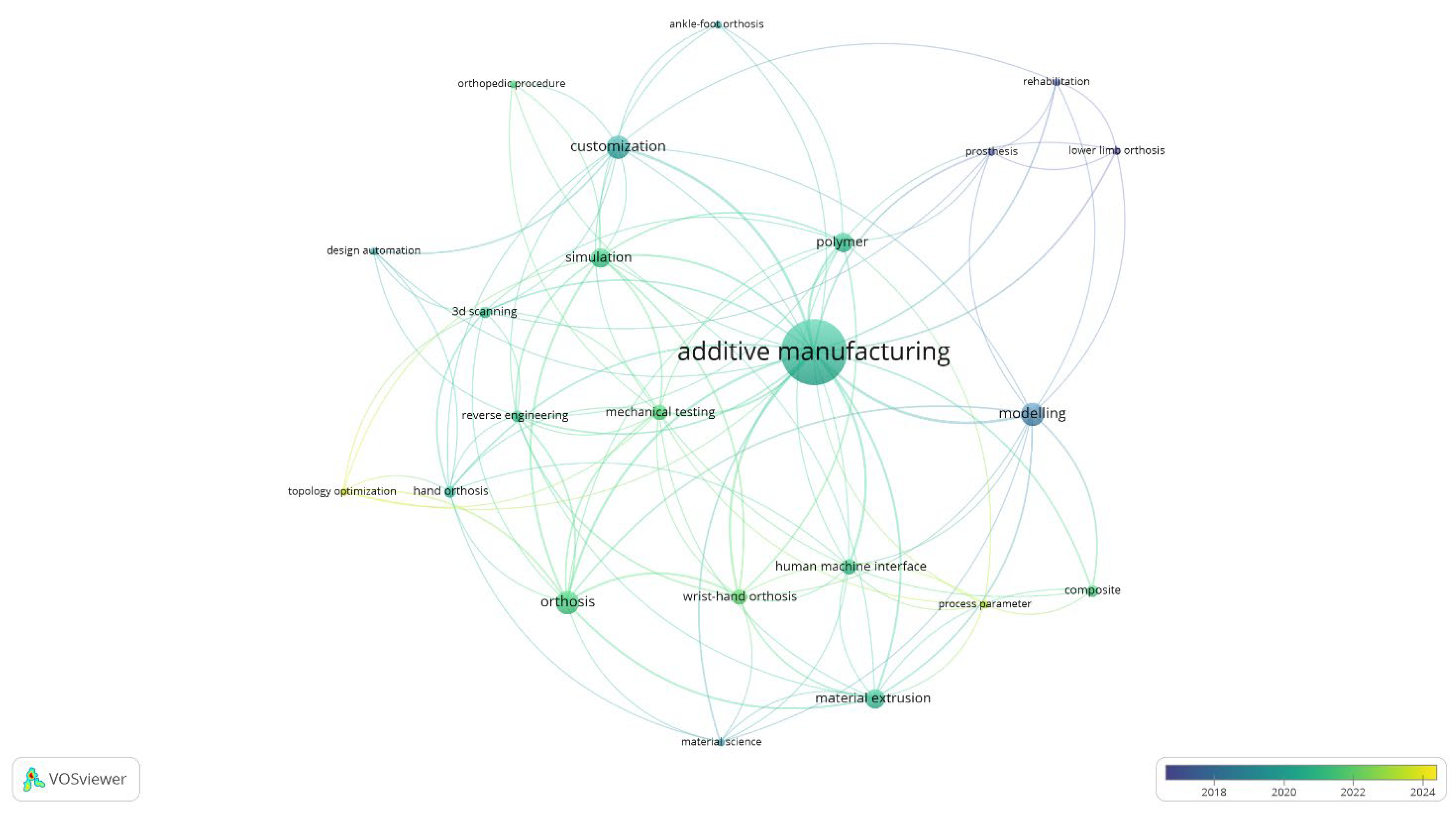
24]. In reference to the emergence of TO in recent research about customised AM-produced orthoses,
Figure 1 provides a comprehensive visualisation of the key topics and research directions. The map, generated through a VOSviewer keywords co-occurrence analysis, underscores the centrality of AM and identifies TO as an underexplored yet rapidly growing research area. The temporal distribution, primarily post 2018, reveals a marked increase in interest, suggesting that future research is likely to pivot towards this promising, yet relatively uncharted, avenue.
Besides the optimism, there is still a discrepancy between the implementation of TO methodology in the field of healthcare and orthopaedics. The hindered adoption is not a consequence of the lack of data documenting functional outcomes and the biomechanical performance of highly customised medical solutions, but rather the absence of multi-factorial studies examining the integration of the TO tool within the process chain. Although the benefits arising from the creation of customised devices are supported by scientific evidence, it remains unclear whether the integration of this tool is compliant with existing systems, platforms, and infrastructure.
Hence, the present research aims to investigate the use of the TO strategy as a methodology for customising medical devices with the aim of further lightening the structure while preserving the strength characteristics of the device. In the present research, TO emerges as the means of conducting broader research. In fact, this analysis evaluates multiple variables and factors influencing the production process; therefore, its usefulness extends beyond the simple purpose of material distribution optimisation. The tool was analysed with respect to the entire manufacturing process of orthopaedic devices, highlighting potential advantages and disadvantages associated with its implementation.
The study is based on an orthopaedic device belonging to the class of orthoses, also known under the name of splints and braces, which are elements worn in direct contact with the patient’s skin and responsible for the treatment of motor dysfunction of the wrist joint in rehabilitation programs.
The adopted methodology is presented in
Section 2, outlining the most significant activities to manufacture orthosis devices.
Section 2.3 delves into the TO topic; the study was conducted with Simulia Tosca, Academic License (Paris, France), an optimisation suite based on simulations executed using Abaqus FEA. The software was used with the intent of progressively lightening the orthosis, developing four different models with decreased percentages of residual volume fractions.
Section 3 discusses the results. Primarily, the feasibility of customising orthoses, either in terms of digital modelling or in terms of 3D printing, is examined. Furthermore, the strength and deformation behaviours are investigated in relation to the gradual lightening of the medical device and, insights on production time and production costs are presented. The document concludes with
Section 4, which summarises the purpose of TO for the advanced customisation of orthopaedic devices viewed in the face of the potential advantages and disadvantages that emerge.
2. Methodology
Currently, traditional manufacturing methods, often characterised by labour-intensive processes [
25], are predominant. However, the progress of advanced orthotic modelling and manufacturing is at an early stage of prototyping, likely because of the absence of regulations and guidelines for practitioners regarding the integration of advanced technologies in the clinical practice and the wide range of available techniques and materials that still necessitate further study and investigation.
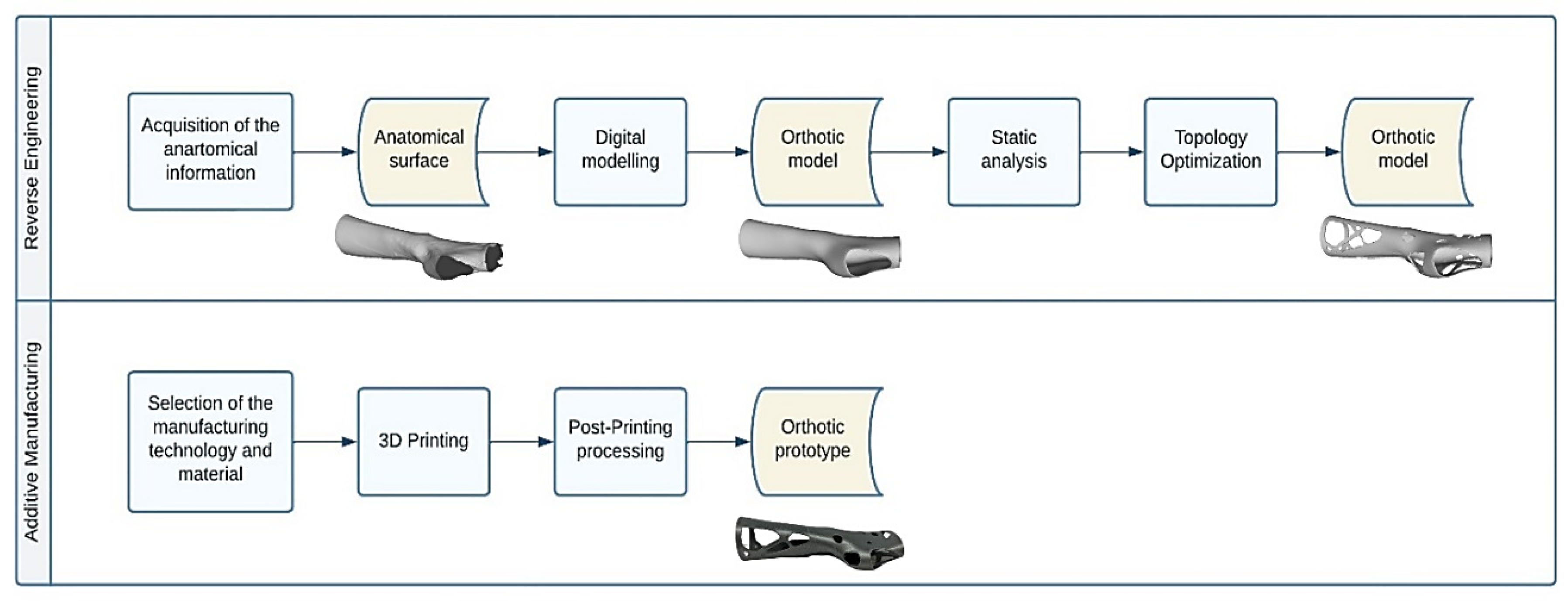
The modelling and manufacturing technique for orthotic devices dedicated to the upper limb joints, presented in the current research, relies on two main activities, namely Reverse Engineering (RE) and Additive Manufacturing (AM).
RE activity includes all the tasks necessary to obtain the final digital solid model of the medical device under investigation, starting from the patient’s anatomical information gathered, for example, with a 3D scanning system. At this stage, great relevance is paid to the activities involved in the modelling of the raw information with CAD software in order to transform the surface model into a truly wearable orthosis model. Once the desired digital model is obtained, the following task involves fabrication using AM techniques.
The computational instrument being investigated in this paper, namely Topology Optimisation (TO), places itself in the RE activity chain. In particular, TO lies outside of digital modelling, necessitating the execution of numerical simulations with the goal of defining the areas of the orthosis model subjected to reshaping.
The entire flow of operations involved in orthosis modelling and manufacturing is illustrated in
Figure 2 and outlined in the following paragraphs.
2.1. Digital Modelling
The need to individualise diagnostic treatment requires the production of an orthopaedic device to be tailored to the requirements and, specifically, to the anatomical characteristics of the individual diagnostic case. To comply with these specifications, a medical prototype was modelled from the geometry of the patient, which was captured through a laser scanner (Hexagon Absolute Arm 7-Axis equipped with RS6 Laser Scanner—Hexagon AB, Stockholm, Sweden). The superficial information was acquired in the form of a point cloud, converted into a format that is compatible with AM technology and modelled into a solid of the orthotic device.
As a consequence of the uniqueness of each clinical case, the transformation of the surface information into a 3D digital model of the orthopaedic device often involves performing a series of manual editing operations [
26,
27,
28]. Although general CAD software that caters to the demands of image processing is available, advanced programs [
29,
30,
31] able to accelerate and streamline the modelling activity in an effort to automate the procedure were found to be essential. The present research based the orthosis modelling activity on one of these assets [
31].
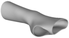
The modelling process developed an orthotic prototype resembling the design of the traditional circumferential wrist immobilisation pattern. The device consisted of two shells that join along the central axes of the structure and completely envelop the wrist joint, the thumb, and the fingers.
2.2. Static Analysis
At this stage, numerical analysis was conducted to evaluate the operating behaviour of the designed medical device, anticipating and correcting any design flaws or inefficiencies. Numerical simulations were conducted with Abaqus, a finite element method (FEM) suite involved in the study of the mechanical, thermal, and electromagnetic behaviour of structures and materials. Given the absence of specific mechanical tests designed to examine the standard behaviour of the considered medical device and taking into account that the device is not subjected to particular loads during its use, the present research simulated an accidental mechanical impact. Specifically, the present analysis was intended to represent the unintentional impact of the orthosis against a surface.
The experimental conditions were simplified, and two assumptions were made as follows:
The static analysis was performed without considering the presence of the forearm inside the orthotic device;
The static analysis was carried out on the device as a whole; connections among the interacting interfaces of the two shells were disregarded.
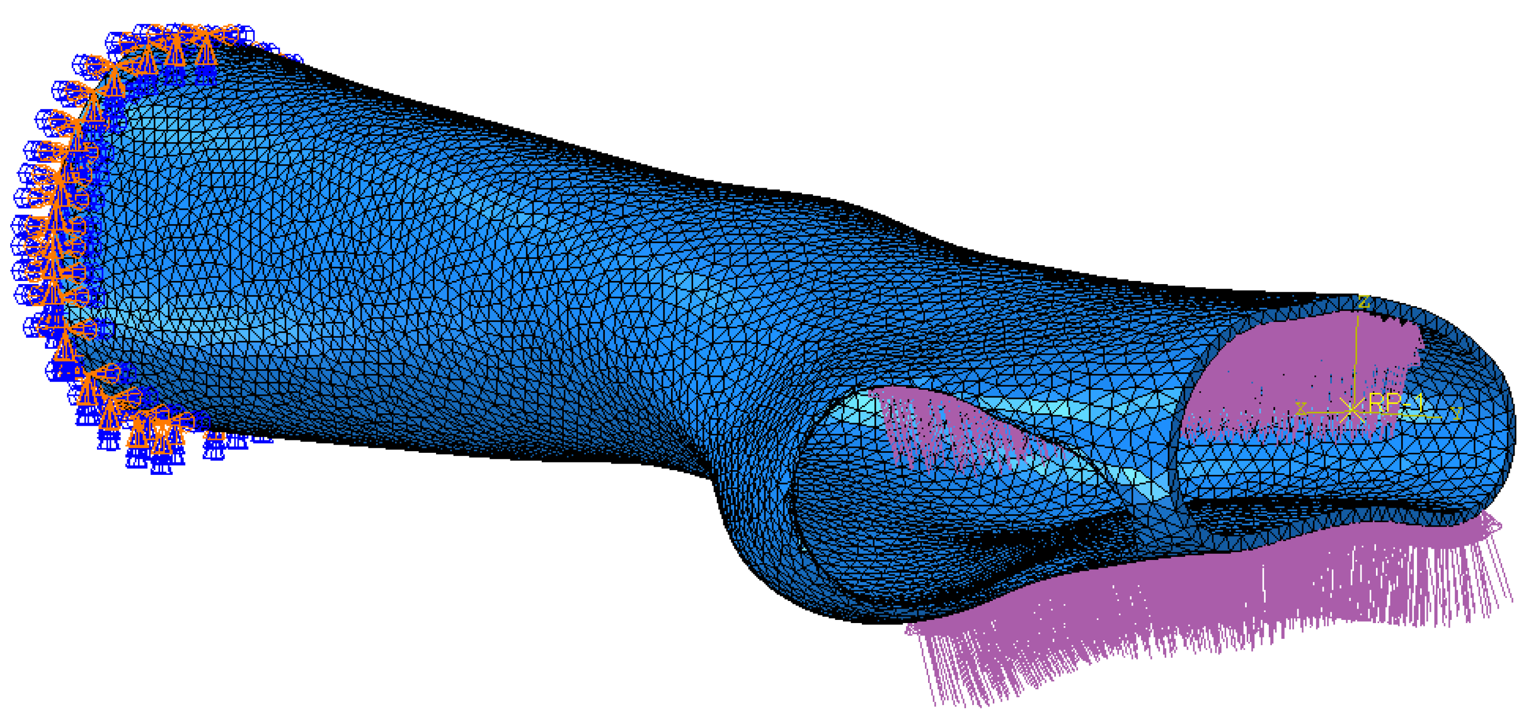
Based on these assumptions, the orthotic model was imported into the Abaqus simulation environment. The model was discretised into 40,680 quadratic tetrahedral elements with an approximate global size of 5 mm. Also, control over the minimum size of the mesh feature was defined as a fraction of 0.1, meaning that the minimum element size was set to 0.5 mm. A curvature control with a maximum deviation factor of 0.1 was applied to ensure that the mesh accurately captured the model’s surface geometry, minimising excessive approximations. In conclusion, the total number of nodes was 81,897. The defined parameters were validated by performing mesh size-dependency tests, ensuring that the accuracy and reliability of the results were not compromised by variations in the discretisation domain.
The orthosis was defined as a homogenous linear elastic structure with Young Modulus and Poisson’s ratio of the selected thermoplastic material. The boundary and load condition were established as depicted in
Figure 3. The distal end of the orthotic model (set of 450 nodes) was fixed with an encastre constraint. A load of 400 N was exerted as a pressure uniformly distributed over the palm of the hand (surface of 2259 faces). The simulation was run and the stress and displacement distributions, under the current experimental condition, were monitored.
2.3. Topology Optimisation
The numerical simulation about the orthosis mechanical behaviours was supplemented by a Topology Optimisation (TO) analysis, providing the development of innovative designs of orthopaedic devices. The study was performed with Simulia Tosca, an optimisation suite based on Abaqus FEM simulations. Indeed, from the analysis of the prescribed conditions of the FEM model, the software was able to determine the component areas subjected to elevated loads and suggest a geometry that optimised the stiffness of the structure.
The optimisation task used the general algorithm, partly described by Bendsøe et al. [
32]. Given the purpose of the study, namely the lightening of the orthotic structure, the whole model was selected as the design area. Two design responses were determined as follows: the energy stiffness measure identified the objective function, while the volume measure identified the optimisation constraint. Under the specified design responses, the optimisation task involved the minimisation of the energy stiffness measure respecting the requirement of structural volume. Four experimental conditions were planned; these comprised a volume reduction minor or equal to a percentage fraction of the initial volume, identified as 90%, 80%, 70% and 60%, respectively. A geometric restriction was added to further constrain the TO process, specifically that the edges of the orthotic model were preserved as frozen areas (4822 elements). The maximum number of iterations to be performed was set to 50, which proved to be a sufficient number of iterations to enable the algorithm to reach a stable solution and find convergence.
2.4. 3D Printing
The customised orthotic designs, obtained from the topological modelling and optimisation activities, were 3D-printed using Material Extrusion (MEX) technology, Ultimaker S5—Ultimaker B.V., Utrecht, The Netherlands. Thermoplastic polymeric filaments, with a diameter of 2.85 ± 0.10 mm, were employed for the manufacturing of the orthotic prototypes. PLA was the selected material; it is well suited for the current medical use, presenting faster printing times than other materials too. This makes it a practical choice both timewise and economically. The properties of PLA are reported in
Table 1.
The models were sliced, and their printing settings (
Table 2) were defined in Ultimaker Cura (v5.3.0). The prototypes were 3D-printed with a 100% infill density and a 0.8 mm head nozzle, capable of realising a layer height of 0.6 mm. Some features of the prototypes required the use of support material (PLA or Ultimaker Breakaway, a mixture of PLA and TPU), extruded from a second printhead with a 0.8 mm head nozzle and 0.6 mm layer height.
3. Results and Discussion
3.1. Design of the Optimised Models
The current section presents the results of topological optimisation from the point of view of the process of medical device design; the geometric properties of the structures were also observed.
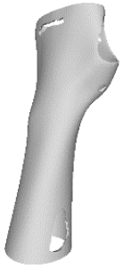
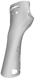
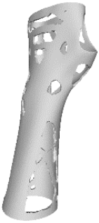
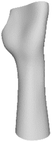
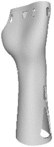
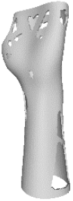
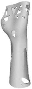
Digital modelling led to the construction of an orthotic prototype (see
full model, pictures of
Table 3) for the treatment of wrist pathologies. The element has a dimension of 94 × 82 × 228 mm
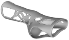
3. The subsequent activities of static analysis and TO resulted in the creation of five solid models, which differed according to the fraction of residual volume (RVF) (see
Model 1,
Model 2,
Model 3 and
Model 4, line 1–2 of
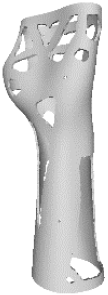
Table 3). Some regions of the material were removed, as, in those regions, the material does not contribute significantly to the strength and overall performance of the whole system; this is presented in
Table 3. Based on an initial observation, the regions of the structure that were less susceptible to material removal were the upper portion of the forearm and the wrist.
The structures of Model 1, Model 2, Model 3, and Model 4 attained convergence and stability at the 24th, 30th, 33rd, and 41st iteration cycles, respectively, thus requiring fewer iterations than the predefined maximum value of 50 design cycles. The final structures were taken from the last iteration step, guaranteeing that the selected configurations corresponded to the stable, converged states achieved at the end of the optimisation process. In every instance, the volume constraint was satisfied, and, for the last iteration step, was always slightly below the target volume constraint value (0.0004% deviation). It is worth noting that, when exporting the topological optimised model from Abaqus, the software may simplify and/or approximate the geometry due to the realisability of the part, leading to slight variations in the resulting models. This is the motivation behind the difference between the target RVF or RV (i.e., the volume values set up as constraints in Abaqus) and the measured RVF or RV (i.e., the volume values measured in the exported files using other 3D file processing software).
The logic of material preservation is determined by the TO algorithm utilised. The progressive reduction in material occurs through the creation of new holes and/or enlargement of the holes created during the previous TO iterations. The holes created in the structure are characterised by an asymmetrical and irregular shape as a result of the material re-distribution aimed at reducing the volume of the structure without constraining it to a predetermined or preestablished shape. Therefore, given that TO provided only an indication of how the structure should be revised, geometrical modifications to adjust the holes or adapt them to specific feasibility requirements are required in the post-processing activities. This necessity opens up opportunities for exploring innovative approaches to manage the voided areas identified by TO in modelling phases too, for example, by employing lattice geometries to fill the voids and mitigate practical design inefficiencies.
3.2. Mechanical Performances of the Optimised Models
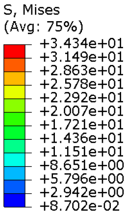
The mechanical properties of the models of the medical devices were investigated by conducting analyses on Von Mises stresses and deformations (measured in terms of displacements from the initial unperturbed model). The results were derived from the static analysis described in the methodology section.
Table 4 provides information on the stress state to which each model of orthosis was subjected under the specified load. The equivalent stress values of the structures of the
full model and
Model 1,
Model 2,
Model 3 and
Model 4 consistently remained below the UTS of the manufacturing material (56.0 MPa). Moreover, on average, the stress did not exceed 30 MPa, with the exclusion of a particular region within the opening intended for the thumb finger, where the maximum stress value was recorded. This demonstrated that the volume reduction strategy, even in the lightest configurations, did not adversely affect the strength of the material. In fact, the models presented satisfactory safety factor values, compatible to the safety factors identified for medical devices of the same kind [
24,
33,
34].
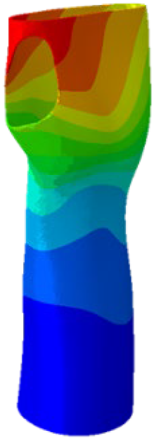
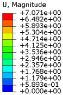
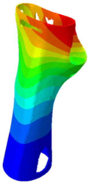
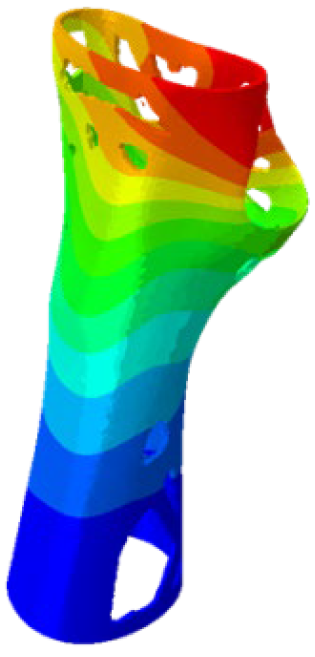
Table 5 presents an analysis of the magnitude of the displacement. The maximum displacement values were recorded on the upper edge of the medical device, close to the hand area; these range from 7 mm (
full model) to almost 12 mm (most lightweight model,
Model 4). It is worth noting that the critical displacement values are the ones affecting the area of the wrist joint: the displacement values recorded in this area were around 3 mm (
full model) and around 6 mm (
Model 4). Considering the functionality that the medical device must achieve, the deformation values obtained were not completely negligible.
The main results related to the mechanical characteristics, intended as the evaluation of Von Mises stress and displacement, according to the variation in the volumetric dimension of the medical device implemented through the TO, are summarised in
Table 6.
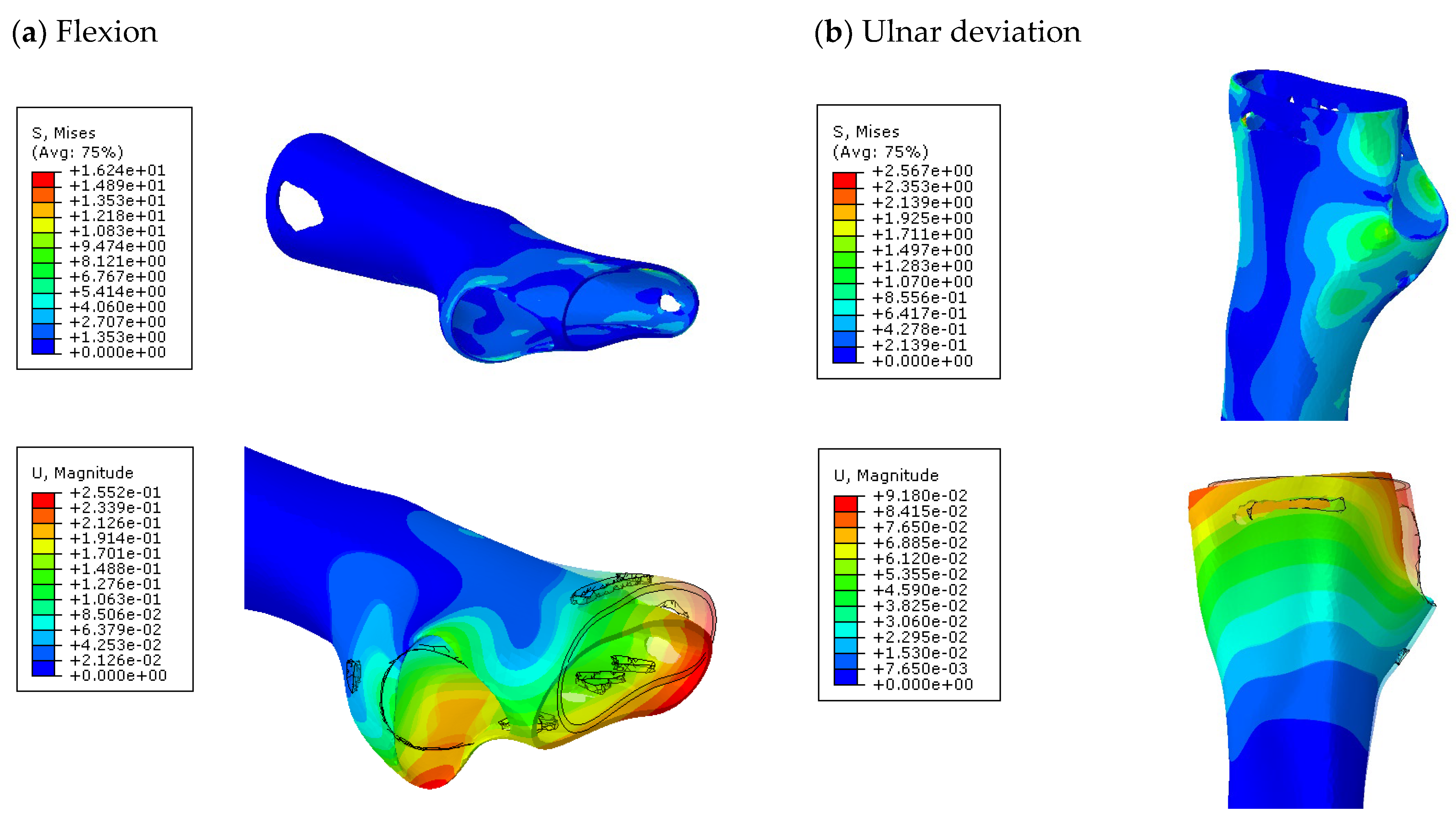
Further analyses of the mechanical behaviour of the four TO orthosis models (
Model 1 to
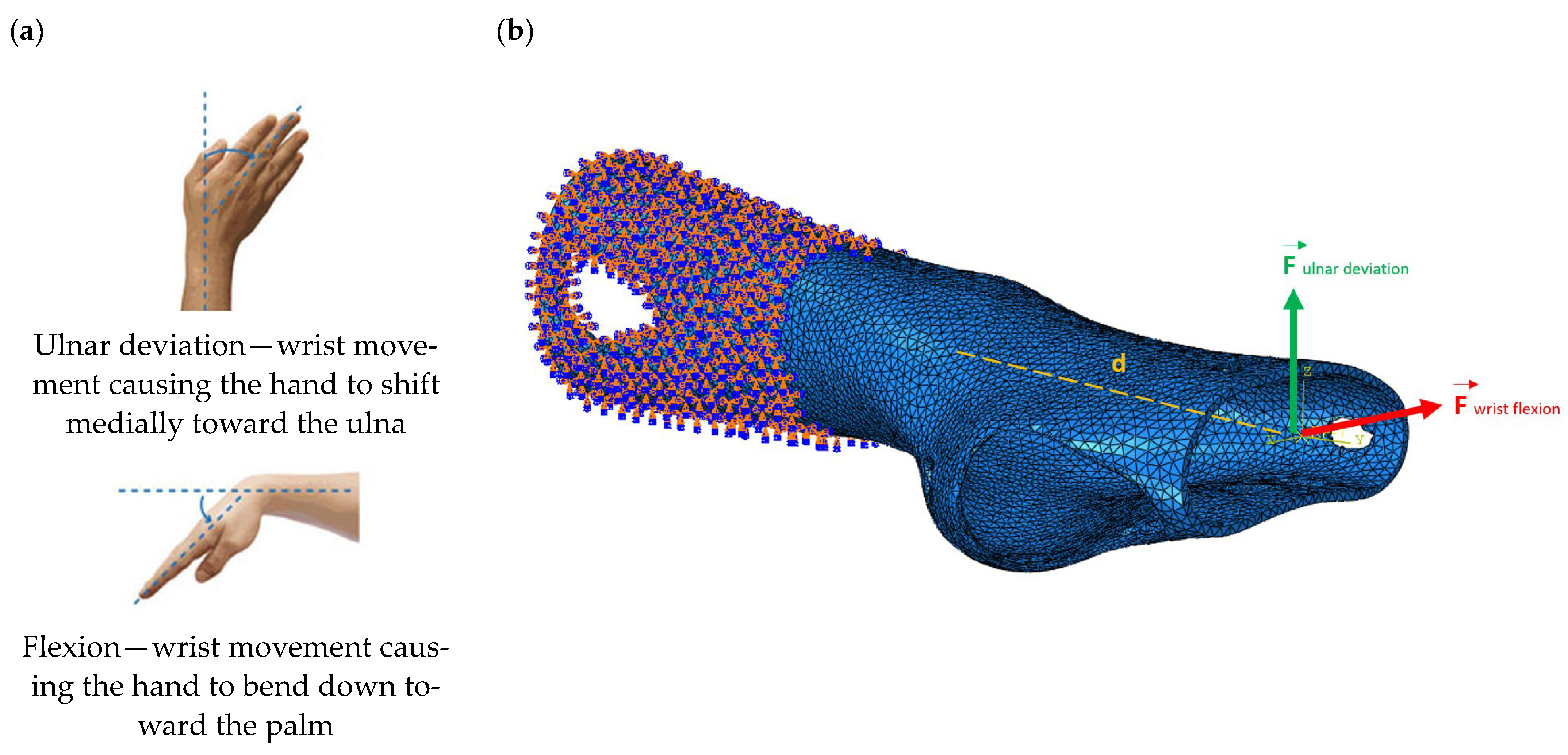
4) were conducted to simulate the response of the structures to wrist movements. Specifically, the simulations focused on wrist flexion and ulnar deviation (see
Figure 4). Although extension and radial deviation are also significant, these movements typically involve a restricted range of motion and generate forces characterised by lower intensity compared to flexion and ulnar deviation. Furthermore, they are less relevant in daily wrist activities such as gripping or lifting activity.
The simulations were performed accordingly to the procedure already defined in the Methodology section. In these analyses, the ulnar deviation and flexion movements were represented as moment loads, which were applied to the distal perpendicular surface of the orthosis (in proximity to the fingers), while the proximal region of the orthosis was constrained with an encastre boundary condition. The applied forces in both scenarios were chosen to represent conditions compatible with joints in the late stages of rehabilitation, during which the patient requires minimal support from the device and is capable of exerting moderate forces. Specifically, for ulnar deviation, force F = 30 N and lever arm d = 75 mm were used, while for wrist flexion, F = 50 N and d = 75 mm were applied.
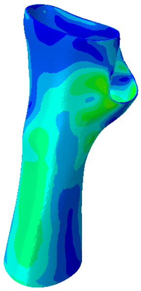
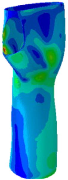
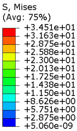
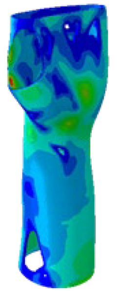
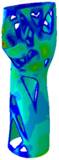
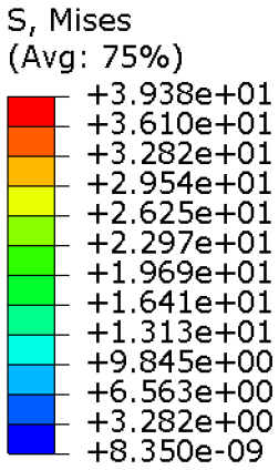
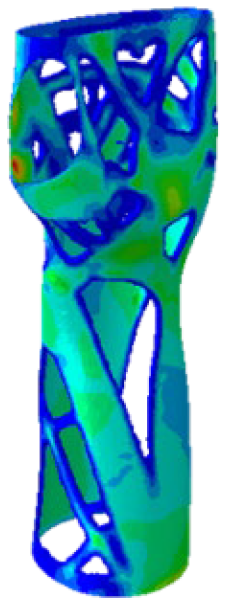
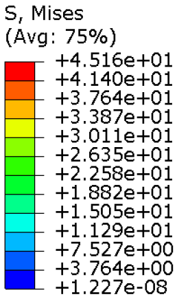
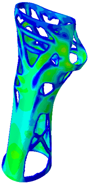
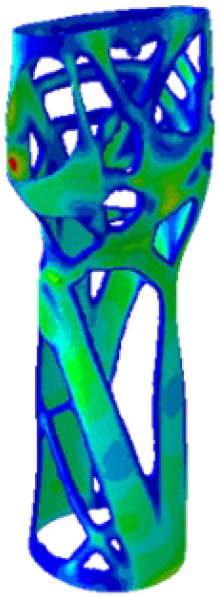
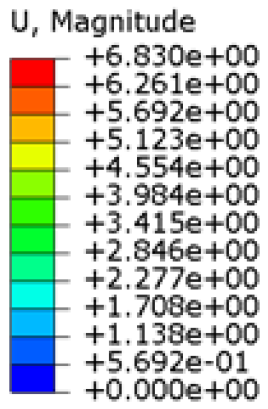
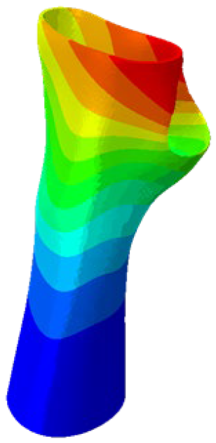
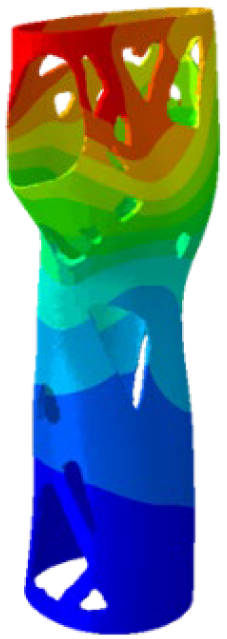
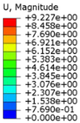
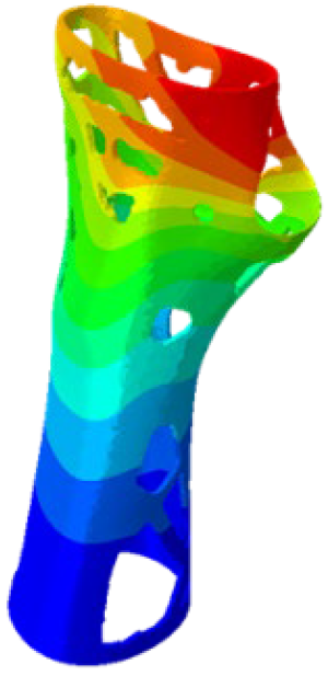
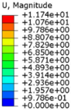
The mechanical response of the orthosis, in terms of Von Mises stress and displacement, to the applied moment load is illustrated in
Figure 5, representing
Model 1. As expected, in the case of ulnar deviation, the orthosis structure experiences increased lateral stresses due to the concentration of forces along the sides of the device. However, for wrist flexion, the loads are primarily distributed across the dorsal and palmar surfaces of the device. The behaviour of
Models 2,
3, and
4 is consistent with that of
Model 1, differing only in exhibiting higher displacements and stress concentrations near the apex of the voids generated through the TO process.
The results, measured in terms of Von Mises stress and displacement, are summarised in
Table 7. The stresses are consistently below the material UTS. The deformations, quantified as global measures of displacements, are insignificant. Also, it is worth noting that the displacements along the specific directional components of the wrist movement (i.e., lateral direction for ulnar deviation and vertical direction for flexion) are lower than the global displacement values obtained by considering all three axial components combined (U, magnitude).
The findings suggest that the orthosis designs maintain their structural integrity and functionality even during the patient’s rehabilitation phase.
3.3. Rapid Prototyping of the Optimised Models
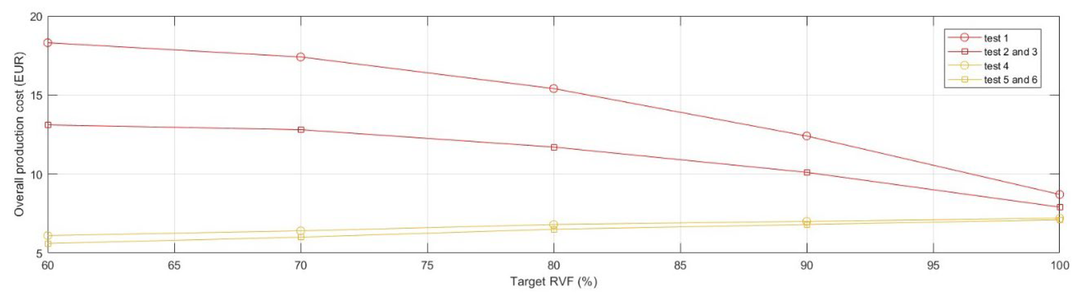
In the present section, an analysis focusing on manufacturing time and cost was conducted with the objective of assessing the impact of TO activities on rapid prototyping. Specifically, the benefits derived from the material redistribution were observed from the production process perspective.
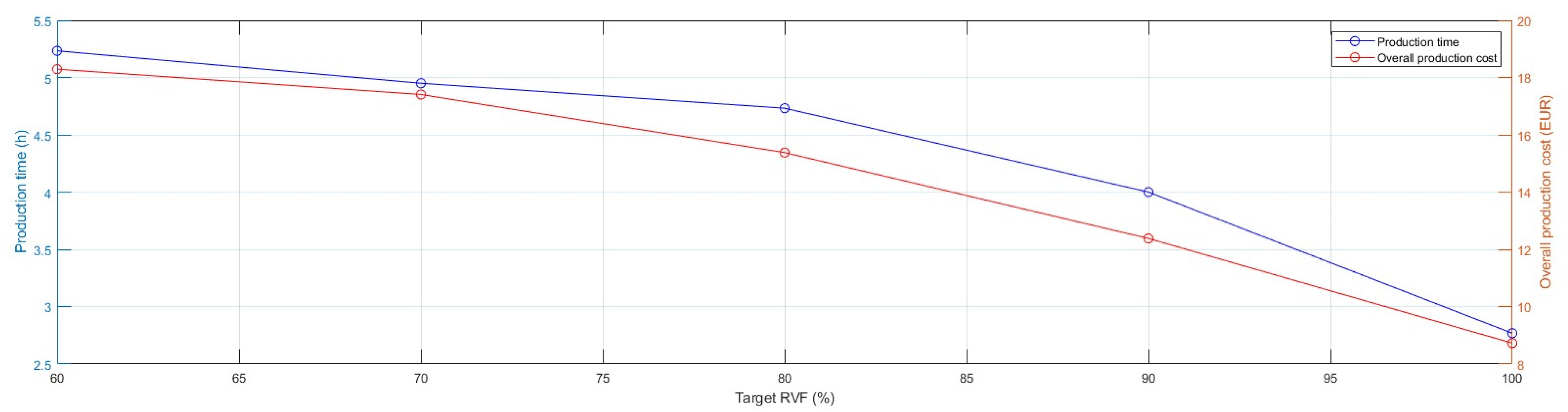
Originally, the prototypes were produced using the default optimal printing parameters (
test 1); the model was 3D-printed in PLA (~0.57 EUR/m) with dual extrusion to realise the default support structures in Ultimaker Breakaway (~0.92 EUR/m). The models were manufactured successfully without experiencing difficulties. Observing the production cost, expressed as raw material cost, and production time required to realise the products, the critical issues of the volume reduction strategy employed through TO visibly emerged (
Figure 6).
The incremental growth in the complexity of geometries in TO models, characterised by large overhangs and irregular holes, required a significant increase in the use of support material to prevent the collapse of the articulated features. Thus, the production time extended and, in the present instance, almost doubled by moving from 2.8 h for realising the
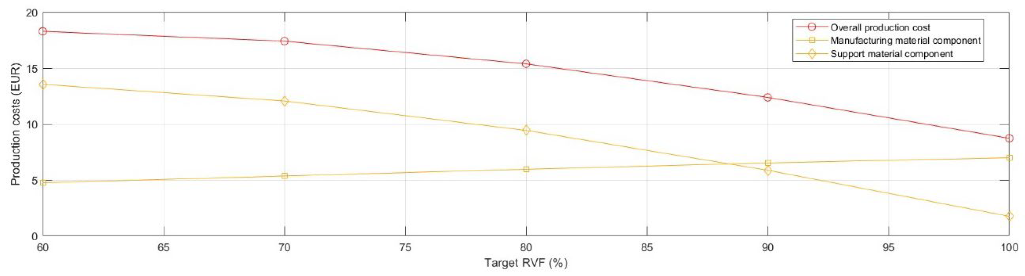
full model to 5.2 h for the lightest one. As shown in
Figure 7, the advantageous cost effect of reducing the use of manufacturing material due to TO was nullified. Specifically, the overall production cost of
Model 4 doubled and its support material cost component increased seven-fold compared with the
full model.
In order to mitigate the observed growth in production cost and time, a deeper analysis of support structures was required and, particularly the optimisation of the aspects of design and printing parameters of the support structures, together with the support material selection.
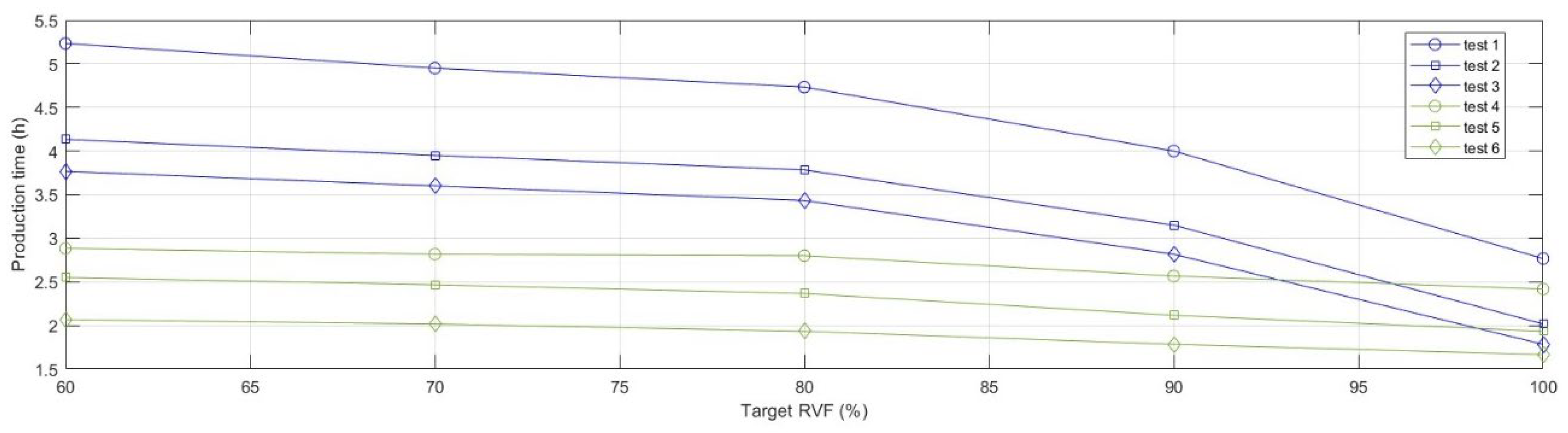
Following a Design of Experiment (DOE) plan, a series of tests were planned to observe variations in production time and cost over the different values of the Target RVF. The first aspect considered the support material, which was distinguished into the recommended standard support material (Ultimaker Breakway, a mixture of TPU and PLA) and a support material equal to the structuring material (PLA). Using Ultimaker Breakaway allows for better surface accuracy by swiftly and cleanly detaching the support parts from the 3D-printed element. Using the same material filament (PLA) for both the support part and the structuring part may require post-production processing to improve surface quality, yet it allowed to examine the transition from dual-extrusion mode (two printheads) to single (one printhead). Further, the design of the support structure was analysed, finding that the tree support structure (individually developed with Meshmixer software, with an overhang angle of 45°) substituted the default structure provided by the slicing software Cura (linear support with an overhang angle of 45°).
Hence, the experimental design plan (
Table 8) was structured as follows:
Ultimaker Cura Default support structure (test 1, test 2 and test 3) and tree support structure (test 4, test 5 and test 6);
Ultimaker Breakaway support material (test 1 and test 4) and PLA support material (test 2, test 3, test 5 and test 6);
For the tests employing the same material (PLA) for both the structuring part and the support part, dual extrusion (test 2 and test 5) and single extrusion (test 3 and test 6) are used. Note, that processes involving different materials (test 1 and test 4), by principle, use the dual-extrusion mechanism.
Table 8.
Experimental design plan.
Table 8.
Experimental design plan.
| | Support Structure | Support Material | No. Extruders |
|---|
| Test 1 | Default | Breakaway | Dual |
| Test 2 | Default | PLA | Dual |
| Test 3 | Default | PLA | Single |
| Test 4 | Tree | Breakaway | Dual |
| Test 5 | Tree | PLA | Dual |
| Test 6 | Tree | PLA | Single |
Prototypes, belonging to the different tests, were 3D-printed to ensure feasibility in the production process. The results of the performed tests were collected in
Figure 8 and
Figure 9, that, respectively, depict the evolution of the curves of manufacturing time and cost as a function of medical device lightening. It is possible to highlight how the use of tree-structured support and the use of a unique material, for both the support part and the structuring part, extruded from a single nozzle significantly influence the 3D printing time. Furthermore, following the parameter optimisation, it is also possible to observe an overall flattening of the curves of production times as the volumetric reduction of the device progressed. Comparably, a reduction in the overall production cost was observed. The parameter optimisation affected only the cost component related to the support structure. The optimal result, measured in terms of either production time or production cost, was
test 6.
Table 9 and
Table 10 summarise the outcomes of the default printing strategy (
test 1), which returned the worst results, and the optimal printing strategy, which can be identified in
test 6. Besides the absolute values, the percentage values are reported with respect to the default strategy for manufacturing the
full model.
4. Conclusions
In the present research, the use of Topology Optimisation (TO) as an approach for customising orthopaedic medical devices, specifically orthoses and splints for immobilisation of the wrist joint, was investigated. TO was performed through the Simulia Tosca optimisation suite of the Abaqus software with the objective of lightening a predetermined model of the medical device, by ensuring an extremely customised design that was satisfactory to the patient’s individual preferences and conformed to their wearing schedule. The objective of the research was to identify the influence of TO strategy through a multi-factorial evaluation that not only considered the product perspective, but included factors belonging to the entire process chain.
The results of FEA analyses showed acceptable stresses for all models; moreover, the points of the structure under maximum stress presented a safety factor that was always greater than 1.2. Deformations in terms of displacement were not excessive, but could not be entirely neglected. Although the benefits resulting from TO activity were evident, from the production process perspective the advantages were not so clear. The manufacturing time and cost of the lightened models experienced a rise due to the growing need for more support materials to handle the new and articulated geometries; thus, an optimisation of the process parameters, especially the parameters related to the support material, was undertaken. After optimising the 3D-printing strategy, the material cost of the lightest model (Model 4) was lowered by 22% compared to the full model, strongly demonstrating the economic advantage of TO. In terms of fabrication time, the increase was partially contained; the difference in production time between the full model and Model 4 was +24%, while in the non-optimised 3D-printing strategy it was +86%.
In summary, TO proved to be a valuable approach for the advanced customisation of orthopaedic devices. Although TO is a functional tool for suggesting an initial design idea rather than providing a complete final model, all the lightened geometries were produced without experiencing issues. However, it should be noted that arranging modelling activity to adjust the geometry of the rough topology and finishing treatments could be valuable both from the perspective of the manufacturing process and from the perspective of patient’s wearing schedule and compliance.


