Article

Evaluating Angled Abutments: Three-Dimensional Finite Element Stress Analysis of Anterior Maxillary Implants

1
Department of Aeronautical and Automobile Engineering, Manipal Institute of Technology, Manipal Academy of Higher Education, Manipal 576104, Karnataka, India
2
Department of Conservative Dentistry and Endodontics, Manipal College of Dental Sciences, Manipal, Manipal Academy of Higher Education, Manipal 576104, Karnataka, India
3
Department of Oral and Maxillofacial Pathology and Oral Microbiology, Manipal College of Dental Sciences, Manipal, Manipal Academy of Higher Education, Manipal 576104, Karnataka, India
4
Department of Mechanical Engineering, Hirasugar Institute of Technology, Nidasoshi, Belagavi 591236, Karnataka, India
*
Author to whom correspondence should be addressed.
Prosthesis 2024, 6(2), 315-328; https://doi.org/10.3390/prosthesis6020024
Submission received: 15 January 2024 / Revised: 2 March 2024 / Accepted: 2 March 2024 / Published: 25 March 2024
(This article belongs to the Collection Oral Implantology: Current Aspects and Future Perspectives)

Abstract

:
Restorative dentistry is the repairing of damaged teeth and restoring oral health and function. Dental implants are typically placed within the cortical bone of the jaw to provide stability and support for prosthetic restorations. The successful restoration of complex anatomical features of the maxillary anterior is difficult for prosthodontists. Using a 3D slicer, CT scan images were used to create a detailed three-dimensional model of the maxilla bone. This study utilizes ANSYS Workbench, a finite element software program, to analyze the abutment angles, ranging from 0° to 25°, and the impact stress distribution within peri-implant bone. The outcomes of our studies align with and substantiate certain evidence in the literature documenting bone resorption, specifically at the level of the implant neck and near the cortical bone. The study aims to provide a comprehensive understanding of angled abutment stress patterns in the bone surrounding dental implants, offering valuable insights for clinical applications in critical areas of the mouth.

1. Introduction

Restorative dentistry is the repairing of damaged teeth and restoring oral health and function. Whether it is fixing cavities, replacing missing teeth with implants, bridges, or dentures, or repairing cracked or broken teeth, the primary objective is to enhance the overall health of the mouth and improve the chewing and speaking ability [1,2]. For patients with missing teeth, achieving a natural and aesthetic appearance is critical. For successful restorations, replicating the shape and size of the teeth, gum contours are essential [3]. Due to the complex anatomical features of the maxillary anterior teeth, restorations are difficult for prosthodontists [4]. To address these challenges, prosthodontists employ advanced imaging technologies such as CT scans and digital impressions to derive a better understanding of a patient’s anatomy. Dental implants and dentures are used as the materials and techniques to address functional aspects, but also ensure the desired aesthetic outcome [5].
The temporomandibular joint (TMJ) produces varying degrees of force during chewing hard or soft foods, speaking, and even grinding teeth. These forces can impact not only the joint itself, but also the teeth and their supporting structures [6]. When a tooth is lost, the underlying bone in the jaw starts to resorb or shrink over time due to lack of stimulation, leading to changes in the bone structure. This can complicate the placement of dental implants or affect the fit of prosthetic devices. Additionally, surrounding teeth tend to shift or move into the space left by the missing tooth. This can cause misalignment issues, affecting both aesthetics and bite function. To effectively rehabilitate a missing tooth, dentists or prosthodontists need to consider the specific circumstances of each patient. This includes assessing the condition of the surrounding teeth, the health of the gums and jawbone, and the patient’s preferences [7]. Dental implants are often considered the gold standard for tooth replacement because they mimic the natural tooth root and provide stability for various prosthetic options [8]. However, the success of implants depends on adequate bone volume and quality. Bridges and partial dentures are alternative options, but they may have limitations in terms of stability, the impact on adjacent teeth, and long-term maintenance [9]. Dental implants are typically placed within the cortical (dense outer) bone of the jaw to provide stability and support for prosthetic restorations. In cases of bone deficiency, additional procedures such as bone grafting may be necessary to augment the bone before implant placement. This can increase the complexity and time involved in the overall treatment process.
If the natural orientation of the bone is not ideal for implant placement, implants may need to be inserted at angles to achieve proper support for prosthetic restorations. This process is technically challenging, and the use of angled abutments or specialized implant systems may be required. Precise planning through imaging techniques such as CT scans is crucial to avoid complications during implant placement [10,11]. Angled abutments are indeed valuable tools in managing the placement of an implant in the premaxilla zone of the mouth due to bone morphology and adjacent teeth angulations. In such cases, the positioning of implants might deviate from the ideal angle perpendicular to the occlusal plane. Typically, angled abutments range from 10° to 60°. These abutments enable adjustment of the orientations of the tilted position of the implants [12,13].
Customized angled abutments offer a highly tailored solution in situations where standard angled abutments might not perfectly fit the patient’s unique anatomy [14]. The fabrication of customized angled abutments often involves advanced CAD/CAM technology or traditional laboratory techniques, such as casting or milling based on digital designs.
The finite element method is a valuable tool in medical implant and human organ research, providing a detailed and quantitative understanding of the mechanical behavior of implants in the oral environment [15,16,17,18]. This study utilized finite element analysis to investigate the varying abutment angles, ranging from 0° to 25°, impact stress distribution within the peri-implant bone. Specifically focusing on the anterior maxilla, the goal was to systematically measure and compare stress levels. The study aimed to provide a comprehensive understanding of angled abutment stress patterns in the bone surrounding dental implants, offering valuable insights for clinical applications in critical areas of the mouth.

2. Materials and Methods
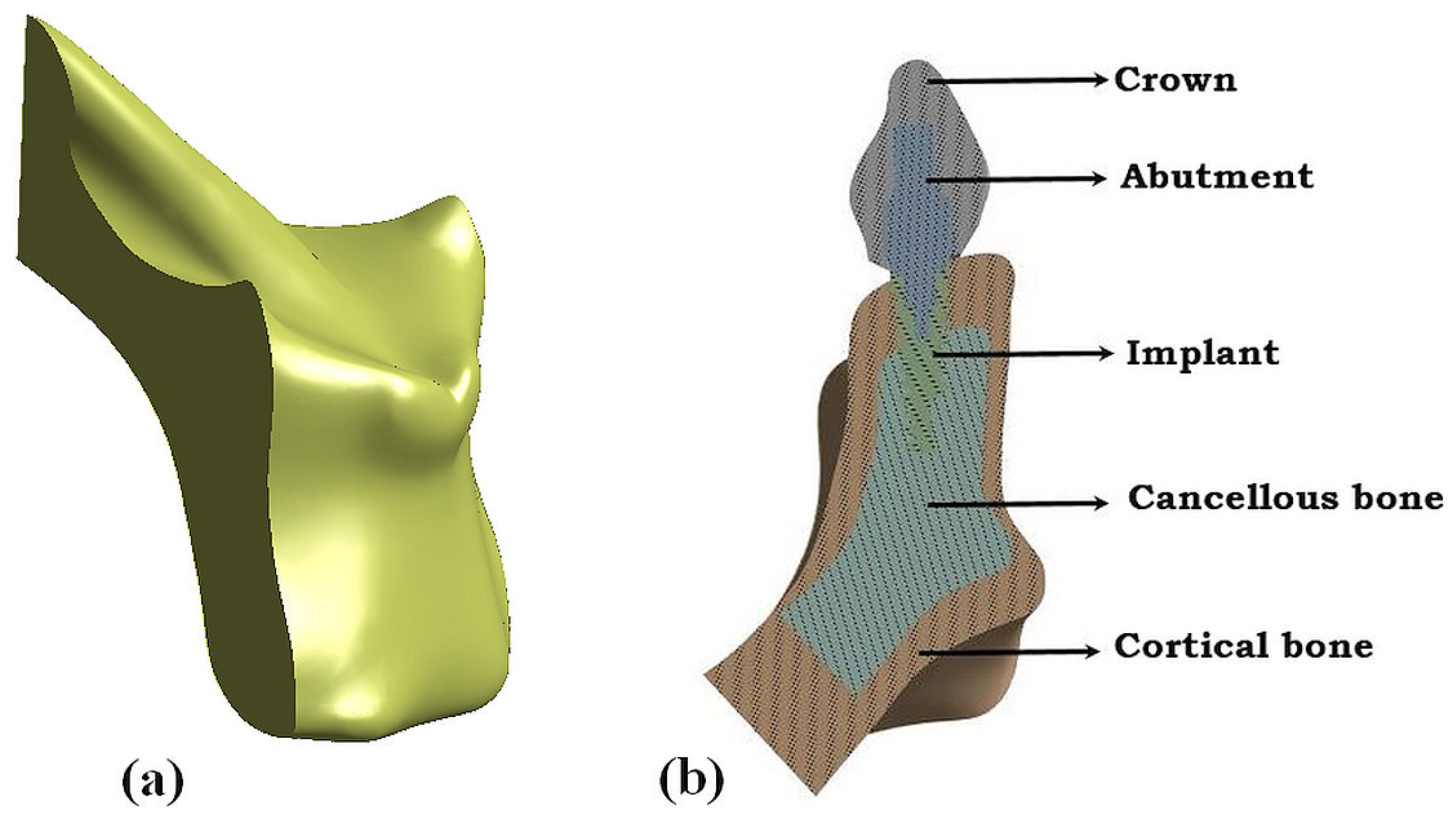
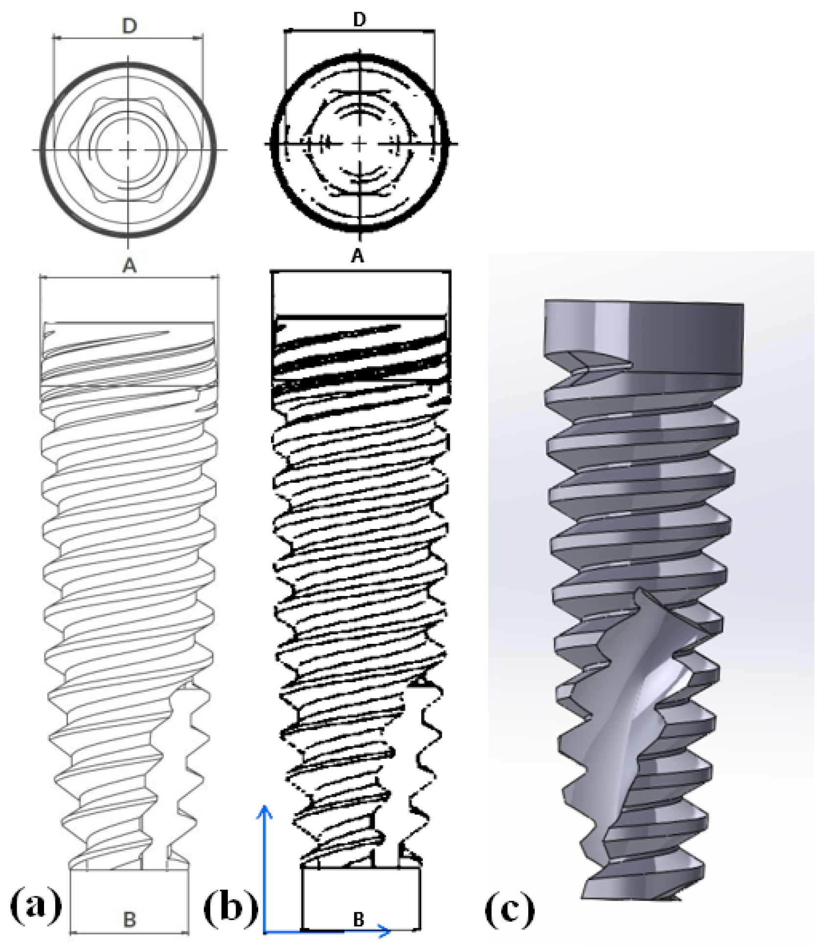
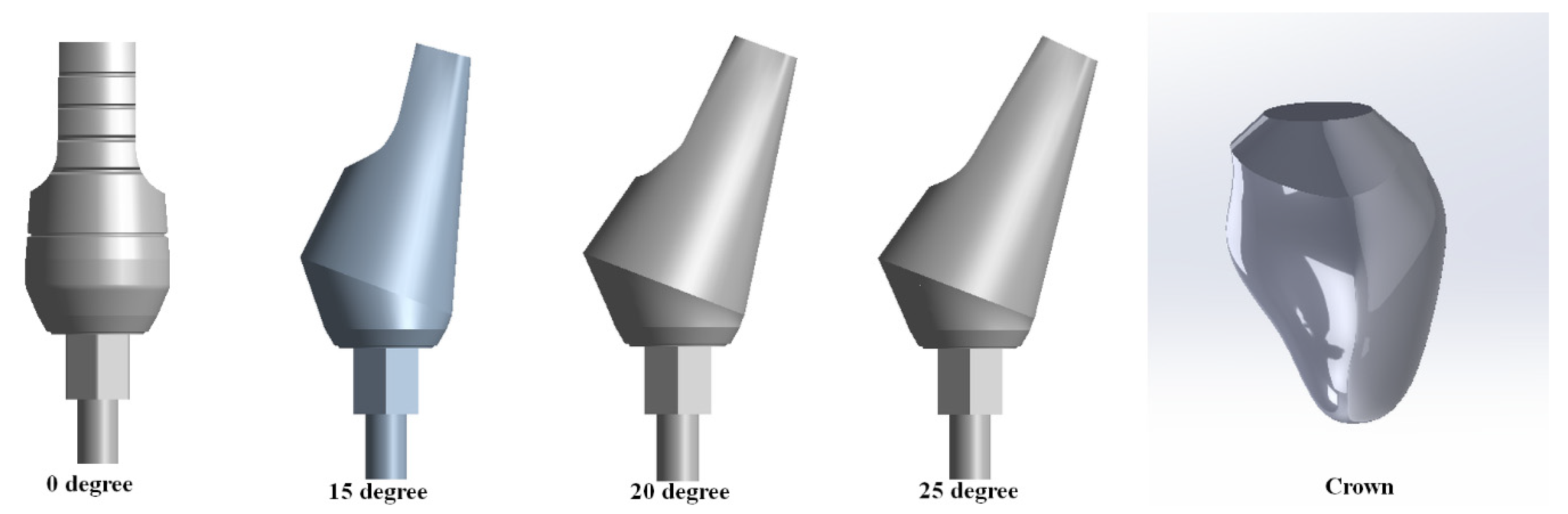
2.1. Modelling

Utilizing computed tomography (CT) scans of the mandible, we employed advanced imaging technology to generate three-dimensional (3D) models representing the intricate structures of these respective jawbones. Using 3D slicer-free, open-source software represents a cost-effective and accessible approach to constructing the models based on the CT scans. This software enables the conversion of CT scan images into detailed three-dimensional models of the maxilla bone (Figure 1a). A cross-sectional view of the complete dental components used in this study is shown in Figure 1b. The maxilla was modelled with a core of cancellous bone encapsulated inside cortical bone with a thickness of 2 mm. The implant model was developed based on the Alpha-Bio Tech product catalogue. The adopted model utilized an implant with a length of 11.5 mm and a diameter of 3.75 mm, as stated in the catalogue. To model the implant, CATIA 3D experience was used (Figure 2). The implant was tapered in dimensions, where A and B represent the upper and lower diameters in mm, and D represents the diameter of the implant used.
For the analysis, both straight and angled abutments were modelled. Figure 3 illustrates the CATIA 3D experience model of the abutments and crown, with the crown comprising zirconia material.

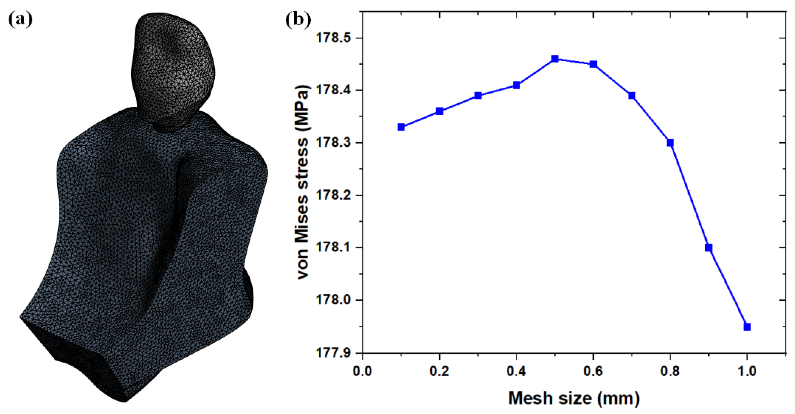
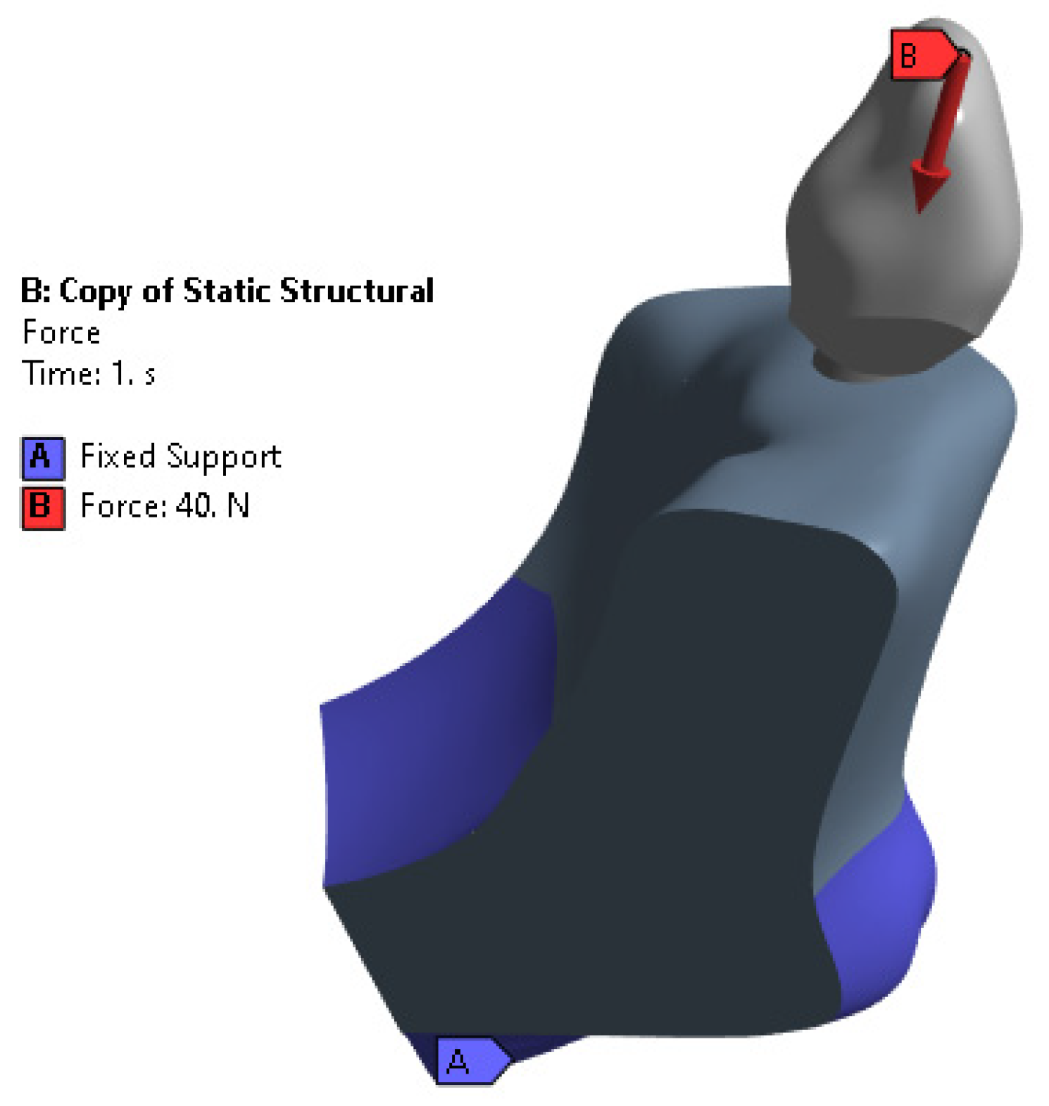
2.2. Meshing and Boundary Conditions
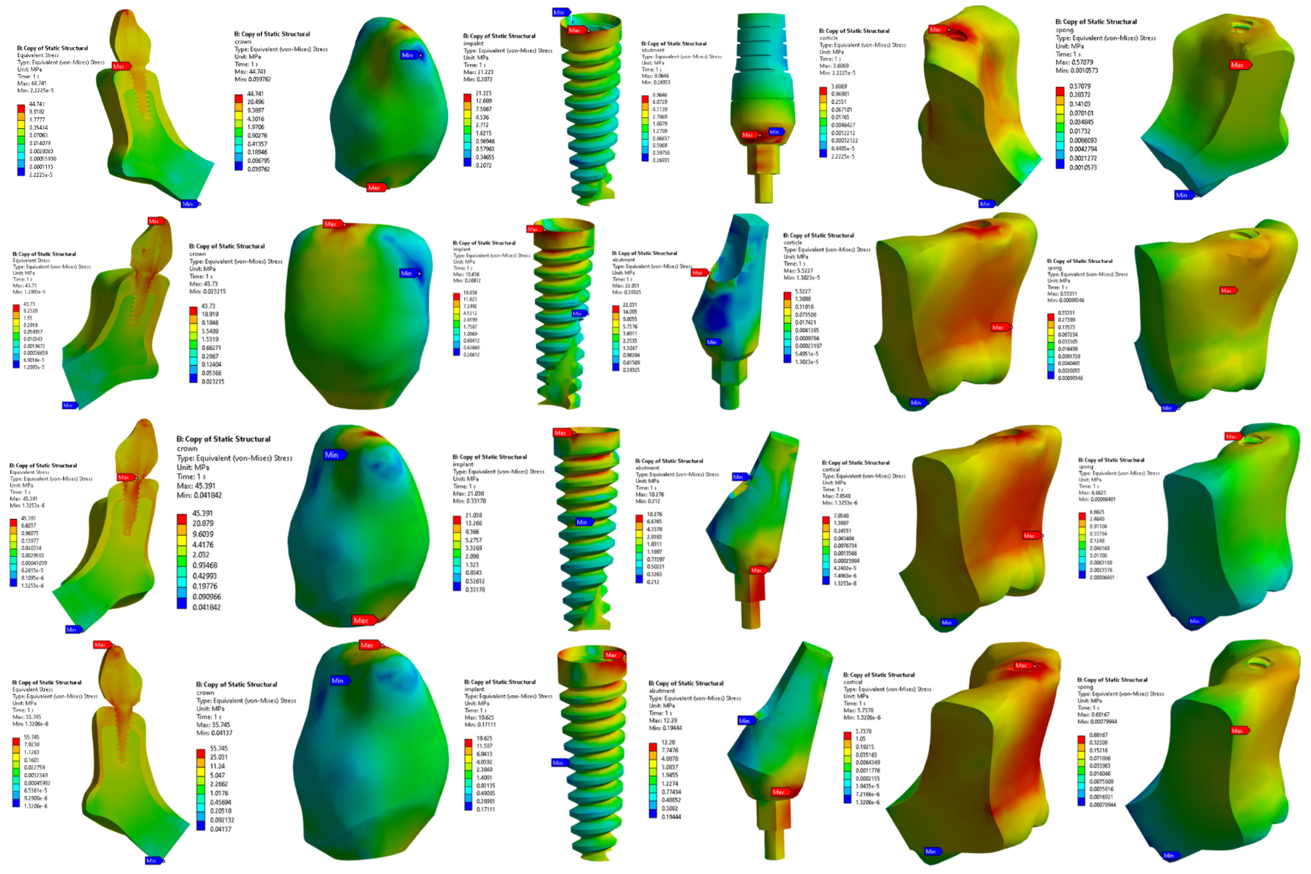
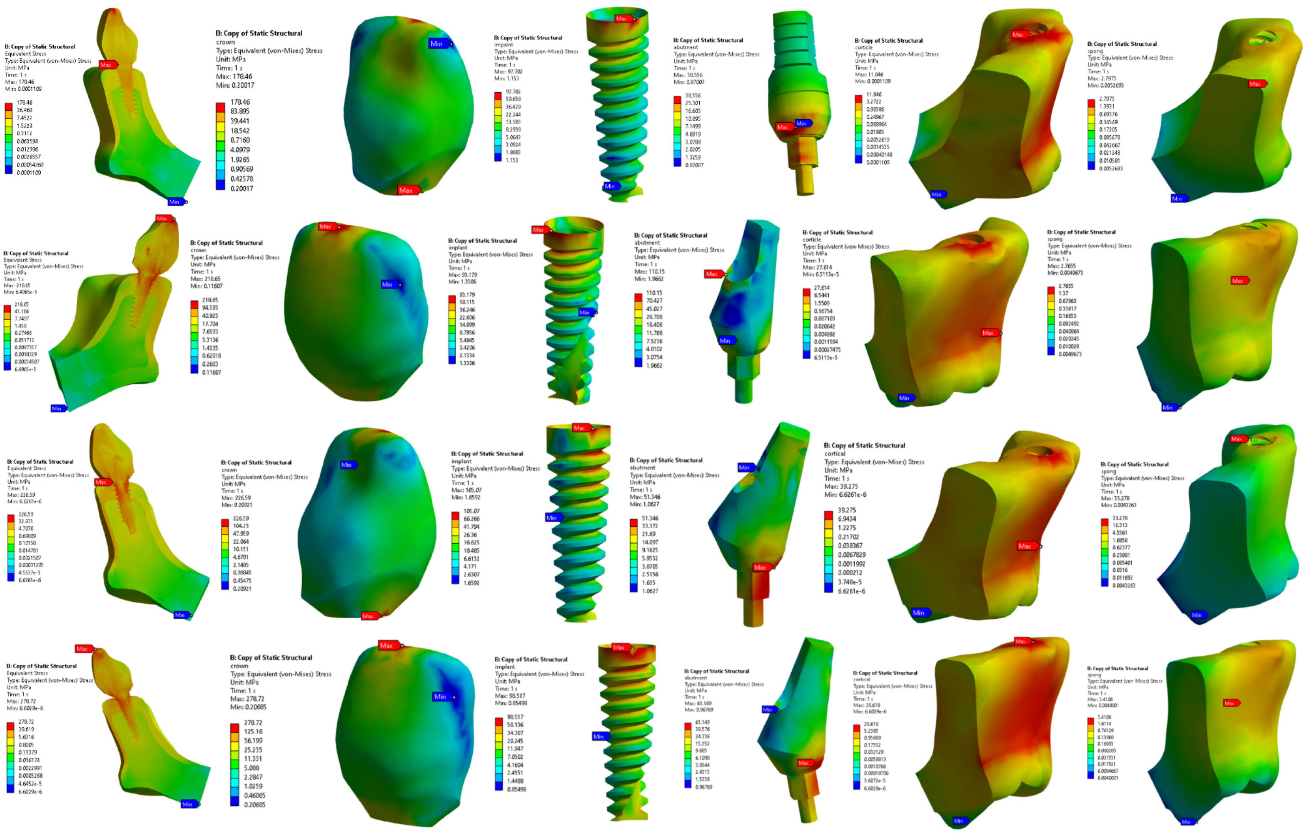
In this study, numerical models of the crown–abutment–implant–bone assembly were created using 4-node tetrahedral elements within ANSYS Workbench R2-2023, 3D finite element analysis software. Mesh convergence was carried out on the crown for the 200 N load case by varying the mesh size from 1 mm to 0.1 mm with an interval of 0.1 mm. It was observed that there were no significant differences in von Mises stresses, with a mesh size of less than 0.5 mm. Thus, a mesh size of 0.5 mm was finalized for further analysis. Figure 4b shows the mesh convergence study. The number of nodes and elements in the final model is given in Table 1. Figure 4a shows the meshed models of the implant structures.
For the analysis, the dental implant materials were assumed to be homogenous and elastic in behavior. The material properties were determined based on the literature source, as shown in Table 2. The mechanical properties employed in our study were chosen to precisely represent the material behavior within the simulation model.
For this study, the range of occlusal force was deliberately limited to a minimum of 40 N and a maximum of 200 N. This decision was based on previous research that highlighted the significant influence of the application angle of force on stress and strain patterns in the bone [12,22,23]. The load was applied in the vertical direction to the crown and the lower surface of the cortical bone was completely constrained, as shown in Figure 5. The contact between each component of the implant was assumed to be bound, as no sliding occurred between the implant components.

3. Results

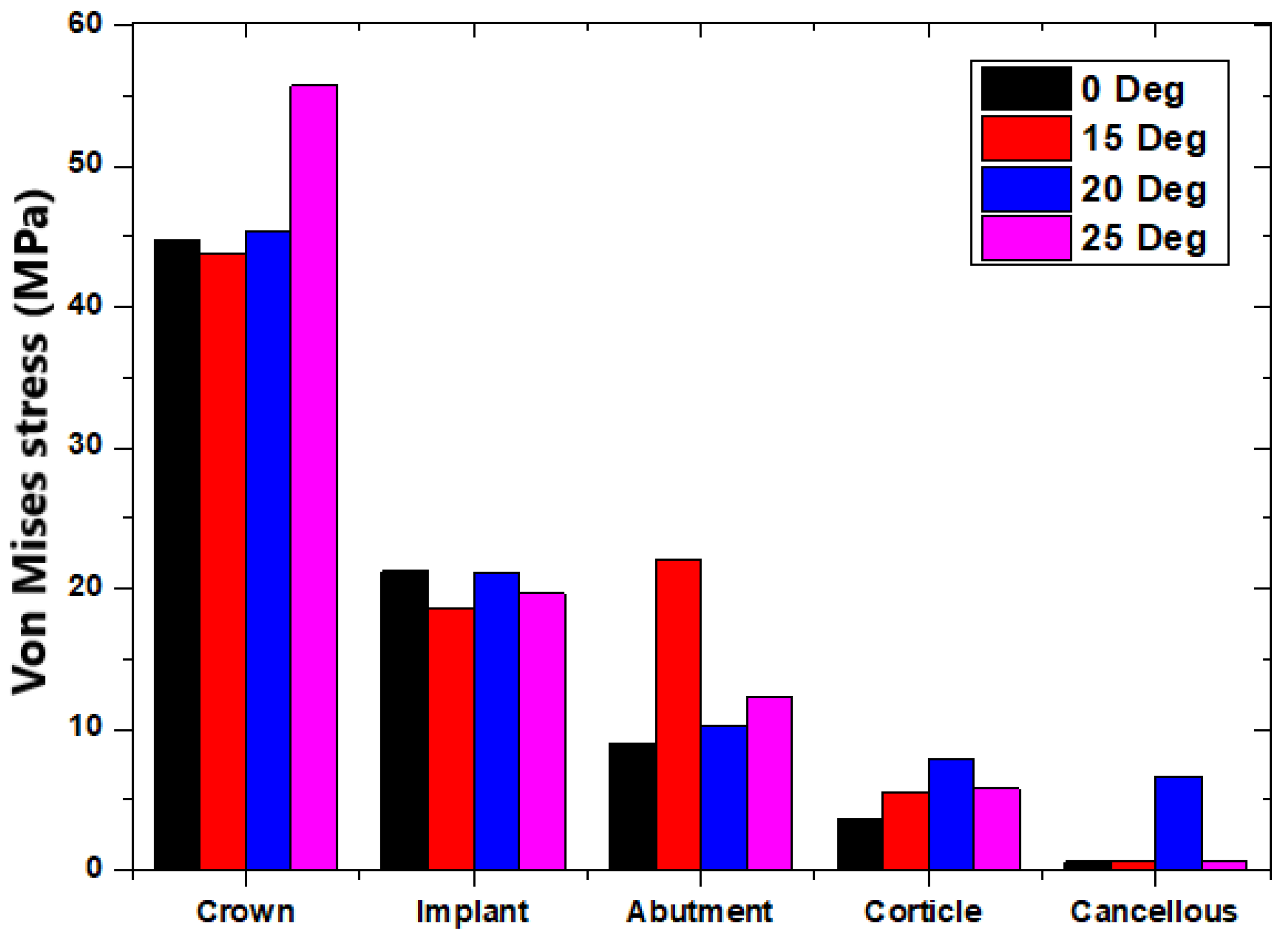
3.1. Stress Distribution in the Implant System

Figure 6 and Figure 7 show the stress distribution in the entire implant model for loads of 40 and 200 N, respectively. The highest stress concentrations were observed at the interfaces between the implant collar and the cortical bone [24]. This finding was significant as it highlighted areas where the structural integrity and load-bearing capacity of the implant system may be most challenged. Additionally, a stress effect was found on the portion of cortical bone and coronal cancellous bone [25]. The maximum stress concentrations at the interfaces between the implant collar and the cortical bone indicate that this region bears a substantial load during biomechanical loading. High stress concentrations at interfaces lead to issues such as material fatigue, implant loosening, and bone resorption. Under a load of 40 N, the maximum stress in the crown of the implant was 55.745 MPa; under a higher load of 200 N, the maximum stress increased to 278.72 MPa. These maximum stresses were exhibited by the implant crown for the 25° angulation of abutment. In the cortical and cancellous bone, the highest stresses recorded with a 20° abutment angle were 7.854 MPa and 39.275 MPa for the cortical bone, and 6.662 MPa and 33.278 MPa for the cancellous bone. At the implant–bone interface, the maximum stress observed at a 15° abutment angle was 22.276 MPa and 110.15 MPa. Stress distribution on both the implant shaft and implant neck showed that maximum stresses were located at the implant neck, irrespective of the forces applied; minimum stresses were located at the implant shaft [26]. The stress distribution in dental implants is notable due to its concentration in distinct regions. Stress is concentrated in the area near the first thread of the implant [27]. Angled abutments create non-axial forces on the implant, leading to an increase in the stress at the implant–bone interface. This could affect the stability of the implant and potentially compromise its long-term success.
The results obtained through simulation analysis in this study offer innovative insights into the stress distribution within dental implants, particularly focusing on angled abutments. Figure 6 and Figure 7 depict the stress distribution in the entire implant model under different loads, highlighting the highest stress concentrations at interfaces between the implant collar and the cortical bone. This finding is crucial as it underscores areas where the structural integrity and load-bearing capacity of the implant system may face significant challenges. Moreover, the study identified stress effects on both the cortical and coronal cancellous bone, with maximum stress concentrations observed at the implant collar interfaces. These findings are significant as they shed light on the biomechanical loading experienced by these regions, potentially leading to issues such as material fatigue, implant loosening, and bone resorption.

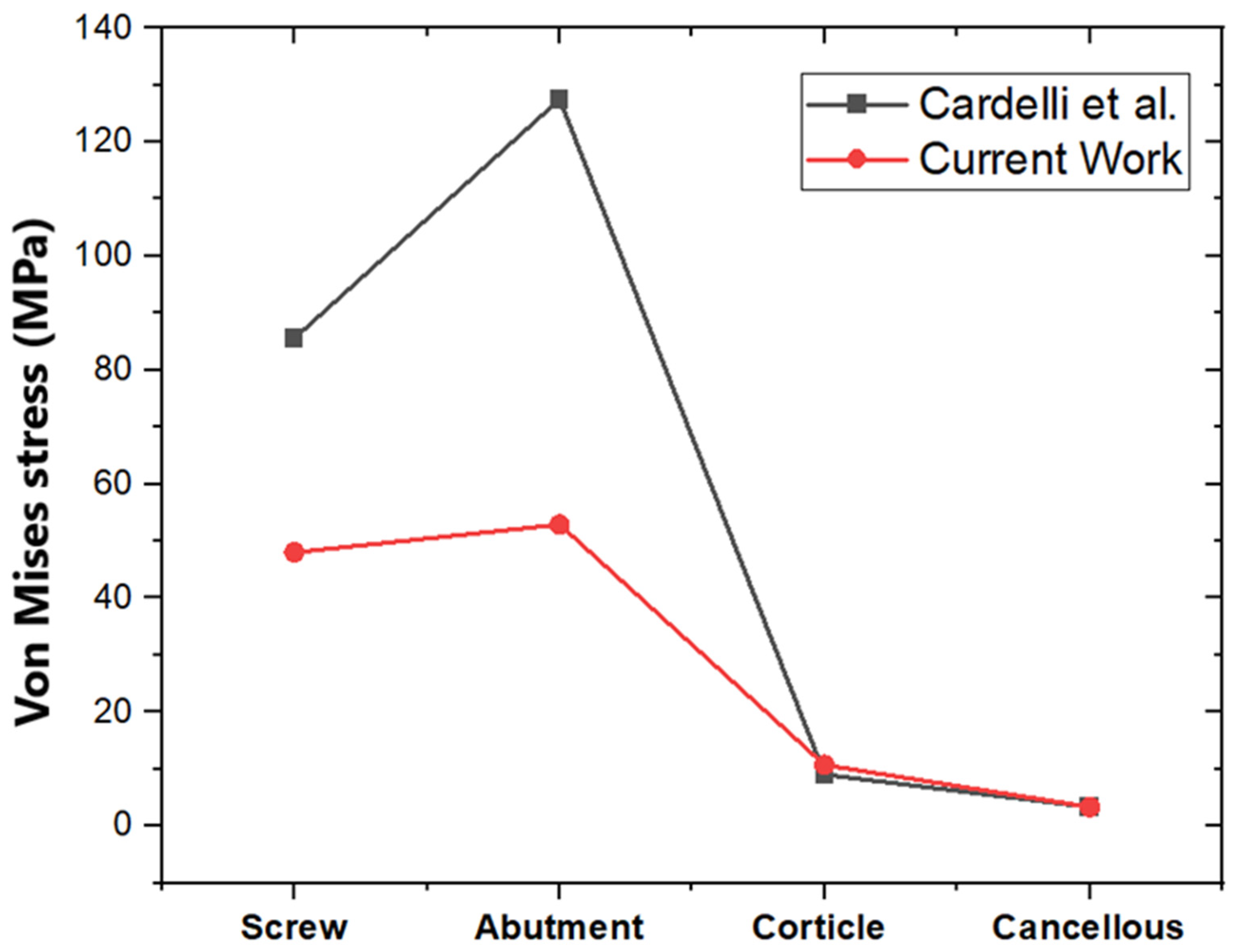
3.2. Validation of the Obtained Result with the Literature

To validate the results obtained in the current study, a comparison was performed with the findings obtained Cardelli et al. [28], in their article specifically focusing on loading conditions of 100 N. We obtained von Mises stress results for the loading conditions of 100 N, as presented in Figure 8. Importantly, the present study incorporated the crown in the simulations, whereas Cardelli et al. did not include the crown in their study. A dental crown serves as a protective cover for a damaged or weakened tooth, helping to restore its shape, strength, and functionality. When a tooth is crowned, it can withstand biting forces and chewing pressure better than an untreated tooth. Dental crowns play a crucial role in preserving the structural integrity of teeth and preventing further dental problems [29]. However, both cortical and cancellous bones exhibit nearly identical results, as shown in Figure 8. The potential variations in the values of screw and abutment, as with the presence or absence of a crown, can significantly influence stress distribution within the implant–bone system.

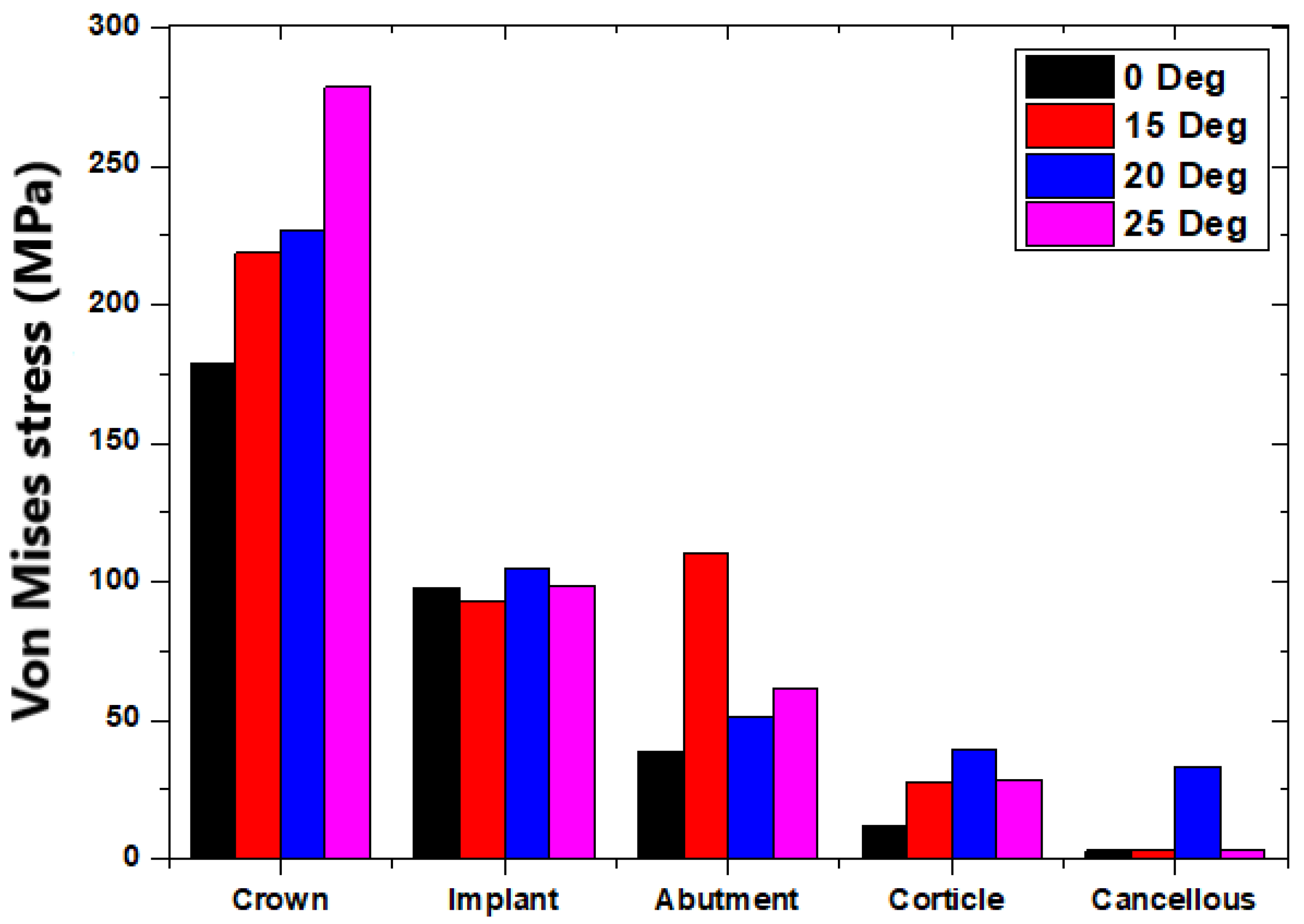
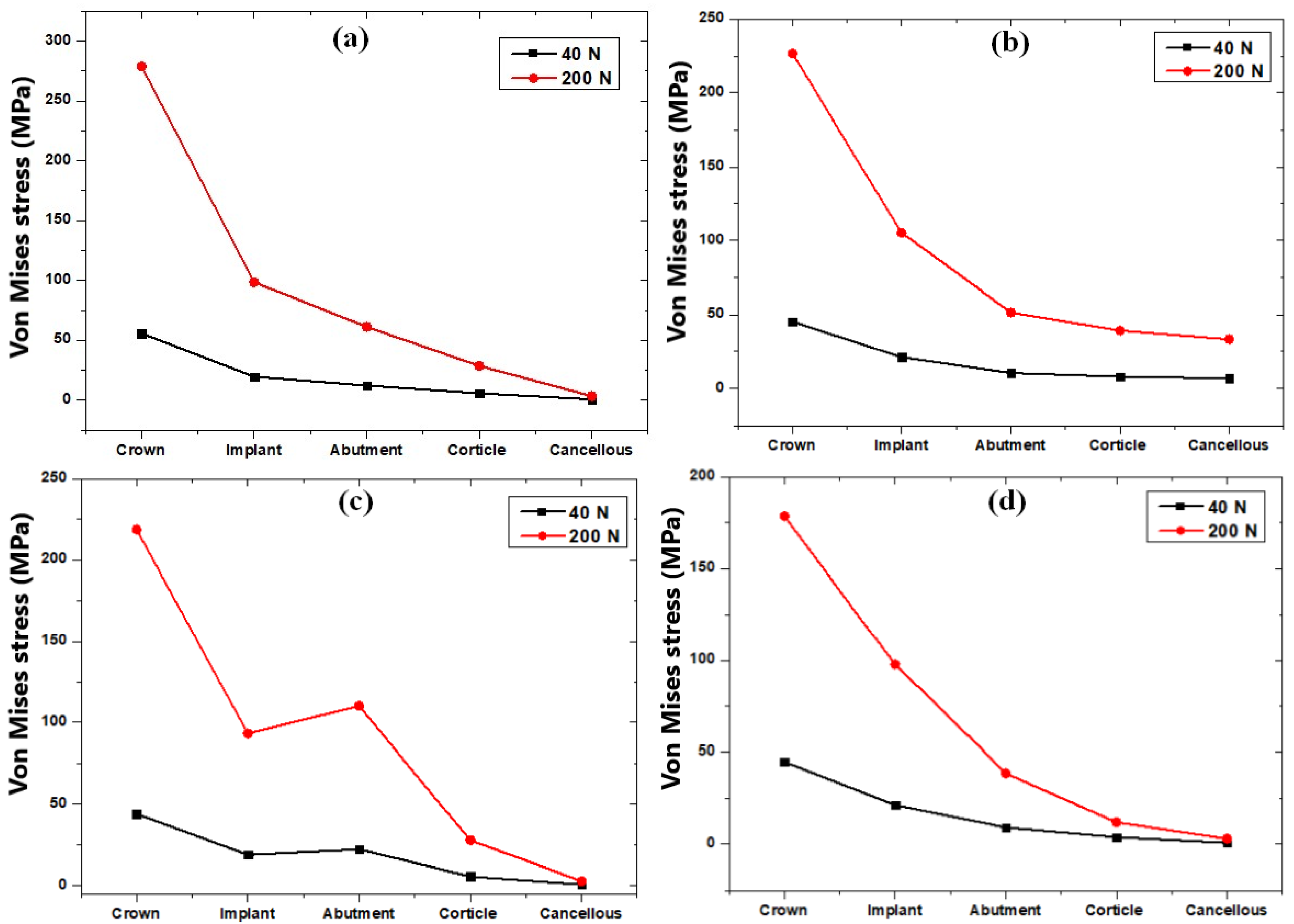
3.3. Comparison of Different Loading Conditions on the Angled Abutment

Figure 9 shows the maximum von Mises stresses in the dental structure for different abutment angles at a load of 40 N. It is clear from Figure 9 that the maximum stress of 55.74 MPa was obtained in the crown for an abutment angle of 25°. The minimum was obtained in the cancellous bone, as it took the stress at the end. When the 0°, 15° and 25° angulations were considered, there was a linear variation in the stress magnitude observed from the cancellous bone to the crown. However, for the 15° angulation of abutment, high stresses are obtained in the abutment as compared with the implant and the cortical bone. Similar stress behavior was observed in the load case of 200 N, as shown in Figure 10. The maximum stress of 287.72 MPa was obtained at a 25° abutment; the minimum stress was in the cancellous bone. This is because the cortical and cancellous bones receive the same force simultaneously, and as the abutment angle variation takes place, the stress transfer to the cancellous bone is minimized due to stress absorption by the cortical bone. The biomechanical phenomenon underscores the importance of considering abutment angles in implant design, as it directly impacts the stress distribution within the surrounding bone structures. The 15° abutment angle consistently resulted in higher stresses in the abutment compared with the implant and cortical bone, in both the 40 N and 200 N load cases.
Figure 11 presents different loads that affect the implant structure at abutment angles of 25°, 20°, 15°, and 0°, labelled as (a–d), respectively. The load cases were examined to gain insights into the impact of angulation on the implant assembly. The predominant observation in both load cases depicted in Figure 11a,b,d (angles of 25°, 20°, and 0°, respectively) is that the maximum stress consistently occurs in the crown. This aligns with the expected biomechanical scenario, given that the crown is the initial component that bears loads during the grinding of food. As the load transfers from the crown to the cancellous bone, a discernible reduction in stress levels is observed. Contrastingly, the implant structure at a 15° angle (Figure 11c) exhibits a non-linear pattern in stress distribution. Notably, the screw structure within the implant displays the second highest stress magnitude, particularly at the interfaces between the implant collar and the cortical bone.

4. Discussion

The present research aligns with the findings of Kapoor et al. [30], as both studies utilized finite element analysis to assess stress distribution within angulated implant structures and their adjacent bone regions under axial loading conditions. Consistent with the observations of Kapoor et al. [30], our study identified the highest stresses to be concentrated in the cortical bone surrounding the implant neck, particularly in cases involving angulated abutments at 25°, 20°, and 0°. Furthermore, our results indicate a similar trend of the maximum stress observed.
The investigation conducted by Bholla et al. [31] revealed a notable 26% increase in stress value in the interface of cortical bone and cancellous bone when comparing a 25° abutment with a 0° abutment. In our research, a similar trend was observed, demonstrating a 19.5% increase in stress value when comparing both 25° and 0° abutments. These findings contribute to the growing body of evidence indicating the influence of abutment angles on stress distribution within the implant and surrounding bone structures. Similar observations were also reported by Kao et al. [32].
In the studies conducted by Clelland et al. [33] and Papavasiliou et al. [34], the simulation results demonstrated that stresses were concentrated in the cortical bone, and the magnitude of these stresses increased with increases in the abutment angulation. Interestingly, our research yielded similar results, with observed increases in stress values associated with higher abutment angulations [35,36,37,38]. Baggi et al. [19] showed that the implant neck bears the maximum load due to contact stress. The presence of a stiffer cancellous bone proves advantageous by effectively reducing stress concentrations in the cervical area surrounding the terminal abutment, where stresses typically reach their peak. The complex interplay between bone biomechanics and implant structures emphasizes the importance of considering bone characteristics in the overall assessment of stress dynamics around dental implants. Our findings indicate that stress is concentrated in the area near the first thread of the implant, emphasizing the significance of this region in terms of mechanical loading. Additionally, there is a concentration of stress in the bone around the implant neck. Similar findings have been reported by Mahajan et al. [39].

5. Conclusions

The outcomes of our studies align with and substantiate certain evidence in the literature documenting bone resorption, specifically at the level of the implant neck and near the cortical bone. The stress concentrations identified in our research, notably in the area near the first thread and around the implant neck, correspond to regions where clinical evidence has reported bone resorption. The heightened stresses at the interfaces of the implant collar and cortical bone underscore potential areas of concern, warranting detailed examinations of structural integrity and biomechanical performance. The increased stresses of pre-angled abutments at the coronal zone may have implications for the long-term stability and health of the implant–bone interface. By leveraging FEA, researchers can assess and optimize the performance of proposed designs, contributing to the ongoing evolution of implant technologies aimed at minimizing stress-related issues and improving the overall success and longevity of dental implants.

Author Contributions

Conceptualization, L.G.K., C.K.N. and A.E.; methodology, A.E. and N.S.; software, L.G.K. and C.K.N.; validation, L.G.K., C.K.N. and N.S.; formal analysis, L.G.K.; investigation, C.K.N. and L.G.K.; resources, M.F., D.D.S., A.E. and N.S.; data curation, L.G.K. and C.K.N.; writing—original draft preparation, C.K.N. and L.G.K.; writing—review and editing, L.G.K., N.S., A.E. and N.S.; visualization, C.K.N., M.F. and D.D.S.; supervision, M.F. and D.D.S.; project administration, L.G.K. All authors have read and agreed to the published version of the manuscript.

Funding

This research received no external funding.

Institutional Review Board Statement

Not applicable.

Informed Consent Statement

Not applicable.

Data Availability Statement

Data are contained within the article.

Acknowledgments

The authors would like to thank the Department of Aeronautical and Automobile Engineering, Manipal Institute of Technology Manipal, Manipal Academy of Higher Education, Manipal, India, for providing the computing resources to carry out this study.

Conflicts of Interest

The authors declare no conflicts of interest.

References

  1. Shortall, A.C.; Shaini, F.J. A study into the performance of a gallium-based restorative material. Br. Dent. J. 2000, 189, 306. [Google Scholar] [CrossRef]
  2. Shehab, N.M.; Abdelhady, A.A.; Noaman, K.M.; Tawfeek, H.E.M. 3D finite element analysis assessment of maxillary premolar restored with various restorative materials. Int. J. Health Sci. 2022, 6, 907–920. [Google Scholar] [CrossRef]
  3. Pacheco, R.R.; Vitti, R.P.; Andrada, A.C.; Martins, C.M.; Catelan, A.; Khurshid, Z. Restorative materials used in endodontics. In Biomaterials in Endodontics; Elsevier: Amsterdam, The Netherlands, 2022; pp. 99–112. [Google Scholar]
  4. Frese, C.; Leciejewski, F.; Specht, R.; Wohlrab, T.; Büsch, C.; Boemicke, W.; Probst, K.; Katsikogianni, E.N.; Wolff, D. The dental esthetic screening index: A new tool for assessment of dento-facial esthetics in restorative dentistry. J. Esthet. Restor. Dent. 2019, 31, 572–582. [Google Scholar] [CrossRef] [PubMed]
  5. Saeed, F.; Muhammad, N.; Khan, A.S.; Sharif, F.; Rahim, A.; Ahmad, P.; Irfan, M. Prosthodontics dental materials: From conventional to unconventional. Mater. Sci. Eng. C 2020, 106, 110167. [Google Scholar] [CrossRef]
  6. Le Révérend, B.J.D.; Edelson, L.R.; Loret, C. Anatomical, functional, physiological and behavioural aspects of the development of mastication in early childhood. Br. J. Nutr. 2014, 111, 403–414. [Google Scholar] [CrossRef]
  7. Heinemann, F.; Mundt, T.; Biffar, R. Retrospective evaluation of temporary cemented, tooth and implant supported fixed partial dentures. J. Craniomaxillofac. Surg. 2006, 34 (Suppl. 2), 86–90. [Google Scholar] [CrossRef]
  8. Mozaffari, A.; Hashtbaran, D.; Moghadam, A.; Aalaei, S. Stress Distribution in Peri-implant Bone in the Replacement of Molars with One or Two Implants: A Finite Element Analysis. J. Dent. 2023, 24, 132–137. [Google Scholar] [CrossRef]
  9. Hebel, K.; Gajjar, R.; Hofstede, T. Single-tooth replacement: Bridge vs. implant-supported restoration. J. Can. Dent. Assoc. 2000, 66, 435–438. [Google Scholar]
  10. Coutsiers Morell, G.F.; Berlin-Broner, Y.; Flores-Mir, C.; Heo, G. Tooth and root size as determined from 0.25- and 0.30-mm voxel size cone-beam CT imaging when contrasted to micro-CT scans (0.06 mm): An ex vivo study. J. Orthod. 2022, 49, 174–178. [Google Scholar] [CrossRef] [PubMed]
  11. Xia, Z.; Gan, Y.; Chang, L.; Xiong, J.; Zhao, Q. Individual tooth segmentation from CT images scanned with contacts of maxillary and mandible teeth. Comput. Methods Programs Biomed. 2017, 138, 1–12. [Google Scholar] [CrossRef] [PubMed]
  12. Tian, K.; Chen, J.; Han, L.; Yang, J.; Huang, W.; Wu, D. Angled abutments result in increased or decreased stress on surrounding bone of single-unit dental implants: A finite element analysis. Med. Eng. Phys. 2012, 34, 1526–1531. [Google Scholar] [CrossRef]
  13. Mesnard, M.; Ramos, A.; Ballu, A.; Morlier, J.; Cid, M.; Simoes, J.A. Biomechanical analysis comparing natural and alloplastic temporomandibular joint replacement using a finite element model. J. Oral Maxillofac. Surg. 2011, 69, 1008–1017. [Google Scholar] [CrossRef] [PubMed]
  14. Turkyilmaz, I. Restoring severely angled implants with custom abutments and a screw-retained fixed dental prosthesis. J. Dent. Sci. 2019, 14, 107–108. [Google Scholar] [CrossRef] [PubMed]
  15. Gutmann, C.; Shaikh, N.; Shenoy, B.S.; Shaymasunder Bhat, N.; Keni, L.G. Chethan Wear estimation of hip implants with varying chamfer geometry at the trunnion junction: A finite element analysis. Biomed. Phys. Eng. Express 2023, 9, 035004. [Google Scholar] [CrossRef] [PubMed]
  16. Shaikh, N.; Shenoy, B.S.; Bhat, N.S.; Shetty, S.; Chethan, K.N. Wear estimation at the contact surfaces of oval shaped hip implants using finite element analysis. Cogent Eng. 2023, 10, 222298. [Google Scholar] [CrossRef]
  17. Göktaş, H.; Subaşi, E.; Uzkut, M.; Kara, M.; Biçici, H.; Shirazi, H.; Chethan, K.N.; Mihçin, Ş. Optimization of Hip Implant Designs Based on Its Mechanical Behaviour; Springer: Berlin/Heidelberg, Germany, 2022; pp. 37–43. [Google Scholar]
  18. Keni, L.G.; Hayoz, M.J.; Mohammad, S.; Khader, A.; Hegde, P.; Prakashini, K.; Tamagawa, M.; Satish Shenoy, B.; Hameed, B.M.Z.; Zuber, M. Computational Flow Analysis of a Single Peristaltic Wave Propagation in the Ureter. Comput. Methods Programs Biomed. 2021, 210, 106378. [Google Scholar] [CrossRef] [PubMed]
  19. Baggi, L.; Cappelloni, I.; Di Girolamo, M.; Maceri, F.; Vairo, G. The influence of implant diameter and length on stress distribution of osseointegrated implants related to crestal bone geometry: A three-dimensional finite element analysis. J. Prosthet. Dent. 2008, 100, 422–431. [Google Scholar] [CrossRef]
  20. Sannino, G.; Pozzi, A.; Schiavetti, R.; Barlattani, A. Stress distribution on a three-unit implant-supported zirconia framework. A 3D finite element analysis and fatigue test. Oral Implantol. 2012, 5, 11–20. [Google Scholar]
  21. Cibirka, R.M.; Razzoog, M.E.; Lang, B.R.; Stohler, C.S. Determining the force absorption quotient for restorative materials used in implant occlusal surfaces. J. Prosthet. Dent. 1992, 67, 361–364. [Google Scholar] [CrossRef]
  22. Pellizzer, E.P.; Verri, F.R.; de Moraes, S.L.D.; Falcón-Antenucci, R.M.; de Carvalho, P.S.P.; Noritomi, P.Y. Influence of the Implant Diameter With Different Sizes of Hexagon: Analysis by 3-Dimensional Finite Element Method. J. Oral Implantol. 2013, 39, 425–431. [Google Scholar] [CrossRef]
  23. Morneburg, T.R.; Pröschel, P.A. Predicted incidence of occlusal errors in centric closing around arbitrary axes. Int. J. Prosthodont. 2002, 15, 358–364. [Google Scholar]
  24. Costa, C.; Peixinho, N.; Silva, J.P.; Carvalho, S. Study and characterization of the crest module design: A 3D finite element analysis. J. Prosthet. Dent. 2015, 113, 541–547. [Google Scholar] [CrossRef]
  25. Faegh, S.; Müftü, S. Load transfer along the bone-dental implant interface. J. Biomech. 2010, 43, 1761–1770. [Google Scholar] [CrossRef]
  26. Leblebicioğlu Kurtuluş, I.; Kilic, K.; Bal, B.; Kilavuz, A. Finite Element Analysis of the Stress Distribution Associated With Different Implant Designs for Different Bone Densities. J. Prosthodont. 2022, 31, 614–622. [Google Scholar] [CrossRef] [PubMed]
  27. Datte, C.-E.; Tribst, J.-P.-M.; Dal Piva, A.-M.O.; Nishioka, R.-S.; Bottino, M.-A.; Evangelhista, A.-D.M.; de Monteiro, F.M.; Borges, A.-L.-S. Influence of different restorative materials on the stress distribution in dental implants. J. Clin. Exp. Dent. 2018, 10, e439–e444. [Google Scholar] [CrossRef] [PubMed]
  28. Cardelli, P.; Montani, M.; Gallio, M.; Biancolini, M.; Brutti, C.; Barlattani, A. Angulated abutments and perimplants stress: F.E.M. analysis. Oral Implantol. 2009, 2, 3–10. [Google Scholar]
  29. Alemayehu, D.B.; Jeng, Y.R. Three-dimensional finite element investigation into effects of implant thread design and loading rate on stress distribution in dental implants and anisotropic bone. Materials 2021, 14, 6974. [Google Scholar] [CrossRef] [PubMed]
  30. Kapoor, S.; Rodrigues, S.; Mahesh, M.; Shetty, T.; Pai, U.; Saldanha, S.; Hedge, P.; Shenoy, S. Evaluation of Stress Generated with Different Abutment Materials and Angulations under Axial and Oblique Loading in the Anterior Maxilla: Three-Dimensional Finite Element Analysis. Int. J. Dent. 2021, 2021, 9205930. [Google Scholar] [CrossRef] [PubMed]
  31. Jo, L.; Vamsi, K.; Ariga, P.; Bholla, P. Influence of occlusal loading on stress patterns at the bone-implant interface by angulated abutments in the anterior maxilla: A three-dimensional finite-element study. J. Dent. Implant. 2014, 4, 3. [Google Scholar] [CrossRef]
  32. Kao, H.-C.; Gung, Y.-W.; Chung, T.-F.; Hsu, M.-L. The influence of abutment angulation on micromotion level for immediately loaded dental implants: A 3-D finite element analysis. Int. J. Oral Maxillofac. Implants 2008, 23, 623–630. [Google Scholar]
  33. Clelland, N.L.; Lee, J.K.; Bimbenet, O.C.; Brantley, W.A. A Three-Dimensional Finite Element Stress Analysis of Angled Abutments for an Implant Placed in the Anterior Maxilla. J. Prosthodont. 1995, 4, 95–100. [Google Scholar] [CrossRef] [PubMed]
  34. Papavasiliou, G.; Kamposiora, P.; Bayne, S.C.; Felton, D.A. Three-dimensional finite element analysis of stress-distribution around single tooth implants as a function of bony support, prosthesis type, and loading during function. J. Prosthet. Dent. 1996, 76, 633–640. [Google Scholar] [CrossRef] [PubMed]
  35. Wu, D.; Tian, K.; Chen, J.; Jin, H.; Huang, W.; Liu, Y. A Further Finite Element Stress Analysis of Angled Abutments for an Implant Placed in the Anterior Maxilla. Comput. Math. Methods Med. 2015, 2015, 560645. [Google Scholar] [CrossRef] [PubMed]
  36. Chun, H.-J.; Shin, H.-S.; Han, C.-H.; Lee, S.-H. Influence of implant abutment type on stress distribution in bone under various loading conditions using finite element analysis. Int. J. Oral Maxillofac. Implants 2006, 21, 195–202. [Google Scholar]
  37. Lin, C.-L.; Wang, J.-C.; Ramp, L.C.; Liu, P.-R. Biomechanical response of implant systems placed in the maxillary posterior region under various conditions of angulation, bone density, and loading. Int. J. Oral Maxillofac. Implants 2008, 23, 57–64. [Google Scholar]
  38. Badalia, I.; Kumar, M.; Bansal, A.; Mehra, S.; Batra, R. Evaluation of Stress Patterns in Bone Around Implants for Different Abutment Angulations Under Axial and Oblique Loading in Anterior Maxillary Region—A Finite Element Analysis. Dent. J. Adv. Stud. 2020, 8, 60–64. [Google Scholar] [CrossRef]
  39. Mahajan, S.; Patil, R. Application of finite element analysis to optimizing dental implant. Int. Res. J. Eng. Technol. 2016, 03, 850–856. [Google Scholar]
Figure 1. (a) Three-dimensional model from the CT scans using a 3D Slicer; (b) cross-sectional view of the dental component assembly.
Prosthesis 06 00024 g001
Figure 2. Implant model: (a) catalogue model; (b) drafting view of the 3D model; (c) 3D model.
Prosthesis 06 00024 g002
Figure 3. Angled abutment and crown.
Prosthesis 06 00024 g003
Figure 4. (a) Meshed model; (b) mesh convergence graph.
Prosthesis 06 00024 g004
Figure 5. Boundary conditions.
Prosthesis 06 00024 g005
Figure 6. Implant structure stress distribution for the 40 N load case.
Prosthesis 06 00024 g006
Figure 7. Implant structure stress distribution for the 200 N load case.
Prosthesis 06 00024 g007
Figure 8. Validation of the obtained result with Cardelli et al. [28].
Prosthesis 06 00024 g008
Figure 9. The 40 N load case comparison for different abutment angles.
Prosthesis 06 00024 g009
Figure 10. The 200 N load case comparison for different abutment angles.
Prosthesis 06 00024 g010
Figure 11. Load case comparison for abutment angles: (a) 25° (b) 20° (c) 15°, and (d) 0°.
Prosthesis 06 00024 g011
Table 1. Details of the models and corresponding nodes and elements for each model.
ComponentsNodeElements
Crown47,57531,658
Abutment91,61463,194
Implant55,41635,432
Cortical bone363,346251,040
Cancellous bone162,859114,354
Table 2. Mechanical properties of the implant structure.
Anatomic StructureModulus of Elasticity (GPa)Poisson’s RatioReferences
Implant1100.35[19]
Abutment1100.28[19]
Crown structure 2100.33[20]
Cortical bone 13.70.3[19]
Cancellous Bone1.100.3[21]
Disclaimer/Publisher’s Note: The statements, opinions and data contained in all publications are solely those of the individual author(s) and contributor(s) and not of MDPI and/or the editor(s). MDPI and/or the editor(s) disclaim responsibility for any injury to people or property resulting from any ideas, methods, instructions or products referred to in the content.

