
Reimagining Prosthetic Control: A Novel Body-Powered Prosthetic System for Simultaneous Control and Actuation


Abstract
:1. Introduction
2. Materials and Methods
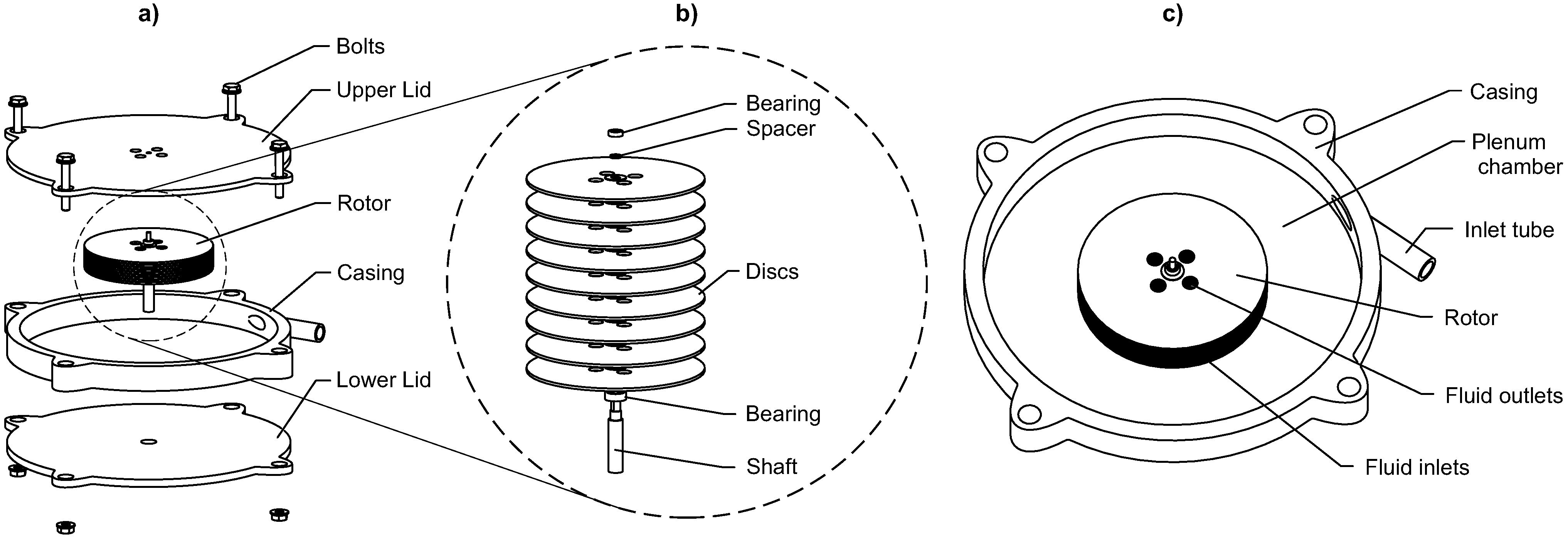
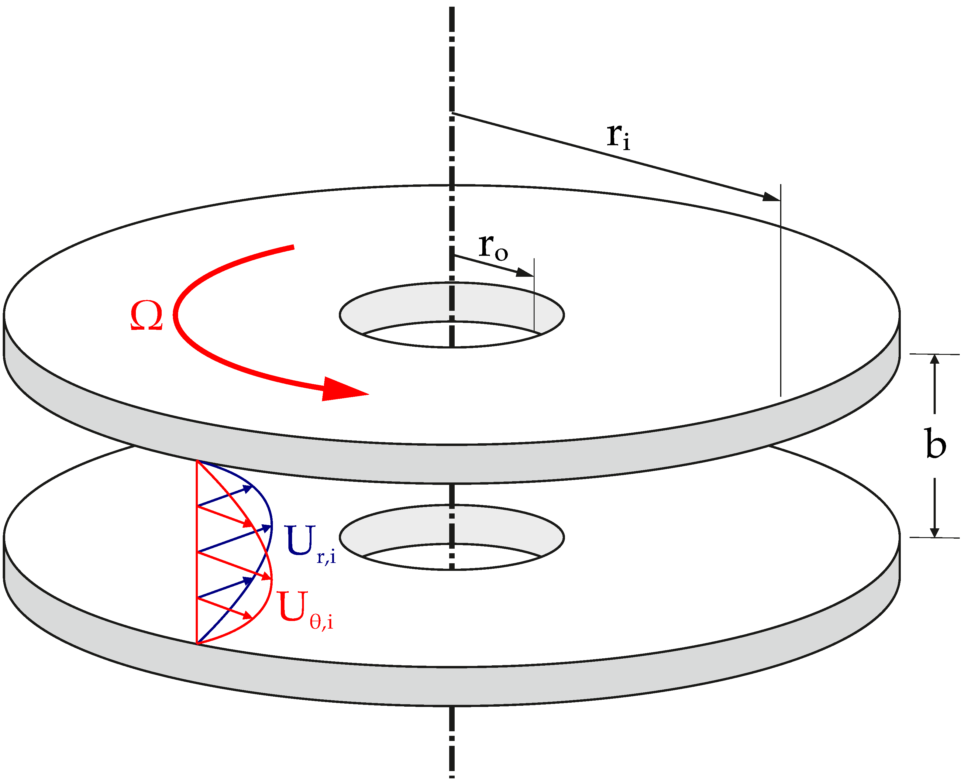
2.1. Turbine
2.2. Tesla Turbine Model
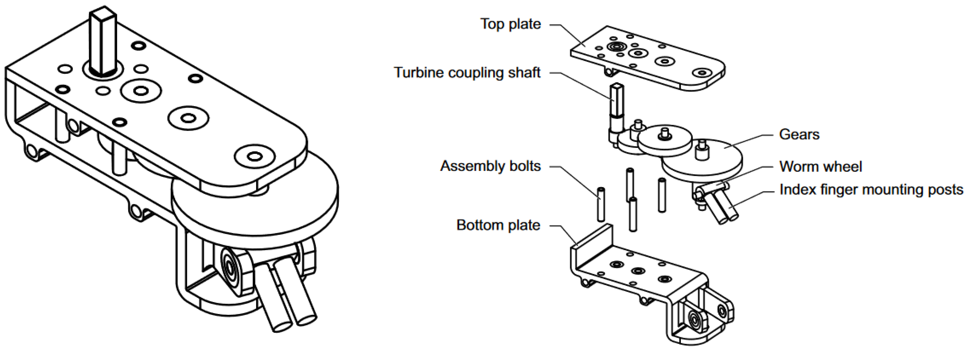
2.3. Transmission
3. Results
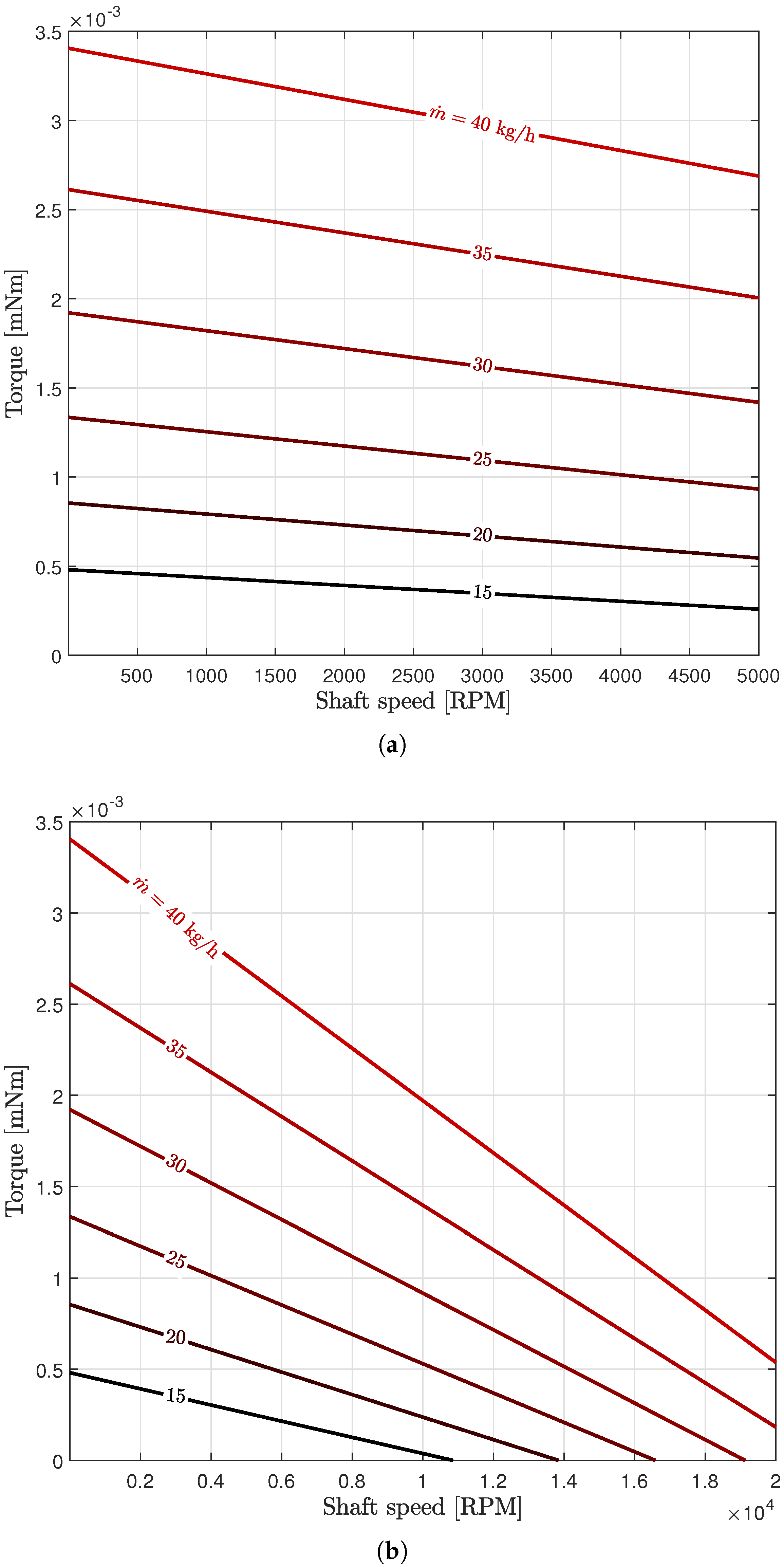
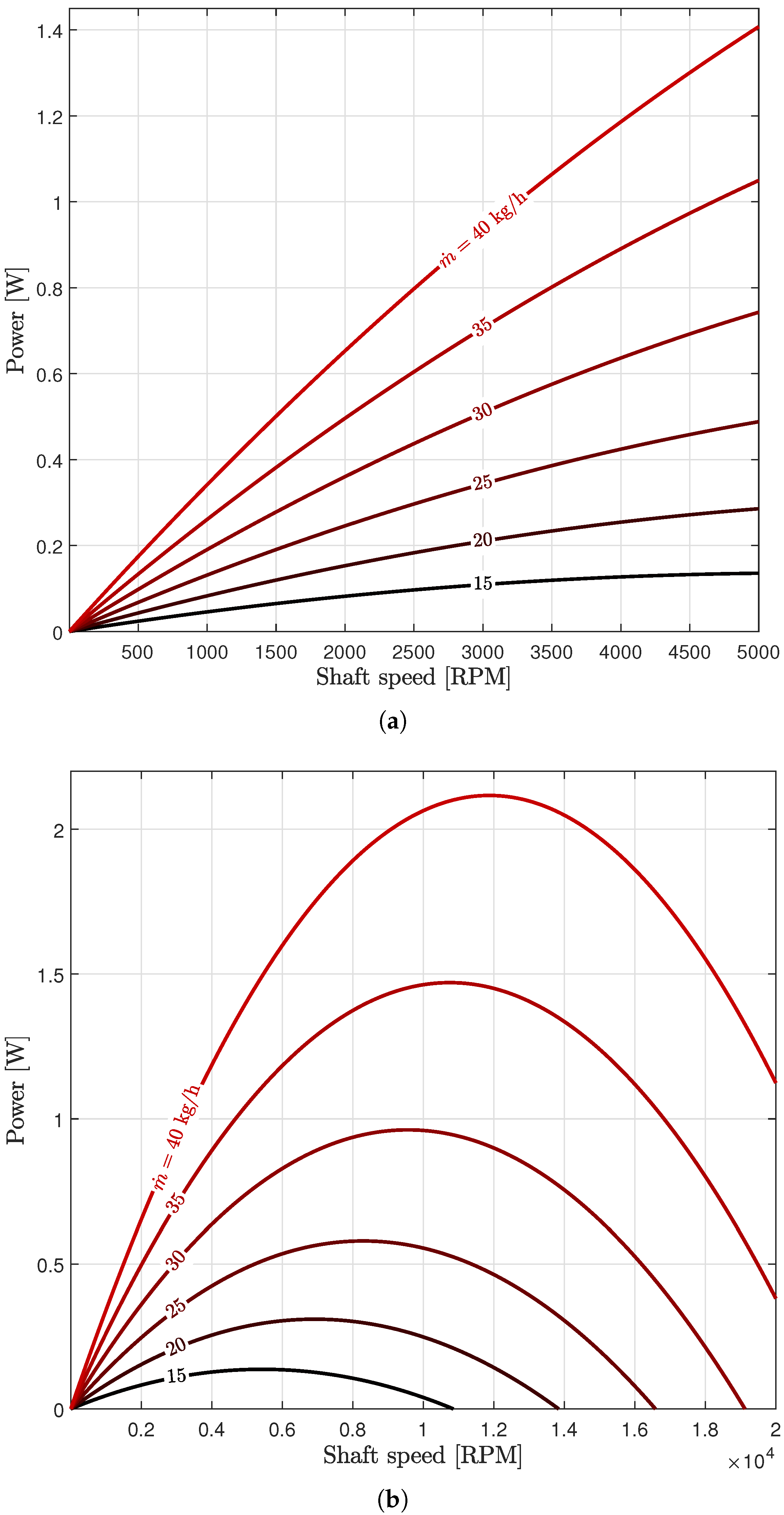
3.1. Turbine
3.2. Transmission
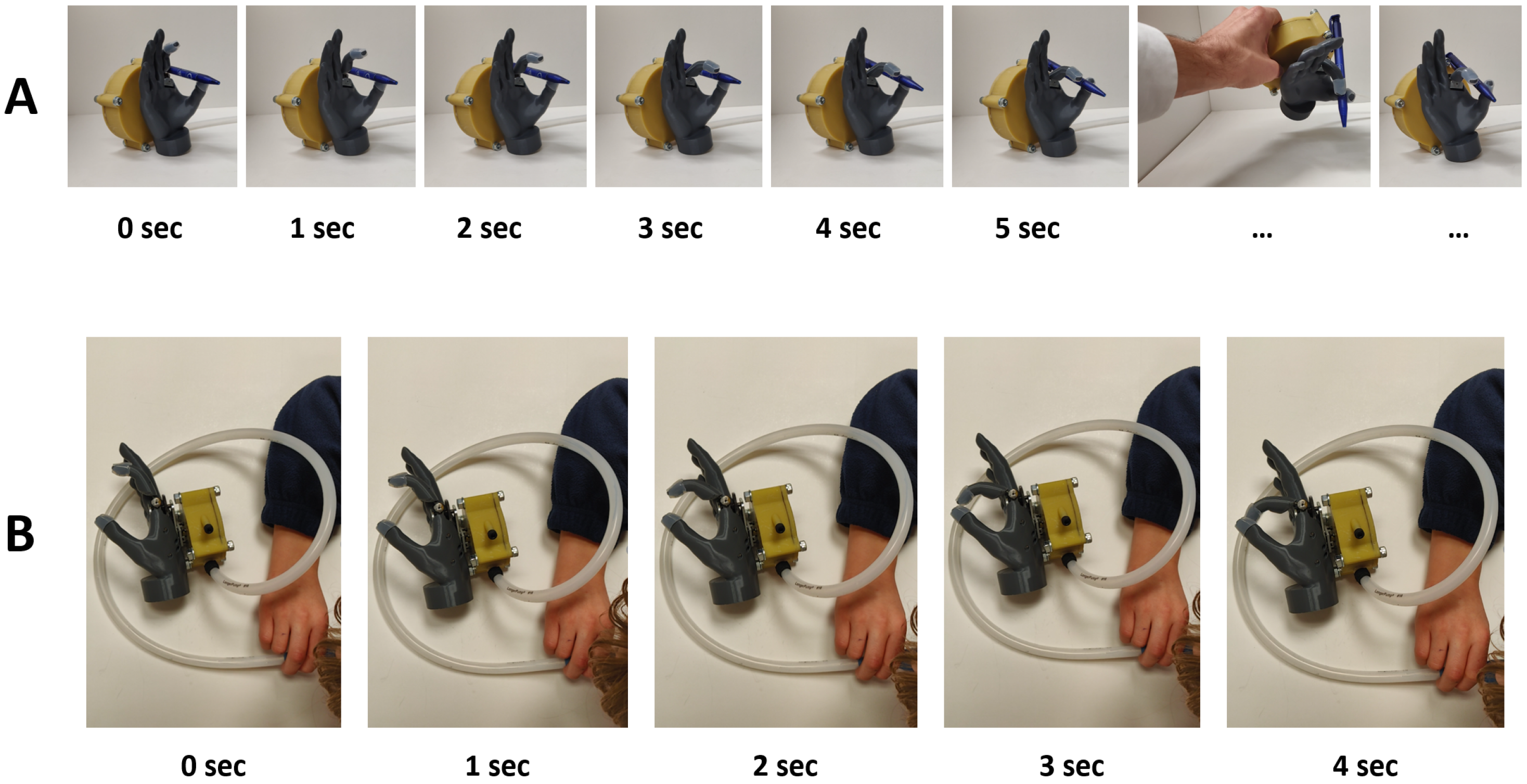
3.3. Demonstration—Preliminary User Testing
4. Discussion
5. Conclusions
6. Patents
Supplementary Materials
Author Contributions
Funding
Institutional Review Board Statement
Informed Consent Statement
Acknowledgments
Conflicts of Interest
Abbreviations
| ADL | Activity of daily living |
| BP | Body-powered (device) |
| CFD | Computational Fluid Dynamics |
| EP | Externally-powered (device) |
| MCP | Metacarpophalangeal (joint) |
| MSK | Musculoskeletal |
| NBDMs | Non-back-drivable mechanisms |
| QOL | Quality of life |
| RPM | Rotations per minute |
| TD | Terminal device |
| UE | Upper extremity |
| UL | Upper limb |
| VC | Voluntary closing |
| VO | Voluntary opening |
| ULPOM | Upper Limb Prosthetic Outcome Measures (Group) |
| WHO | World Health Organization |
| WHO—ICF | WHO—International Classification of Functioning, Disability, and Health |
References
- Stevens, P. Prosthetics in Resource-Limited Countries. The O&P EDGE, 2 June 2015. [Google Scholar]
- WHO. United States Department of Defense, and MossRehab Amputee Rehabilitation Program. In The Rehabilitation of People with Amputations; World Health Organization: Geneva, Switzerland, 2004. [Google Scholar]
- Bethge, M.; von Groote, P.; Giustini, A.; Gutenbrunner, C. The World Report on Disability: A challenge for rehabilitation medicine. Am. J. Phys. Med. Rehabil. 2014, 93, S4–S11. [Google Scholar] [CrossRef] [PubMed]
- Ramamurthy, P.H. Enabling and caring for children with limb loss. Paediatr. Child Health 2021, 31, 347–351. [Google Scholar] [CrossRef]
- Davids, J.R.; Wagner, L.V.; Meyer, L.C.; Blackhurst, D.W. Prosthetic management of children with unilateral congenital below-elbow deficiency. J. Bone Jt. Surg. 2006, 88, 1294–1300. [Google Scholar] [CrossRef]
- Landsberger, S.; Shaperman, J.; Setoguchi, Y.; Fite, R.; Lin, A.; Vargas, V.; McNeal, D. Child prosthetic hand design: No small challenge. In Proceedings of the Wescon/96, Anaheim, CA, USA, 22–24 October 1996; IEEE: Piscataway, NJ, USA, 1996; pp. 236–240. [Google Scholar]
- Hill, W.; Hermansson, L.M. Treatment for Children with Upper-Limb Differences in Various Parts of the World: Preliminary Findings. JPO J. Prosthetics Orthot. 2022. [Google Scholar] [CrossRef]
- Kuyper, M.A.; Breedijk, M.; Mulders, A.; Post, M.; Prevo, A. Prosthetic management of children in The Netherlands with upper limb deficiencies. Prosthetics Orthot. Int. 2001, 25, 228–234. [Google Scholar] [CrossRef]
- Shaperman, J.; Landsberger, S.E.; Setoguchi, Y. Early upper limb prosthesis fitting: When and what do we fit. JPO J. Prosthetics Orthot. 2003, 15, 11–17. [Google Scholar] [CrossRef]
- Krebs, D.E.; Edelstein, J.E.; Thornby, M.A. Prosthetic management of children with limb deficiencies. Phys. Ther. 1991, 71, 920–934. [Google Scholar] [CrossRef]
- Hashim, N.A.; Abd Razak, N.A.; Abu Osman, N.A.; Gholizadeh, H. Improvement on upper limb body-powered prostheses (1921–2016): A systematic review. Proc. Inst. Mech. Eng. Part H J. Eng. Med. 2018, 232, 3–11. [Google Scholar] [CrossRef]
- Simpson, D. The choice of control system for the multimovement prosthesis: Extended Physiological Proprioception (EPP). In The Control of Upper-Extremity Prostheses and Orthoses; Herberts, P., Kadefors, R., Magnusson, R., Petersen, I., Eds.; Charles C. Thomas: Springfield, IL, USA, 1974; pp. 146–150. [Google Scholar]
- Henson, A. What Are My Prosthetic Options Based on My Amputation Level? 2021. Available online: https://www.armdynamics.com/upper-limb-library/what-are-my-prosthetic-options-based-on-my-amputation-level (accessed on 12 May 2021).
- Gates, D.H.; Engdahl, S.M.; Davis, A. Recommendations for the Successful Implementation of Upper Limb Prosthetic Technology. Hand Clin. 2021, 37, 457–466. [Google Scholar] [CrossRef]
- Biddiss, E.A.; Chau, T.T. Upper limb prosthesis use and abandonment: A survey of the last 25 years. Prosthetics Orthot. Int. 2007, 31, 236–257. [Google Scholar] [CrossRef] [PubMed]
- Weir, R.; Sensinger, J.W.; Kutz, M. Design of artificial arms and hands for prosthetic applications. Biomed. Eng. Des. Handb. 2009, 2, 537–598. [Google Scholar]
- Dorrance, D.W. Artificial Hand. U.S. Patent 1,042,413, 29 October 1912. [Google Scholar]
- Zuo, K.J.; Olson, J.L. The evolution of functional hand replacement: From iron prostheses to hand transplantation. Plast. Surg. 2014, 22, 44–51. [Google Scholar] [CrossRef] [Green Version]
- Childress, D.S. Historical aspects of powered limb prostheses. Clin. Prosthetics Orthot. 1985, 9, 2–13. [Google Scholar]
- Borchardt, M.; Hartmann, K.; Leymann, R.; Schlesinger, S. Limb Substitutes and Labour Assistive Devices for War Casualties and Traumatic Injured Persons [In German: Ersatzglieder und Arbeitshilfen: Für Kriegsbeschädigte und Unfallverletzte]; Springer: Berlin, Germany, 1919; pp. 321–573. [Google Scholar]
- Muilenburg, A.L.; LeBlanc, M.A. Body-powered upper-limb components. In Comprehensive Management of the Upper-Limb Amputee; Springer: Berlin/Heidelberg, Germany, 1989; pp. 28–38. [Google Scholar]
- Meier, R.H. History of arm amputation, prosthetic restoration, and arm amputation rehabilitation. In Functional Restoration of Adults and Children with Upper Extremity Amputation; Demos Medical: New York, NY, USA, 2004; pp. 1–7. [Google Scholar]
- Piazza, C.; Grioli, G.; Catalano, M.; Bicchi, A. A century of robotic hands. Annu. Rev. Control. Robot. Auton. Syst. 2019, 2, 1–32. [Google Scholar] [CrossRef]
- Belter, J.T.; Reynolds, B.C.; Dollar, A.M. Grasp and force based taxonomy of split-hook prosthetic terminal devices. In Proceedings of the 2014 36th Annual International Conference of the IEEE Engineering in Medicine and Biology Society, Chicago, IL, USA, 26–30 August 2014; IEEE: Piscataway, NJ, USA, 2014; pp. 6613–6618. [Google Scholar]
- Belter, J.T.; Segil, J.L.; SM, B. Mechanical design and performance specifications of anthropomorphic prosthetic hands: A review. J. Rehabil. Res. Dev. 2013, 50, 599. [Google Scholar] [CrossRef]
- Chadwell, A.; Kenney, L.; Howard, D.; Ssekitoleko, R.T.; Nakandi, B.T.; Head, J. Evaluating reachable workspace and user control over prehensor aperture for a body-powered prosthesis. IEEE Trans. Neural Syst. Rehabil. Eng. 2020, 28, 2005–2014. [Google Scholar] [CrossRef]
- Nagaraja, V.H.; Cheng, R.; Slater, D.H.; Thompson, M.S.; Bergmann, J.H. Upper-Limb Prosthetic Maintenance Data: A Retrospective Analysis Study. JPO J. Prosthetics Orthot. 2021. [Google Scholar] [CrossRef]
- Etter, K.; Borgia, M.; Resnik, L. Prescription and repair rates of prosthetic limbs in the VA healthcare system: Implications for national prosthetic parity. Disabil. Rehabil. Assist. Technol. 2015, 10, 493–500. [Google Scholar] [CrossRef]
- Bhaskaranand, K.; Bhat, A.K.; Acharya, K.N. Prosthetic rehabilitation in traumatic upper limb amputees (An Indian perspective). Arch. Orthop. Trauma Surg. 2003, 123, 363–366. [Google Scholar] [CrossRef]
- Pursley, R.J. Harness patterns for upper-extremity prostheses. Artif. Limbs 1955, 2, 26–60. [Google Scholar] [PubMed]
- Kerver, N.; van Twillert, S.; Maas, B.; van der Sluis, C.K. User-relevant factors determining prosthesis choice in persons with major unilateral upper limb defects: A meta-synthesis of qualitative literature and focus group results. PLoS ONE 2020, 15, e0234342. [Google Scholar] [CrossRef] [PubMed]
- Shaperman, J.; Leblanc, M.; Setoguchi, Y.; McNeal, D. Is body powered operation of upper limb prostheses feasible for young limb deficient children? Prosthetics Orthot. Int. 1995, 19, 165–175. [Google Scholar] [CrossRef] [PubMed] [Green Version]
- Biddiss, E.; Beaton, D.; Chau, T. Consumer design priorities for upper limb prosthetics. Disabil. Rehabil. Assist. Technol. 2007, 2, 346–357. [Google Scholar] [CrossRef] [PubMed]
- Smit, G.; Plettenburg, D.H. Efficiency of voluntary closing hand and hook prostheses. Prosthetics Orthot. Int. 2010, 34, 411–427. [Google Scholar] [CrossRef] [PubMed] [Green Version]
- Smit, G.; Bongers, R.M.; Van der Sluis, C.K.; Plettenburg, D.H. Efficiency of voluntary opening hand and hook prosthetic devices: 24 years of development. J. Rehabil. Res. Dev. 2012, 49, 523–534. [Google Scholar] [CrossRef] [PubMed] [Green Version]
- Hichert, M.; Vardy, A.N.; Plettenburg, D. Fatigue-free operation of most body-powered prostheses not feasible for majority of users with trans-radial deficiency. Prosthetics Orthot. Int. 2018, 42, 84–92. [Google Scholar] [CrossRef] [Green Version]
- LeBlanc, M.; Setoguchi, Y.; Shaperman, J.; Carlson, L. Mechanical work efficiencies of body-powered prehensors for young children. J. Assoc. Child.-Prosthet.-Orthotic Clin. JACPOC 1992, 27, 70–75. [Google Scholar]
- Hichert, M.; Abbink, D.A.; Kyberd, P.J.; Plettenburg, D.H. High cable forces deteriorate pinch force control in voluntary-closing body-powered prostheses. PLoS ONE 2017, 12, e0169996. [Google Scholar] [CrossRef]
- Hichert, M.; Plettenburg, D.H. Ipsilateral Scapular Cutaneous Anchor System: An alternative for the harness in body-powered upper-limb prostheses. Prosthetics Orthot. Int. 2018, 42, 101–106. [Google Scholar] [CrossRef] [Green Version]
- Biddiss, E.; Chau, T. Upper-limb prosthetics: Critical factors in device abandonment. Am. J. Phys. Med. Rehabil. 2007, 86, 977–987. [Google Scholar] [CrossRef] [PubMed] [Green Version]
- Biddiss, E.; Chau, T. The roles of predisposing characteristics, established need, and enabling resources on upper extremity prosthesis use and abandonment. Disabil. Rehabil. Assist. Technol. 2007, 2, 71–84. [Google Scholar] [CrossRef] [PubMed]
- stlie, K.; Lesjø, I.M.; Franklin, R.J.; Garfelt, B.; Skjeldal, O.H.; Magnus, P. Prosthesis rejection in acquired major upper-limb amputees: A population-based survey. Disabil. Rehabil. Assist. Technol. 2012, 7, 294–303. [Google Scholar]
- Cordella, F.; Ciancio, A.L.; Sacchetti, R.; Davalli, A.; Cutti, A.G.; Guglielmelli, E.; Zollo, L. Literature review on needs of upper limb prosthesis users. Front. Neurosci. 2016, 10, 209. [Google Scholar] [CrossRef] [PubMed]
- Nagaraja, V.H.; Bergmann, J.H.; Sen, D.; Thompson, M.S. Examining the needs of affordable upper limb prosthetic users in India: A questionnaire-based survey. Technol. Disabil. 2016, 28, 101–110. [Google Scholar] [CrossRef]
- Silcox, D., 3rd; Rooks, M.D.; Vogel, R.R.; Fleming, L.L. Myoelectric prostheses. A long-term follow-up and a study of the use of alternate prostheses. J. Bone Jt. Surg. Am. 1993, 75, 1781–1789. [Google Scholar] [CrossRef]
- Farina, D.; Amsüss, S. Reflections on the present and future of upper limb prostheses. Expert Rev. Med. Devices 2016, 13, 321–324. [Google Scholar] [CrossRef] [PubMed]
- Carey, S.L.; Lura, D.J.; Highsmith, M.J. Differences in myoelectric and body-powered upper-limb prostheses: Systematic literature review. J. Rehabil. Res. Dev. 2015, 52, 247–262. [Google Scholar] [CrossRef]
- Salminger, S.; Stino, H.; Pichler, L.H.; Gstoettner, C.; Sturma, A.; Mayer, J.A.; Szivak, M.; Aszmann, O.C. Current rates of prosthetic usage in upper-limb amputees–have innovations had an impact on device acceptance? Disabil. Rehabil. 2020, 1–12. [Google Scholar] [CrossRef]
- Atkins, D.J.; Heard, D.C.; Donovan, W.H. Epidemiologic overview of individuals with upper-limb loss and their reported research priorities. JPO J. Prosthetics Orthot. 1996, 8, 2–11. [Google Scholar] [CrossRef]
- LeBlanc, M.A. Innovation and improvement of body-powered arm prostheses: A first step. Clin. Prosthetics Orthot. 1985, 9, 13–16. [Google Scholar]
- Engdahl, S.M.; Christie, B.P.; Kelly, B.; Davis, A.; Chestek, C.A.; Gates, D.H. Surveying the interest of individuals with upper limb loss in novel prosthetic control techniques. J. Neuroeng. Rehabil. 2015, 12, 1–11. [Google Scholar] [CrossRef] [PubMed] [Green Version]
- Farina, D.; Vujaklija, I.; Brånemark, R.; Bull, A.M.; Dietl, H.; Graimann, B.; Hargrove, L.J.; Hoffmann, K.P.; Huang, H.H.; Ingvarsson, T.; et al. Toward higher-performance bionic limbs for wider clinical use. Nat. Biomed. Eng. 2021, 1–13. [Google Scholar] [CrossRef] [PubMed]
- Raspopovic, S.; Valle, G.; Petrini, F.M. Sensory feedback for limb prostheses in amputees. Nat. Mater. 2021, 20, 925–939. [Google Scholar] [CrossRef] [PubMed]
- Raspopovic, S. Advancing limb neural prostheses. Science 2020, 370, 290–291. [Google Scholar] [CrossRef] [PubMed]
- Ortiz-Catalan, M.; Mastinu, E.; Sassu, P.; Aszmann, O.; Brånemark, R. Self-contained neuromusculoskeletal arm prostheses. N. Engl. J. Med. 2020, 382, 1732–1738. [Google Scholar] [CrossRef]
- Otte, A. Invasive versus Non-Invasive Neuroprosthetics of the Upper Limb: Which Way to Go? Prosthesis 2020, 2, 237–239. [Google Scholar] [CrossRef]
- O’Brien, L.; Montesano, E.; Chadwell, A.; Kenney, L.; Smit, G. Real-world testing of the Self Grasping Hand, a novel adjustable passive prosthesis: A single group pilot study. Prosthesis 2022, 4, 48–59. [Google Scholar] [CrossRef]
- Chadwell, A.; Chinn, N.; Kenney, L.; Karthaus, Z.J.; Mos, D.; Smit, G. An evaluation of contralateral hand involvement in the operation of the Delft Self-Grasping Hand, an adjustable passive prosthesis. PLoS ONE 2021, 16, e0252870. [Google Scholar] [CrossRef]
- Plettenburg, D.H. Basic requirements for upper extremity prostheses: The WILMER approach. In Proceedings of the 20th Annual International Conference of the IEEE Engineering in Medicine and Biology Society. Vol. 20 Biomedical Engineering Towards the Year 2000 and Beyond (Cat. No. 98CH36286), Hong Kong, China, 1 November 1998; IEEE: Piscataway, NJ, USA, 1998; Volume 5, pp. 2276–2281. [Google Scholar]
- Plettenburg, D.H. WILMER Elbow Control. 1999. Available online: https://www.tudelft.nl/3me/over/afdelingen/biomechanical-engineering/research/biomechatronics-human–machine-control/delft-institute-of-prosthetics-and-orthotics/products/prostheses/wilmer-elbow-control#:~:text=The%20WILMER%20elbow%20control%20is,of%20the%20elbow%20are%20used (accessed on 12 May 2022).
- Kruit, J.; Cool, J. Body-powered hand prosthesis with low operating power for children. J. Med. Eng. Technol. 1989, 13, 129–133. [Google Scholar] [CrossRef]
- Kenney, L.; Ssekitoleko, R.; Chadwell, A.; Donovan-Hall, M.; Morgado Ramirez, D.; Holloway, C.; Graham, P.; Cockroft, A.; Deere, B.; McCormack, S.; et al. Prosthetics Services in Uganda: A Series of Studies to Inform the Design of a Low Cost, but Fit-for-Purpose, Body-Powered Prosthesis; World Health Organization: Geneva, Switzerland, 2019. [Google Scholar]
- Plettenburg, D. Upper limb prostheses—Future perspectives for body-powered prostheses. In Proceedings of the MEC Symposium Conference, Fredericton, NB, Canada, 10–13 August 2020. [Google Scholar]
- Vujaklija, I.; Farina, D.; Aszmann, O.C. New developments in prosthetic arm systems. Orthop. Res. Rev. 2016, 8, 31. [Google Scholar] [CrossRef] [PubMed] [Green Version]
- Taylor, C.R.; Srinivasan, S.S.; Yeon, S.H.; O’Donnell, M.K.; Roberts, T.J.; Herr, H.M. Magnetomicrometry. Sci. Robot. 2021, 6. [Google Scholar] [CrossRef] [PubMed]
- Nazarpour, K. Control of Prosthetic Hands: Challenges and Emerging Avenues; Institution of Engineering and Technology: London, UK, 2020. [Google Scholar]
- Basumatary, H.; Hazarika, S.M. State of the art in bionic hands. IEEE Trans.-Hum.-Mach. Syst. 2020, 50, 116–130. [Google Scholar] [CrossRef]
- Russell, J.; Bergmann, J.H.; Nagaraja, V.H. Towards Dynamic Multi-Modal Intent Sensing Using Probabilistic Sensor Networks. Sensors 2022, 22, 2603. [Google Scholar] [CrossRef] [PubMed]
- Controzzi, M.; Cipriani, C.; Carrozza, M.C. Design of artificial hands: A review. In The Human Hand as an Inspiration for Robot Hand Development; Springer Nature: Berlin/Heidelberg, Germany, 2014; pp. 219–246. [Google Scholar]
- Plettenburg, D. Electric versus pneumatic power in hand prostheses for children. J. Med. Eng. Technol. 1989, 13, 124–128. [Google Scholar] [CrossRef]
- Gu, G.; Zhang, N.; Xu, H.; Lin, S.; Yu, Y.; Chai, G.; Ge, L.; Yang, H.; Shao, Q.; Sheng, X.; et al. A soft neuroprosthetic hand providing simultaneous myoelectric control and tactile feedback. Nat. Biomed. Eng. 2021, 1–10. [Google Scholar] [CrossRef]
- Peterson, J.K.; Prigge, P. Early Upper-Limb Prosthetic Fitting and Brain Development: Considerations for Success. JPO J. Prosthetics Orthot. 2020, 32, 229–235. [Google Scholar] [CrossRef]
- Borrell, J.A.; Copeland, C.; Lukaszek, J.L.; Fraser, K.; Zuniga, J.M. Use-Dependent Prosthesis Training Strengthens Contralateral Hemodynamic Brain Responses in a Young Adult With Upper Limb Reduction Deficiency: A Case Report. Front. Neurosci. 2021, 15, 693138. [Google Scholar] [CrossRef]
- Copeland, C.; Mukherjee, M.; Wang, Y.; Fraser, K.; Zuniga, J.M. Changes in Sensorimotor Cortical Activation in Children Using Prostheses and Prosthetic Simulators. Brain Sci. 2021, 11, 991. [Google Scholar] [CrossRef]
- Zuniga, J.M.; Pierce, J.E.; Copeland, C.; Cortes-Reyes, C.; Salazar, D.; Wang, Y.; Arun, K.; Huppert, T. Brain lateralization in children with upper-limb reduction deficiency. J. Neuroeng. Rehabil. 2021, 18, 1–14. [Google Scholar] [CrossRef]
- Zuniga, J.M.; Dimitrios, K.; Peck, J.L.; Srivastava, R.; Pierce, J.E.; Dudley, D.R.; Salazar, D.A.; Young, K.J.; Knarr, B.A. Coactivation index of children with congenital upper limb reduction deficiencies before and after using a wrist-driven 3D printed partial hand prosthesis. J. Neuroeng. Rehabil. 2018, 15, 1–11. [Google Scholar] [CrossRef] [PubMed] [Green Version]
- Tesla, N. Turbine. U.S. Patent 1,061,206A, 6 May 1913. [Google Scholar]
- Guha, A.; Smiley, B. Experiment and analysis for an improved design of the inlet and nozzle in Tesla disc turbines. Proc. Inst. Mech. Eng. Part A J. Power Energy 2010, 224, 261–277. [Google Scholar] [CrossRef]
- Sengupta, S.; Guha, A. A theory of Tesla disc turbines. Proc. Inst. Mech. Eng. Part A J. Power Energy 2012, 226, 650–663. [Google Scholar] [CrossRef]
- Pfenniger, A.; Vogel, R.; Koch, V.M.; Jonsson, M. Performance analysis of a miniature turbine generator for intracorporeal energy harvesting. Artif. Organs 2014, 38, E68–E81. [Google Scholar] [CrossRef]
- Jonsson, M.; Zurbuchen, A.; Haeberlin, A.; Pfenniger, A.; Vogel, R. Vascular turbine powering a cardiac pacemaker: An in vivo case study. Exp. Clin. Cardiol. 2014, 20, 2000–2003. [Google Scholar]
- Rice, W. Tesla Turbomachinery. In Handbook of Turbomachinery; Marcel Dekker: New York, NY, USA, 2003; pp. 861–874. [Google Scholar]
- Rice, W. An analytical and experimental investigation of multiple-disk turbines. J. Eng. Power 1965, 87, 29–36. [Google Scholar] [CrossRef]
- Armstrong, J.H. An Investigation of the Performance of a Modified Tesla Turbine. Master’s Thesis, Georgia Institute of Technology, Atlanta, GA, USA, 1952. [Google Scholar]
- Beans, E.W. Investigation into the performance characteristics of a friction turbine. J. Spacecr. Rocket. 1966, 3, 131–134. [Google Scholar] [CrossRef]
- Hoya, G.; Guha, A. The design of a test rig and study of the performance and efficiency of a Tesla disc turbine. Proc. Inst. Mech. Eng. Part A J. Power Energy 2009, 223, 451–465. [Google Scholar] [CrossRef]
- McGarey, S.; Monson, P. Performance and Efficiency of Disk Turbines; MEng Research Project Report No. 1203; Mathesis; University of Bristol: Bristol, UK, 2007. [Google Scholar]
- Lemma, E.; Deam, R.; Toncich, D.; Collins, R. Characterisation of a small viscous flow turbine. Exp. Therm. Fluid Sci. 2008, 33, 96–105. [Google Scholar] [CrossRef]
- Guha, A.; Sengupta, S. The fluid dynamics of the rotating flow in a Tesla disc turbine. Eur. J. Mech.-B/Fluids 2013, 37, 112–123. [Google Scholar] [CrossRef]
- Matsch, L.; Rice, W. An asymptotic solution for laminar flow of an incompressible fluid between rotating disks. J. Appl. Mech. 1968, 35, 155–159. [Google Scholar] [CrossRef]
- Schroeder, H.B. An Investigation of Viscosity Force in Air by Means of a Viscosity Turbine. Ph.D. Thesis, Rensselaer Polytechnic Institute, Troy, NY, USA, 1950. [Google Scholar]
- Rice, W. An analytical and experimental investigation of multiple disk pumps and compressors. J. Eng. Gas Turbines Power 1963, 85, 191–198. [Google Scholar] [CrossRef]
- Couto, H.; Duarte, J.; Bastos-Netto, D. The tesla turbine revisited. In Proceedings of the Eighth Asia-Pacific International Symposium on Combustion and Energy Utilization, Sochi, Russia, 10–12 October 2006. [Google Scholar]
- Deam, R.; Lemma, E.; Mace, B.; Collins, R. On scaling down turbines to millimeter size. J. Eng. Gas Turbines Power 2008, 130. [Google Scholar] [CrossRef]
- Tözeren, A. Human Body Dynamics: Classical Mechanics and Human Movement; Springer Science & Business Media: Berlin/Heidelberg, Germany, 1999. [Google Scholar]
- Dechev, N.; Cleghorn, W.; Naumann, S. Multiple finger, passive adaptive grasp prosthetic hand. Mech. Mach. Theory 2001, 36, 1157–1173. [Google Scholar] [CrossRef]
- Plooij, M.; Mathijssen, G.; Cherelle, P.; Lefeber, D.; Vanderborght, B. Lock your robot: A review of locking devices in robotics. IEEE Robot. Autom. Mag. 2015, 22, 106–117. [Google Scholar] [CrossRef]
- Controzzi, M.; Cipriani, C.; Carrozza, M.C. Miniaturized non-back-drivable mechanism for robotic applications. Mech. Mach. Theory 2010, 45, 1395–1406. [Google Scholar] [CrossRef]
- Paramesh, H. Normal peak expiratory flow rate in urban and rural children. Indian J. Pediatr. 2003, 70, 375–377. [Google Scholar] [CrossRef]
- Swaminathan, S.; Venkatesan, P.; Mukunthan, R. Peak expiratory flow rate in south Indian children. Indian Pediatr. 1993, 30, 207–211. [Google Scholar]
- Radzevich, S.P. Dudley’s Handbook of Practical Gear Design and Manufacture; CRC Press: Boca Raton, FL, USA, 2016. [Google Scholar]
- Keller, A.D.; Taylor, C.L.; Zahm, V. Studies to Determine the Functional Requirements for Hand and Arm Prosthesis; Department of Engineering University of California: Berkeley, CA, USA, 1947. [Google Scholar]
- Heckathorne, C.W. Components for adult externally powered systems. In Atlas of Limb Prosthetics, Surgical, Prosthetic, and Rehabilitation Principles, 2nd ed.; Mosby-Year Book, Inc.: St. Louis, MI, USA, 1992; Chapter 6C; pp. 151–175. [Google Scholar]
- Light, C.; Chappell, P.; Kyberd, P.; Ellis, B. A critical review of functionality assessment in natural and prosthetic hands. Br. J. Occup. Ther. 1999, 62, 7–12. [Google Scholar] [CrossRef]
- Klopsteg, P.E.; Wilson, P.D. Human Limbs and Their Substitutes; Hafner: Sylvania, OH, USA, 1968. [Google Scholar]
- LeBlanc, M. Use of prosthetic prehensors. Prosthetics Orthot. Int. 1988, 12, 152–154. [Google Scholar] [CrossRef] [Green Version]
- Sensinger, J.W.; Lipsey, J.; Thomas, A.; Turner, K. Design and evaluation of voluntary opening and voluntary closing prosthetic terminal device. J. Rehabil. Res. Dev. 2015, 52, 63. [Google Scholar] [CrossRef] [PubMed]
- Cabibihan, J.J.; Abubasha, M.K.; Thakor, N. A method for 3-d printing patient-specific prosthetic arms with high accuracy shape and size. IEEE Access 2018, 6, 25029–25039. [Google Scholar] [CrossRef]
- ten Kate, J.; Smit, G.; Breedveld, P. 3D-printed upper limb prostheses: A review. Disabil. Rehabil. Assist. Technol. 2017, 12, 300–314. [Google Scholar] [CrossRef] [PubMed]
- Diment, L.E.; Thompson, M.S.; Bergmann, J.H. Three-dimensional printed upper-limb prostheses lack randomised controlled trials: A systematic review. Prosthetics Orthot. Int. 2018, 42, 7–13. [Google Scholar] [CrossRef] [PubMed] [Green Version]
- Vujaklija, I.; Farina, D. 3D printed upper limb prosthetics. Expert Rev. Med. Devices 2018, 15, 505–512. [Google Scholar] [CrossRef]
- Zuniga, J.M.; Young, K.J.; Peck, J.L.; Srivastava, R.; Pierce, J.E.; Dudley, D.R.; Salazar, D.A.; Bergmann, J. Remote fitting procedures for upper limb 3d printed prostheses. Expert Rev. Med. Devices 2019, 16, 257–266. [Google Scholar] [CrossRef] [PubMed]
- Chandler, R.; Clauser, C.E.; McConville, J.T.; Reynolds, H.; Young, J.W. Investigation of Inertial Properties of the Human Body; Technical Report; Air Force Aerospace Medical Research Lab Wright-Patterson AFB: Dayton, OH, USA, 1975. [Google Scholar]
- Pylatiuk, C.; Schulz, S.; Döderlein, L. Results of an Internet survey of myoelectric prosthetic hand users. Prosthetics Orthot. Int. 2007, 31, 362–370. [Google Scholar] [CrossRef]
- Wagner, L.V.; Bagley, A.M.; James, M.A. Reasons for prosthetic rejection by children with unilateral congenital transverse forearm total deficiency. JPO J. Prosthetics Orthot. 2007, 19, 51–54. [Google Scholar] [CrossRef]
- WHO. Towards a common language for functioning, disability, and health: ICF. In The International Classification of Functioning, Disability and Health; WHO: Geneva, Switzerland, 2002. [Google Scholar]
- Hill, W.; Stavdahl, Ø.; Hermansson, L.N.; Kyberd, P.; Swanson, S.; Hubbard, S. Functional outcomes in the WHO-ICF model: Establishment of the upper limb prosthetic outcome measures group. JPO J. Prosthetics Orthot. 2009, 21, 115–119. [Google Scholar] [CrossRef]
- Hill, W.; Kyberd, P.; Hermansson, L.N.; Hubbard, S.; Stavdahl, Ø.; Swanson, S. Upper Limb Prosthetic Outcome Measures (ULPOM): A working group and their findings. JPO J. Prosthetics Orthot. 2009, 21, P69–P82. [Google Scholar] [CrossRef]
- Micera, S.; Carpaneto, J.; Raspopovic, S. Control of hand prostheses using peripheral information. IEEE Rev. Biomed. Eng. 2010, 3, 48–68. [Google Scholar] [CrossRef] [PubMed] [Green Version]
- Mugge, W.; Abbink, D.A.; Schouten, A.C.; Van Der Helm, F.C.; Arendzen, J.; Meskers, C.G. Force control in the absence of visual and tactile feedback. Exp. Brain Res. 2013, 224, 635–645. [Google Scholar] [CrossRef] [PubMed]
- Schofield, J.S.; Evans, K.R.; Carey, J.P.; Hebert, J.S. Applications of sensory feedback in motorized upper extremity prosthesis: A review. Expert Rev. Med. Devices 2014, 11, 499–511. [Google Scholar] [CrossRef] [PubMed]
- Sensinger, J.W.; Dosen, S. A review of sensory feedback in upper-limb prostheses from the perspective of human motor control. Front. Neurosci. 2020, 14, 345. [Google Scholar] [CrossRef] [PubMed]
- Alshaibani, F.; Thompson, M.S.; Bergmann, J.H. Experimental Analysis of a Novel, Magnetic-Driven Tactile Feedback Device. Prosthesis 2020, 2, 25–38. [Google Scholar] [CrossRef] [Green Version]


| Gear Label | Shaft Type | Gear Type | Teeth/Start (For Worm) | Input Torque, M (In Nm) | Gear Transmission Ratio, r | Gear Efficiency, | Output Torque, M (In Nm) | Rotations per min, (In RPM) |
|---|---|---|---|---|---|---|---|---|
| Gear A | Simple (Input) | Spur | 10 | 0.0025 | - | - | 0.0025 | 2500 |
| Gear B | Compound | Spur | 30 | 0.0025 | 3:1 | 0.95 | 0.0071 | 833.3 |
| Gear C | Spur | 10 | 0.0071 | 1:1 | 1 | 0.0071 | 833.3 | |
| Gear D | Compound | Spur | 40 | 0.0071 | 4:1 | 0.95 | 0.0271 | 208.3 |
| Gear E | Spur | 10 | 0.0271 | 1:1 | 1 | 0.0271 | 208.3 | |
| Gear F | Compound | Spur | 60 | 0.0271 | 6:1 | 0.95 | 0.1543 | 34.7 |
| Gear G | Worm | Single | 0.1543 | 1:1 | 1 | 0.1543 | 34.7 | |
| Gear H | Simple (Output) | Worm wheel | 10 | 0.1543 | 10:1 | 0.85 | 1.3118 | 3.5 |
Publisher’s Note: MDPI stays neutral with regard to jurisdictional claims in published maps and institutional affiliations. |
© 2022 by the authors. Licensee MDPI, Basel, Switzerland. This article is an open access article distributed under the terms and conditions of the Creative Commons Attribution (CC BY) license (https://creativecommons.org/licenses/by/4.0/).
Share and Cite
Nagaraja, V.H.; da Ponte Lopes, J.; Bergmann, J.H.M. Reimagining Prosthetic Control: A Novel Body-Powered Prosthetic System for Simultaneous Control and Actuation. Prosthesis 2022, 4, 394-413. https://doi.org/10.3390/prosthesis4030032
Nagaraja VH, da Ponte Lopes J, Bergmann JHM. Reimagining Prosthetic Control: A Novel Body-Powered Prosthetic System for Simultaneous Control and Actuation. Prosthesis. 2022; 4(3):394-413. https://doi.org/10.3390/prosthesis4030032
Chicago/Turabian StyleNagaraja, Vikranth H., Jhonatan da Ponte Lopes, and Jeroen H. M. Bergmann. 2022. "Reimagining Prosthetic Control: A Novel Body-Powered Prosthetic System for Simultaneous Control and Actuation" Prosthesis 4, no. 3: 394-413. https://doi.org/10.3390/prosthesis4030032