1. Introduction
Steer-by-wire (SBW) systems represent a major advancement in modern vehicle steering technology by replacing conventional mechanical linkages with electronic actuators and sensors. This architecture provides greater design flexibility, reduces mechanical complexity, and facilitates integration with Advanced Driver-Assistance Systems (ADASs) and autonomous driving functions. In autonomous vehicles, SBW is particularly important because it enables precise and real-time steering actions for tasks such as path tracking, lane keeping, and obstacle avoidance under various driving conditions [
1,
2]. Owing to these advantages, SBW has attracted considerable attention in intelligent transportation systems and electric vehicles (EVs), where improved maneuverability, ride comfort, and system integration are essential [
3,
4].
A broad range of control strategies has been developed for SBW and autonomous vehicle lateral dynamics. Among robust nonlinear approaches, Sliding Mode Control (SMC) has been widely investigated because of its strong robustness against parameter uncertainties and external disturbances such as tire–road friction variations [
5,
6,
7,
8,
9]. Several enhanced SMC-based methods have been reported in the literature. For example, neural-network-assisted and adaptive SMC schemes have been proposed to improve lateral stability and fault tolerance in autonomous vehicles [
10,
11], while fixed-time adaptive recursive SMC has also been developed for automated guided vehicles equipped with SBW [
12]. Although these methods offer strong robustness and finite-time convergence properties, their practical application is often limited by the well-known chattering phenomenon, which may lead to actuator wear, mechanical stress, and degraded ride comfort. These limitations become even more critical in SBW systems because electronic actuators are sensitive to high-frequency switching and time-delay effects in sensor-feedback loops [
13].
Model Predictive Control (MPC) has also been extensively studied for vehicle steering and path-tracking applications because it can explicitly account for system constraints and generate smooth control actions [
14,
15]. For instance, MPC-based steering controllers have been developed for cases in which steering angle and angular velocity measurements are unavailable [
16], as well as for four-wheel-independent steering-drive vehicles in path-tracking tasks [
17]. Despite these advantages, MPC usually relies on an accurate system model and requires online optimization over prediction and control horizons, which may significantly increase computational burden and limit real-time implementation in complex driving scenarios.
Another effective nonlinear strategy is Backstepping Control (BSC), which is grounded in Lyapunov stability theory and has shown strong capability in dealing with disturbances and nonlinearities [
6,
18]. Previous studies have applied BSC to four-wheel steering vehicles and autonomous driving problems such as lateral control and lane keeping [
19,
20]. These methods have demonstrated promising tracking performance and closed-loop stability. However, in many existing works, controller gains are selected manually or under simplifying assumptions about disturbance characteristics, which may reduce robustness and practical adaptability under uncertain operating conditions.
In addition to robust nonlinear approaches, intelligent and optimization-based control techniques have also been applied to steering systems. Genetic Algorithm (GA)-based PID tuning and fuzzy control strategies have been employed to improve the performance of autonomous vehicle steering controllers [
21,
22]. For example, a fuzzy PID controller was designed for the Electric Power Steering (EPS) system of an autonomous vehicle and showed better tracking performance and lower overshoot than conventional PID control [
23]. Adaptive fuzzy fault-tolerant control has also been investigated for SBW systems with actuator faults, where fuzzy observers and fuzzy logic systems were used to estimate unmeasured states and approximate unknown nonlinear dynamics [
24]. Although such methods improve adaptability and disturbance rejection, many of them focus on a single class of uncertainty or do not provide a unified framework for handling multiple disturbances simultaneously.
Despite the significant progress reported in the literature, an important gap still remains in the design of integrated control frameworks for SBW vehicles operating under multiple disturbance sources. Most existing studies address either road-induced disturbances or environmental disturbances separately. Moreover, several BSC-based methods rely on manually tuned parameters, while many fuzzy/PID-based approaches are mainly focused on inner-loop steering control without systematically coordinating it with vehicle-level lateral dynamics control.
To address these limitations, this paper proposes a robust dual-loop control framework for the lateral motion tracking and heading-angle regulation of a vehicle equipped with an SBW system. The vehicle is described by a bicycle model, while the SBW actuator is modeled as a second-order linear system in which the front-wheel steering angle acts as the command input and the motor torque serves as the control signal. The proposed framework consists of two coordinated loops. In the inner loop, a fuzzy inference system (FIS) is used to tune the PID controller online in order to improve disturbance rejection against road-induced vibrations. In the outer loop, an optimal Backstepping Controller is designed for vehicle lateral dynamics, and its parameters are tuned using a Genetic Algorithm. In addition, a nonlinear finite-time observer is employed to estimate wind disturbances rapidly and accurately.
Compared with existing studies that rely only on conventional PID, fuzzy-PID, or neural-network-based PID structures for lateral control [
25,
26], the proposed method introduces an integrated closed-loop architecture that combines intelligent disturbance rejection with optimal nonlinear control design. Unlike previous works that consider road disturbances and wind disturbances independently, the present study accounts for both types of uncertainties within a unified framework. Furthermore, in contrast to conventional BSC approaches that use trial-and-error gain adjustment, the proposed controller employs GA-based parameter optimization to improve performance and reduce dependence on manual tuning. The use of a finite-time disturbance observer also provides faster disturbance estimation than conventional linear observer-based methods [
27,
28], thereby enhancing robustness and lateral stability under sudden wind gusts and challenging driving maneuvers.
The main contributions of this paper are summarized as follows:
Derivation of the bicycle-model dynamics of an electric vehicle subjected to time-varying wind disturbances using the Newton–Euler formulation.
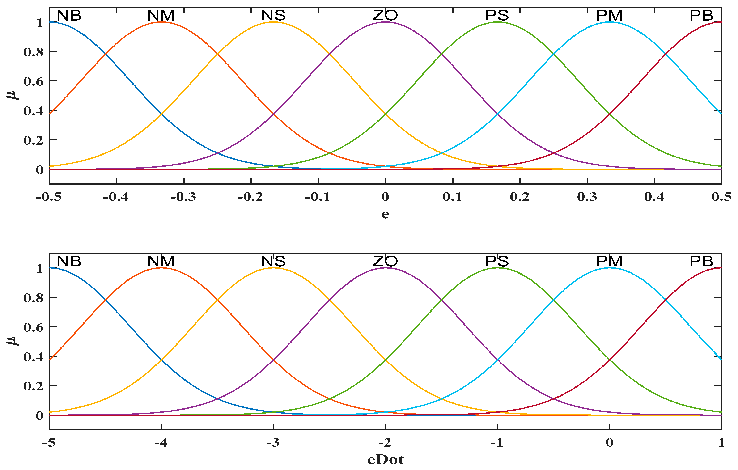
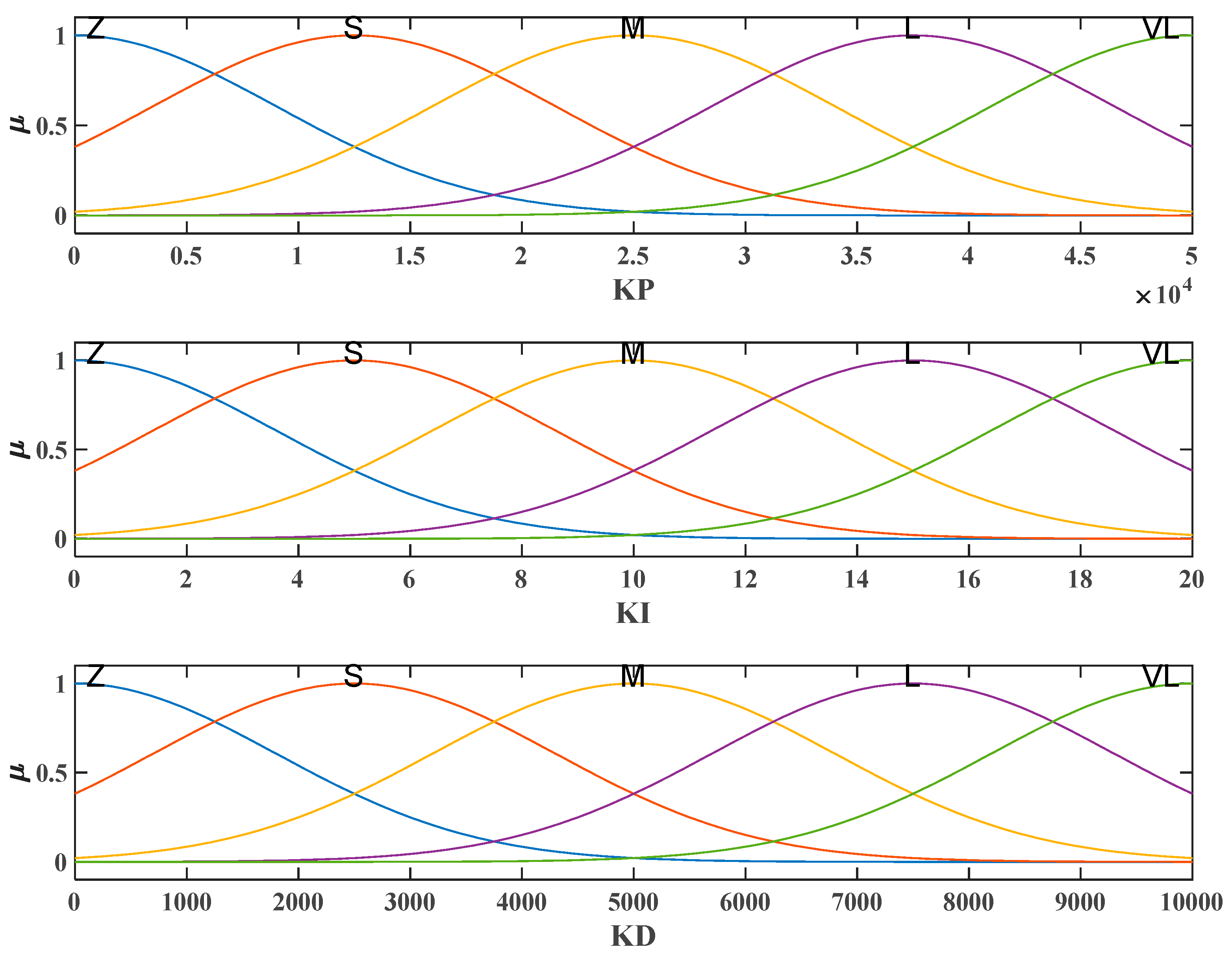
Development of a fuzzy inference system with Gaussian membership functions to tune PID gains online based on front-wheel angle tracking errors.
Design of an optimal observer-based Backstepping Controller for improving vehicle lateral stability and heading regulation.
Integration of the fuzzy PID inner loop and the GA-tuned BSC outer loop into a unified SBW control framework for robust performance under multiple disturbance sources.
Although the 2-DOF bicycle model is widely adopted for controller synthesis and analytical development due to its low complexity and clear physical interpretability, it does not explicitly capture some higher-order vehicle motions and couplings present in a more comprehensive full-vehicle representation. To address this limitation and to further examine the robustness of the proposed method, an additional 6-degree-of-freedom vehicle model is considered as a complementary validation framework. It should be emphasized that the bicycle model remains the principal model for control design and theoretical analysis, whereas the 6-DOF model is employed only to provide supplementary simulation-based validation.
The remainder of this paper is organized as follows.
Section 2 presents the equations of motion of the vehicle.
Section 3 describes the SBW dynamics.
Section 4 develops the nonlinear disturbance observer and analyzes the estimation error stability.
Section 5 introduces the fuzzy PID controller design.
Section 6 presents the Backstepping Controller design.
Section 7 discusses the simulation results. Finally, the conclusions are given in the last section.
2. Dynamics Laws and Equations
To design the proposed dual-loop controller, a control-oriented mathematical model is required for both the vehicle lateral motion and the steer-by-wire (SBW) actuation system. Since the main objective of this study is lateral position tracking and heading-angle regulation, a bicycle model is adopted for the vehicle dynamics. This reduced-order model captures the dominant lateral and yaw dynamics required for controller design with relatively low computational complexity, while maintaining sufficient physical interpretability for analysis and control synthesis. It is particularly appropriate under moderate driving conditions and small side-slip and steering angles, where higher-order effects such as roll, pitch, load transfer, and strongly nonlinear tire dynamics can be neglected. Therefore, the applicability of the proposed controller should be interpreted within these commonly accepted modeling assumptions. Compared with higher-order full-vehicle models reported in the literature [
29,
30], the bicycle model provides a suitable balance between modeling simplicity and control relevance. In addition, the SBW mechanism is modeled as a second-order actuator dynamic system relating the motor torque to the front-wheel steering angle. The combined model forms the basis for the controller and observer design developed in the subsequent sections.
2.1. Vehicle Lateral-Yaw Dynamics
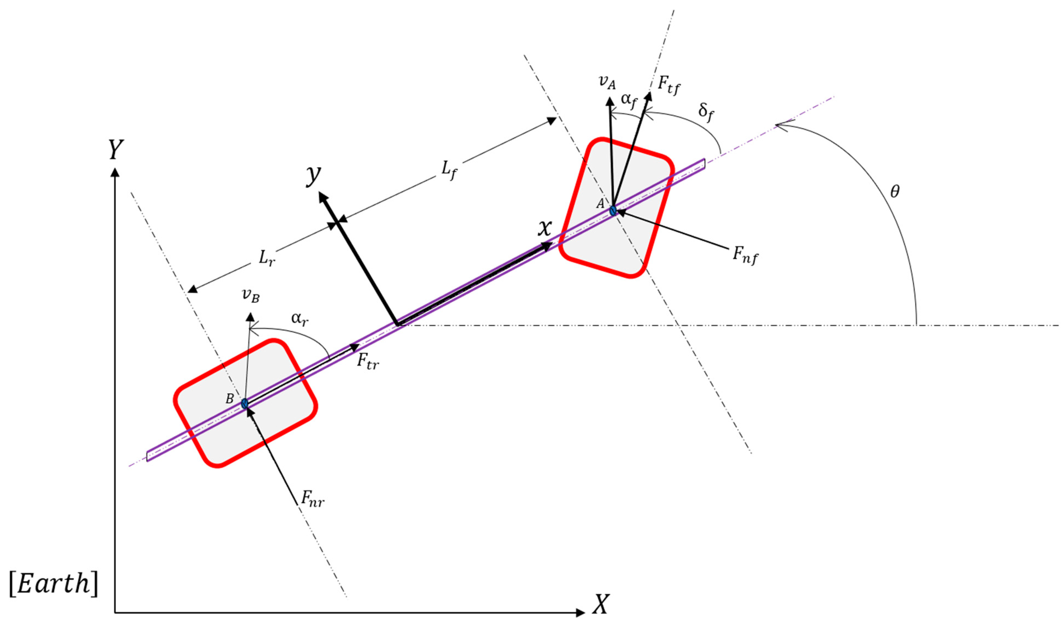
A schematic of the bicycle model and the associated coordinate frames is shown in
Figure 1. The following assumptions are adopted to derive the lateral-yaw motion equations:
The vehicle moves on a flat road surface, and tire-contact deformations are neglected.
Roll and pitch motions are ignored.
The longitudinal velocity is assumed constant.
Longitudinal aerodynamic drag is neglected, while lateral wind effects are represented as an external disturbance input.
Under these assumptions, the vehicle dynamics can be described using the well-known bicycle model. Let
and
denote the vehicle position in the inertial frame, and let
be the heading angle. By considering the lateral force balance and yaw-moment balance, one obtains
where
is the lateral acceleration of the center of mass. Assuming small tire slip angles for the front and rear wheels and neglecting tangential tire forces, the lateral and yaw dynamics are expressed as [
31,
32,
33]:
where
and
are the cornering stiffness coefficients of the front and rear tires, respectively;
and
denote the distances from the center of mass to the front and rear axles;
is the vehicle mass;
is the yaw moment of inertia;
is the longitudinal velocity;
is the lateral velocity; and
is the front-wheel steering angle.
The kinematic relations between the body-fixed frame and the inertial frame are:
For small steering and heading angles, these equations can be approximated by
Defining the state vector as
and taking the steering angle as the control input,
the control-oriented state-space representation of the vehicle dynamics in the presence of wind disturbance can be written as [
34,
35]
where
,
,
,
,
,
,
, and
represents the external wind disturbances, respectively. The state-space model in (10) forms the basis for the outer-loop control design developed in the following sections.
2.2. Steer-by-Wire Actuator Dynamics
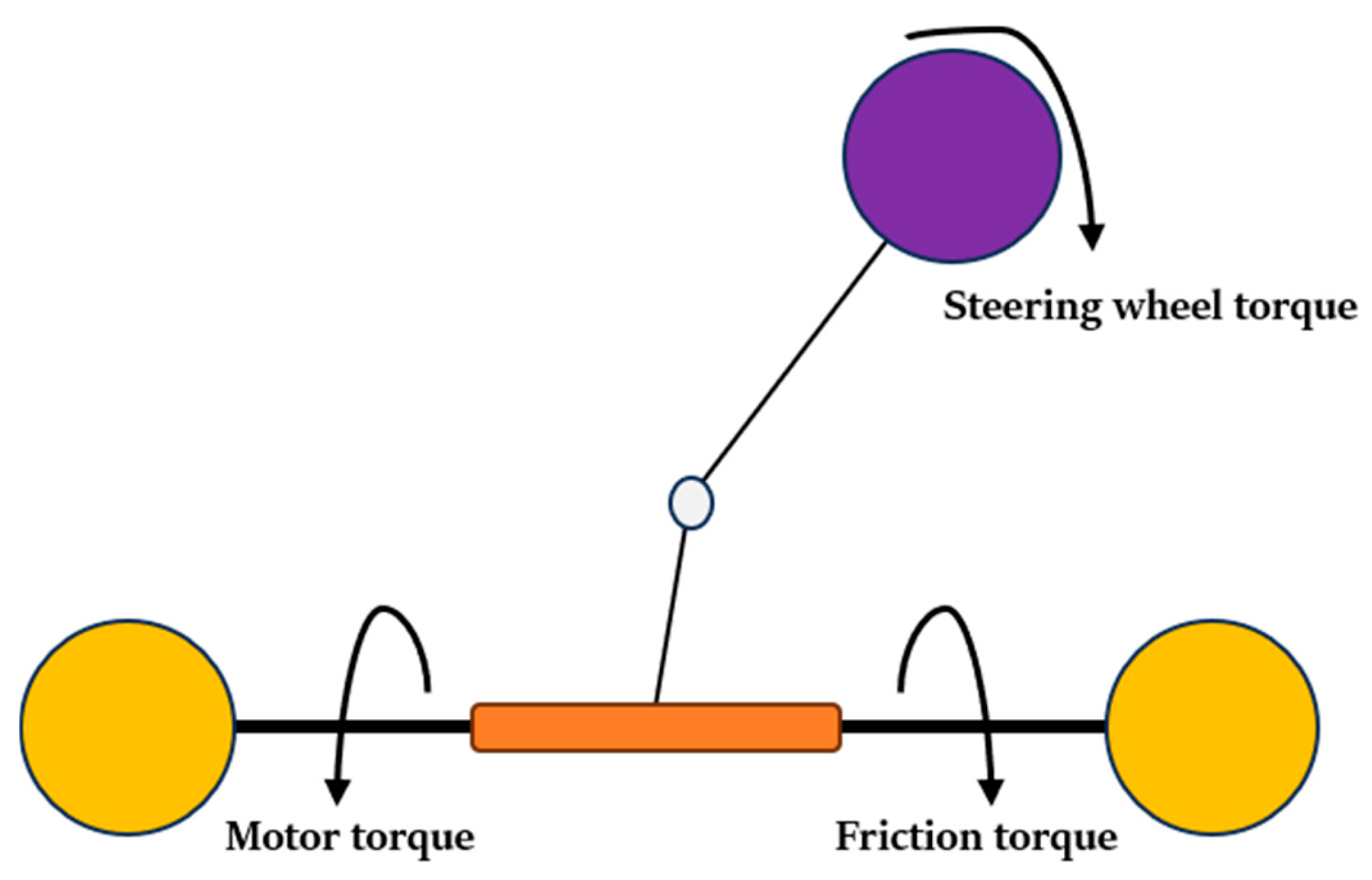
The physical structure of the SBW mechanism is illustrated in
Figure 2. In this subsystem, the motor torque acts as the control input and generates the front-wheel steering angle required by the vehicle dynamics. A second-order linear model is adopted to describe the relation between the applied torques and the steering angle [
36,
37]:
where
, and
are the effective inertia, damping, and stiffness of the whole SBW, respectively,
is the motor torque,
is the steering torque of the front wheel,
is the friction torque, and
denotes the road vibrations generally time-varying and unknown.
In this study, the steering torque and friction torque are neglected to obtain a simplified control-oriented model. This approximation is justified by the decoupled structure of the SBW mechanism and the relatively high bandwidth of the steering actuator. As a result, disregarding the aforementioned torques, the state space model of Equation (11) Accordingly, the state-space form of (11) can be written as
and the control signal
:
2.3. Integrated Model and Control Objective
The vehicle lateral-yaw dynamics and the steer-by-wire actuator dynamics constitute two interconnected subsystems in the proposed control framework. The outer-loop controller is designed based on the vehicle model to generate the desired front-wheel steering command required for lateral position and heading-angle tracking. The inner-loop controller is then employed to regulate the SBW actuator such that the actual steering angle follows the desired steering command. Therefore, the steering angle acts as the coupling variable between the vehicle dynamics and the SBW actuator dynamics.
In the vehicle subsystem, the front-wheel steering angle is considered as the control input that directly affects the lateral and yaw motions of the vehicle. In the SBW subsystem, the motor torque is regarded as the actuator input that generates the required steering angle. Accordingly, the overall control problem is formulated in a cascaded manner, where the outer loop determines the desired steering angle , and the inner loop ensures that the actual steering angle tracks despite actuator uncertainties and external disturbances.
The following assumption is considered for the external disturbances affecting the vehicle and SBW subsystems.
Assumption 1. The external disturbances associated with wind flow and road-induced vibrations are bounded by unknown positive constants, i.e.,where and are unknown positive constants. Based on the above modeling framework, the main objective of this study is to design a dual-loop control scheme such that the lateral position and heading angle track their desired reference trajectories in finite time. Simultaneously, the actual front-wheel steering angle is required to accurately follow the desired steering command , despite the presence of wind disturbance and road-induced disturbance . This formulation provides the basis for the controller and observer design presented in the following sections.
2.4. Complementary 6-DOF Vehicle Model for Validation
The main analytical developments of this study are derived based on the 2-DOF bicycle model introduced in the previous subsections. In order to assess the effectiveness of the proposed method under a more detailed dynamic description, a supplementary 6-DOF vehicle model is also considered for validation purposes. This extended model includes additional longitudinal, lateral, yaw, and wheel-related dynamics, thereby providing a richer representation of the vehicle motion. It is used exclusively in the simulation stage and does not replace the reduced-order model employed for controller synthesis and theoretical derivations.
3. The Design Procedures of the Finite-Time Estimator
A terminal finite-time disturbance observer is proposed in this section to estimate the wind disturbances applied to the lateral dynamics of the car. Employing the disturbance observer not only enhances the tracking performance but also alleviates the steering angle. According to Equation (10), the lateral dynamics may be described in compact form as:
where
,
,
, and
, respectively.
The terminal estimator is designed as follows [
38]:
where
,
and
are all positive coefficients;
and
are positive odd integers satisfying
. In relation to two auxiliary variables
and
, the disturbance estimation error may be calculated with the following calculation steps:
where
is defined such that:
Then, by taking the first time derivative of the variable
, we may write:
Theorem 1. Consider the state-space system in Equation (13) with , and suppose that the external disturbance is bounded according to Assumption 1. Let the nonlinear estimator of Equation (14) be designed with positive coefficients and positive odd integer exponents satisfying . Then, for any initial conditions in the admissible domain, the disturbance estimation error converges to zero in finite time; that is, there exists a finite uch that or all .
Proof. We employ the Lyapunov function as
. Then its first time derivative will be:
which shows the finite-time convergence of estimation errors. It should be noted that the upper bound of reaching time to the origin relies on the design parameters of the estimator. □
Remark 1. To show the bounded settling time, one may integrate inequality (18) as: Hence, the settling time of error dynamics is bounded, and the estimation error trajectories converge to the origin in a finite time.
5. Optimal Backstepping Outer-Loop Control
The outer-loop controller is designed to generate the front-wheel steering reference required for lateral trajectory tracking. Its objective is to force the vehicle to follow a prescribed lateral path within finite time while ensuring closed-loop stability.
Based on the vehicle lateral dynamics, the tracking errors are first defined and then incorporated into a backstepping design framework. A virtual control law is introduced for the intermediate subsystem, after which a Lyapunov-based recursive design is applied to derive the final steering-reference command. This procedure leads to the control law given in Equation (20), which serves as the reference input to the inner-loop steering controller.
The stability of the resulting closed-loop system is established through Lyapunov analysis. As stated in Theorem 1, when the control law in Equation (20) is applied to the lateral vehicle model, the tracking errors asymptotically converge to zero and the closed-loop system is globally asymptotically stable.
To improve controller performance, the backstepping parameters and are optimized offline using a genetic algorithm (GA) by minimizing the cost function. The MATLAB R2025b built-in ga function is employed for this optimization, with the generation size and crossover coefficient set as reported in the manuscript. The optimal parameters obtained offline are then used in the outer-loop controller during simulation.
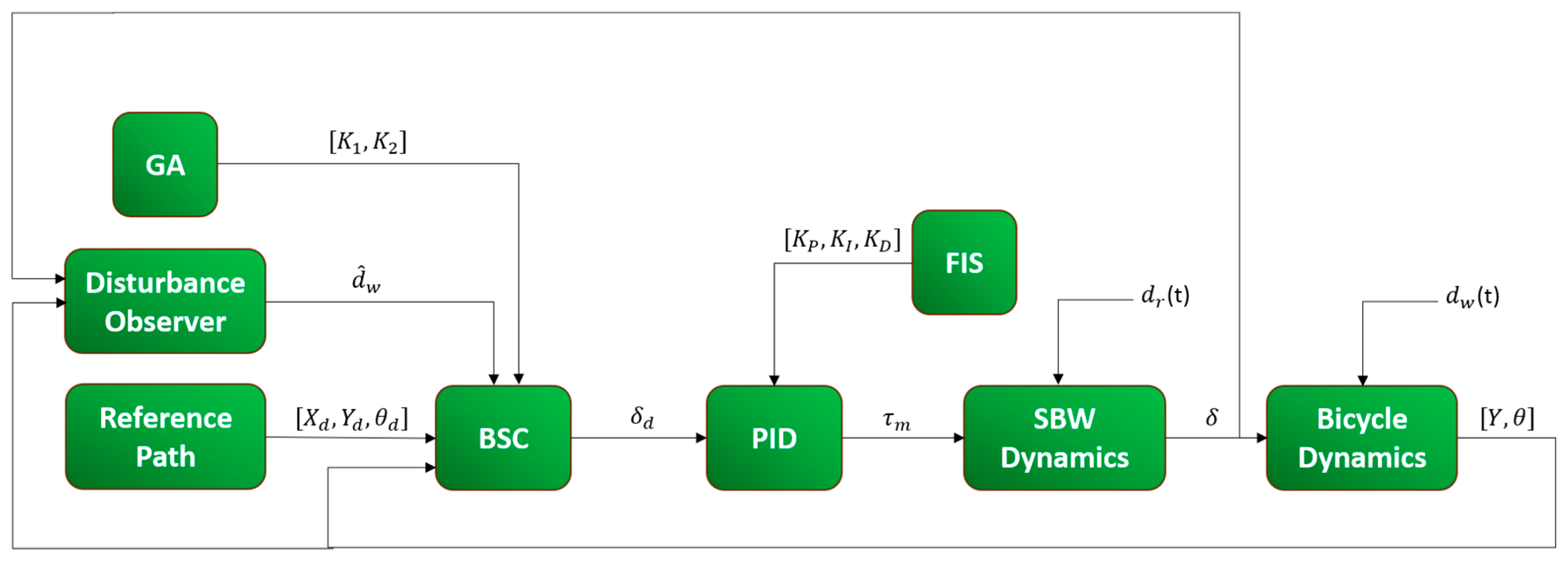
The complete dual-loop structure is depicted in
Figure 5, where the outer-loop BSC generates the steering reference for path tracking, the inner-loop fuzzy PID tracks this reference, and the overall architecture combines offline GA tuning with online fuzzy adaptation.
6. Simulation Results
6.1. Simulation Results Based on the 2-DOF Bicycle Model
In this section, the simulation results of the designed control scheme are presented to demonstrate the effectiveness of the proposed dual-loop controller applied to the vehicle dynamics and the SBW system. The main objective of this section is to assess the capability of the proposed control framework in terms of trajectory tracking, steering performance, disturbance estimation, and robustness in the presence of external perturbations. The physical characteristics of the considered system used in the simulations are [
40]:
,
,
,
,
,
,
,
, respectively.
The simulations were conducted in a discrete-time framework with a fixed sampling interval of 0.001 s (1000 Hz) over a duration of 10 s. This sampling rate was selected to be sufficiently high relative to the dominant steer-by-wire actuator and vehicle lateral-yaw dynamics, so that the sampled-data implementation closely reproduces the continuous-time closed-loop response. At each sampling instant, the system states, observer variables, and control inputs were updated sequentially. For performance evaluation, the vehicle was commanded to follow a double-lane-change (DLC) maneuver, and the reference heading angle was generated from the desired trajectory as . This maneuver was adopted because it provides a representative and sufficiently challenging benchmark for assessing both lateral tracking accuracy and vehicle stability.
The mentioned wind flow for the vehicle and the road vibrations for the SBW were modeled as bounded sinusoidal signals, whose mathematical expressions are given in Equations (21) and (22):
The inclusion of these disturbance signals allows the robustness of the proposed controller and observer to be examined under realistic uncertain operating conditions.
The weighting constant of the performance index in the GA was considered equal to 10, and the optimization results obtained by the GA and used in the simulations for the BSC are
, and
In addition, the disturbance observer parameters used in the estimation formulation are listed in
Table 4. Furthermore, in order to eliminate the chattering inherent in the sliding surface of the disturbance observer, the sign function was replaced by the tanh function in the simulation studies.
According to
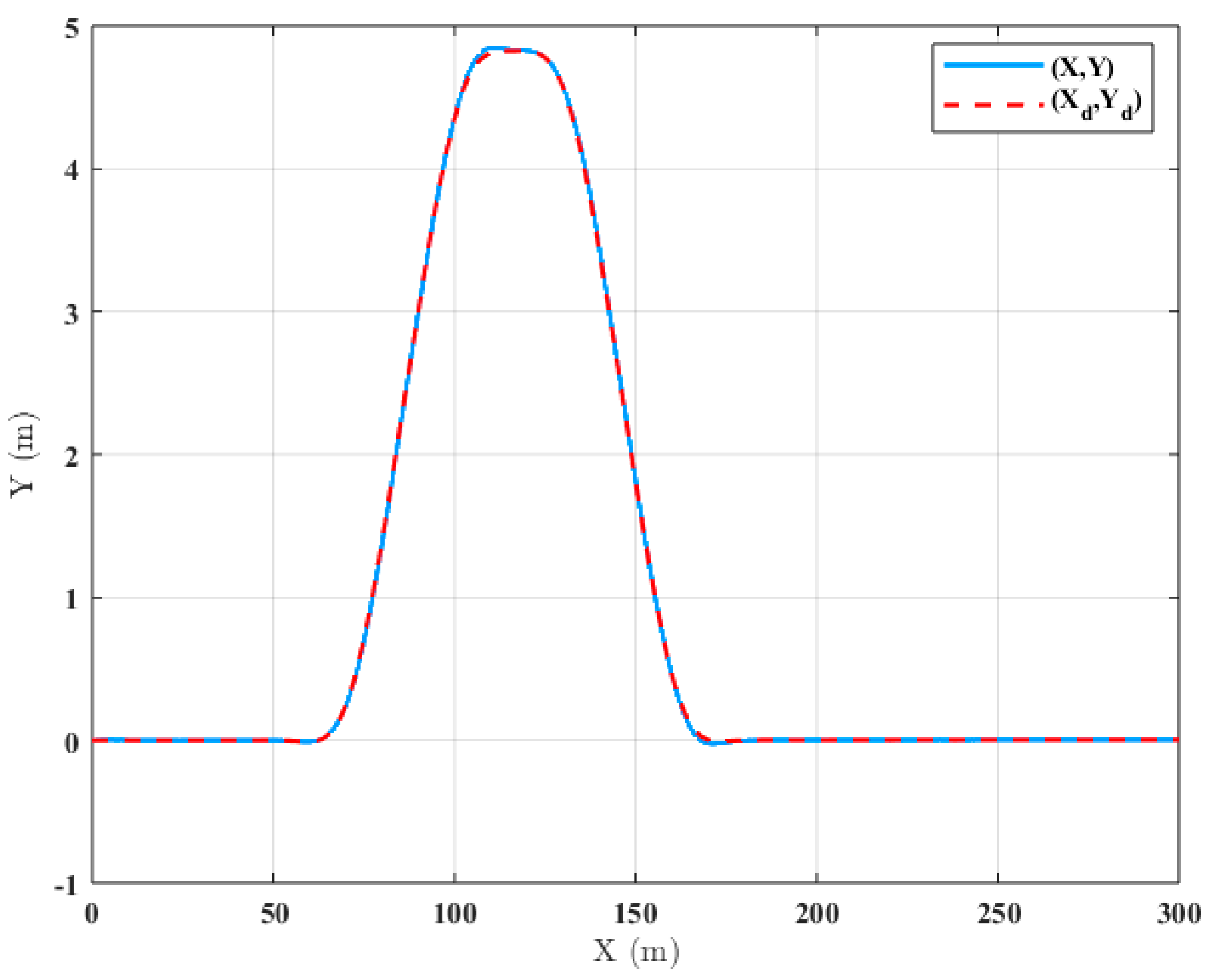
Figure 6, the proposed control unit precisely navigates the vehicle through the prescribed trajectory in the phase plane. It can be seen that the settling time is finite and that the trajectory following of the X and Y positions has taken place with remarkable accuracy even in the presence of external disturbances. This result confirms the effectiveness of the proposed outer-loop controller in preserving accurate path-following performance despite the existence of disturbance inputs.
Figure 7 illustrates the heading angle of the vehicle. It can be seen that while no actuation signal directly controls the vehicle heading angle, the output response is acceptable in both transient and steady-state behaviors. This observation indicates that the overall control structure is able to regulate the heading response indirectly through the coordinated action of the steering and lateral dynamics.
The tracking error trajectories are shown in
Figure 8. It is obvious that the steering angle obtained by the fuzzy PID control unit has managed to make the steady-state error zero for the lateral movement. However, due to external disturbances and the lack of an actuation signal for the heading angle, its steady-state error is not zero, although it remains bounded. Overall, the closed-loop system is stable and the tracking errors have converged to zero in a finite time. Therefore, the simulation results verify that the proposed control strategy ensures satisfactory lateral tracking performance while preserving bounded heading error under disturbed conditions.
Figure 9 presents the steering angle of the front wheel. In relation to
Figure 8, the steering angle has followed the reference command with excellent accuracy. The output behavior depends significantly on both the outer- and inner-loop control performances. The reference command has been generated via the outer control, and the inner control has utilized the reference signal to minimize the deviations between these two values. As a result, the outer controller is responsible for the correction of the front-wheel steering to enhance the stability of the vehicle. This demonstrates the effectiveness of the hierarchical dual-loop architecture in coordinating the trajectory-generation and steering-actuation tasks.
According to
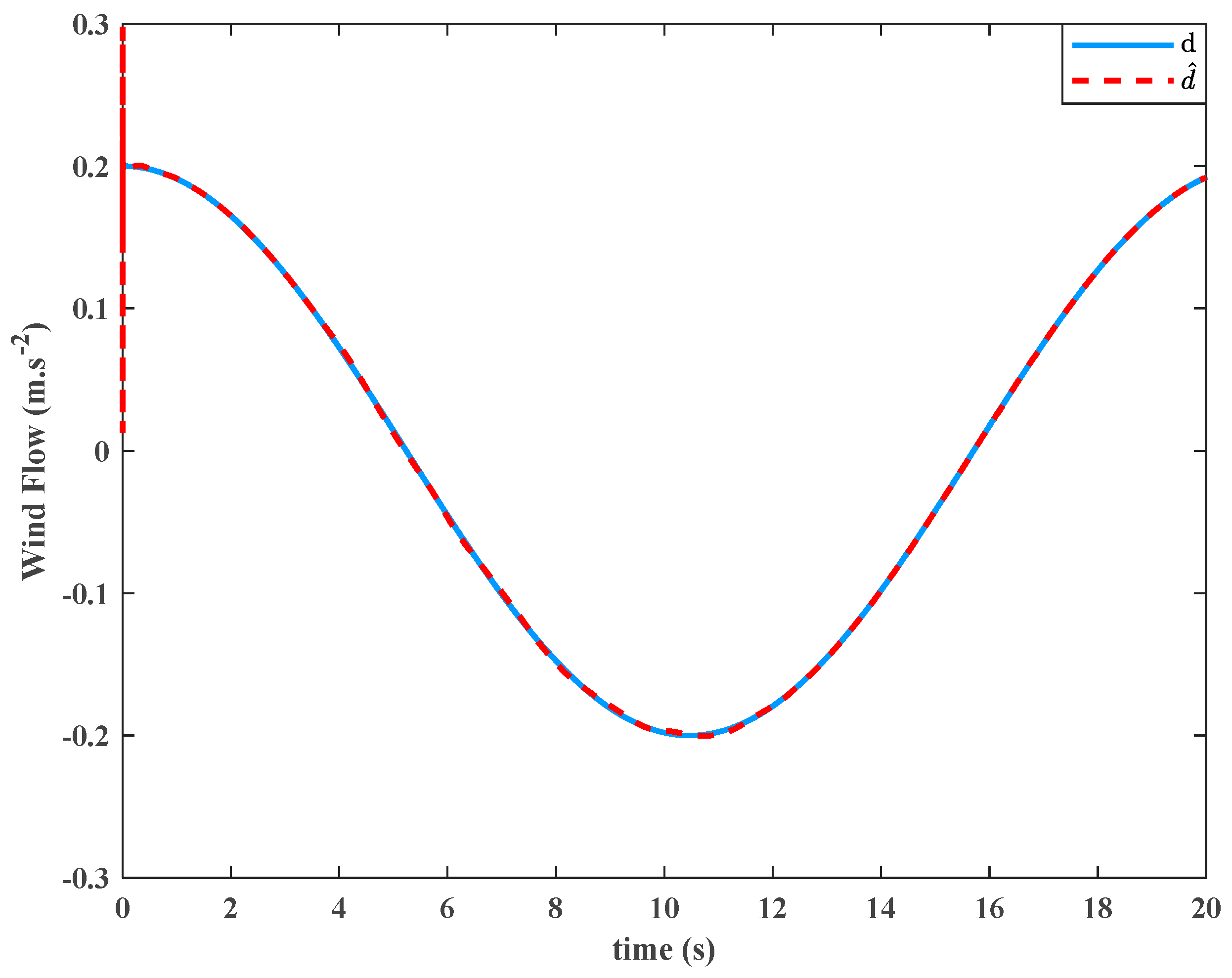
Figure 10, the external wind disturbances have been estimated with significant accuracy within a finite time. The output behavior reveals a significant initial overshoot in the estimated disturbance signal. Regarding this transient anomaly, the estimation algorithm demonstrated robust performance, achieving rapid convergence to the true disturbance profile within a short time. Hence, despite the transient overshoot, the observer provides a sufficiently accurate and fast disturbance reconstruction process.
Accordingly,
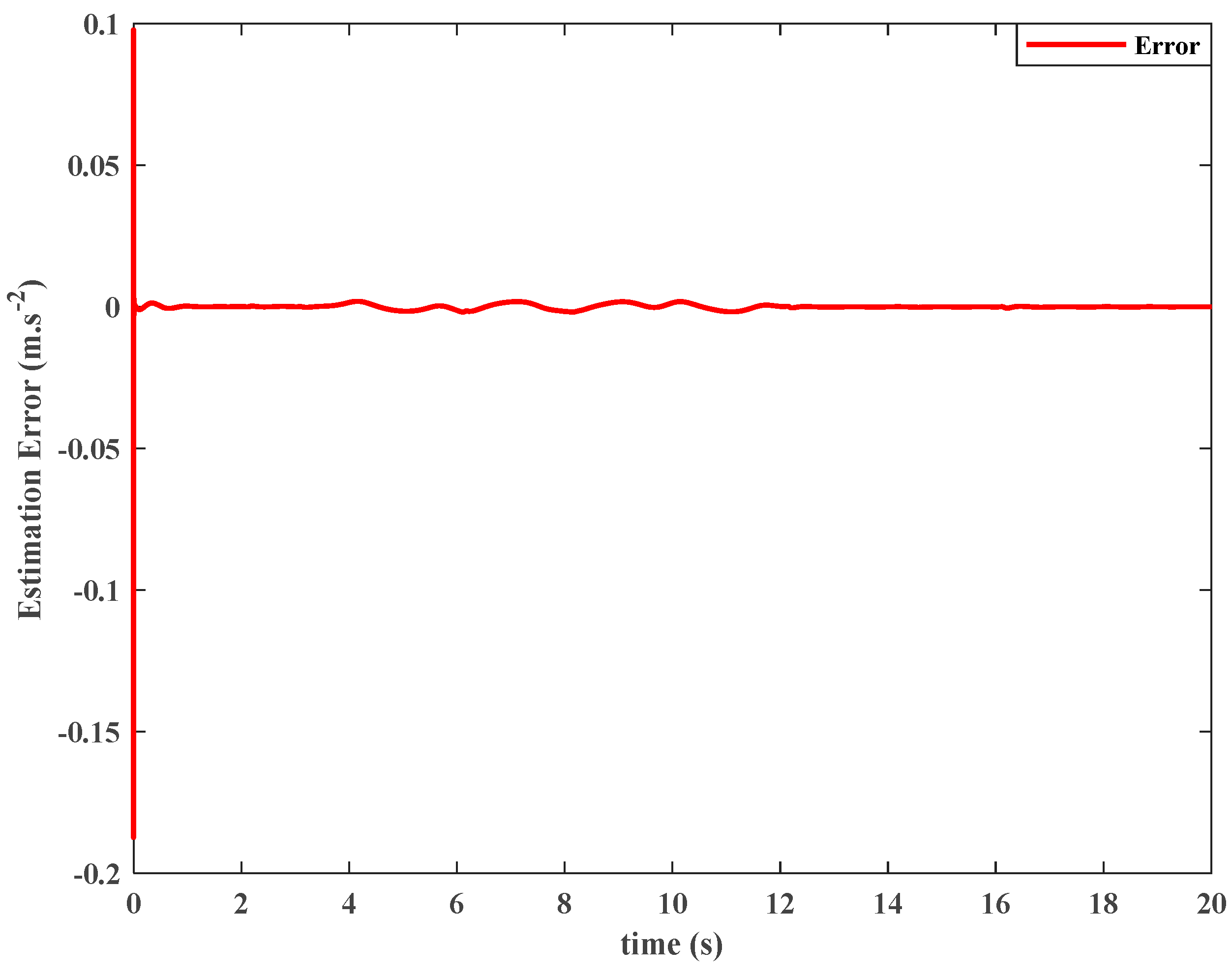
Figure 11 illustrates the estimation error behavior. The most critical result understood from the figure is that the error signal demonstrates finite-time convergence to zero, which was proved via the Lyapunov theorem. Furthermore, it can be observed that with a correct choice of observer gains, a remarkably short settling time is achieved. This behavior conclusively validates the efficacy of the proposed observation technique. The rapid and exact convergence to zero ensures that any downstream disturbance rejection control law can perfectly cancel the estimated disturbance, leading to robust overall system performance. This result further confirms the practical usefulness of the observer in enhancing disturbance attenuation and improving the robustness of the closed-loop control system.
The online convergence of PID gains to their final values is shown in
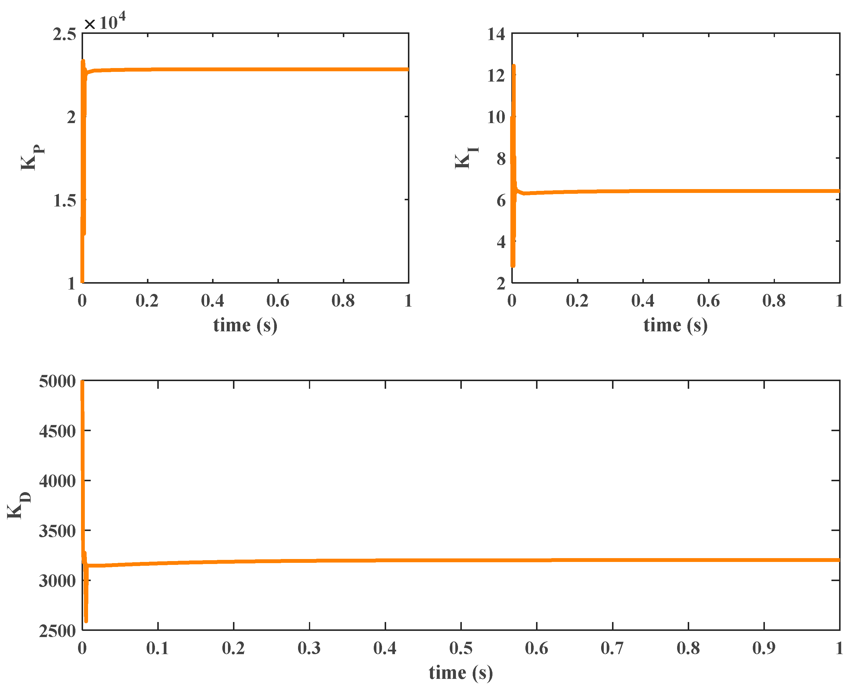
Figure 12. It can be observed that due to large errors in the transient response of the closed-loop control scheme, the initial gains are of high values. The FIS adaptively adjusts the gains so that the error signal and its corresponding time derivative are minimized and the best performance of the SBW system is guaranteed. However, in the steady-state conditions, the gains have converged quickly to a constant value. This adaptive mechanism highlights the advantage of the fuzzy PID controller over fixed-gain controllers, since it improves transient performance while maintaining acceptable steady-state behavior. The results of the closed-loop algorithm confirm the efficiency of both inner fuzzy PID and observer-based optimal BSC in achieving the goal of trajectory tracking and stabilization of vehicle dynamics.
Overall, the obtained simulation results demonstrate that the proposed control framework provides accurate tracking, effective steering regulation, reliable disturbance estimation, and strong robustness against external disturbances, which supports its applicability to autonomous vehicle systems equipped with SBW technology.
6.2. Supplementary Validation Results Using the 6-DOF Vehicle Model
To further assess the effectiveness of the proposed method under a more comprehensive dynamic representation, supplementary simulations were performed using the 6-DOF vehicle model. The controller itself was still developed based on the 2-DOF bicycle model, and the purpose of this subsection is to verify whether the obtained tracking and control performance remains satisfactory in the presence of the additional vehicle dynamics. The results presented in
Figure 13,
Figure 14,
Figure 15,
Figure 16 and
Figure 17 indicate that the proposed approach preserves accurate path-following capability, acceptable heading regulation, and bounded steering effort under the extended validation model.
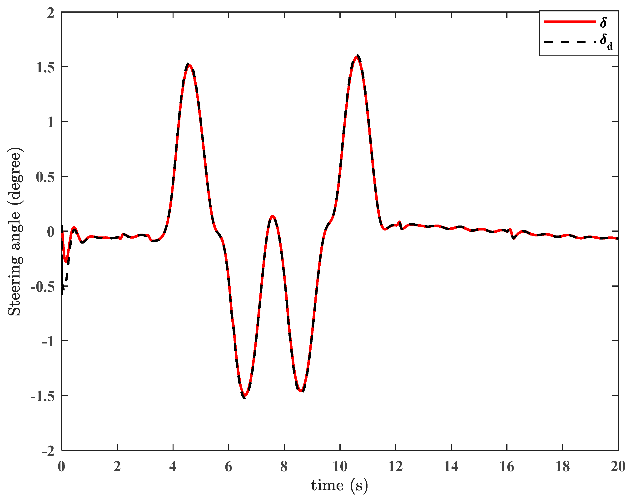
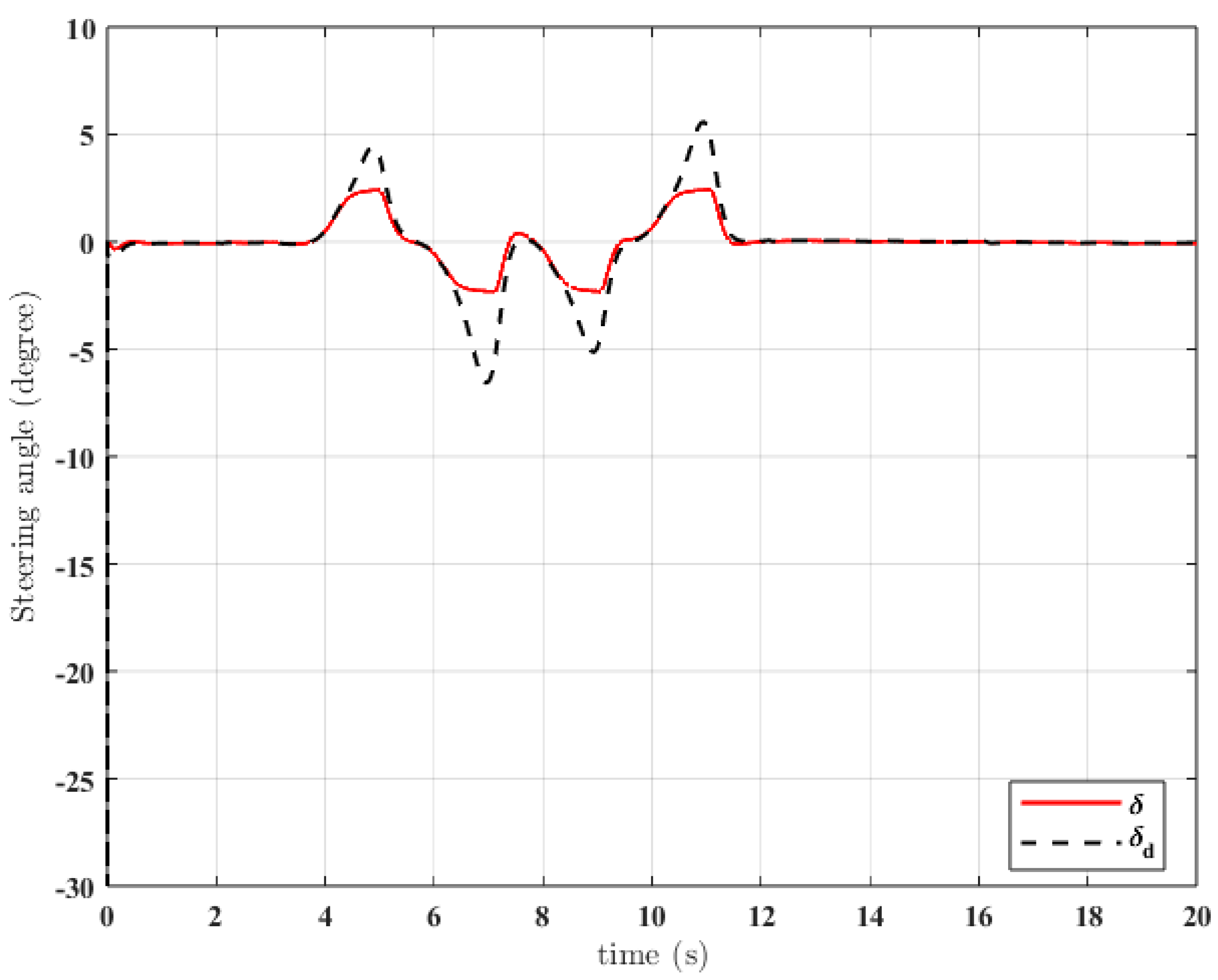
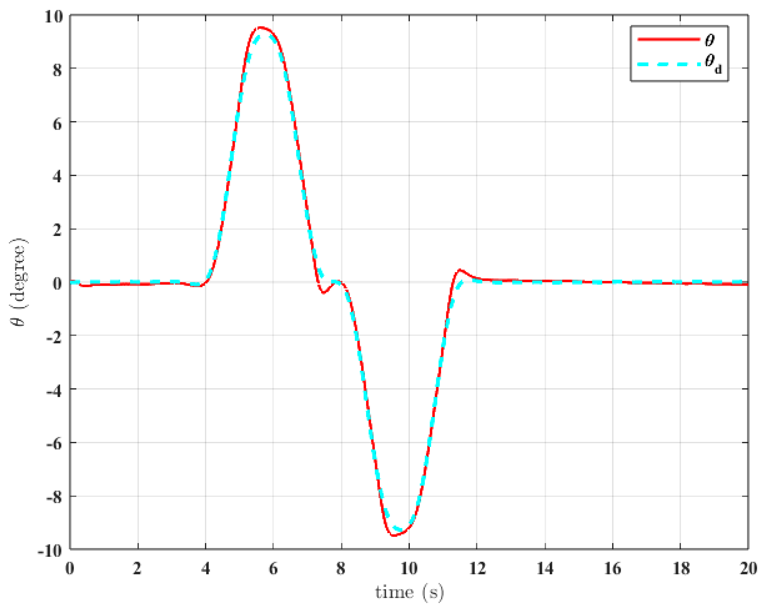
Figure 13 illustrates the steering response generated by the proposed controller together with the desired steering profile under the 6-DOF vehicle model. It can be observed that the actual steering angle follows the desired command with an overall smooth and bounded behavior. Although some attenuation appears around the peaks of the desired signal, the controller does not exhibit excessive oscillation or abrupt variations. This result indicates that the proposed control law remains practically realizable under the extended dynamics and does not require unrealistic steering effort to maintain the desired vehicle motion.
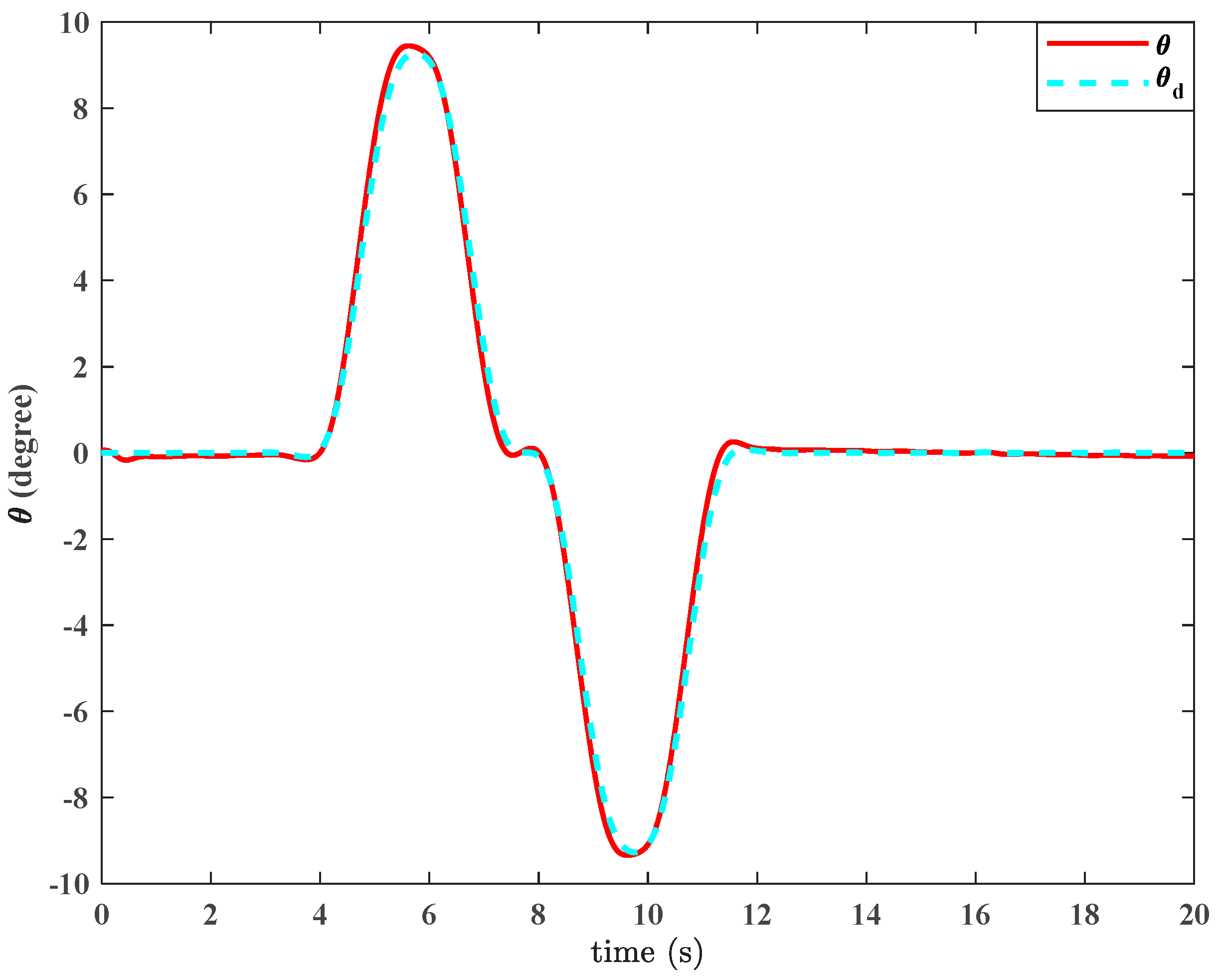
Figure 14 shows the time response of the vehicle orientation angle and its reference under the 6-DOF validation model. The actual response closely tracks the desired profile over the entire maneuver, with only very small deviations during the transient intervals. The absence of sustained oscillation and the fast recovery after the turning phases confirm that the proposed method provides accurate heading regulation even when the vehicle dynamics are represented by a higher-order model. Therefore, the consistency between the actual and desired orientation responses further supports the robustness of the control strategy.
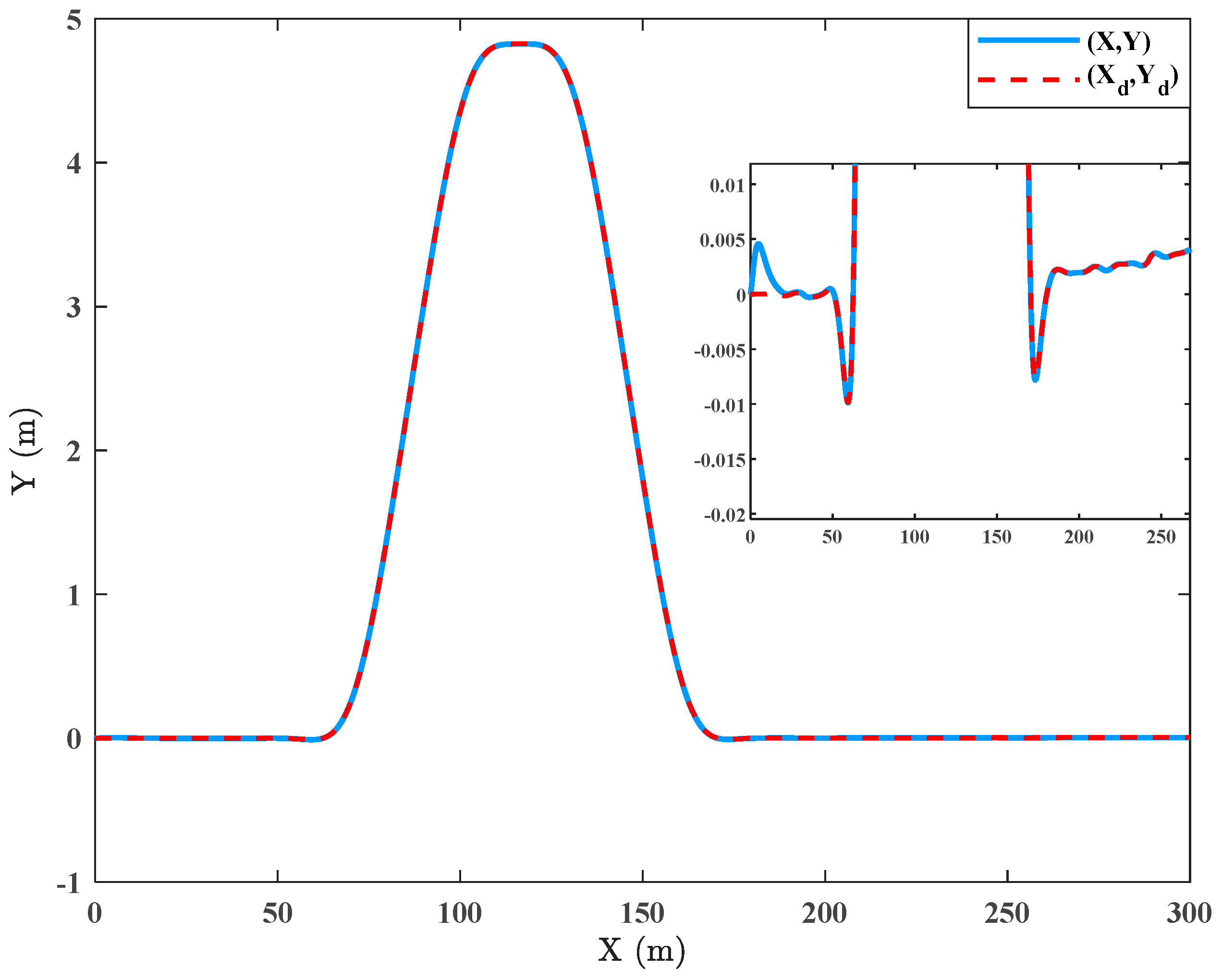
Figure 15 presents the vehicle trajectory in the
-
plane together with the desired path for the 6-DOF simulation case. As seen, the actual trajectory almost completely overlaps the reference path throughout the lane-change maneuver, indicating excellent lateral path-tracking performance. The small deviation observed during the transient portions remains limited and quickly vanishes after the maneuver. This close agreement demonstrates that the proposed controller, although designed using the reduced-order 2-DOF bicycle model, remains highly effective when evaluated in the more detailed 6-DOF vehicle environment.
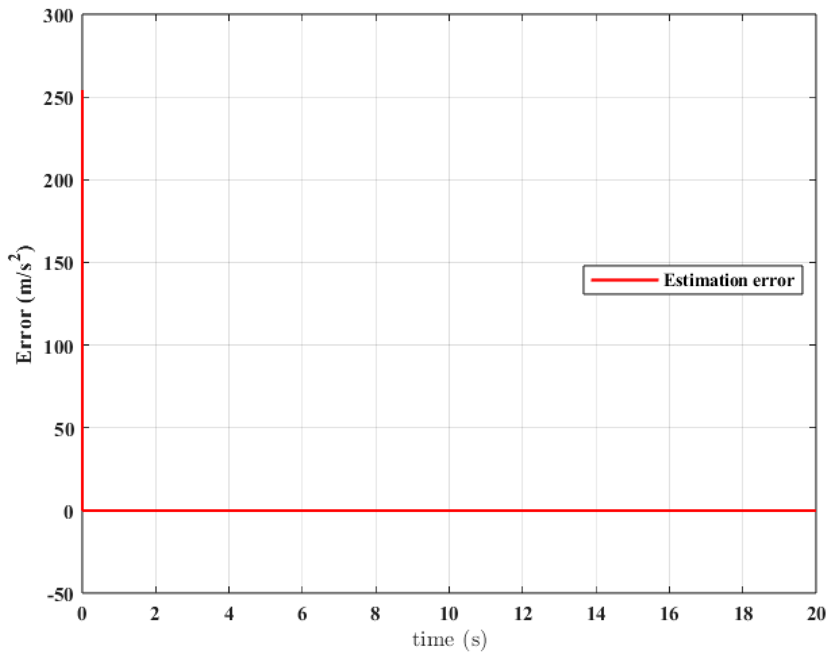
Figure 16 depicts the estimation error associated with the disturbance/uncertainty reconstruction mechanism under the 6-DOF model. A pronounced initial transient is observed at the beginning of the simulation, which can be attributed to initialization mismatch and the rapid adjustment of the estimator states. However, after this short transient interval, the estimation error quickly converges to a very small value and remains close to zero for the rest of the simulation. This behavior indicates that the estimation mechanism is able to recover rapidly and provide accurate steady-state estimation despite the presence of the additional dynamics in the 6-DOF model.
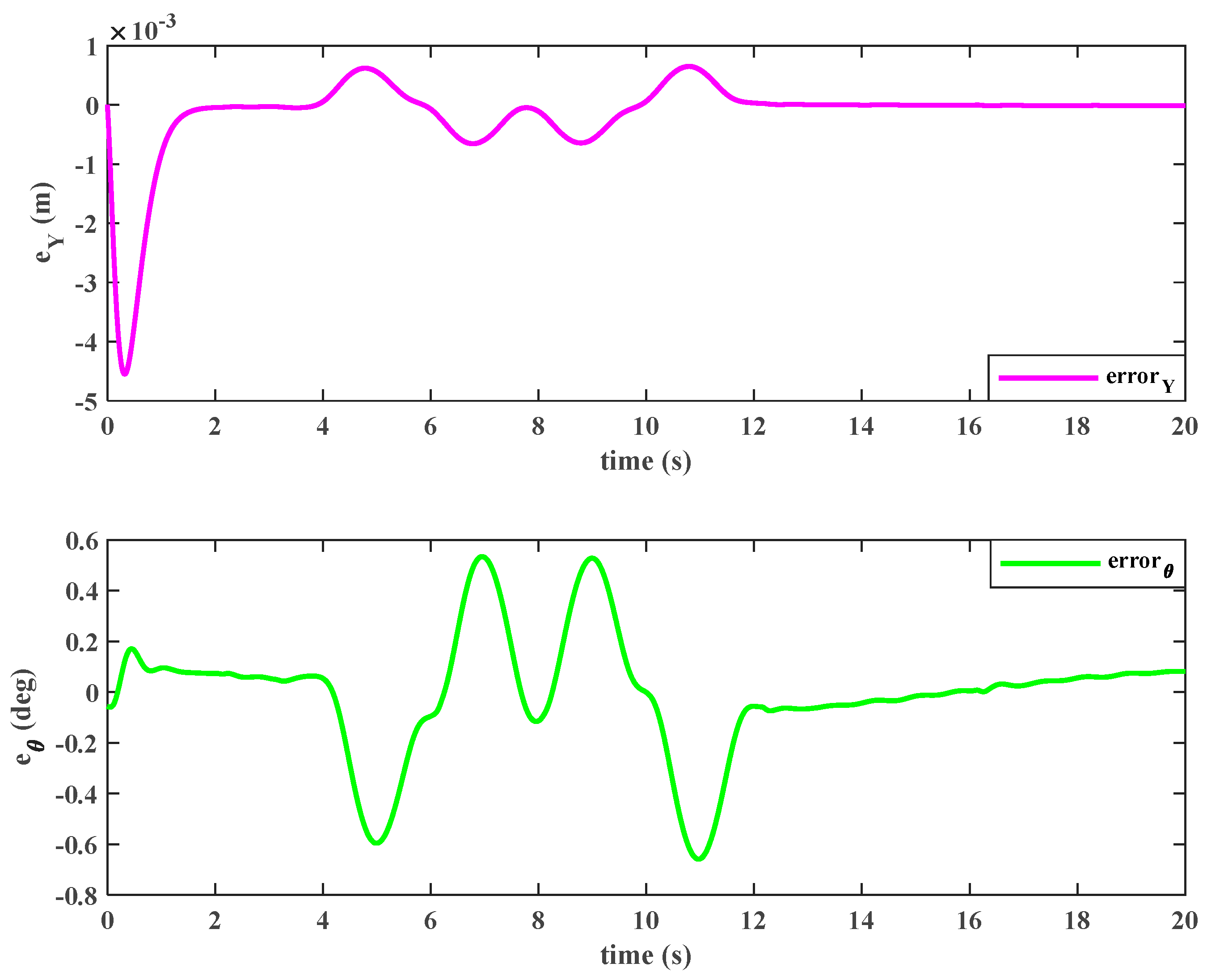
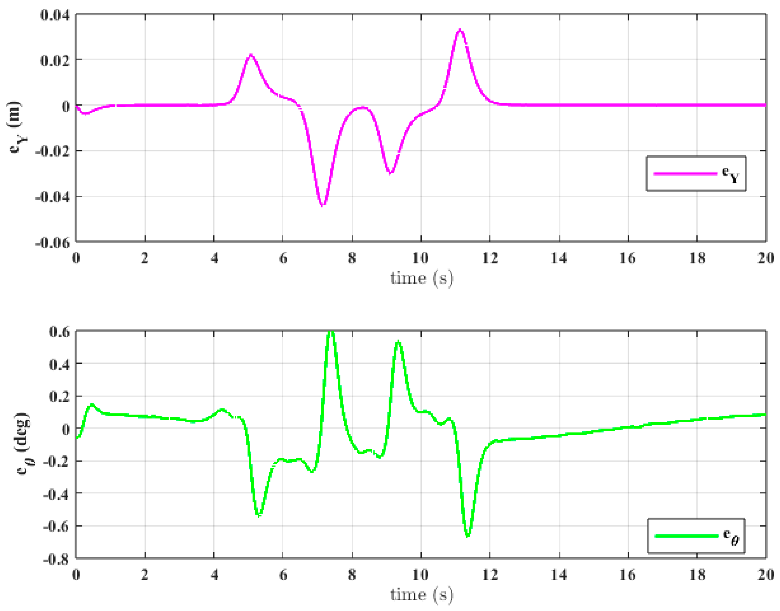
Figure 17 shows the lateral displacement error
and the orientation error
under the 6-DOF validation model. The lateral tracking error remains very small throughout the maneuver, with only limited transient peaks during the most demanding steering intervals. Similarly, the orientation error stays within a narrow range and does not exhibit divergent or persistent oscillatory behavior. These results confirm that the proposed approach preserves satisfactory tracking accuracy even when the simplified design model is replaced by a higher-order vehicle representation in simulation.
Overall, the 6-DOF simulation results confirm that the proposed method maintains the main performance characteristics already observed with the 2-DOF bicycle model. In particular, accurate path tracking, close orientation-angle tracking, and bounded steering effort are preserved, while the tracking errors remain small and well controlled. These observations indicate that the proposed controller is not overly dependent on the reduced-order design model and retains its effectiveness under a more comprehensive vehicle dynamics description.
6.3. Robustness Against Measurement Noise
To further investigate the robustness of the proposed controller, additional simulations were carried out under different levels of measurement noise. In this test, Gaussian noise was added to the measured states, while the actual system dynamics evolved using the true states. Hence, the control action was generated based on noisy measurements.
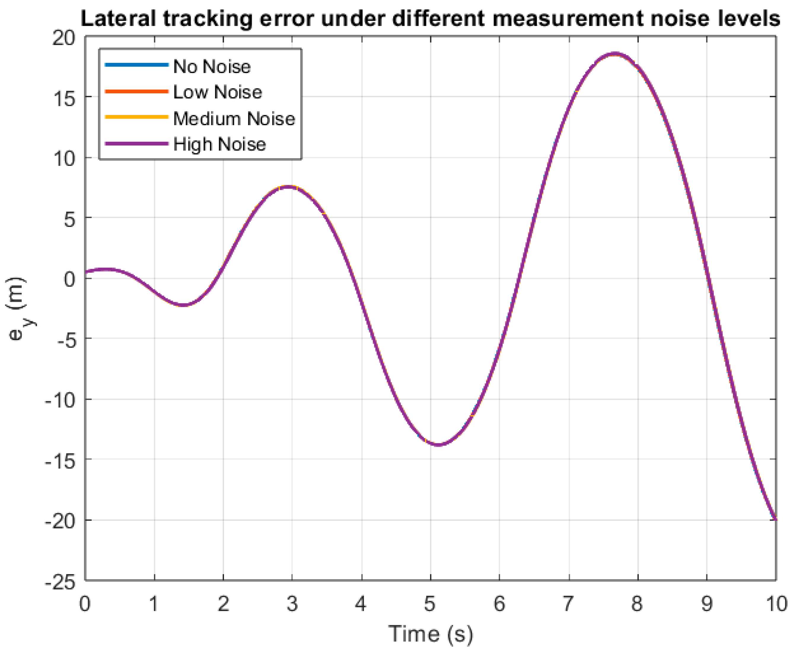
Figure 18 shows the lateral tracking error
under different measurement noise levels. It is clear that the responses for all noise scenarios are almost identical, indicating that the controller maintains accurate lateral tracking despite measurement corruption.
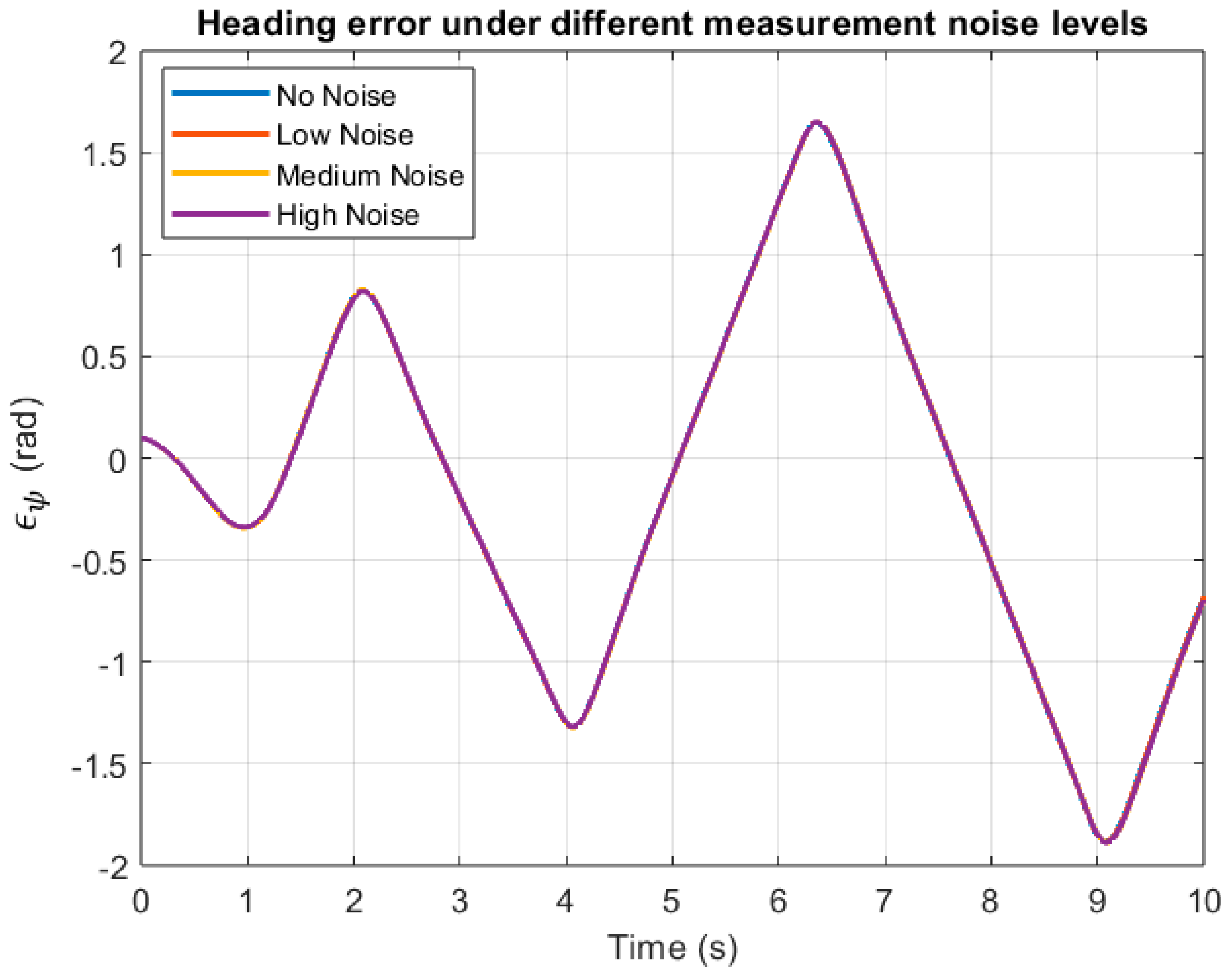
Figure 19 depicts the heading error
for the same cases. The curves remain nearly overlapping, which demonstrates that the yaw-related tracking performance is also highly robust to measurement noise.
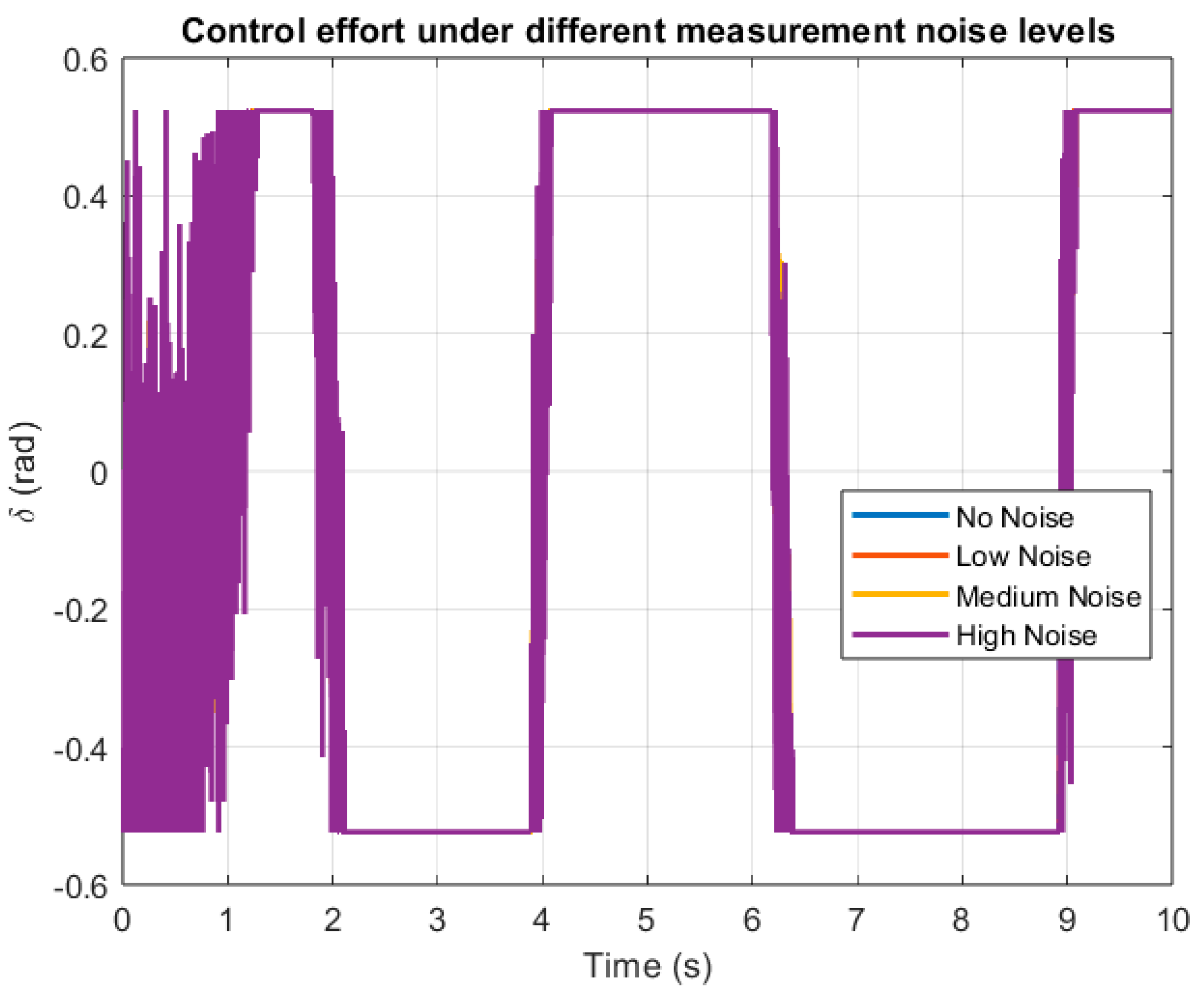
The control effort is shown in
Figure 20. Although the high-noise case introduces slight fluctuations during the transient phase, the control input remains bounded and stable in all scenarios. Therefore, the proposed controller preserves both performance and stability under noisy measurements.
6.4. Robustness Analysis Under Lateral Disturbance
An extensive robustness analysis was conducted in which a bounded lateral disturbance force was injected into the bicycle model. The disturbance amplitude was incrementally increased from 0 N to 10,000 N in steps of 100 N.
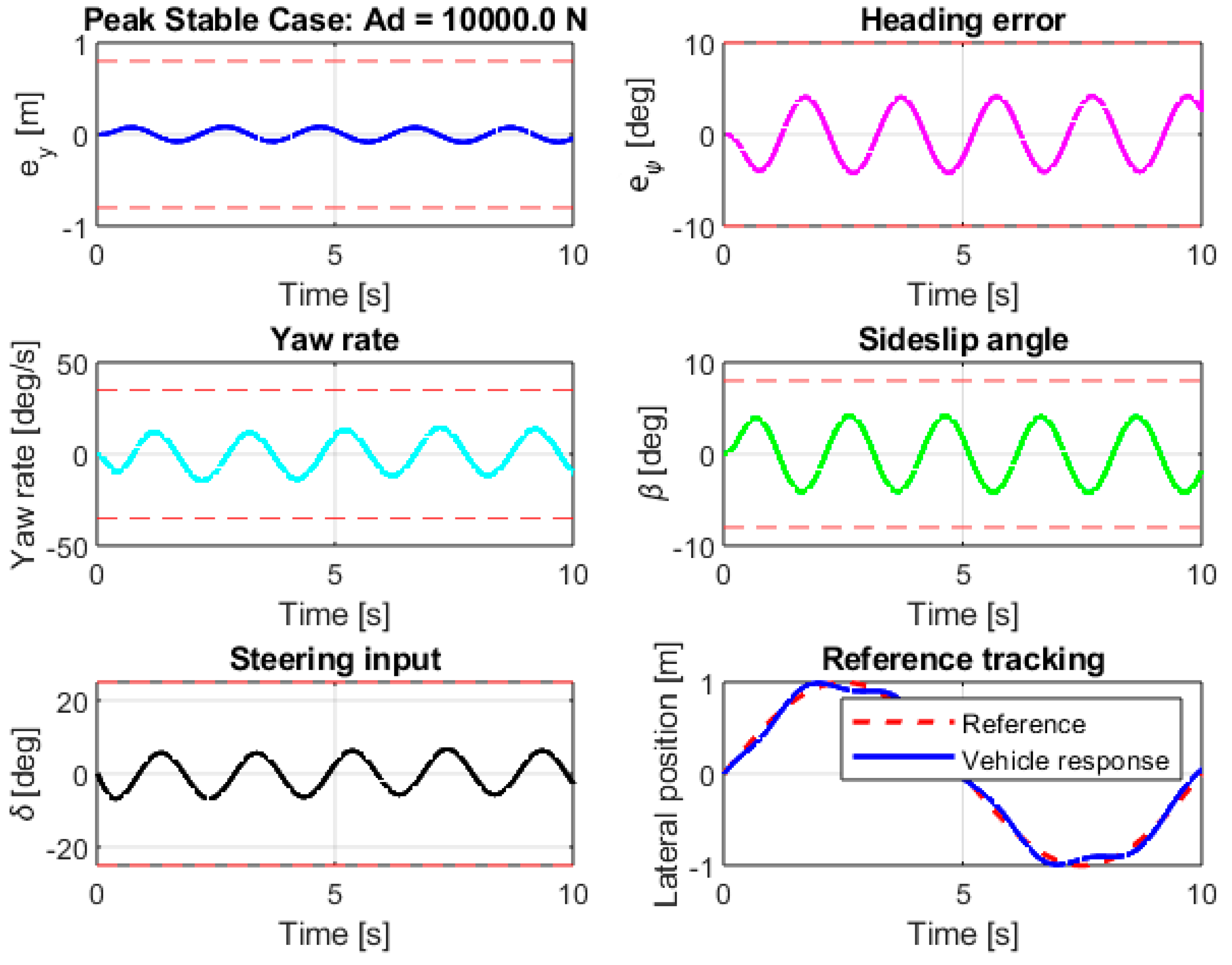
For each disturbance level, the closed-loop response was checked against the prescribed safety constraints, including limits on lateral error (|eᵧ| ≤ 0.8 m), heading error (|| ≤ 10°), yaw rate (|r| ≤ 35°/s), sideslip angle (|β| ≤ 8°), and steering angle (|δ| ≤ 25°). A simulation run was considered safe only if all constraints were satisfied throughout the entire maneuver.
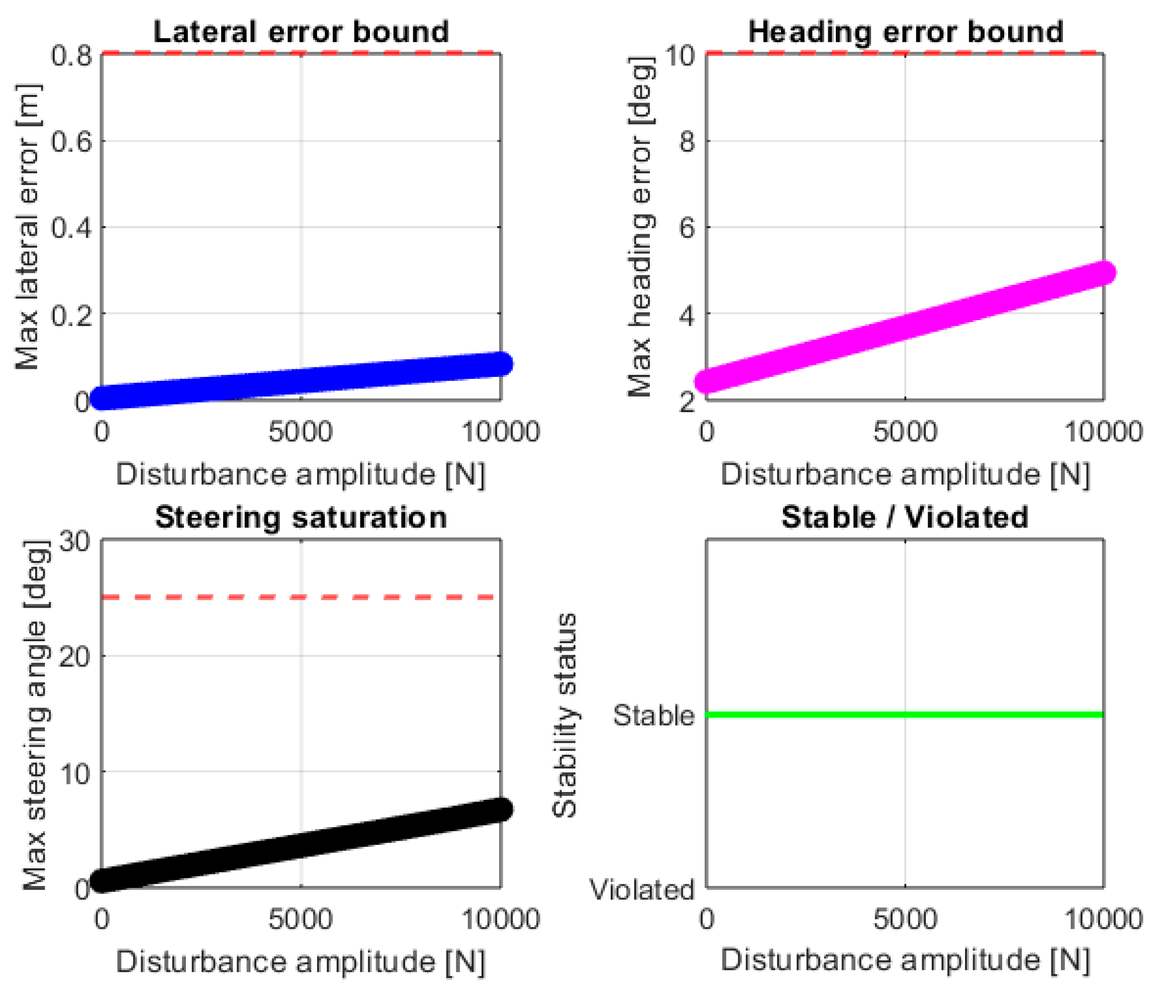
The obtained results (see
Figure 21) show that the proposed controller remained stable for all tested disturbance amplitudes up to 10,000 N. As the disturbance increased, the peak lateral error, heading error, yaw rate, sideslip angle, and steering input increased gradually but remained significantly below their admissible bounds. For the highest tested disturbance (10,000 N), the peak lateral error was 0.084 m, the peak heading error was 4.95°, and the maximum steering demand was 6.75°, all comfortably within their limits.
Representative time-domain responses for the worst tested case (
= 10,000 N) are shown in
Figure 21, confirming stable and well-damped behavior. The summary plots in
Figure 22 clearly indicate a monotonic increase in all metrics with disturbance amplitude, while no constraint violation occurred in the entire 0–10,000 N range.
These results demonstrate that, under the considered scenario, the proposed controller can tolerate a lateral disturbance force of at least 10,000 N without violating any safety constraints.
7. Conclusions
In this study, a robust dual-loop control strategy for autonomous vehicles with an SBW system was proposed, combining a Fuzzy PID controller for inner-loop torque regulation in SBW and a BSC integrated with a finite-time disturbance observer for outer-loop trajectory tracking and disturbance estimation. The proposed hierarchical control structure was designed to simultaneously address the steering actuator dynamics and the vehicle-level trajectory tracking problem under unknown time-varying disturbances.
Tuning the control parameters with an FIS and the GA guaranteed smaller overshoots and control efforts. The simulation results confirmed the effectiveness of the framework in achieving accurate lateral path tracking, fast settling time, and reliable disturbance rejection under unknown time-varying conditions. In particular, the obtained results demonstrated that the proposed controller can provide accurate trajectory tracking, bounded heading-angle response, finite-time convergence of tracking and estimation errors, and effective compensation of external disturbances such as wind flow and road-induced vibrations. Moreover, the adaptive adjustment of the PID gains through the FIS improved the transient response of the SBW system, while the GA-based optimization contributed to reducing the control effort and enhancing the overall closed-loop performance.
In addition to the main results obtained from the 2-DOF bicycle-model-based framework, supplementary simulations using a 6-DOF vehicle model were conducted to provide a more comprehensive validation of the proposed approach. The corresponding results confirmed that the main conclusions of the study remain valid under the extended dynamic representation. Therefore, while the reduced-order model remains the core framework for analysis and controller development, the additional full-vehicle simulations further support the effectiveness and applicability of the proposed method.
Despite these promising results, the present study has some limitations that should be explicitly acknowledged. First, the vehicle model was developed under several simplifying assumptions, including motion on a flat road, constant longitudinal velocity, and the neglect of roll, pitch, and vertical dynamics. Therefore, the influence of complex road profiles, varying tire–road friction coefficients, load transfer, and coupled longitudinal–lateral vehicle dynamics was not fully considered. Second, the proposed control framework was evaluated only through numerical simulations, and experimental validation using hardware-in-the-loop platforms or real vehicle tests was beyond the scope of the present work. Third, although the disturbance observer was able to estimate bounded time-varying disturbances effectively, the analysis was limited to the disturbance patterns considered in the simulation scenario.
Future research will focus on extending the proposed control strategy to more realistic and complex vehicle models, including roll and pitch dynamics, nonlinear tire characteristics, variable longitudinal velocity, and different road adhesion conditions. Furthermore, experimental validation using real-time platforms, hardware-in-the-loop simulations, and practical SBW test benches will be considered to verify the applicability of the proposed method under real operating conditions. Another promising direction is the development of online or adaptive optimization schemes to update the controller parameters in real time instead of relying only on offline GA-based tuning. Finally, the integration of the proposed SBW control framework with other advanced driver-assistance and autonomous driving modules, such as yaw stability control, collision avoidance, and path-planning systems, can be investigated to improve the safety, robustness, and practical deployment of autonomous vehicles.



 ,
,