1. Introduction
As a vital component of national infrastructure, the safe and efficient operation of railways is directly linked to economic and social development [
1]. Rail replacement is a critical maintenance activity for preserving track performance. This challenge is more pronounced on heavy-haul railways, where high axle loads and dense traffic accelerate rail wear and create a continuous demand for replacement [
2,
3].
Rail replacement equipment and procedures have developed along different technical routes in different countries. In China, long-rail replacement is commonly organized through long-rail transport vehicles, mobile welding vehicles, rail-changing vehicles, and separate fastener-related teams or trolleys. Existing practice, including integrated rail replacement construction modes and HGCZ-type rapid rail-changing equipment, has improved mechanization, but unloading, welding, exchange, fastening, and old-rail recovery are still often arranged as separate or weakly coupled operations [
4,
5,
6,
7,
8]. In Japan, the REX-S rail exchange system used for Shinkansen maintenance combines a tractive unit, rail loading train, unloading and positioning wagon, and automatic flash-butt welding equipment to adapt to short night-time possessions [
9,
10]. In the United Kingdom, Network Rail’s High Output track renewal system uses train-based conveyor processes for large-scale overnight plain-line renewals, supported by tamping and dynamic track stabilizing machines [
11]. In North American practice, rail renewal systems such as Harsco Rail’s self-contained rail renewal equipment support bulk material handling, simultaneous work on both rails, and replacement of rail pads and related components on concrete ties [
12].
These representative systems show that mechanized and high-output rail renewal has become an important development direction worldwide. Nevertheless, several limitations remain when these approaches are considered for heavy-haul rail-changing within a short maintenance window. First, many systems still require multiple process handovers among rail unloading, welding, exchange, fastener work, and old-rail recovery. Second, fastener removal, new fastener installation, and tightening remain strongly dependent on manual supervision or semi-automatic auxiliary equipment. Third, old-rail recovery and new-rail placement are often not fully synchronized, which increases occupation time and scheduling complexity. Fourth, equipment deployment, commissioning, recovery, and line reopening checks consume part of the maintenance window and must be coordinated with the main construction process.
On Shuohuang Railway, the conventional rail-changing mode typically requires 3–5 maintenance windows to complete a 2 km rail replacement task, achieves about 1 km per 4-h window, and involves about 340 workers. Similar labor and time demands are also common in rail-changing practice on other Chinese railways. This conventional arrangement suffers from three main problems: fragmented processes, high personnel density, and complex equipment scheduling.
Consequently, the traditional model is increasingly unable to meet the maintenance requirements of modern heavy-haul railways [
8]. The central problem is not only the capability of an individual machine, but also the lack of a coordinated process that can link unloading, welding, exchange, recovery, and fastening within a short possession. To address this gap, this study is positioned as construction-process modeling, workflow organization, and simulation-supported feasibility analysis for an integrated rail-changing workflow. It does not aim to present a fully validated rail-changing machine or a field-proven construction system. Instead, the proposed train-set configuration is used as an engineering carrier for organizing and evaluating the workflow, while the main focus is on how unloading, welding, rail cutting, exchange-recovery, fastener work, closure welding, and inspection can be coordinated within a short maintenance window.
Based on this positioning, the main contributions of this study are as follows: (1) a process-level train-set configuration is used to organize the integrated rail-changing workflow and coordinate rail unloading, welding, exchange, recovery, and fastener-related operations; (2) a highly parallel construction workflow is developed using 100 m construction units and 500 m long-rail welding units; (3) the maturity and automation level of the major assemblies are clarified to distinguish existing equipment, modified equipment, and conceptual or under-development devices; and (4) a discrete-event simulation model is established to evaluate the conceptual and simulation-supported feasibility of the proposed workflow under specified maintenance-window assumptions.
The proposed integrated workflow was developed by decomposing the rail-changing task into major unit operations, including rail unloading, on-board welding, fastener disassembly and recovery, rail cutting, exchange-recovery, fastener installation and tightening, closure welding, and final inspection. The reported performance indicators, including the 2 km/4 h construction target and the estimated labor demand of 80–95 personnel, were derived from equipment capability parameters reported in published studies and engineering documents, feasible parallel relationships among unit operations, practical experience from Shuohuang Railway, and expert consultation with engineers familiar with heavy-haul railway maintenance. These process assumptions were then examined through discrete-event simulation under the specified maintenance-window conditions. Accordingly, the results should be interpreted as conceptual and simulation-supported feasibility under organized operating assumptions, rather than directly measured field performance or validation of a fully mature rail-changing machine. Full validation of the proposed workflow will still require future pilot implementation, field testing, and field-data-based calibration.
2. Integrated Train-Set Composition
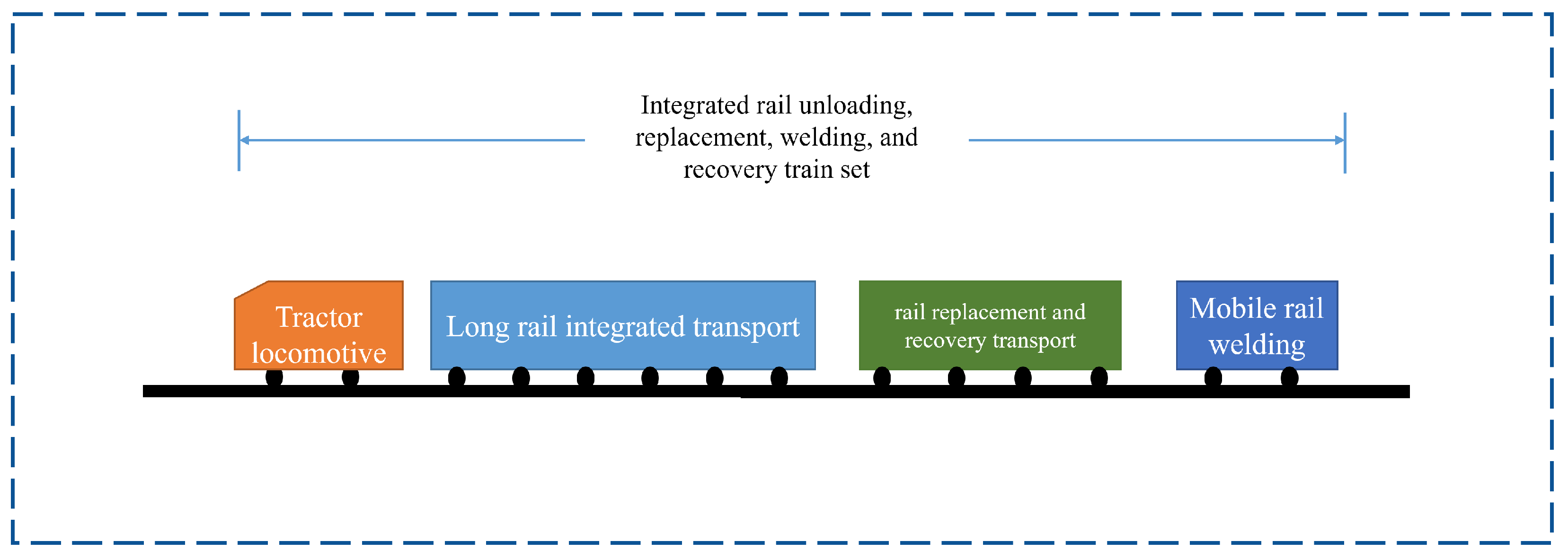
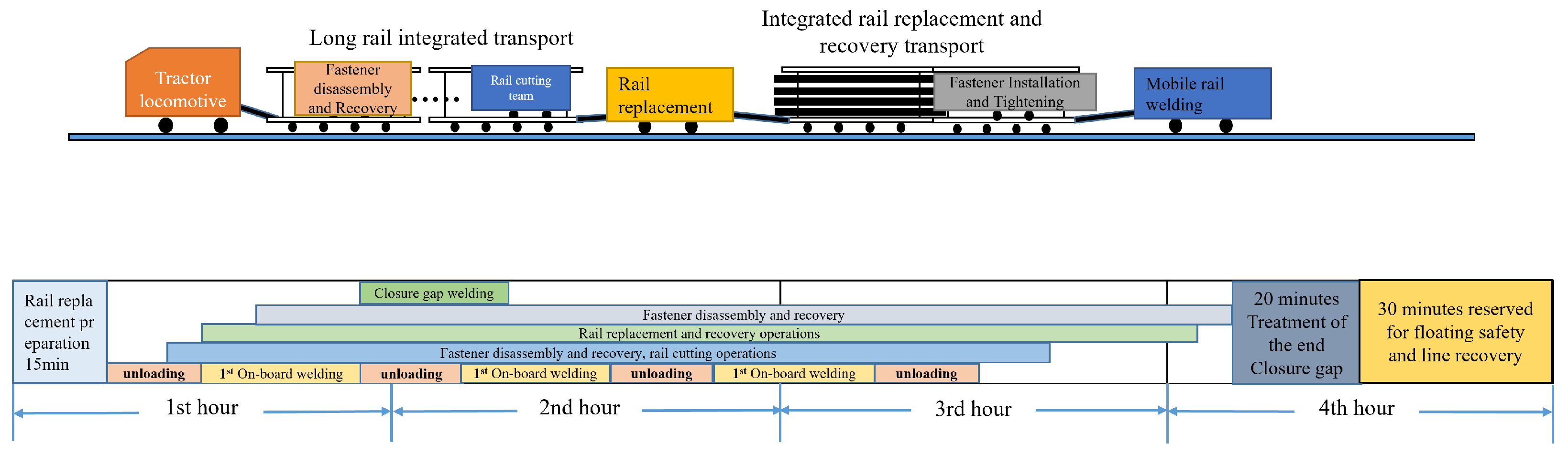
The integrated rail-changing train set is designed with the core philosophy of “functional integration and collaborative operation”. As illustrated in
Figure 1, the train set consists of four primary vehicle categories: the tractor, the long-rail comprehensive transport vehicle, the exchange-recovery integrated transport vehicle, and the mobile welding vehicle. Among these, the long-rail comprehensive transport vehicle and the exchange-recovery integrated transport vehicle are newly designed units that must be modified or redesigned based on specific rail-changing requirements.
Tractor: Serves as the power and scheduling hub, ensuring the precise movement and coordinated operation of the entire train set;
Long-Rail Comprehensive Transport Vehicle: Responsible for transporting 500 m new rails and coordinating rail unloading with on-board welding; it also carries the fastener disassembly/recovery and rail-cutting trolley groups;
Exchange-Recovery Integrated Transport Vehicle: Synchronously completes the recovery of old rails and the laying of new rails, utilizing an onboard tightening vehicle group to ensure the stability of the newly laid track;
Mobile Welding Vehicle: Handles rail butt-welding and closure welding to ensure the continuity of the track.
These four components form a full-process closed loop of “unloading, welding, exchange, and recovery,” thereby improving the coordination and mechanization level of rail-changing operations.
2.1. Tractor
The tractor serves as the power and scheduling hub of the integrated rail-changing train set [
13]. It tows the long-rail comprehensive transport vehicle and the exchange-recovery integrated transport vehicle, and it controls movement, positioning, and dispatching within the blocked section.
The tractor has four main functions in the proposed process:
Operational synchronization: it ensures that each vehicle group enters the work zone and starts its assigned task according to the planned sequence;
Velocity control: it maintains safe movement of the nearly 900 m train set while workers and auxiliary vehicles operate nearby;
Stability on challenging terrain: it must provide reliable traction on steep grades and other difficult alignments [
5,
14];
Constant low-speed movement: it should keep the whole train at about 1–3 km/h to support synchronized unloading, exchange, and recovery operations.
By serving as the movement-control center, the tractor helps prevent process decoupling and supports the parallel workflow of the integrated train set.
2.2. Long-Rail Comprehensive Transport Vehicle
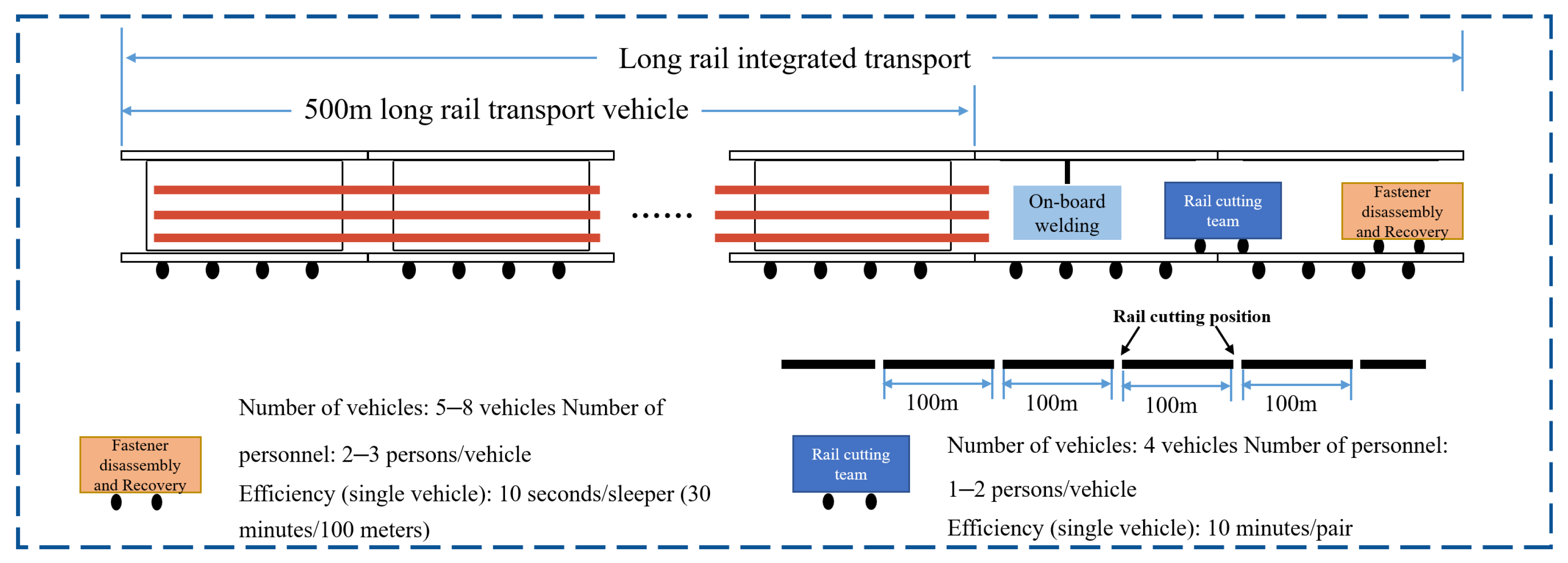
The long-rail comprehensive transport vehicle is designed to transport 500 m long rails while integrating unloading and on-board welding. As shown in
Figure 2, it also provides deployment space for the fastener disassembly/recovery trolley group and the rail-cutting trolley group. This arrangement reduces waiting time between unloading and welding and supports the parallel workflow proposed in this paper.
2.2.1. On-Board Welder
The core function of the on-board welder is to coordinate rail unloading and welding. During the unloading of 500 m new rails from the long-rail comprehensive transport vehicle, the on-board welder performs butt-welding so that welding does not have to wait until rail unloading is fully completed. It also works with the mobile welding vehicle to support the continuity and quality of the newly formed long-rail sections before rail exchange.
For on-site welding of 100 m rails, flash butt welding is selected because it can integrate de-rusting, welding, normalizing, straightening, grinding, and flaw detection within a relatively continuous workflow [
15,
16]. The resulting weld quality can satisfy the strength requirements of heavy-haul railways when verified through required quality tests, such as drop-weight tests.
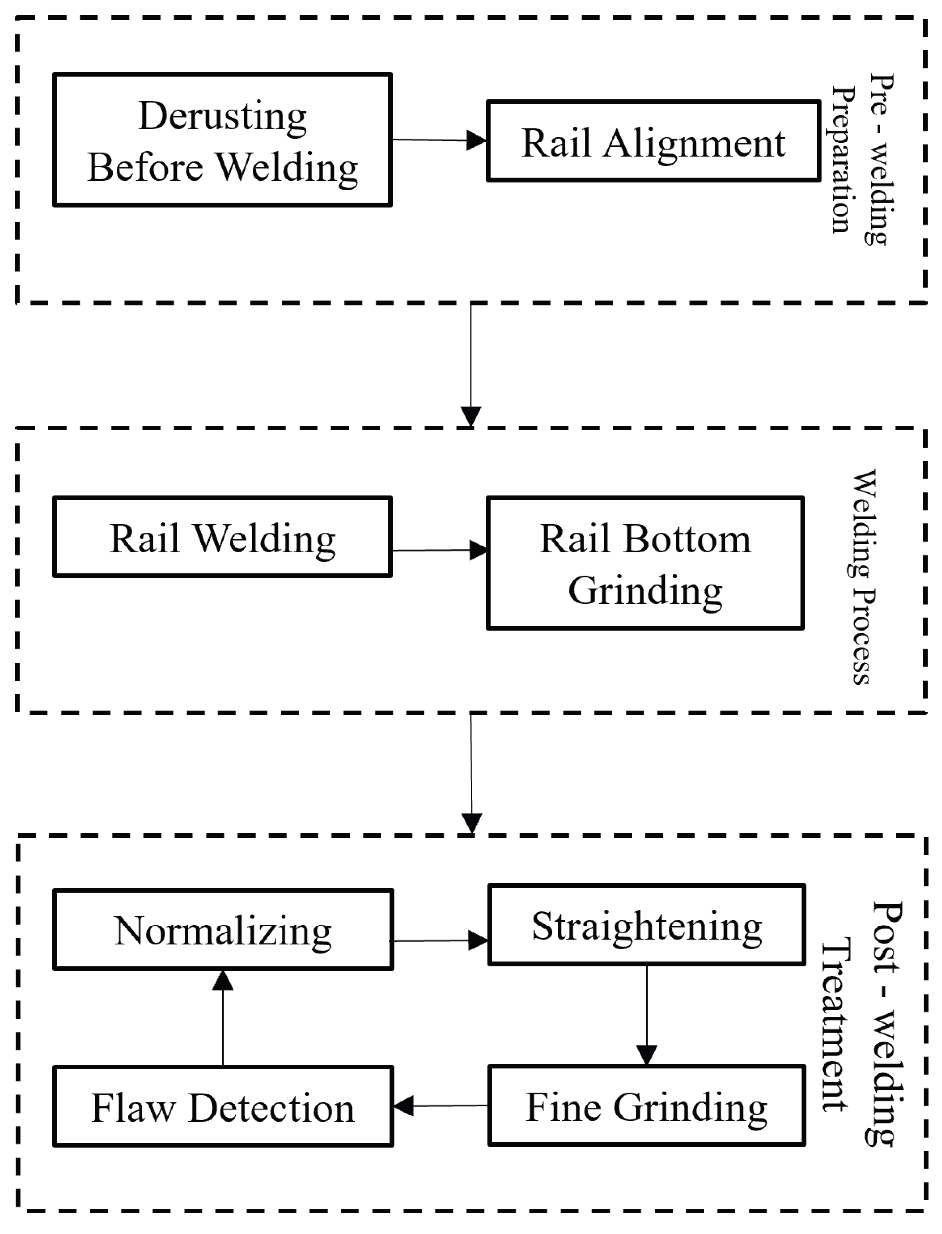
As shown in
Figure 3, the overall flash butt welding process consists of three stages: pre-welding preparation, the welding process, and post-welding treatment.
Pre-welding Preparation: Requires de-rusting the rails and performing rail alignment;
Welding Process: After welding is completed, air-spray cooling can be used to lower the rail temperature, followed by grinding the rail bottom and removing weld beads;
Post-welding Treatment: To improve the comprehensive mechanical properties of the flash butt weld, post-weld heat treatment is required [
17]. This includes normalizing, straightening, precision grinding, and final ultrasonic flaw detection.
Taking the modification of the YHG-500Q welding rail vehicle as an example [
18], through the adjustment of the vehicle layout and certain components such as power supplies and power compartments, it is possible to achieve one-time online welding, meeting the rail welding requirements of the long-rail comprehensive transport vehicle.
2.2.2. Fastener Disassembly and Recovery Vehicle
The fastener disassembly and recovery vehicle is responsible for the removal and collection of old-rail fasteners. During operation, the vehicle group departs from the long-rail comprehensive transport vehicle and advances along the track to remove and collect old-rail fasteners, such as elastic clips. This work is completed at an efficiency of about 10 s per sleeper, clearing obstacles for subsequent rail cutting and recovery [
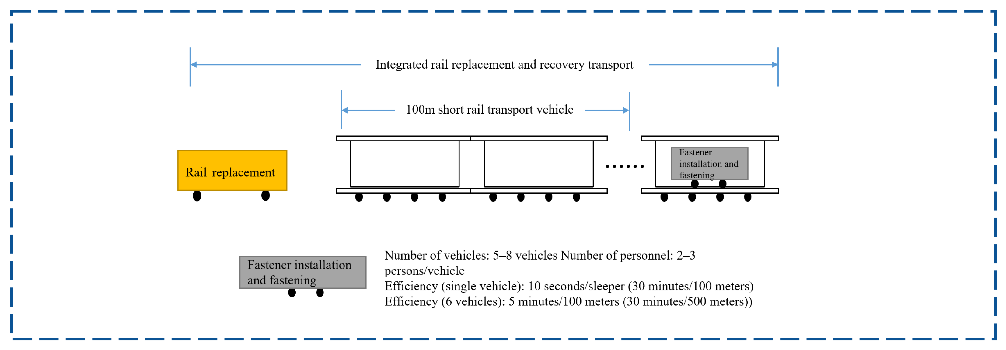
19]. Each long-rail transport vehicle is equipped with 5–8 disassembly and recovery vehicles, with each small vehicle staffed by 2–3 people for driving, monitoring, and residual fastener removal. When six vehicles work collaboratively, they can complete 100 m of operation in about 5 min, which allows fastener disassembly to keep pace with rail unloading and cutting.
Taking a specific type of domestic fastener disassembly trolley as an example [
20], it employs stepping operations to achieve continuous work and utilizes a positioning method combining visual detection and light-sensing detection to locate fasteners on the railway. This allows the system to obtain information such as the position and distance of spikes, as well as data on gauge baffles and baffle seats. Based on the collected information, various sets of wrenches are adjusted to achieve fastener disassembly, with a single operation cycle taking only 5.4 s. To be applied to the long-rail comprehensive transport vehicle, this disassembly trolley requires certain modifications, such as the installation of a fastener storage device.
2.2.3. Rail Cutting Vehicle Group
The rail-cutting vehicle group is deployed on the long-rail comprehensive transport vehicle and is responsible for cutting old rails into 100 m segments after fastener disassembly. The baseline process assumes that two rail-cutting resources can work in parallel, with each pair of rails requiring about 10 min to cut. Segmentation before exchange-recovery reduces the handling difficulty of long old rails and allows the short rail transport vehicle to collect the removed rails more efficiently.
In current practical rail replacement construction, rail cutting still relies heavily on manual labor, and specialized maintenance trains for automated rail cutting are not yet widely used. Therefore, the rail-cutting vehicle group should be regarded as a subsystem requiring further development or refinement. During transitional implementation, organized manual-assisted cutting teams may be used to maintain process continuity, but improving the reliability and mechanization level of rail cutting remains essential for reducing manual exposure and preserving the schedule advantage of the integrated process.
2.3. Exchange-Recovery Integrated Transport Vehicle
The exchange-recovery integrated transport vehicle is the core equipment for synchronized old-rail recovery and new-rail placement. As shown in
Figure 4, it integrates a rail-changing device, a short rail transport vehicle, and a fastener tightening vehicle group transport vehicle. Its core function is to remove 100 m old rails from the track and transfer them to the short rail transport vehicle while laying the new rails in the required position. The onboard fastener tightening vehicle group then performs initial fastening and tightening after the new rail is placed. With a single-vehicle efficiency of 10 s per sleeper, six vehicles working collaboratively can complete 100 m of operation in about 5 min.
2.3.1. Rail-Changing Vehicle
The rail-changing vehicle is responsible for old-rail removal and new-rail placement. Its design concept is adapted to the exchange and collection requirements of 100 m old rails. By using mechanical arms and track alignment technology, and by coordinating with the short rail transport vehicle, it removes old rails from the track and places new rails on the sleepers. This provides the geometric basis for subsequent fastener tightening and temporary track stability.
Most current rail-changing vehicles can only perform the exchange function and cannot complete the recovery of old rails simultaneously. For instance, the HGCZ-2000 rapid rail-changing vehicle widely used in China follows a sequence of unloading, exchange, tie plate replacement, fastener installation, rail temperature locking, welding, cutting, and finally, old-rail recovery [
6,
7]. This arrangement leads to low time utilization during the exchange phase. Similarly, the Japanese REX-S rail-changing system follows a staged process of rail unloading, welding, exchange, and closure welding, with process organization still separated by possession and task stage [
9,
10]. To adapt to the integrated process flow described in this paper, existing vehicles must be modified to enable integrated exchange and recovery functions.
2.3.2. Short Rail Transport Vehicle
The short rail transport vehicle temporarily stores the 100 m old rails recovered by the rail-changing vehicle. Its capacity is designed to satisfy the recovery demand of one 4 h maintenance window. During operation, it remains coordinated with the rail-changing device so that removed old rails can be collected immediately rather than accumulating on site. Two vehicles can be configured when necessary: one operates in the work zone, and the other remains on standby at a station track so that recovery can continue without interruption across consecutive windows.
2.3.3. Fastener Tightening Vehicle Group Transport Vehicle
The fastener tightening vehicle group serves as an equipment and personnel platform for securing new rails immediately after placement. This group typically comprises 5–8 specialized vehicles, with each unit staffed by 2–3 personnel. A single vehicle can operate at about 10 s per sleeper, equivalent to approximately 30 min per 100 m; when six vehicles work in coordination, the tightening of a 100 m section can be completed in about 5 min. During the exchange phase, the group implements a “skip-five-fix-one” fastening protocol, which installs one fastener at an interval of five sleepers to pre-fix the new rails. This approach restricts lateral rail displacement and helps maintain temporary track stability before comprehensive tightening is completed.
It should be noted that the fastener installation and tightening vehicle group is treated as a semi-automated target subsystem in the present study, rather than a fully mature unmanned device. At the current stage, automatic fastener feeding, accurate positioning, and torque-controlled tightening have not yet been fully validated as an integrated train-borne system. Therefore, the fastener installation process in this study is considered at the process-planning and time-estimation level. Manual assistance, local correction, fastener supply monitoring, and torque inspection are still retained as transitional measures.
2.4. Mobile Welding Vehicle
The mobile welding vehicle and the on-board welder shown in
Figure 2 have different functions in the proposed system. The on-board welder is installed on the long-rail comprehensive transport vehicle and is mainly used to weld newly unloaded rail sections during the rail unloading process, thereby supporting the continuous formation of long-rail sections before rail exchange. In contrast, the mobile welding vehicle shown in
Figure 1 is an independent welding unit responsible for supplementary rail welding and final closure welding at the beginning and end of the replacement section. It is operated by six welding personnel and works together with the on-board welding system of the long-rail comprehensive transport vehicle. In the proposed process, it completes the initial and final closure welds, with each single weld requiring about 25 min. Therefore, the on-board welder supports parallel unloading-welding operations, whereas the mobile welding vehicle ensures continuity between the newly laid long rails and the existing track.
2.5. Equipment Maturity and Automation Level
To clarify the implementation status of the proposed integrated rail-changing system, the maturity and automation level of each major assembly are summarized in
Table 1. The total length of the integrated rail-changing train set is approximately 900 m, of which the long-rail comprehensive transport vehicle accounts for about 660 m and the exchange-recovery integrated transport vehicle accounts for about 220 m. The proposed system should not be interpreted as a fully unmanned rail-changing system. Some assemblies can be adapted from existing railway maintenance equipment, some require modification for integration into the proposed workflow, and some fastener-related devices still require further dedicated development. In this study, automation mainly refers to mechanized or semi-automated assistance rather than completely unmanned operation. The human role in system operation includes supervision, equipment control, positioning confirmation, residual handling, quality inspection, and emergency intervention in several processes.
2.6. Engineering Integration Logic of the Proposed Train Set
The engineering novelty of the proposed system lies mainly in subsystem integration and workflow organization rather than in a single completely new machine. In conventional practice, unloading, welding, exchanging, and recovery are often assigned to separate vehicle groups and separated in time. This creates repeated waiting, multiple handover points, and inefficient occupation of the maintenance window. The proposed train set reorganizes these functions into a coordinated construction platform so that key operations can proceed in a staggered parallel mode.
The integration logic has three main elements. First, the long-rail comprehensive transport vehicle combines new-rail transportation, unloading, and on-board welding, which shortens the interval between rail delivery and welded-track formation. Second, the exchange-recovery integrated transport vehicle links old-rail removal, short-rail collection, and initial fastener installation, thereby reducing the interruption between rail exchange and track stabilization. Third, the tractor acts as the central scheduler that maintains spacing, sequence, and speed among the operating units.
This logic also depends on explicit interface relationships between subsystems. Fastener disassembly must stay ahead of rail cutting, rail cutting must stay ahead of old-rail recovery, and exchange-recovery must stay sufficiently behind the unloading front to maintain operational safety. The 100 m and 500 m nodes used in the process description serve as practical coordination points for releasing downstream operations, organizing on-board welding, and limiting interference between adjacent work groups. In this sense, the proposed train set is an integrated engineering scheme for time compression within a fixed maintenance window.
3. Integrated Construction Process and Collaborative Workflow
The proposed integrated rail-changing construction process is organized around process parallelism and coordinated scheduling. Within a 4 h maintenance window, the workflow is divided into preparation, core operation, and finishing stages. Under the scheduling of the tractor, rail unloading, welding, exchange, and recovery are organized in parallel together with fastener disassembly, rail cutting, and fastener tightening. The engineering time-study analysis and the discrete-event simulation results together indicate that this workflow can support the replacement of 2 km of track within one maintenance window under the specified assumptions.
3.1. Preparation Stage
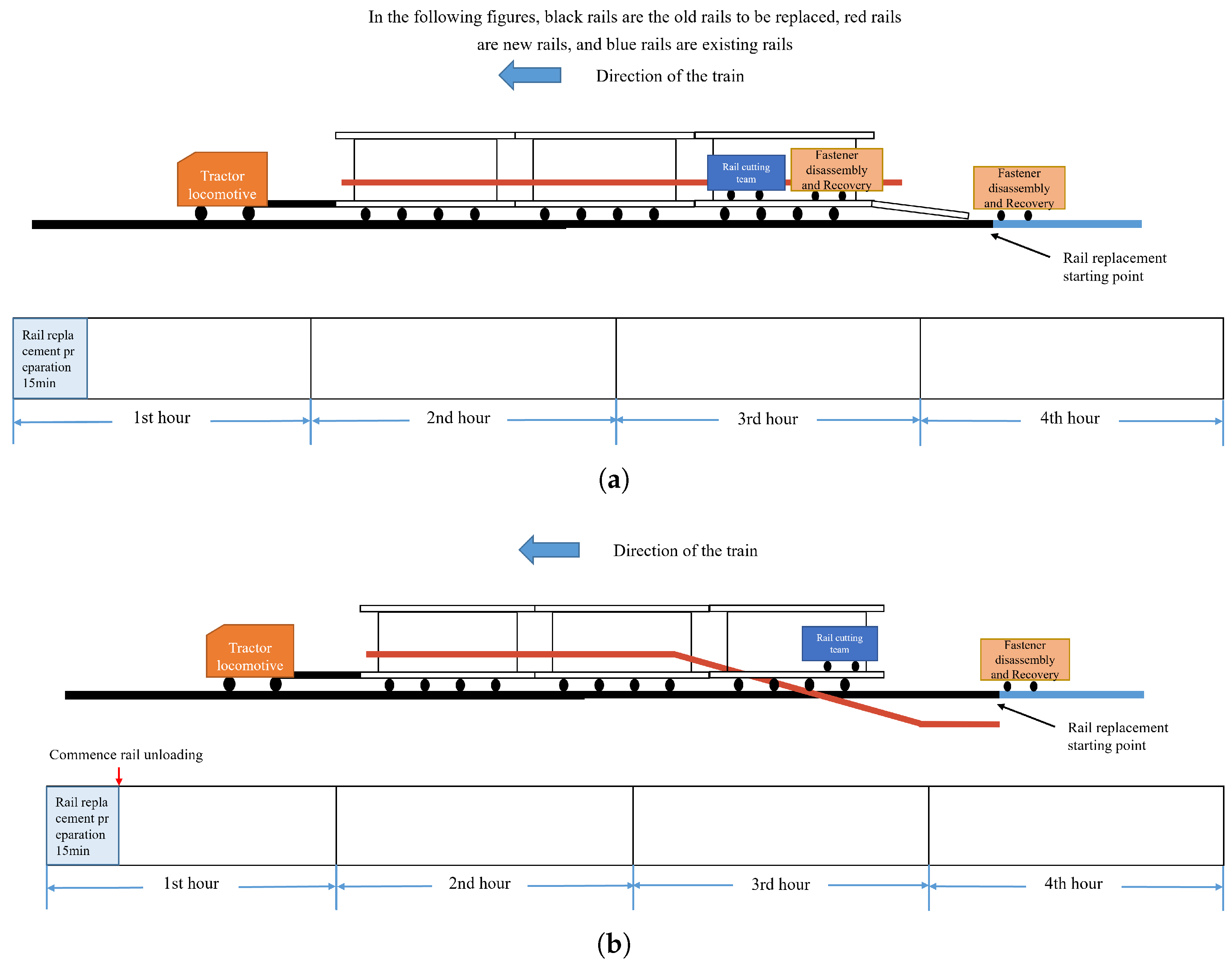
The preparation stage establishes the initial operating conditions for the subsequent parallel workflow, as illustrated in
Figure 5. During the first 15 min after the track possession begins, the integrated train set enters the work zone under the control of the tractor and is positioned at the planned starting point. The main tasks in this period include site confirmation, rail unlocking, adjustment of the rail-pulling device, deployment of the fastener disassembly/recovery trolley group, and preliminary checks of the rail unloading, welding, cutting, and rail-changing devices.
The exchange-recovery integrated transport vehicle and the mobile welding vehicle are then uncoupled at the initial closure joint and prepared for downstream operations. The fastener disassembly/recovery trolley group is positioned on both sides of the track after functional checks of the braking and disassembly units. Once the equipment is positioned and the main interfaces among unloading, disassembly, welding, and exchange-recovery have been confirmed, the long-rail comprehensive transport vehicle starts the rail unloading operation.
3.2. Core Operation Stage
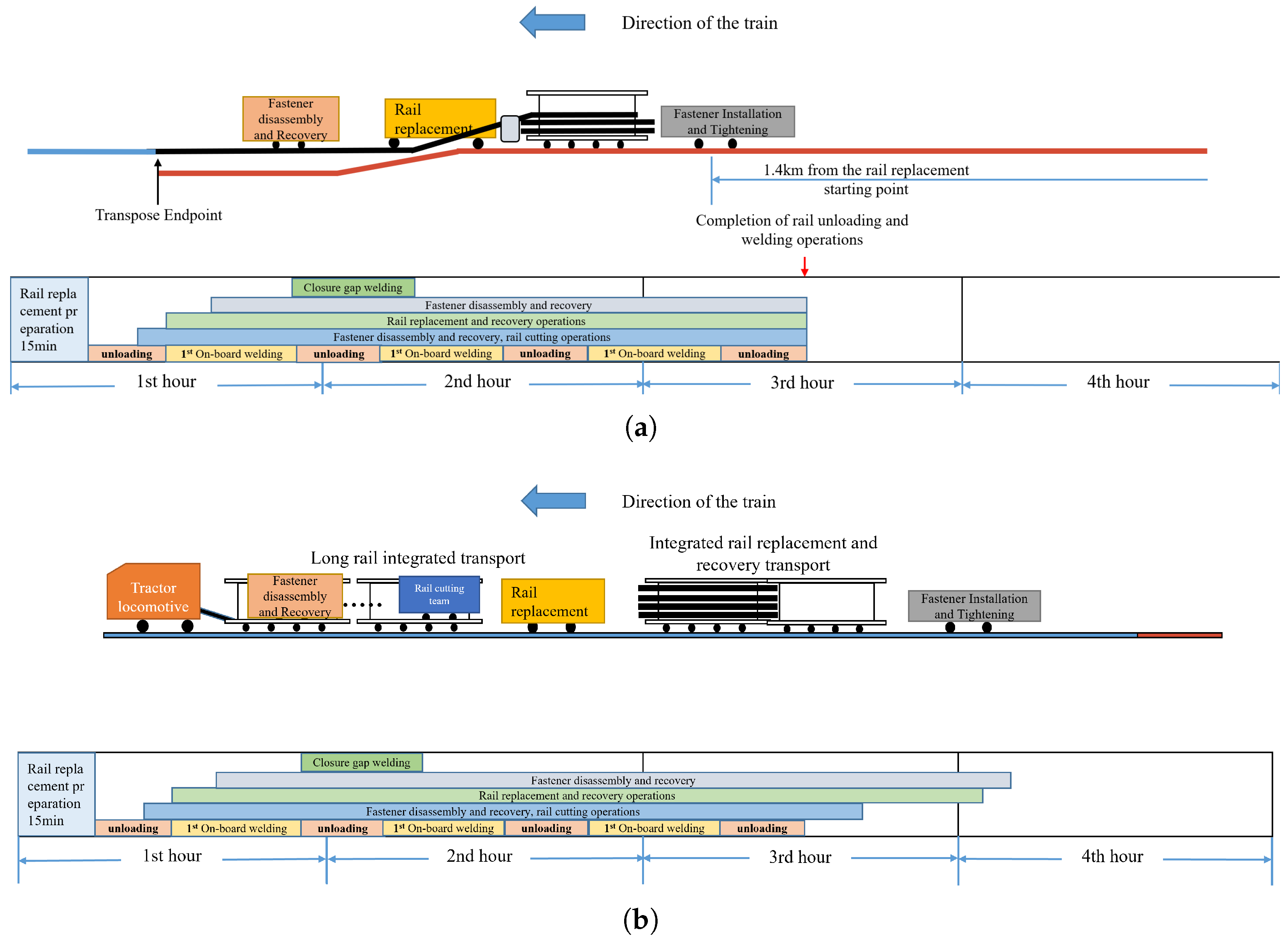
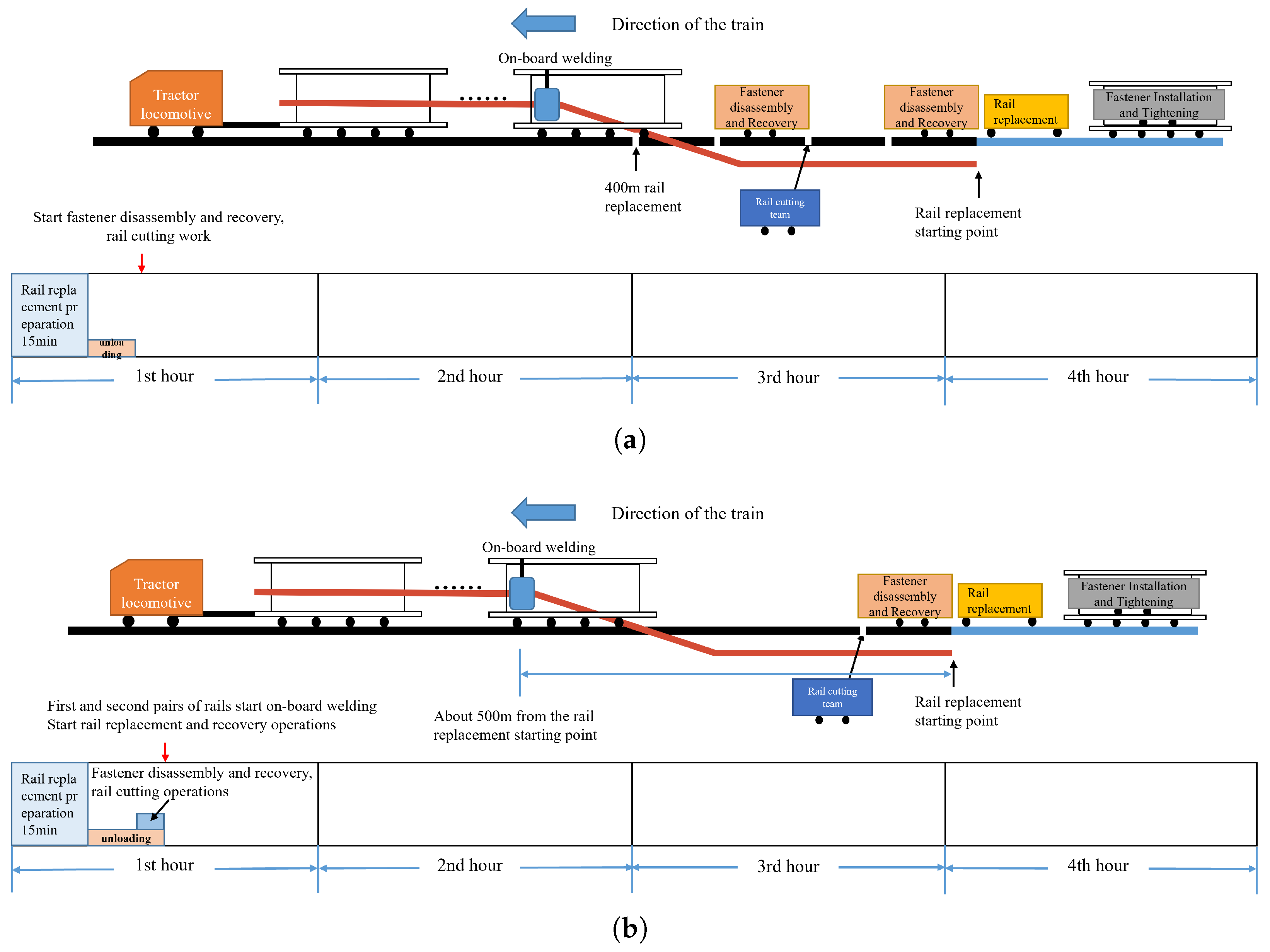
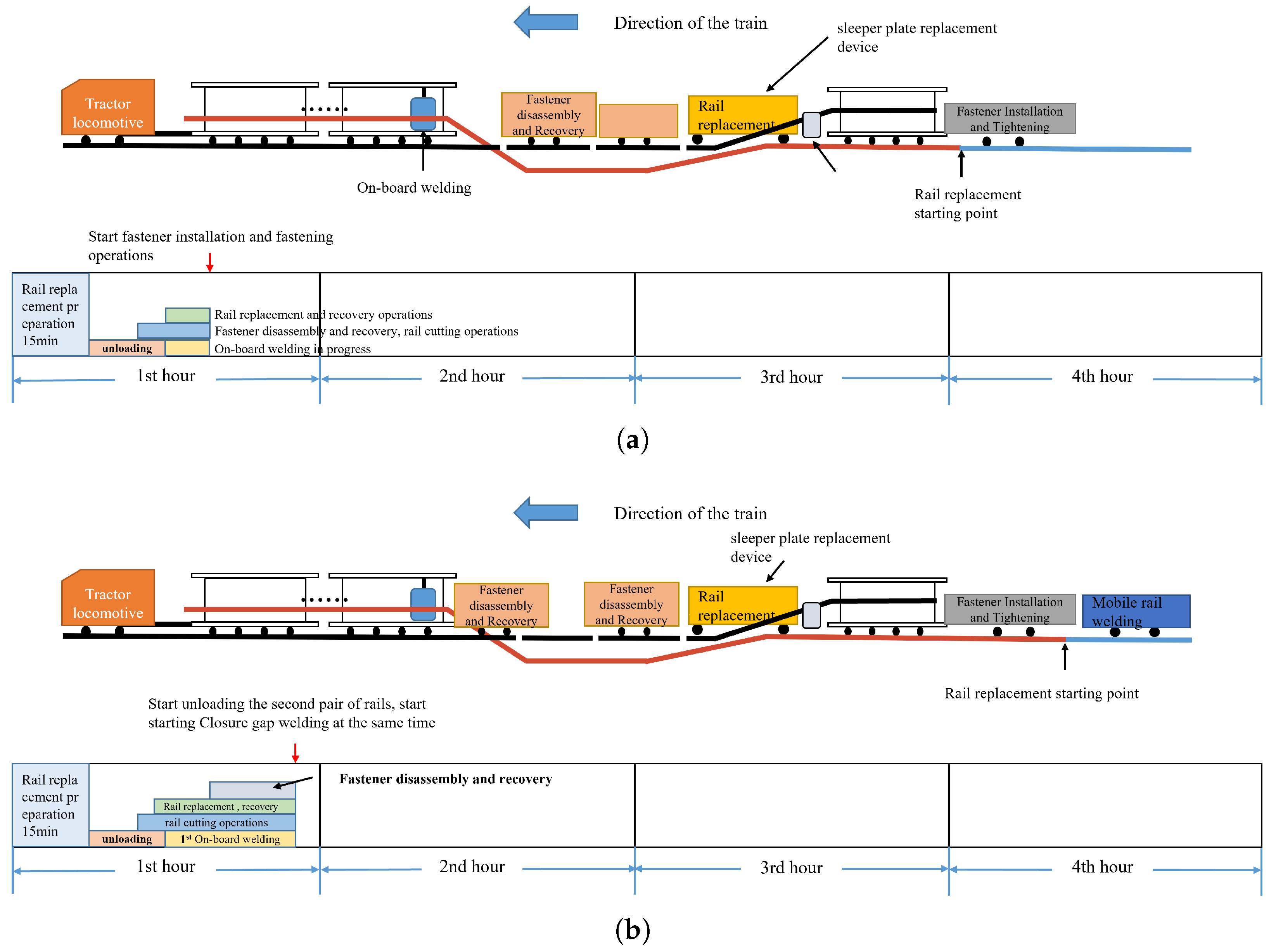
The core operation stage lasts for 2 h and 55 min and is the main execution phase of the integrated process. During this stage, multiple vehicle groups work in parallel, as shown in
Figure 6,
Figure 7 and
Figure 8. The long-rail comprehensive transport vehicle first starts rail unloading. As the unloading front reaches a safety distance of 100 m, the fastener disassembly/recovery trolley group and the rail-cutting trolley group start their assigned tasks. At the same time, the exchange-recovery integrated transport vehicle completes final preparation for entry into the work zone. The fastener disassembly/recovery trolley group removes old-rail fasteners at about 10 s per sleeper, while the rail-cutting trolleys cut the old rails into 100 m segments at about 10 min per pair of rails.
When unloading reaches the 500 m mark, the first 100 m of fastener disassembly and rail cutting has been completed. At this point, welding begins for the first and second pairs of rails, and the exchange-recovery integrated transport vehicle enters the operation zone to start old-rail removal and new-rail alignment, as shown in
Figure 6b. Tie plate replacement is completed during rail exchange. After the new rail is placed and before recovery progresses further, fastener installation and tightening are carried out using the “skip-five-fix-one” method to provide temporary fixation and maintain track stability. Once 100 m of exchange-recovery work is completed, the fastener installation trolley group starts comprehensive tightening, as shown in
Figure 7a. After on-board welding of the first and second 500 m rail pairs is finished, the mobile welding vehicle performs closure welding at the starting point while the other vehicle groups continue their assigned tasks.
By 2.5 h after the start of operation, the planned schedule indicates completion of about 2 km of rail unloading and welding, 1.8 km of fastener disassembly and recovery, 1.5 km of exchange-recovery, and 1.4 km of fastener tightening, as illustrated in
Figure 8a. Subsequent operations continue in parallel, and the whole integrated process is expected to finish at about 3 h and 10 min. The fastener disassembly/recovery trolley group and the rail-cutting trolley group then return to the long-rail comprehensive transport vehicle, while the fastener installation and tightening group prepares for return, as shown in
Figure 8b.
3.3. Finishing Stage
The finishing stage covers the period from 3 h and 10 min to 4 h after the start of operations. Its main tasks are equipment recovery, final closure welding, track inspection, and orderly withdrawal from the work zone, as shown in
Figure 9. After completing their main tasks, the fastener disassembly/recovery trolley group and the rail-cutting trolley group return to the long-rail comprehensive transport vehicle. At the same time, the fastener installation and tightening group prepares for return to the exchange-recovery integrated transport vehicle.
During this stage, the mobile welding vehicle performs final closure welding, which is estimated to require about 20 min. After welding, grinding, and flaw detection are carried out to confirm weld quality. A 30-min buffer is reserved for restoration inspection so that track smoothness, fastener tightness, and weld quality can be checked before reopening the line. Once all finishing work is completed, the vehicle groups are coupled and leave the operation area in an orderly manner.
3.4. Risk and Operational Constraints
The highly parallel workflow proposed in this paper can improve time utilization within the maintenance window, but it also introduces operational constraints that must be considered in practice. The first risk is process interference between adjacent work groups. Because unloading, fastener disassembly, rail cutting, exchange-recovery, and fastener tightening proceed in a staggered parallel mode, inadequate spacing or delayed response by one unit may affect the progress of downstream operations.
The second risk is synchronization failure caused by equipment malfunction, crew delay, or unexpected site conditions. If one subsystem cannot maintain its planned cycle time, the closed-loop schedule may be disrupted and the expected time advantage may be reduced. In addition, closure welding and final inspection remain critical control points because delays at the end of the maintenance window may directly affect line reopening.
The third issue is construction safety. Reducing the number of workers from about 340 to 80–95 can lower personnel density within the work zone, reduce cross-interference between teams, and decrease direct exposure to manually intensive tasks such as fastener removal, rail handling, rail cutting, and repeated movement near operating equipment. These factors are expected to improve construction safety. However, the integrated process also requires stricter discipline in movement control, communication, and emergency response because multiple operations are active at the same time.
Finally, the practical implementation of the proposed train set is constrained by equipment maturity. Some subsystems can be adapted from existing railway maintenance equipment, but others still require modification or dedicated development. In particular, the fastener disassembly/recovery trolley group and the fastener installation/tightening trolley group are not yet fully mature as integrated train-borne systems. Therefore, although the present study has included discrete-event simulation verification, future work should still include pilot application, field-data-based calibration, and risk assessment under real construction conditions.
4. Discrete-Event Simulation Verification
4.1. Simulation Model
To further evaluate the feasibility of the proposed integrated rail-changing process, a discrete-event simulation model was established. The simulation focuses on the construction organization process rather than the mechanical dynamics of rail handling or the thermal behavior of rail welding.
The simulated task is a 2 km rail-changing operation within a 4 h maintenance window. The whole section is divided into twenty 100 m construction units. Each unit passes through fastener disassembly, rail cutting, exchange-recovery, and fastener tightening. Rail unloading is modeled as a continuous operation along the work section, while on-board welding is modeled according to 500 m long-rail sections.
The main logic of the model follows the proposed staggered parallel construction process. Fastener disassembly must be completed before rail cutting, rail cutting must be completed before exchange-recovery, and fastener tightening can start only after the new rail is placed. In addition, exchange-recovery is allowed to start only when the rail unloading front has reached a sufficient safety distance. The detailed event logic, resource constraints, and safety-distance constraints used in the simulation model are described in the following subsection.
4.2. Event Logic and Resource Constraints
The discrete-event simulation model was developed according to the staggered parallel logic of the proposed integrated rail-changing process. In the model, each major construction operation is represented by a start event and a completion event. A start event can be triggered only when three conditions are simultaneously satisfied: the predecessor operation has been completed, the required resource is available, and the corresponding safety-distance condition is satisfied. Once an operation is completed, the occupied resource is released and the downstream operation is allowed to enter the event queue.
The main event logic and resource constraints are summarized in
Table 2. The baseline model assumes one unloading system, one fastener disassembly/recovery trolley group, two parallel rail-cutting resources, one exchange-recovery integrated vehicle, one fastener installation/tightening trolley group, one on-board welding system, one mobile welding vehicle, and one inspection team. Except for the rail-cutting operation, each resource can process only one operation at a time. If the required resource is occupied, the corresponding event waits until the resource becomes available. Therefore, the actual start time of each operation is jointly determined by precedence constraints, resource availability, and safety-distance constraints.
For the
k-th 100 m construction unit, the start time of operation
i is defined as:
where
is the start time of operation
i for construction unit
k,
is the completion time of the predecessor operation,
is the earliest time when the required resource becomes available, and
represents the safety-distance constraint between adjacent work groups.
The completion time of operation
i is calculated as:
where
is the operation duration. The main precedence constraints are expressed as follows:
The safety-distance constraint between rail unloading and exchange-recovery is defined as:
where
d denotes the number of 100 m construction units required as the safety spacing between the unloading front and the exchange-recovery operation. In the baseline setting, the safety spacing is introduced to prevent interference between the unloading front and the downstream exchange-recovery work group.
4.3. Simulation Parameters
The simulation parameters were determined by combining the current rail-changing workflow, discussions with field experts from Shuohuang Railway, and the processing capacity of existing or modified equipment described in the previous sections. Because large-sample field data for the proposed integrated process are not yet available, triangular distributions were used to represent expert-informed estimates with a minimum value, a most likely value, and a conservative maximum value. The most likely value represents the expected duration under normal coordinated operation. The minimum value represents favorable conditions, such as smooth equipment movement, stable positioning, and limited rework, whereas the maximum value represents conservative conditions involving coordination delay, manual adjustment, residual handling, equipment repositioning, or additional quality checking.
The time required for equipment mounting, dismounting, installation, commissioning, recovery, and withdrawal was included in the simulation as task-level auxiliary time. Specifically, equipment entry, positioning, uncoupling, trolley deployment, initial installation, and commissioning were included in the preparation time. Equipment recovery, trolley return, recoupling, withdrawal preparation, and reopening-related checks were included in the final recovery and inspection time. Therefore, the 4 h maintenance-window simulation includes both 100 m unit operation times and auxiliary equipment-handling times.
It should be noted that the proposed workflow is designed as an automated or semi-automated target process. Therefore, the degree of manual involvement is not quantified as an exact percentage in the present simulation. Instead, it is classified qualitatively according to its influence on operation-duration variability. The purpose of this classification is to clarify which operations are more sensitive to manual positioning, monitoring, correction, inspection, and confirmation. Accordingly, manual participation is reflected in the width of the triangular duration distributions, especially in the upper-bound values, rather than being modeled as an independent labor-resource layer.
As shown in
Table 3, high manual influence indicates that the operation time is strongly affected by manual positioning, equipment operation, inspection, or confirmation. Medium manual influence indicates mechanized or semi-automatic operation with manual supervision, correction, or auxiliary handling. These qualitative levels were considered when setting the difference between the minimum and maximum operation times. Future field data will be needed to further calibrate these labor-related parameters.
4.4. Evaluation Indicators
The performance of the proposed process is evaluated using total construction time, probability of successful completion, equipment utilization, waiting time, and schedule buffer.
The total construction time is defined as the completion time of the final recovery and inspection operation:
The process is considered successful if the total construction time does not exceed the 4 h maintenance window:
The probability of completing the 2 km rail-changing task within the 4 h maintenance window is defined as:
where
is the success probability,
N is the number of Monte Carlo replications,
is the total construction time of the
r-th replication, and
is an indicator function.
The utilization rate of resource
j is calculated as:
where
is the utilization rate of resource
j,
is the total busy time of resource
j, and
is the capacity of resource
j.
The schedule buffer is defined as:
where
B is the remaining time buffer before the end of the maintenance window.
5. Simulation Results and Discussion
5.1. Baseline Simulation Result
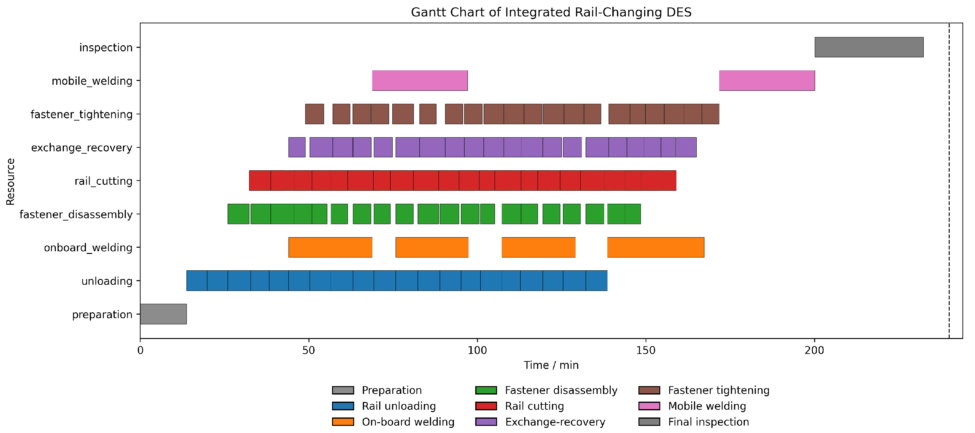
Figure 10 shows the Gantt chart of the baseline simulation. The horizontal axis represents simulation time, and the vertical axis represents the resources or operation groups. Each bar represents one simulated operation event occupying the corresponding resource during a specific time interval. The colors indicate different operation types, as shown in the legend. The dashed vertical line represents the 240 min maintenance-window limit.
The result indicates that the proposed integrated process has the potential to complete the simulated 2 km rail-changing task before the end of the 4 h maintenance window under the baseline parameter setting. The chart also shows that rail unloading, on-board welding, fastener disassembly, rail cutting, exchange-recovery, and fastener tightening are not performed sequentially, but are organized in a staggered parallel manner. This parallel organization is the main reason why the simulated total construction time can be compressed into one maintenance window.
5.2. Monte Carlo Simulation Result
To consider the influence of operation-time uncertainty, 1000 Monte Carlo simulation replications were conducted. The results are shown in
Table 4. The average total construction time was 228.3 min, and the probability of completing the simulated 2 km task within 240 min was 99.7%. The result suggests that the proposed process may have certain robustness under stochastic operation conditions. However, these results are conditional on the assumed input distributions and resource constraints. If the 95th percentile of total construction time is close to or greater than 240 min, the schedule buffer should be considered insufficient.
5.3. Sensitivity and Bottleneck Analysis
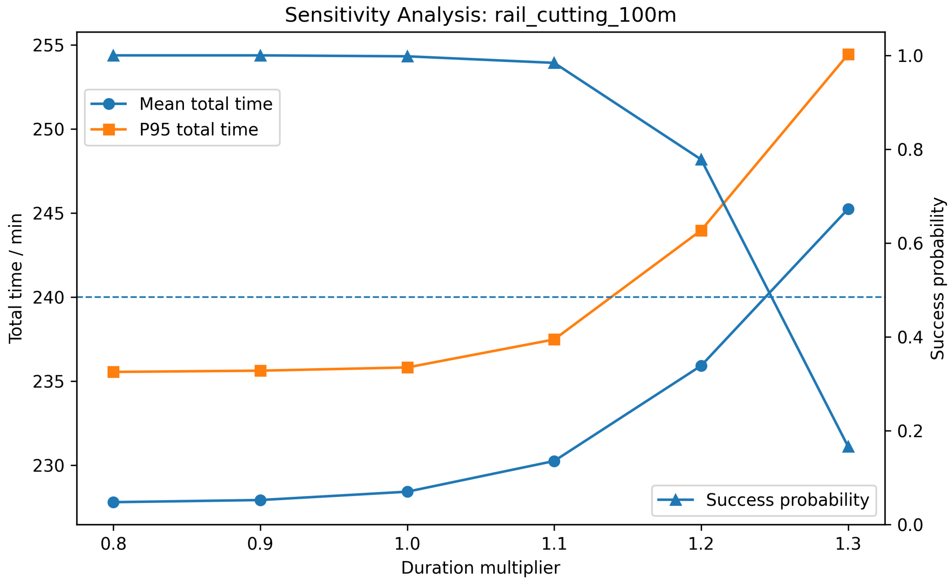
Figure 11 shows the sensitivity analysis of rail-cutting duration. When the rail-cutting duration increases, both the mean total construction time and the 95th percentile total construction time increase. Meanwhile, the probability of completing the task within the 240 min maintenance window decreases. When the rail-cutting duration increases to 120% of the baseline value, the 95th percentile total construction time exceeds the maintenance-window limit. When the duration increases to 130%, the mean total construction time also exceeds the maintenance-window limit, and the success probability decreases sharply. This indicates that rail cutting is an important schedule-control operation in the integrated rail-changing process.
To further respond to the concern that fastener-related operations may also affect the overall construction progress, additional sensitivity tests were conducted for fastener disassembly and fastener installation/tightening. Rail cutting was retained as a reference operation, and closure welding was also included because it directly affects the final connection and line reopening. In each test, the duration of one operation was increased by 20%, while the other parameters remained unchanged. The results are shown in
Table 5.
The results indicate that rail cutting is not the only operation that affects schedule robustness. When the duration of fastener disassembly increases by 20%, the 95th percentile total construction time reaches 241.9 min, exceeding the 240 min maintenance-window limit. When the duration of fastener installation and tightening increases by 20%, the 95th percentile total construction time reaches 243.7 min, and the success probability decreases to 81.4%. These results show that fastener-related operations have a clear influence on the continuity and robustness of the integrated workflow.
Compared with fastener disassembly and closure welding, rail cutting and fastener installation/tightening show stronger impacts on the success probability under the same +20% duration disturbance. Therefore, in addition to rail cutting, fastener disassembly and fastener installation/tightening should also be treated as key control points in future equipment development and field implementation. In particular, improving automatic fastener removal, fastener feeding, positioning, and torque-controlled tightening is necessary for maintaining the schedule advantage of the proposed integrated process.
6. Conclusions
This study should be understood as construction-process modeling, workflow organization, and simulation-supported feasibility analysis for heavy-haul railway rail replacement, rather than the development or field validation of a fully mature rail-changing machine. Based on this positioning, an integrated rail-changing workflow was organized to coordinate rail unloading, on-board welding, fastener disassembly, rail cutting, exchange-recovery, fastener installation and tightening, closure welding, and final inspection within a short maintenance window. The proposed workflow is based on 100 m construction units and 500 m long-rail welding units. Its purpose is to reduce process handovers, increase maintenance-window utilization, and lower personnel density in the work zone under specified operating assumptions.
The discrete-event simulation results indicate that, under the specified input distributions, resource constraints, and safety-distance assumptions, the proposed workflow has the potential to complete a simulated 2 km rail-changing task within a 4 h maintenance window. In the Monte Carlo simulation with 1000 replications, the mean total construction time was 228.3 min, the 95th percentile total construction time was 235.8 min, and the success probability within the 240 min window was 99.7%. These results suggest that the proposed workflow may be feasible under organized operating conditions, but the remaining schedule buffer is limited and depends strongly on the reliability of key operations.
The estimated personnel allocation further shows the labor reduction potential of the integrated workflow. The tractor requires four operators. Within the long-rail comprehensive transport vehicle group, rail unloading requires ten onboard personnel and ten ground coordination personnel; the on-board welder requires twelve operators; the fastener disassembly and recovery group requires 10–15 personnel; and the rail-cutting trolley group requires 4–8 personnel, giving a subtotal of 46–55 people. For the exchange-recovery integrated transport vehicle, exchange-recovery requires 10 people, tie plate replacement requires 2 people, and the fastener installation and tightening vehicle group requires 12–18 people, giving a subtotal of 24–30 people. The mobile welding vehicle requires 6 operators. Therefore, the total labor demand is estimated at 80–95 personnel, compared with about 340 personnel in the existing process.
The sensitivity analysis shows that the schedule robustness of the proposed workflow is mainly affected by rail cutting and fastener installation/tightening. When the duration of rail cutting or fastener installation/tightening increases by 20%, the success probability decreases substantially, and the 95th percentile total construction time exceeds the maintenance-window limit. Therefore, future equipment development should not focus only on the main rail-changing vehicle, but should also improve automatic rail cutting, fastener removal, fastener feeding, positioning, and torque-controlled tightening.
As discussed in the equipment maturity analysis, the proposed train-set configuration combines existing equipment, modified equipment, and assemblies that still require further development. In particular, the fastener disassembly/recovery trolley and the fastener installation/tightening device are not yet mature as fully integrated train-borne automatic systems. Therefore, the present study demonstrates process-level and simulation-supported feasibility rather than field-validated machine performance or immediate full-scale implementation readiness.
A comparison between the existing rail-changing technology and the proposed integrated workflow is shown in
Table 6. The baseline data for the existing process are taken from current rail replacement practice on Shuohuang Railway and are consistent with engineering experience from similar Chinese railway projects.
From a safety perspective, reducing the on-site workforce from about 340 to 80–95 may lower personnel density within the blocked section, reduce cross-interference among work groups, and decrease direct worker exposure to manually intensive tasks. However, the higher degree of parallelism also requires stricter movement control, communication, emergency response, and equipment-condition monitoring. Therefore, the proposed workflow should not be interpreted as a full-scale construction scheme that has already been validated in practice. Pilot implementation, field-data-based calibration, and dedicated field validation are still required before practical deployment.
Future optimizations can be further explored in several areas:
Enhance equipment automation: Focus on developing semi-automated or automated fastener disassembly and tightening systems;
Expand train-set adaptability: Meet the rail-changing requirements for different track profiles, such as 60 kg/m and 75 kg/m rails;
Integrate intelligent scheduling systems: Achieve dynamic time optimization for train-set operations.
Overall, this study provides a technical reference for construction-process organization and simulation-supported feasibility analysis in heavy-haul railway maintenance. It also identifies the need for future pilot validation, field-data calibration, and refinement of integrated rail-changing operations under real construction conditions.