1. Introduction
The demand for accurate and high-performance drive systems has been increased aligned with the rapid progress and massive adoption of electric vehicles (EVs). Induction motors (IMs) are still applied in traction applications due to their reliability, simplicity, low-cost design and little maintenance need [
1,
2]. Nevertheless, one major concern lies in the susceptibility of power electronic converters, especially the conventional three-phase six-switch inverter (6-SI), to faults that can seriously affect the overall system reliability and, in turn, the safety of the vehicle.
Traction inverters used in electric vehicles (EVs) operate under far more dynamic and safety-critical conditions than those employed in conventional industrial drives. They are required to manage wide variations in motor speed, enable bidirectional power transfer during regenerative braking, and comply with stringent thermal and functional safety standards such as ISO 26262. At the same time, EV designers try to simplify the hardware architecture and decrease both cost and weight by reducing redundant components. These requirements highlight the importance of developing a fault ride-through (FRT) control scheme appropriate for EV traction systems.
In practical EV applications, inverter switches can face different kinds of faults. These faults include open circuits, gate-driver problems, and partial failures in one inverter leg. Such issues can suddenly stop the operation of drive systems, which not only affects vehicle safety but also reduces the usage of EVs [
3,
4]. Since EVs are becoming more common, enhancing the fault tolerance of the drive systems is a crucial need to keep their reliability.
Several methods for reducing the impact of inverter faults were explored in previous studies. Conventional approaches primarily rely on the addition of additional hardware, such as parallel drive units or spare inverter legs. Other design methods may add circuits that can detect and isolate faults. These techniques can significantly improve the reliability, but they tend to increase the overall system cost, complexity, and size [
5].
Recent approaches focus on inverter reconfiguration. In these methods, the traditional six-switch inverter (6-SI) is converted into a four-switch three-phase inverter (FSTPI) when a fault occurs in one of its legs. Even though this setup offers fewer voltage vector choices, it can also keep the motor operating with good performance during faults. This makes it a simple and cost-effective backup option for EV traction systems [
6,
7].
In recent years, researchers have been interested in improving how EV traction inverters detect and handle faults. For instance, reference [
8] offered a comprehensive study about the latest advances in traction drive diagnostics, assuring the need for software-based fault management methods. Following this direction, study [
9] introduced a predictive control plan for multilevel inverter systems, which achieved precise current tracking even in the case of open-switch fault. Likewise, reference [
10] explored how fault-tolerant control can be utilized practically to induction motor drives, offering insights into the challenges of adapting controllers and managing their computational demands.
Based on this foundation, the present study introduces a new fault-ride-through (FRT) strategy tailored for induction motor drives in EVs. The suggested technique makes it possible to swiftly switch the inverter’s topology from 6-SI to 4-SI if a malfunction is identified. By doing this, the motor keeps running without the need for further hardware. In order to preserve torque output and speed stability during post-fault operation, a specialized pulse-width modulation (PWM) method is created in conjunction with the vector control (VC) algorithm. Compared with traditional techniques, the proposed study assures high performance control throughout the recovery period. This offers a cost-effective way toward fault-tolerant EV traction systems.
The key contribution of this work focuses on forming a software-oriented reconfiguration framework for three-phase traction inverters. This framework aims to eliminate the need for any additional sensing hardware and to maintain healthy operation, while keeping hardware costs low and showing consistent performance under various dynamic conditions relevant to electric vehicle operation.
2. Background and Related Work
2.1. Inverter Topologies in EV Drives
In electric vehicle (EV) systems, three-phase voltage source inverters (VSIs) are typically used to control the motor’s speed and torque. The six-switch inverter (6-SI) is compatible with advanced control techniques such as vector control (VC) and direct torque control (DTC) [
11,
12]; therefore, it remains the industry standard. Each inverter leg has a pair of switches and it governs one motor phase. This guarantees independent regulation of the corresponding phase current.
On the other hand, the four-switch inverter (4-SI) topology has recently gained attention as a cost-efficient alternative in case of fault-tolerant operation. In this case, one inverter leg is eliminated, and the associated motor phase is joined to a neutral point. It helps decreasing the number of components and providing a compact backup mode in the event of inverter faults. Although this configuration offers fewer voltage vector combinations, it remains a practical option for keeping operation under degraded conditions [
13]. This is so critical when maintaining system continuity is more important than realizing full control flexibility.
2.2. Induction Motor Control Strategies
Electric vehicle (EV) induction motors can be operated using a variety of control strategies. Scalar control (V/f), direct torque control (DTC), and vector control (VC) are some of these methods. Although the V/f technique is simple to use, its dynamic reaction is limited. Although DTC is known for its quick torque regulation, it can cause flux and torque ripples [
14,
15]. Additionally, by decoupling the regulation of torque and flux, VC provides precise and reliable performance, making it appropriate for EV traction applications under both normal and problematic circumstances [
14].
2.3. Fault-Ride-Through (FRT) Techniques
Numerous FRT techniques have been created to increase the dependability of motor drives that are powered by inverters. For instance, adding more inverter legs and using hardware-based redundancy approaches can successfully reduce faults, but at the expense of cost and complexity [
16]. While other methods, such as the use of capacitors or free-wheeling diodes, are easy to install, their transient performance is limited. Active reconfiguration techniques, on the other hand, rely on quick defect identification and inverter topology modification. However, the high computing demands of real-time processing frequently limit their practical realization [
17].
2.4. Reconfiguration-Based Control
Instead of requiring additional hardware components, recent research attempts have concentrated on using software to modify the inverter topology reconfiguration. This enhances structural simplicity and cost effectiveness. However, when a defect arises, some of these software-based methods are not very flexible in terms of control performance. The 4-SI operating mode, which limits post-fault performance in practical applications, has only been included in a small number of research [
18]. As a result, creating FRT strategies that maintain strong control capability and operational continuity is a significant task.
2.5. Gaps in the Literature
In order to overcome the drawbacks of earlier methods, this study presents a dynamic FRT solution that completely maintains the vector control (VC) framework while reconfiguring the inverter into a 4-SI topology. Unlike conventional approaches that rely on hardware redundancy or simplified post-fault control, the proposed solution uses software-based coordination to achieve adaptive PWM adjustment and real-time fault isolation. Dynamic simulations are used to validate the success of the suggested strategy, showing improved control continuity and dependability. A comparative overview of this work and previous research is given in
Table 1, which highlights its benefits in terms of cost effectiveness, control performance, and implementation viability.
To overcome the limitations found in earlier methods, this study presents a dynamic FRT strategy that reconfigures the inverter into a 4-SI topology while keeping VC structure successfully. Unlike traditional approaches that depend on adding hardware components, the proposed approach performs real-time fault isolation and adaptive PWM through software coordination. The approach’s effectiveness is assured through dynamic simulations, which show enhanced reliability and smoother control operation.
Table 1 summarizes how this work compares with previous studies, highlighting its strengths in cost efficiency, control performance, and ease of implementation.
2.6. Recent Advanced Control Strategies for Fault Tolerant Induction Drives
In recent years, several nonlinear and predictive strategies have been investigated to enhance the fault-tolerant performance of inverter-fed induction-motor drives. Sliding-mode control (SMC) achieves strong robustness against parameter variations and disturbances but may induce torque oscillations due to chattering. Backstepping and adaptive schemes offer improved transient precision yet require extensive state feedback and higher computational effort, which complicates embedded EV implementation. Model-predictive control (MPC) has gained popularity for its fast response and constraint handling but at the expense of computational load and parameter sensitivity [
19,
20,
21,
22,
23,
24]. Compared with these methods, the present software-centric vector-control reconfiguration achieves an effective compromise between simplicity, cost, and post-fault stability by reusing the existing control structure without additional sensors. Similar trends toward software-based and predictive fault tolerance have been reported in recent studies [
8,
9,
10], underscoring the relevance of the proposed framework to current EV traction research.
3. System Description and Fault Model
3.1. Description of the EV Induction Motor Drive System
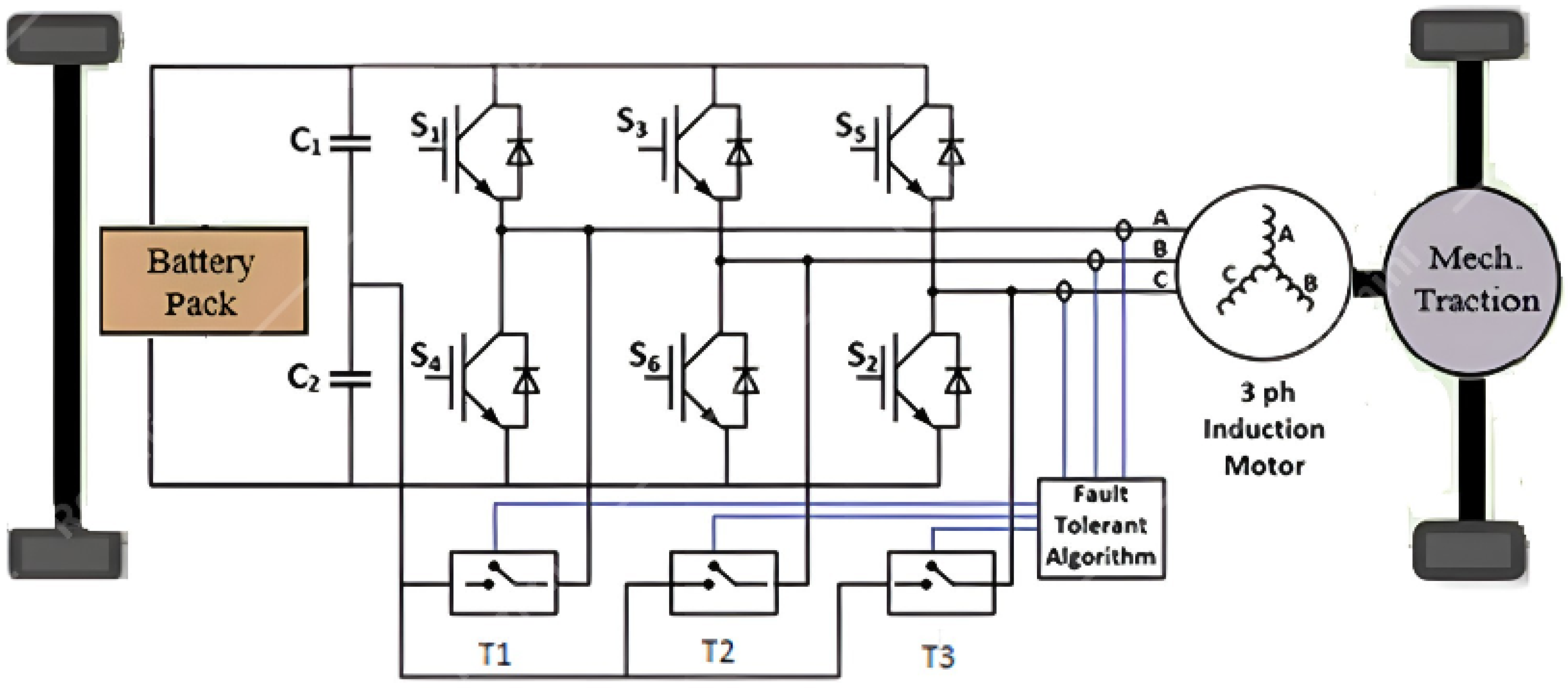
The EV drive system considered in this study consists of a three-phase squirrel cage induction motor powered by a conventional two level 6-SI voltage source inverter. The inverter is supplied by a DC battery pack and generates variable voltage and frequency outputs to control the motor. Torque and speed regulation are achieved via a standard VC strategy. The closed loop system includes a PI-based speed controller and two current regulators, which produce voltage references for pulse-width modulation (PWM) control.
To facilitate fault tolerance, the DC-link is split into two series-connected capacitors to form a virtual neutral point. Three MOSFETs (T1, T2, T3) are connected between this midpoint and the midpoints of the three inverter legs. When an open switch fault is detected in any leg, the system reconfigures itself into a 4-SI mode by disabling the faulty leg and activating the corresponding MOSFET. This MOSFET-based clamping restores current continuity in the affected motor phase.
While the reconfiguration reduces the available voltage vector space, it allows continued motor operation. The VC and PWM schemes are dynamically adjusted to accommodate the new inverter structure and maintain acceptable control performance.
Figure 1 illustrates the system architecture, including the inverter layout and the fault-tolerant reconfiguration mechanism.
Table 2 summarizes the switching and clamping states under different operating conditions.
The induction motor dynamics are described in the synchronous reference frame using the dq axis model. All symbols are defined in the nomenclature section, including stator/rotor inductances, flux linkages, pole pairs (P), and angular velocities.
Motor Modeling in the Synchronous Reference Frame.
The induction motor dynamics are described in the synchronous reference frame using the
dq axis model [
22].
where
3.2. System and Motor Design Parameters
The EV drive system modeled in this paper employs a 30 kW, three-phase squirrel cage induction motor designed for medium-power EV applications such as compact passenger cars and light commercial vehicles. The motor operates from a 400–700 V DC bus supplied by a lithium-ion battery pack and is driven by a two-level voltage source inverter (VSI) capable of reconfiguring to a four-switch topology under fault conditions. This configuration ensures high efficiency, torque density, and fault tolerance suitable for traction environments.
Table 3 presents the key electrical and mechanical parameters of the induction motor, including stator and rotor resistances, inductances, and the moment of inertia. Datasets of industrial-grade traction motors are used in deriving these parameters and they are verified through comprehensive MATLAB (version 2023b)/POWERSIM simulations. The inverter switching frequency was set to 10 kHz, which is an optimized value for IGBT-based traction converters in the power range of 30–50 kW.
The control system applies a VC strategy including both inner current and outer speed control loops. The PI controller gains were tuned to achieve fast transient response, minimal overshoot, and stable torque regulation under both healthy and faulty inverter conditions. All performance quantities in the simulation, such as torque, current, and speed, are expressed in per-unit (p.u.) values based on the rated quantities of the selected 30 kW induction motor to ensure generality and scalability of the results.
3.3. Vector Control of EVs in Healthy Operation
Under healthy operating conditions, the EV’s induction motor drive employs a standard VC, to achieve high performance speed and torque regulation. The VC technique transforms the three phase stator currents into the rotating dq reference frame using the Clarke–Park transformation, allowing decoupling of the torque producing and flux producing components. This decoupling is essential for precise control, enabling independent adjustment of rotor flux and electromagnetic torque.
Mathematical Equations for VC of a 6-SI Three-Phase:
The
dq current PI controllers generate voltage commands.
The outer loop regulates speed by generating the torque reference:
The rotor flux angle
θ used for coordinate transformation is computed by integrating the sum of rotor speed and slip frequency.
The slip frequency is computed from:
The direct-axis current reference
is set to maintain the desired rotor flux.
To convert voltage references back into the stationary frame:
The healthy-mode VC architecture offers fast, dependable, and fully decoupled torque and flux control, providing a strong basis for assessing performance degradation in fault scenarios. Its modular control structure, which comprises well-defined inner and exterior control loops, provides a solid foundation for dynamic reconfiguration during inverter failure occurrences.
When operating normally, VC architecture guarantees quick, steady, and complete management of both torque and flux. It also assesses how performance varies when faults occur. If inverter failures occur, its modular design, which includes inner and outer control loops, provides a framework for dynamic reconfiguration.
3.4. Fault Types Considered
In inverter-fed induction motor drives used in EV applications, various fault conditions can be considered as a result of thermal stress, semiconductor aging, or even irregular control signal. Among these, open-circuit faults and gate-drive failures are the most common and represent major threats to system reliability and operational safety. This study concentrates on these high-impact and frequently occurring fault types, ensuring that the proposed mitigation strategy effectively targets the most critical vulnerabilities affecting traction drive continuity in EVs.
3.4.1. Open-Circuit Switch Faults
An open-circuit fault takes place when one or both of the inverter’s power switches, whether IGBTs or MOSFETs, stop conducting current. This usually happens because of excessive heat, lifted bond wires, or damage inside the device itself. When it occurs, the current path in that motor phase is broken, which leads to:
Discontinuous stator currents;
Torque pulsations and acoustic noise;
Degraded dynamic performance;
Potential instability if left unmitigated.
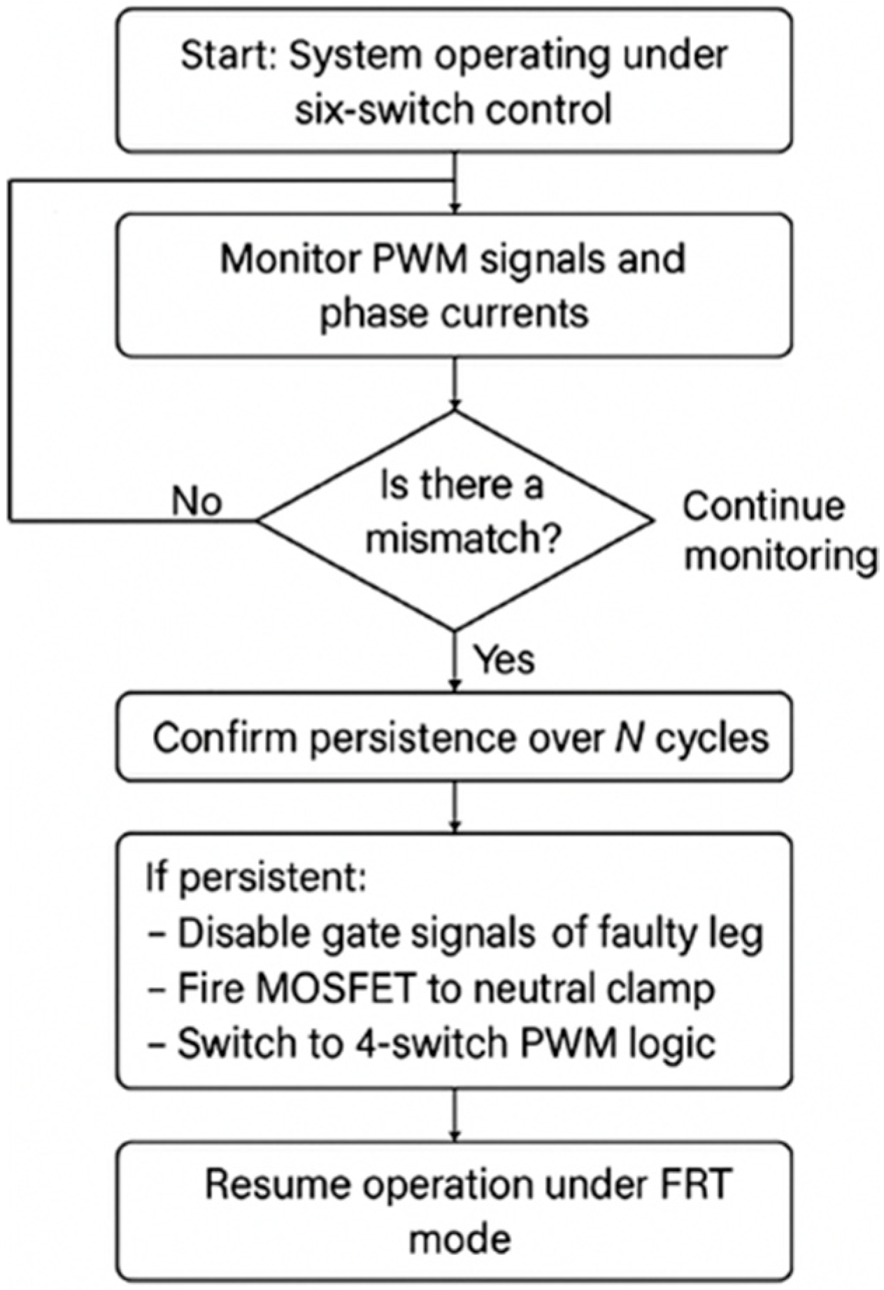
In this work, single open switch faults are considered in each of the three inverter legs (phases A, B, and C). When a fault is detected, the gate signals of the damaged inverter leg are turned off, taking that leg out of operation. To keep the phase current flowing, a MOSFET is then switched on to link the faulty phase with the neutral point of the DC-link. This simple reconfiguration keeps the motor running smoothly without adding any extra hardware, which makes it a very practical choice for electric vehicles where cost and compact design matter.
3.4.2. Gate Drive Failure
Gate-drive failures happen when the small driver circuits that control the inverter switches stop working properly. This can be caused by logic errors, loss of electrical isolation, or small timing faults in the control signals. Even though the switches themselves are not damaged, they can no longer be controlled, which makes the situation almost the same as an open-circuit fault.
In this work, such gate-drive faults are treated as open-switch cases to make detection and correction simpler. That is a reasonable assumption because both faults show almost similar electrical behavior. Using one unified fault model maintains the control logic straightforward and allows faster response with less software complexity.
3.4.3. Partial Inverter Leg Failure
Partial leg faults occur when one of the two switches of an inverter leg has a malfunction, leading to irregular output voltages and distorted phase currents. Although partial faults have less danger than complete leg failures, they may cause:
Severe current imbalance;
Phase-level loss of control;
Increased thermal stress on remaining switches.
Due to their transient and complex nature, partial faults are conservatively modeled as complete open circuit faults in this study.
3.5. Fault Detection Approaches
The performance of any Fault-Ride-Through (FRT) technique is assessed based on how well it can quickly, accurately, and computationally identify inverter problems. A software-based Fault Detection Unit (FDU) is part of the suggested approach. Its purpose is to swiftly and precisely identify open-switch defects in voltage-source inverters, which are utilized in electric vehicle (EV) induction motor drives.
Using logic and comparator structures, the FDU continuously observes the inverter’s operational behavior in order to identify any anomalies that would point to a malfunction. As a result, the method assesses three crucial indicators:
- 1.
Gate signal activity: A healthy inverter leg alternates between ON and OFF states during PWM operation. A switch that remains persistently OFF in spite of command signals may be considered a gate driver fault or a switch failure.
- 2.
Phase current monitoring: The system continuously measures the instantaneous current in each motor phase. A sustained zero or near-zero current in any phase over multiple switching cycles indicates a potential open-circuit condition.
- 3.
PWM command mismatch: The FDU compares the phase current response and the PWM switching command. A fault condition is immediately generated when gating signals are active but the associated current does not flow through.
The technique includes a debounce mechanism that needs the fault condition to last for multiple consecutive switching cycles (usually 3–5) before setting off an alarm in order to improve noise rejection and guarantee detection resilience. This method effectively lowers the number of false positives brought on by brief disruptions or measurement spikes. This approach successfully reduces false positives resulted from transient disturbances or measurement spikes.
The system immediately switched to the fault-handling mode when a fault occurred. There are three primary steps in this mode:
The gate signals to both the upper and lower switches of the faulty inverter leg are disabled to prevent unintended behavior.
A corresponding MOSFET switch (T1, T2, or T3) is activated to reconnect the affected motor phase terminal to the DC-link neutral midpoint.
The control system switches from 6-SI PWM to the 4-SI vector control and modulation scheme described in
Section 4.
The whole process, from detecting the fault to reconfiguring the inverter, takes only a few milliseconds. This fast reaction has the advantage of preventing any interruptions to the motor’s smooth operation. Simple logic blocks and current checks are used in MATLAB/Simulink to evaluate the detection process, which can be linked to real-time automotive controllers.
Because the fault logic is placed directly inside the main control loop and uses the same feedback already available in the system, no extra sensors or backup circuits are needed. This keeps the setup simple, low-cost, and reliable, exactly what modern EV powertrains require.
Figure 2 shows a flowchart that outlines the entire FRT sequence, from healthy operation to fault detection and control adaptation.
4. Proposed Fault-Ride-Through Strategy
Electric vehicle induction motor drives employing a 4-SI require modified vector control strategies to compensate for reduced switching flexibility compared to standard 6-SIs. The four-switch topology, consisting of two legs shared across three phases (typically omitting one switch per phase pair and shorting the neutral through the two-capacitor midpoint), imposes specific constraints on achievable voltage vectors and modulation.
The VC strategy remains based on transforming three-phase currents into the rotating dq reference frame using Clarke–Park transformations, but with adjustments in calculation due to the topology’s missing switch and neutral point clamping.
4.1. Mathematical Equations for VC of a 3-Phase 4-SI
For a 4-SI, the Clarke transformation assumes a virtual neutral point calculated based on capacitor midpoint voltage balancing or by assuming the third phase current as:
Thus, the Clarke transformation becomes:
When the phase (c) current is inferred, only two current sensors are used.
The 4-SI inverter’s mathematical modeling is thought to be functionally equivalent to the 6-SI design shown in the section above. Even though 4-SI has fewer switching devices than 6-SI, its dynamic behavior, control objectives, and analytical expressions all adhere to the same foundations. The same modeling framework and notation system are thus used to construct all ensuing derivations and control formulations. In addition to making theoretical analysis easier, this consistency enables a direct comparison of the two inverter topologies under the same operating circumstances.
4.2. Control System Design
The suggested control approach’s hierarchical structure is made up of two main feedback loops: an outer speed regulation loop and an inner current control loop, both of which are connected by a voltage decoupling mechanism. Under both normal and malfunctioning inverter situations, this integrated architecture guarantees precise control of the induction motor and improves system robustness.
4.2.1. Inner Current Loop
The inner loop regulates the stator currents in the dq reference frame to ensure the accurate generation of both torque and flux. The direct-axis stator current responsible for rotor flux control, is computed based on the desired rotor flux reference and the mutual inductance as in Equation (16).
In this study, the flux reference is selected within the typical operating range of 0.1–1.6 Wb to balance dynamic performance and efficiency.
To enforce current tracking, two identical proportional–integral (PI) controllers are employed, one for each axis (d and q). For controller synthesis, the current dynamics are modeled as a first-order decoupled system. The continuous-time current loop can be approximated as:
Current controller.
The loop has two identical PI controllers, so designing one for the current
is sufficient. The current controller should be designed to overcome the sudden changes in the input, load and system parameters. The current controller, Shown in
Figure 3 processes the reference and measured currents to produce the inverter switching signals that will make sure that the stator currents in the winding follows the reference currents. The current control loop block diagram is shown below:
The decoupled system can be modeled as:
Applying Laplace transform on the first equation of the system above we get the transfer function below:
The transfer function of the PI controller is:
The closed loop transfer function of the system is:
Comparing it with the standard form of a second order system transfer function, we get the gains
and
of the PI controllers as follows:
where
4.2.2. The Outer Speed Loop
The slip angular frequency is calculated using Equation (15).
Speed Controller
The speed controller Shown in
Figure 4 ensures a smooth transient response and that the IM speed always equals the reference speed at steady state. The speed control loop block diagram is shown below:
The speed controller gains for the PI controller were found using an educated guess.
The angular position is calculated by integrating the angular frequency as in Equation (14);
The PI controller is used to generate the torque command for speed control. The PI Controller transfer function is
The plant transfer function is
The transfer function of the speed controller system is
From the given transfer function below
where if
=
, the following can be concluded,
4.2.3. The Voltage Decoupler
The voltage decoupler is placed at the controller output to improve control performance and to mitigate cross-coupling or big and rapid changes in speed, current and flux linkage.
In synchronous rotating reference frame
therefore the ‘complex’ output signals of the voltage decoupler reduces to
4.3. Dynamic Switching Strategy
Upon detection of an open-switch fault in any inverter leg, the proposed fault-tolerant strategy initiates a dynamic reconfiguration process to sustain motor operation. The faulty phase leg is isolated, and its motor terminal is rerouted via a MOSFET to the midpoint of a split DC-link.
During a fault, a sudden interruption of current in the faulty inverter leg can generate damaging transients. In the proposed topology, this problem is mitigated by a MOSFET-based clamping branch connected between the faulty phase terminal and the DC-link midpoint. When a fault is detected, the faulty leg is disabled and the clamping MOSFET immediately provides a low-impedance path for the phase current, maintaining continuity and preventing overvoltage. The split DC-link capacitors serve as temporary energy buffers, absorbing the transient energy until the system stabilizes and transitions to fault-tolerant operation.
The reconfiguration procedure is started by the Fault Detection Unit (FDU), which also carries out the subsequent series of actions:
To avoid unexpected commutation or switching irregularities, it turns off the impacted inverter leg’s upper and lower switches.
It connects the malfunctioning motor terminal to the virtual neutral point by turning on the matching MOSFET (T1, T2, or T3).
The system is switched to the 4-SI operating mode, which maintains the defective leg at a fixed voltage.
This configuration maintains a continuous current path across all three motor phases. This is still valid even if the independent voltage control on the faulted phase is no longer available. The reconfiguration logic is computationally efficient and is completed within a few milliseconds. Therefore, it is highly suitable for real-time, automotive-grade traction applications.
The complete detection to reconfiguration sequence is achieved in less than 5 ms, which is significantly faster than a single electrical cycle at 50 Hz (20 ms). This fast response effectively dominates any sustained overcurrent, and hence ensuring continuous and safe motor operation.
4.4. Reconfigured PWM Scheme for 4-Switch Inverter
In its healthy mode, the inverter employs standard PWM to produce optimal voltage vectors. Nevertheless, when a leg is disabled, the available switching states are reduced, and conventional PWM becomes unworkable.
To address this, a modified PWM strategy is adopted:
Voltage reference vectors are reconstructed in a reduced two-phase space (dq plane excluding the faulty phase).
The inverse Park transformation is applied to generate modulation signals for the remaining two active legs only.
The clamped phase terminal is fixed to the DC-link midpoint, acting as a passive return path.
Key objectives of this reconfigured modulation include:
Minimizing torque ripple.
Preserving average voltage magnitude.
Preventing capacitor voltage imbalance in the split DC-link.
5. Simulation Results
To validate the effectiveness of the proposed fault-ride-through (FRT) control strategy, the EV induction motor drive system is implemented using MATLAB/POWERSIM version 2023b. Three simulation scenarios were conducted to evaluate: healthy operation during the 6-SI feeding the vector-controlled EV induction motor drive system, fault occurrence in one of the 6-SI and reconfiguration to 4-SI operation, and post-fault degraded mode. Key performance metrics such as torque ripple, speed tracking, current asymmetry, and transition time were analyzed.
Figure 5 shows the overall control system.
Test Cases and Observations
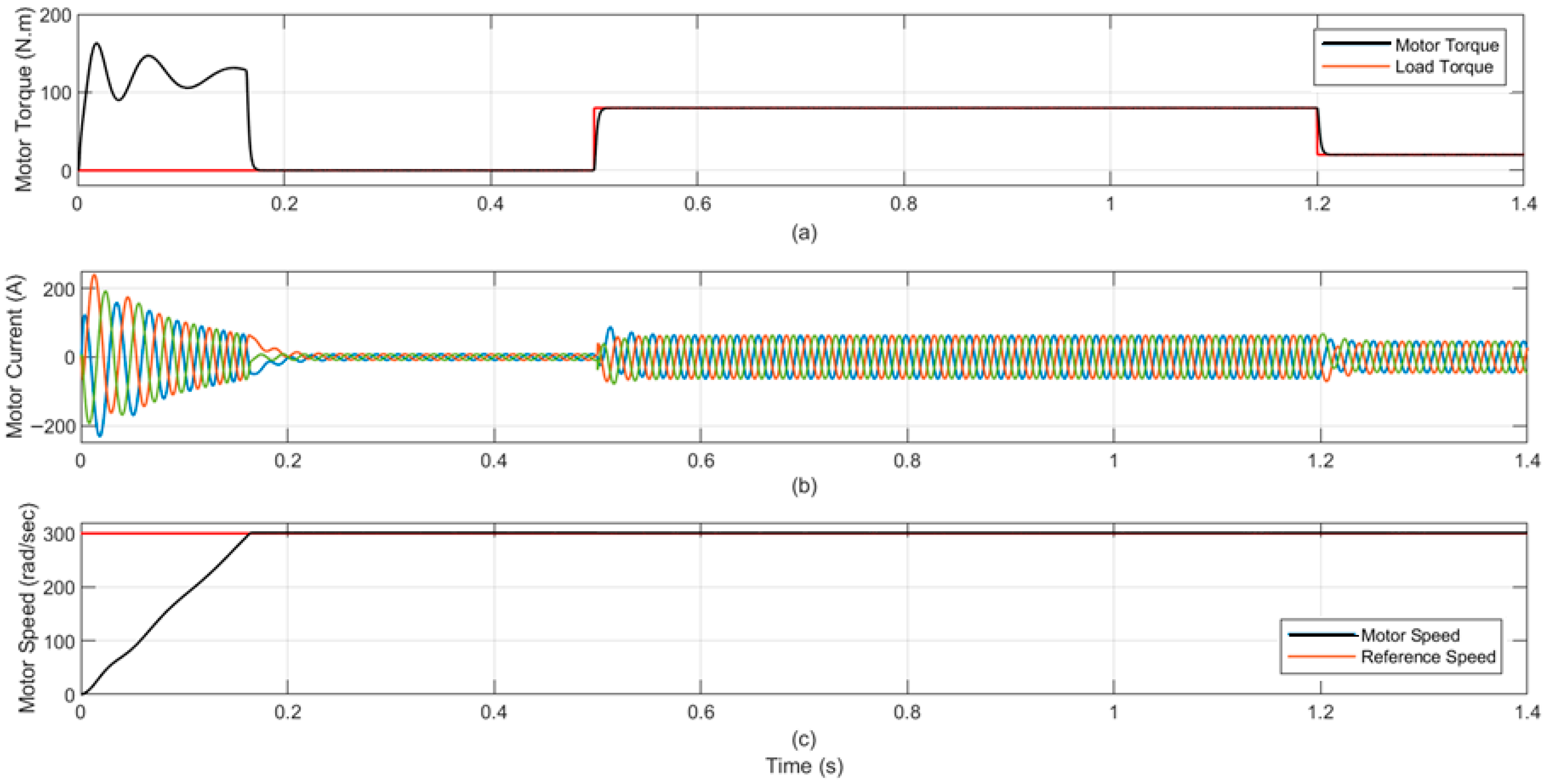
In the standard operation, our system employs VC to precisely manage the 6-SI. This allows the motor to rapidly achieve its reference speed of 300 rad/s, settling exactly on target with a “dead-beat” response and virtually no overshoot. Throughout all dynamics in this scenario, the electromagnetic torque and stator currents consistently remained highly stable, exhibiting minimal ripple. We conducted two distinct evaluations in this scenario. Test 1, shown in
Figure 6, examined the system’s performance during step changes in load torque. At t = 0.5 s, the load torque abruptly increased from 0 N.m to 80 N.m. Then, at t = 1.2 s, it stepped down to 20 N.m. Test 2, detailed in
Figure 7, assessed how well the proposed system handled speed changes. At t = 1 s, the speed drops from 300 rad/s to 100 rad/s. Then, at t = 1.5 s, it increases to 200 rad/s. Both tests consistently displayed smooth current, torque, and speed profiles, confirming precise torque production and a swift speed response throughout.
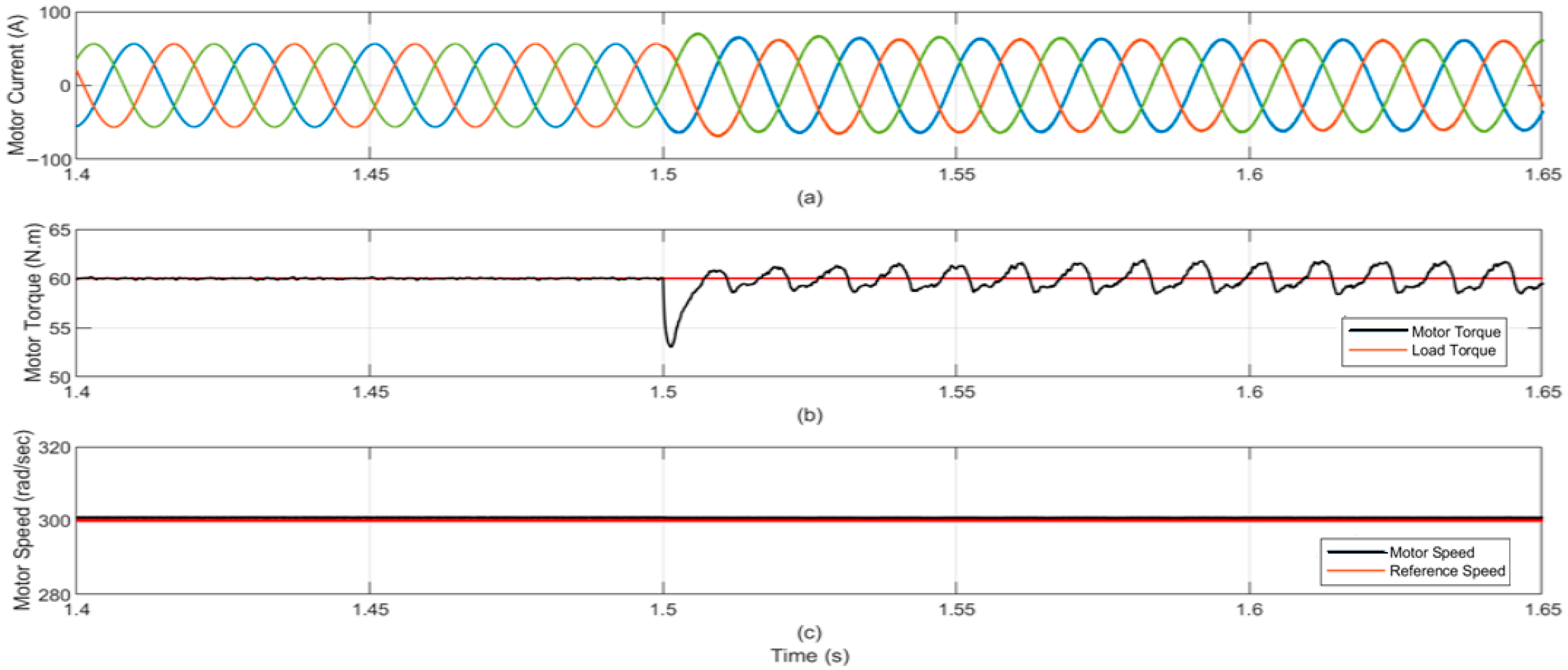
At t = 1.5 s, a permanent open-switch fault is injected into the lower switch of Phase A. The fault detection unit identifies the anomaly and triggers reconfiguration. The control scheme disables the faulty leg and activates the associated thyristor, clamping the motor terminal to the DC-link midpoint. During the transition, the proposed system experiences a brief, minor ripple in its torque output. We also observed a negligible speed reduction, approximately 1.2 rad/s, which the system rapidly adjusts as it re-stabilizes.
Figure 8 provides a visual representation of the EV induction motor’s response during this critical handover, clearly depicting the moment the control switches from the 6-SI to the 4-SI configuration.
The system’s recovery performance was evaluated by measuring fault detection latency, reconfiguration delay, and the settling times of both the current and speed control loops. For double-switch fault scenarios, the combined detection and reconfiguration duration was approximately 6 ms, while the current loop settled within 30–50 ms and the speed loop within 150–220 ms. These results demonstrate rapid post-fault stabilization and effective control recovery.
Following reconfiguration, the system resumes operation using only two active legs. The adapted VC and custom PWM scheme maintain motor functionality.
Key observations include:
Final steady-state speed: ~301.2 rpm (≈0.4% increase from reference speed).
Torque ripple: noticeable increase (≈1.9% more from 6-SI).
Current waveforms showed temporary asymmetry during brief transitions but quickly returned to normal. Post-transition, the total harmonic distortion (THD) increased by about 2.9% to 4.2%, which remains within the acceptable limits of the IEEE 519 harmonic standard.
No stalling or shutdown observed.
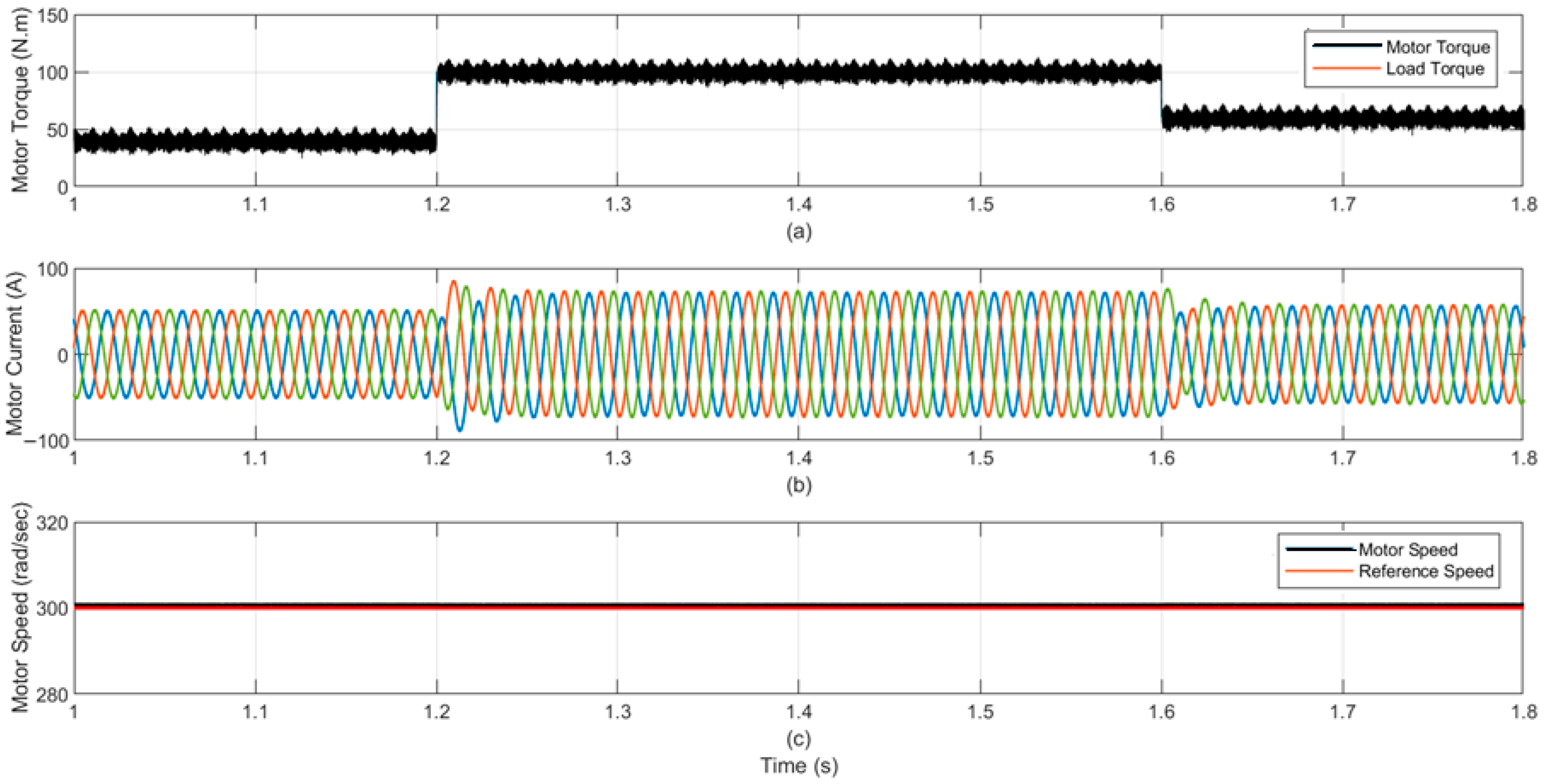
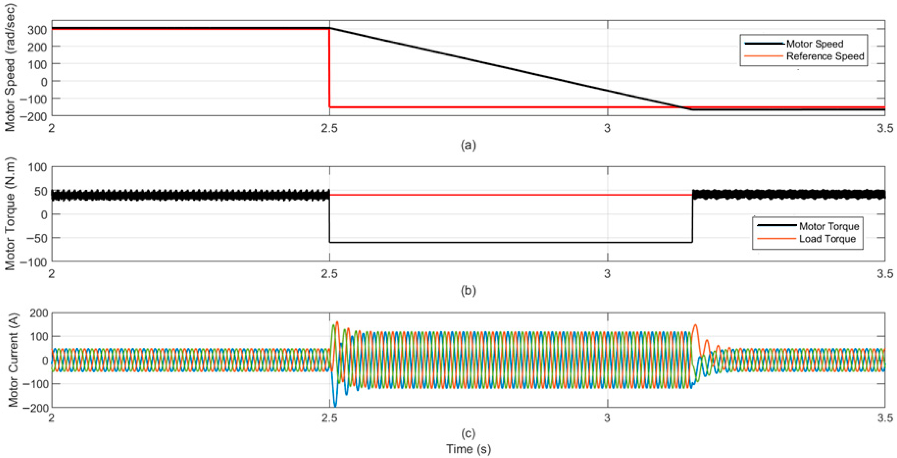
To thoroughly evaluate the proposed system in its 4-SI configuration, which utilizes adapted VC and custom PWM, we performed three specific tests: Test 1 challenged the system with step changes in the load torque, by increasing and decreasing the load torque. Test 2 assessed its response to step changes in motor speed, stepping up and down, and Test 3 examined its performance during a complete speed reversal. In Test 1, shown in
Figure 8, at t = 1.2 s, the load torque increased from 40 N.m to 100 N.m. At t = 1.6 s, the load torque steps down from 100 N.m to 60 N.m. In Test 2, given in
Figure 9, at t = 1 s, the speed steps up from 100 rad/s to 300 rad/s. At t = 2.5 s, the speed steps down from 300 rad/s to 50 rad/s. In Test 3, illustrated in
Figure 10, the speed is reversed at t = 2.5 s from 300 rad/s to −200 rad/s.
Figure 9,
Figure 10 and
Figure 11 display the post-fault torque, speed, and current profiles, affirming the effectiveness of the fault-tolerant strategy.
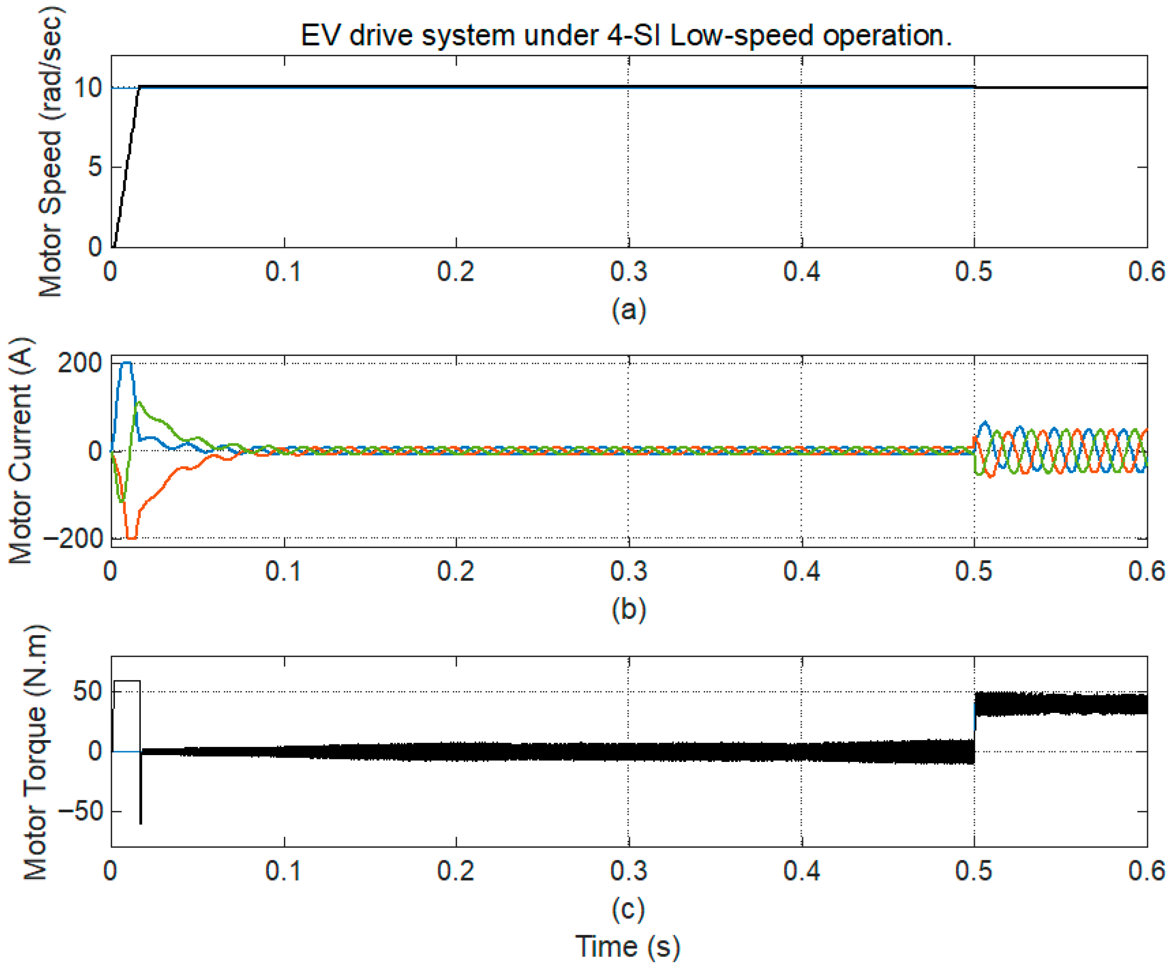
Figure 12 shows that the proposed system provides excellent performance even during post-fault (4-SI) low-speed operation.
Table 4 summarizes the approximate speed-response metrics for the three operating cases of the proposed system. The results show that the proposed method achieves a fast rise time and almost zero overshoot in the healthy mode, while maintaining acceptable dynamics during the fault transition and post-fault operation with settling times of about 150–220 ms and a steady-state error less than 0.5%.
Finally, the proposed technique is compared with the technique used in [
25]. The proposed controller demonstrates noticeably faster transient behavior and lower steady-state deviation, confirming its effectiveness in both normal and fault-tolerant conditions. The detailed comparison between the speed and response performance metrics (% overshoot, rise time, settling time, and steady-state error) for the 4-SI application of both control methods are presented in
Table 5.
6. Discussion
The proposed Fault-Ride-Through (FRT) strategy has been validated through comprehensive dynamic simulations under a variety of test conditions, including step changes in load torque, speed variations, and full reversals as given in
Table 6. The results demonstrate that the system ensures continuous operation and keeps performance metrics even after switching from 6-SI to 4-SI topology.
The proposed FRT strategy is suitable for both low and mid-power EV platforms, in which cost, weight, and design simplicity are critical issues. Among its applications are electric rickshaws, e-bikes, and two-wheeled scooters. Compact induction motor drives without extra hardware are used in these cars. As a result, the software-based reconfiguration method is more economical and useful.
Compact EVs and vans can also use the same inverter architecture and control system. This makes it possible for the car to continue operating normally even in the event of an inverter malfunction. The suggested method’s scalability allows it to be used with a variety of EV traction system types, from tiny single-motor drives to more extensive distributed systems.
The system can be switched to 4-SI operating mode in roughly 5 milliseconds when a defect arises, which can be symbolized by a permanent open-switch failure in one of the inverter legs. Therefore, even a small disruption can maintain the drive’s capacity to produce torque. Additionally, the electromagnetic torque stays below permissible operating limits despite showing a minor increase in ripple (about 1.9%) as compared to the healthy condition. An essential requirement for EV applications, these results confirm that the updated vector control and PWM system successfully maintains steady torque performance and guarantees continuous operation.
Following the failure event, there is little steady-state inaccuracy in the motor speed’s adherence to the reference command. A maximum observed deviation of around 0.4% is not exceeded, which is consistent with high-performance control standards. It is observed that the degree of precision is kept within allowable bounds even when speed is reversed and load disturbances change. The drive’s steady performance under these changing circumstances demonstrates the effectiveness of the control reconfiguration and emphasizes how well the suggested PWM approach handles the absence of redundancy.
The irregular transient currents observed during fault reconfiguration settle quickly and restore normal operation within a short time. Total harmonic distortion (THD) increases from nominal levels to approximately 4.2%, and hence remains within the limits of IEEE 519 compliance with adverse impact on system stability. Furthermore, the drive successfully avoids shutdown across all test scenarios, which confirms the robustness and effective fault suppression of the proposed strategy. In addition, it is observed that the peak transient current remains around 1.15 p.u., which means that the semiconductor devices are not exposed to over-stress during the fault and recovery phases.
The suggested solution exhibits better real-time adaptability than current methods in the literature, which frequently suffer from incomplete reconfiguration, delayed fault detection, or inadequate post-fault control retuning [
6,
15,
16]. It also uses standard components and software-level intelligence to maintain seamless performance, which improves the feasibility of implementation for embedded EV traction platforms in contrast to previous studies that rely on passive fault masking techniques or hardware redundancy [
3,
7,
19].
To evaluate the robustness of the PI-based control under faulted situations, ±10% changes in stator resistance (Rs) and inductance (Ls) are introduced. With a motor speed variance of less than 2%, the system demonstrates effective parameter tolerance and continues to operate steadily. The current study is on a computationally effective, affordable implementation appropriate for embedded EV drive systems, even if sophisticated nonlinear controllers could further enhance disturbance rejection.
However, it is important to recognize that there are some performance trade-offs. Higher copper losses and localized thermal stress are the results of the intrinsic asymmetry introduced by the 4-SI configuration in the voltage vectors and current conduction channels. In comparison to the healthy 6-SI mode, the overall efficiency degradation is measured at roughly 5–7%, which is consistent with the numbers for FSTPI-based systems that have been published in earlier research [
11,
12]. Given the significant advantage of maintaining continuous drive operation under faulty situations, this moderate efficiency penalty is considered acceptable for the majority of EV applications, especially those aimed at cost-sensitive markets.
Furthermore, there are still certain restrictions on the reliability of problem detection and the distribution of thermal stress in noisy working environments. The predictable signal behavior assumed by the existing detection technique might not apply to every situation in the actual world.
Future research should look into sensorless and AI-enhanced fault classification methods to improve system robustness in order to overcome these issues. Furthermore, to assess controller timing and performance under real-time limitations, hardware-in-the-loop (HIL) testing is advised. The implementation of intelligent inverters enhanced with artificial intelligence and cybersecurity capabilities is a viable option for future study, given the increasing integration of distributed energy resources and the changing operational threat scenario. In addition to offering a platform for integrating sophisticated diagnostics and control intelligence at the network edge, such systems can improve grid resilience and adaptability [
26].
In conclusion, the design objectives of the proposed FRT technique are effectively met. Quick fault isolation, dynamic inverter reconfiguration, and software-based control adaptation are some of these objectives. The system’s potential as a practical and expandable solution for EV powertrains of the future is validated under a range of dynamic circumstances. The approach balances cost, control performance, and reliability, removing the need for hardware redundancy while ensuring adherence to industry-standard performance benchmarks.
7. Conclusions
In order to ensure continuous operation in electric vehicle (EV) applications, this paper suggests a fault-tolerant control method for inverter-fed induction motor drives. The suggested system identifies open-switch defects in real time, dynamically reconfigures the inverter topology to a reduced 4-SI mode, and adjusts the vector control (VC) and pulse-width modulation (PWM) schemes accordingly, all without the need for extra sensing components or hardware redundancy.
Simulation results in various circumstances, such as torque steps, speed changes, and complete reversals, validate the proposed strategy.
The system maintained precise speed control and torque generation within reasonable bounds during post-fault operation. Fault detection and inverter reconfiguration took less than five milliseconds.
These results show that sophisticated software-based adaptation with little need for extra hardware can provide robust fault ride-through in electric vehicle drives.
The suggested technique offers an affordable and scalable substitute for traditional methods that depend on redundant hardware. This makes it appropriate for embedded control systems. These results support the approach as a feasible and useful candidate for use in traction applications of automotive grade.
Future work aims to extend this framework to multiphase traction systems, supported by hardware-in-the-loop (HIL) testing and experimental validation using a 3 kW prototype currently, that is under development. Additionally, advanced fault classification algorithms will be integrated to further improve system reliability and diagnostic accuracy.
