Abstract
This paper presents a coordinated control strategy for an electro-hydraulic composite braking system in in-wheel motor electric vehicles to enhance regenerative energy recovery and braking safety. A novel hydraulic control unit (HCU) without a pressure-reducing valve is designed to simplify structure and maximize energy utilization. Based on the ideal braking force distribution, a force allocation strategy coordinates motor and hydraulic braking across modes, ensuring motor torque can compensate total braking torque when wheel lock occurs. An anti-lock braking (ABS) strategy relying solely on motor torque adjustment is proposed, keeping hydraulic torque constant while rapidly stabilizing slip within 13–17%, thereby avoiding interference between hydraulic and motor braking. A joint Simulink–AMESim–CarSim platform evaluates the strategy under varying conditions, and real-vehicle tests in regenerative mode confirm feasibility and smooth switching. Results show the proposed approach achieves target braking intensity, improves energy recovery, reduces torque oscillations and valve actions, and maintains stability. The study offers a practical solution for integrating regenerative braking and ABS in in-wheel motor EVs, with potential for hardware-in-the-loop validation and advanced stability control applications.
1. Introduction
Energy regeneration is an important approach to extend the driving range of electric vehicles (EVs). However, with the addition of motor braking force, coordinating the traditional hydraulic braking system and the anti-lock braking system (ABS) to simultaneously ensure vehicle stability and maximize energy regeneration remains a challenge [1]. Therefore, improving the coordination of motor braking force and hydraulic braking force in electro-hydraulic composite braking systems is of considerable significance.
To achieve rapid adjustment and precise response of hydraulic braking force, Bosch’s iBooster replaces the conventional vacuum booster with a motor and gear reducer [2]. In [3], a self-developed motor booster is adopted to replace the vacuum booster, which improves the realization of the ideal braking force distribution curve (curve I) and enhances braking energy recovery efficiency. Reference utilizes a battery–supercapacitor hybrid instead of a traditional chemical battery to build an efficient regenerative braking system [4]. An electronic friction brake system with an electronic wedge brake at the front wheels and a hydraulic brake at the rear wheels for a parallel hybrid electric vehicle (HEV) is presented in [5], eliminating the need for a separate pedal simulator or fail-safe device.
Conditions for regenerative braking, energy flow during the process, and implementation methods are analyzed in [6]. For pressure estimation [7], describes a real-time integrated time-series model using multivariate deep recurrent neural networks with long short-term memory (LSTM). The anti-lock conditions and the slip ratios of front and rear wheels for braking force distribution are described in [8]. A cyber-physical system (CPS)-based framework for co-design optimization of plant and controller parameters for automated EVs is proposed in [9].Trajectory control for autonomous EVs with in-wheel motors (IWMs) based on a potential field approach is studied in [10,11]. On the basis of analyzing the structure and principle of the hydraulic braking system and the regenerative braking system (RBS), a feasible braking scheme and simulation modeling method are proposed in [12].
Researchers have also made extensive efforts to enhance the energy recovery efficiency of electro-hydraulic composite braking systems. An MPC-based RBS is presented in [13], while Reference [14] prioritizes motor braking force recovery. In [15], the electric motor cooperates with the hydraulic system to apply ideal braking torque to the rear wheels of a three-wheel recreational EV. A braking strategy based on ideal braking force distribution is proposed for a small front-wheel-drive (FWD) EV in [16]. On the basis of half-shaft torque estimation [17], proposes two new regenerative braking control algorithms to improve both directional stability and recovery efficiency. In [18,19], a cooperative regenerative braking control algorithm is introduced that avoids wheel lock by performing regenerative braking and friction braking on the front wheels, while the rear wheels use friction braking only.
To better coordinate hydraulic and motor braking forces [20], analyzes the relationship between the hydraulic control unit (HCU) and the brake pedal simulator. In [21], an optimal distribution coefficient response surface is established to solve braking force allocation across different modes. A torque coordination strategy for electro-hydraulic composite braking during mode switching based on braking intention is described in [22]. A hybrid ABS control strategy is proposed in [23], which identifies the road surface condition and determines the optimal wheel slip ratio accordingly.
In addition to these methods, mismatched response speeds of the motor and the hydraulic unit limit coordination performance. Reference [24] mitigates braking force fluctuations through compensation control and simplifies the motor dynamics as a first-order inertial system. Few studies address regenerative braking under coasting conditions. In [25], a coasting control strategy based on driver feeling is proposed. A regenerative braking strategy that considers driver intention during coasting is introduced in [26]. Reference [27] presents an energy recovery mode that enables regenerative braking in all driving situations.
The aforementioned methods for improving electro-hydraulic composite braking systems primarily focus on actuators (e.g., motors and boosters) or control algorithms, with limited attention given to redesigning the hydraulic control unit. Moreover, during the electro-hydraulic composite braking process, ABS control is conventionally achieved by coordinating both motor and hydraulic torques [28]. In this paper, a novel HCU without a pressure-reducing valve and an ABS strategy based solely on motor torque regulation are proposed for in-wheel motor (IWM) EVs. The objective is to maximize the use of motor braking torque to recover as much energy as possible while ensuring braking stability.
The main contributions of this work are threefold: (1) the design of a novel HCU without a pressure-reducing valve, which improves braking energy recovery and extends driving range; (2) the proposal of a braking energy recovery strategy based on ideal braking force distribution to allocate braking force according to the braking mode; and (3) the development of an ABS strategy based purely on motor torque adjustment, which regulates wheel slip only through motor torque control during wheel lock.
The remainder of this paper is organized as follows. Section 2 presents the overall structure of the electro-hydraulic composite braking system and the novel HCU. Section 3 describes the braking energy recovery strategy based on curve I and the ABS control strategy using pure motor torque adjustment. In Section 4, the control strategies are validated under various simulation conditions. Section 5 reports tests on the hydraulic control system and real vehicle experiments in pure regenerative braking mode. Finally, Section 6 concludes the paper.
2. Electro-Hydraulic Composite Braking System Design
2.1. The Overall Layout Scheme
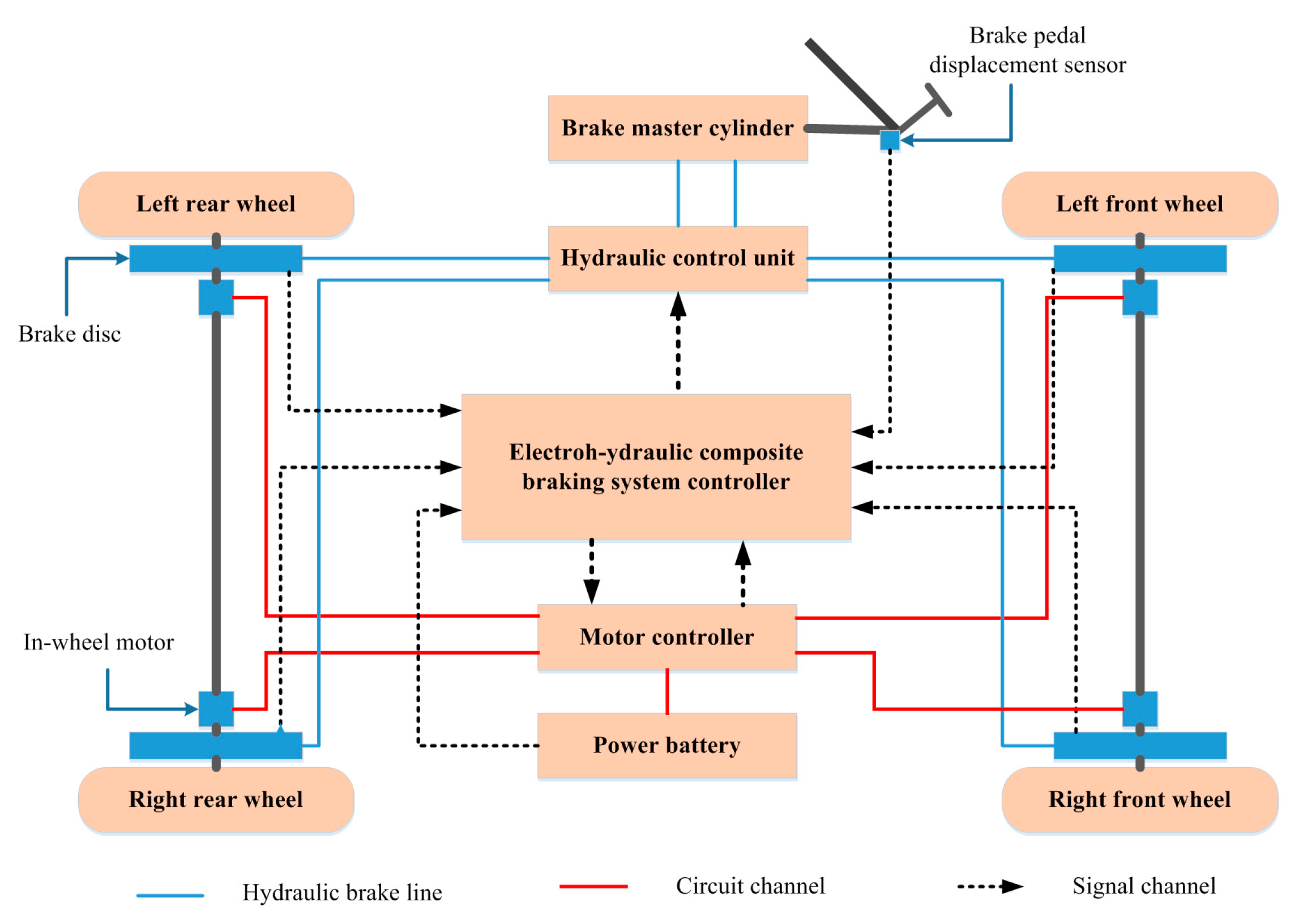
The electro-hydraulic composite brake system mainly includes an electro-hydraulic composite braking system controller, HCU, motor controller, power battery, disc brake, hub motor, brake master cylinder, brake pedal and the related sensors, as shown in Figure 1.
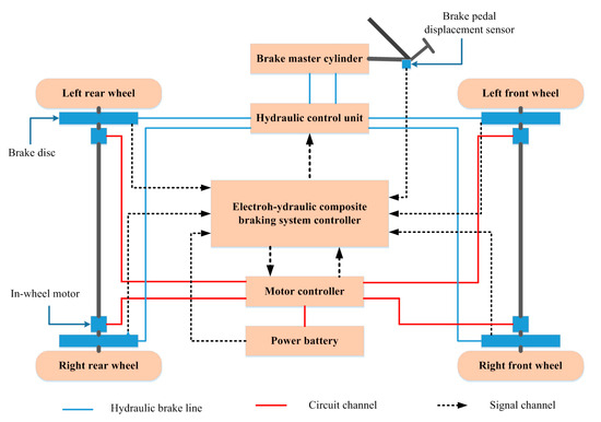
Figure 1.
Structure of the electro-hydraulic composite braking system.
The operating principle of the system is as follows: the brake pedal displacement sensor collects the driver’s brake pedal displacement information and then transmits the signal to the electro-hydraulic composite braking system controller. The controller completes the distribution of the front and rear axle braking torque, as well as the motor braking torque and hydraulic braking torque, through the corresponding control strategy. The motor controller can directly receive the controller area network (CAN) message from the brake controller to control the braking torque of the motor. The brake controller controls the hydraulic braking torque by receiving the feedback signals from the pressure sensor and the relevant solenoid valve of the HCU. In addition, the brake controller determines the slip ratio by receiving the wheel speed signal and the vehicle speed signal. When the slip rate exceeds the threshold value, the ABS control is completed by adjusting the motor torque.
2.2. The Novel Hydraulic Control Unit
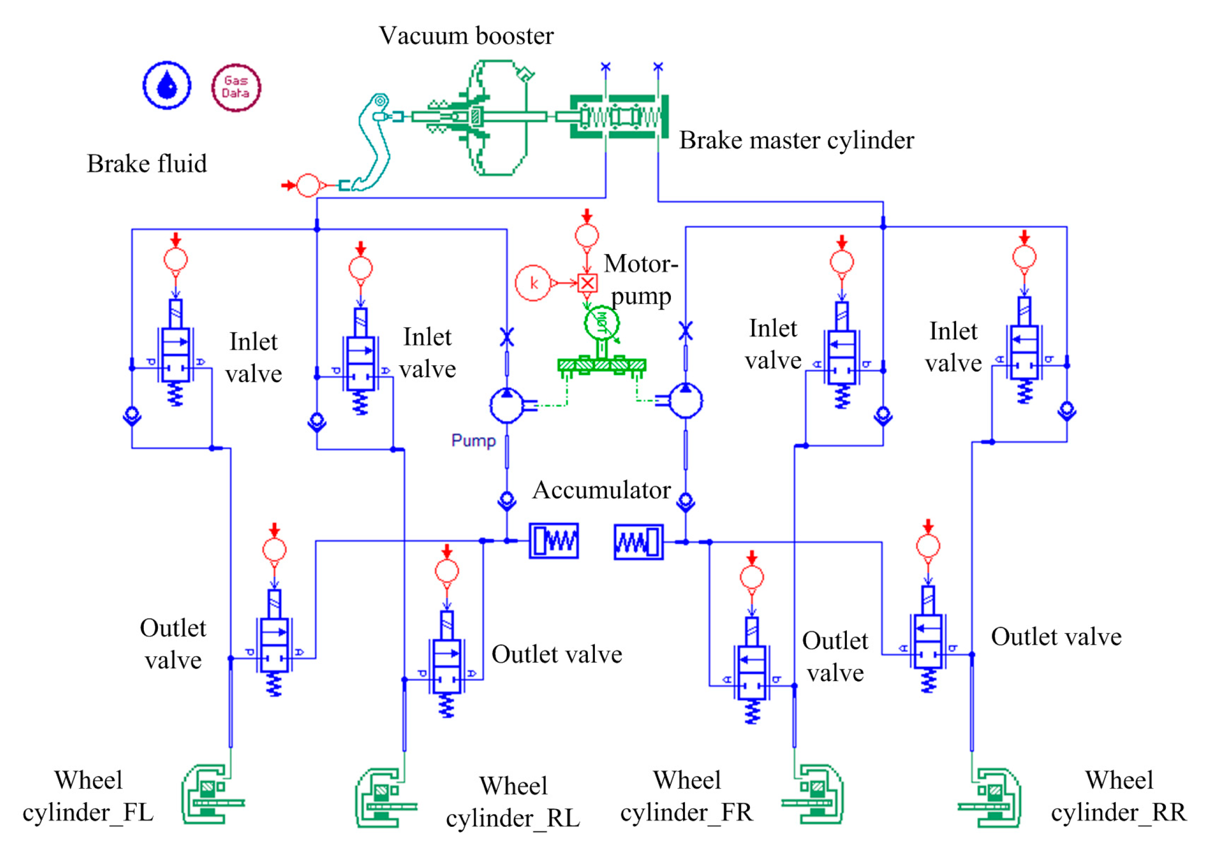
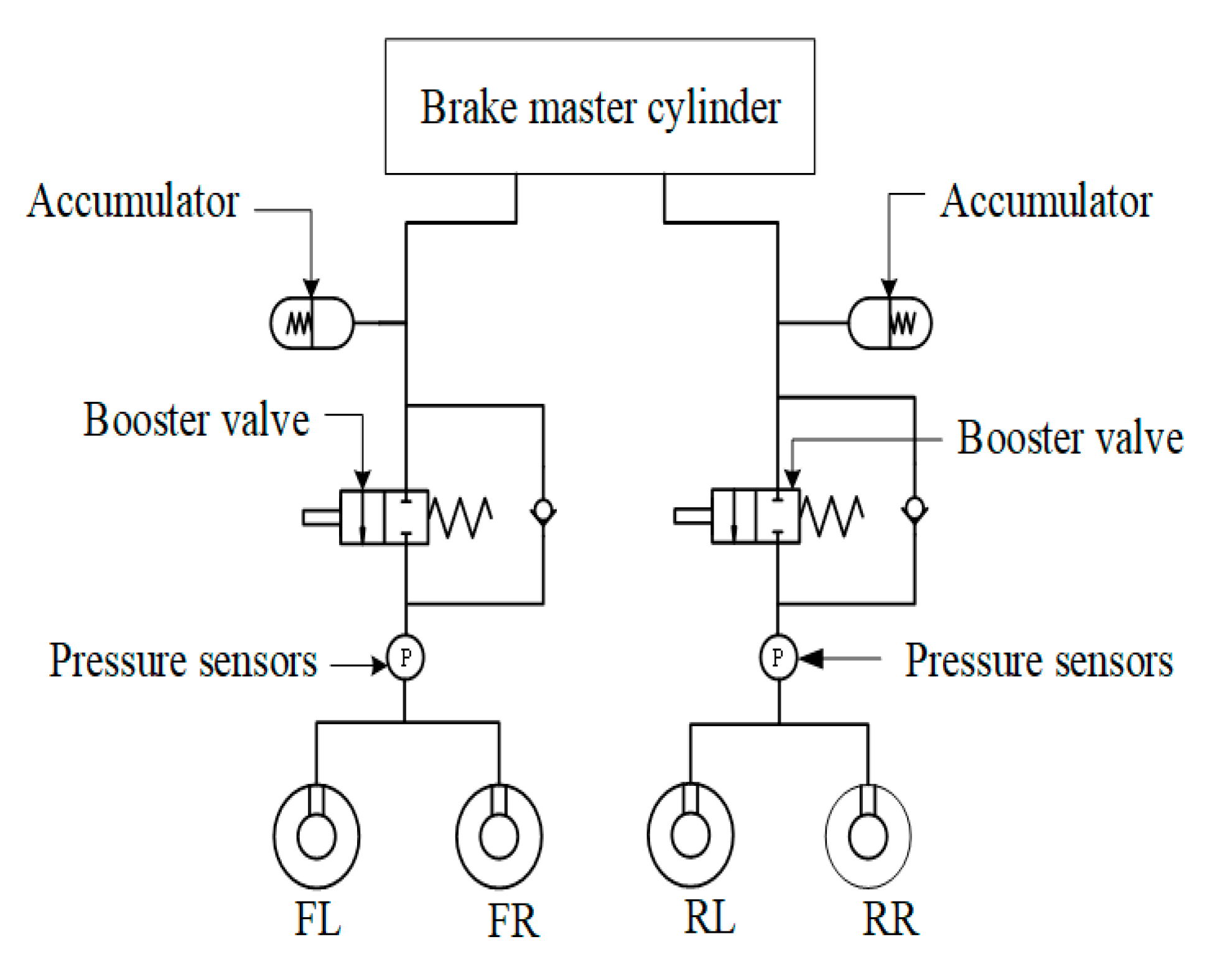
To improve the braking energy recovery rate and extend the driving range of the IWM EV, a new HCU without a pressure-reducing valve is designed on the basis of a traditional HCU (Figure 2). The unit consists of two booster valves, two pressure sensors and two high-pressure accumulators, as shown in Figure 3.
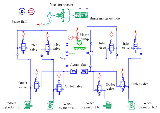
Figure 2.
Structure of the traditional hydraulic control unit.
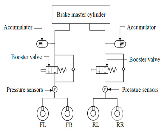
Figure 3.
Structure of the novel hydraulic control unit.
The working principle of this structure is as follows: During pure motor regenerative braking mode, the pressure increasing valve remains closed, and the brake fluid flows to the high-pressure accumulator, ensuring that the hydraulic braking torque is zero. During electro-hydraulic hybrid braking mode, the pressure increasing valve opens, allowing brake fluid to enter the brake wheel cylinder to provide a base hydraulic braking torque, while the motor braking torque delivers the remaining required braking torque. The hydraulic braking torque is calculated based on the pressure detected by a sensor in the brake wheel cylinder, thereby achieving feedback control of the hydraulic braking torque. During braking, if the motor braking torque is insufficient or fails, the pressure increasing valve opens, enabling the oil in the high-pressure accumulator to flow into the brake wheel cylinder, thereby rapidly supplementing the hydraulic braking torque and ensuring redundancy in the electro-hydraulic braking system. Throughout the braking process, the hydraulic braking torque is not actively reduced. When wheel lock-up occurs, the motor torque is controlled to adjust the total braking torque applied to the wheel, thereby modifying the wheel’s state.
The proposed HCU offers significant advantages over the conventional system through simplified structure and enhanced control flexibility. Unlike the traditional HCU, which relies on four inlet and four outlet valves along with multiple accumulators and pumps to regulate pressure, the new design employs only two pressure-increasing valves, two pressure sensors, and two high-pressure accumulators. This structural simplification not only reduces component count and cost, but also diminishes hysteresis and nonlinearity in braking pressure control. Furthermore, the proposed system introduces motor-regenerative braking for antilock control, allowing hydraulic braking to provide only the base torque while the motor adjusts the remaining torque dynamically. This enables more precise slip ratio regulation with smoother transitions and improved energy recovery. Additionally, the new HCU offers functional redundancy: in case of motor torque deficiency or failure, hydraulic torque can be rapidly supplemented via the high-pressure accumulators. These improvements collectively enhance the responsiveness, reliability, and energy efficiency of the electro-hydraulic braking system.
This section selects the hydraulic library, mechanical library, and signal library in AMESim to build a new hydraulic control model. When the driver applies the brakes, the pedal force acts on the brake master cylinder through the vacuum booster. The brake master cylinder converts the braking force into hydraulic oil pressure, which flows to the normally closed solenoid valve. When in pure electric braking mode, the booster valve is closed, and hydraulic oil flows into the high-pressure accumulator. When switching to hydraulic braking mode or in the electro-hydraulic composite braking mode, the booster valve opens, allowing the hydraulic oil to enter the brake wheel cylinder. When the hydraulic braking force reaches the target hydraulic braking force, the booster valve is closed.
The AMESim model developed in this study is based on a tandem master cylinder, which is the most commonly employed configuration in modern vehicles, as illustrated in Figure 4. Develop physical and mathematical models for the brake master cylinder and solenoid valve in the hydraulic control system.

Figure 4.
Brake Master Cylinder Model.
When there is a gap, the motion equation of the rear cylinder piston is:
where: is the mass of the rear cylinder piston, is the displacement of the rear cylinder piston, is the braking force acting on the master cylinder, is the pressure of the brake fluid in the rear cylinder, is the spring force when there is piston clearance, is the damping force when there is piston clearance.
The motion equation of the front cylinder piston is:
where: is the mass of the front cylinder piston, is the displacement of the front cylinder piston, is the spring force in the front cylinder, and is the pressure of the braking fluid in the front cylinder.
The spring force and the damping force when piston clearance exists are denoted as and , respectively
where is the spring stiffness when clearance is present, is the spring compression under the clearance condition, and is the damping coefficient with clearance.
During the braking process, the brake fluid flow rates at the front chamber outlet and the rear chamber outlet are given by:
where and are the cross-sectional areas of the front and rear brake pistons, respectively. In the absence of clearance between the pistons, only the spring stiffness and damping coefficient change. Accordingly, the equations of motion for the pistons under this no-clearance condition can be derived following the same principle.
The solenoid valve is a critical component of the hydraulic control unit (HCU), regulating the brake fluid flow from the master cylinder to the wheel cylinder via the opening and closing of the pressure-increasing valve. The AMESim model developed in this study is based on a two-position, two-way solenoid valve, whose response characteristics directly influence the control precision of the hydraulic braking force. This section analyzes the solenoid valve from two key aspects: its force dynamics and flow characteristics. The solenoid valve, as an important component of the hydraulic control unit, is mainly affected by electromagnetic force, spring force, and hydraulic pressure during the opening and closing process. Its motion equation is:
Among these, represents the spool mass, denotes the electromagnetic force acting on the spool, indicates the spring force applied to the spool, and refers to the hydraulic force exerted on the spool. The frictional force and other forces acting on the valve core during its movement are relatively smaller compared to the previous three items and will not be considered in the study.
The electromagnetic force , which serves as the sole active force responsible for opening and closing the valve spool, is directly adjustable by controlling the magnitude of the coil current. The force generated by the electromagnetic coil upon energization is given by:
where is the magnetic flux, is the magnetic flux density, and is the perpendicular cross-sectional area. The magnetic flux is defined by the following equation:
where I is the current, N is the number of coil turns, and is the total magnetic reluctance of the circuit. The resulting magnetomotive force is governed by the following equation:
where and are the inherent magnetic reluctance of the spool and the reluctance of the air gap in the magnetic circuit, respectively. The total magnetic reluctance is calculated as follows:
where is the length of the magnetic path along the field direction. The total hydraulic force, , acting on the solenoid valve spool comprises two primary components: the hydraulic pressure force, , resulting from the pressure differential across the spool, and the hydrodynamic flow force, , arising from the momentum change of the hydraulic oil.
The hydraulic pressure force is calculated as the product of the pressure difference and the corresponding cross-sectional area of the spool, expressed as:
The flow force comprises steady-state and transient components. The steady-state force is defined as the force resulting from the momentum change of the oil and is given by:
Transient hydrodynamics refers to the forces generated due to changes in the velocity of hydraulic oil, and its calculation formula is:
The solenoid valve regulates the flow rate through the valve orifice by adjusting the position of its spool. When the spherical head of the spool is seated against the lower orifice, the valve is in the closed state, preventing hydraulic oil from flowing to the outlet. Conversely, when the spool head retracts to the upper position, the valve opens, allowing hydraulic oil to pass through the annular gap between the tapered seat and the spherical head toward the outlet. The flow rate Q of the hydraulic oil passing through the orifice is given by:
The flow rate is governed by the orifice opening, x, and the corresponding flow area . Under a constant pressure difference, the flow is initially constrained by the size of the annular gap between the spherical head and the tapered seat. As the orifice opening increases, the flow area eventually exceeds the cross-sectional area of the orifice itself, . Beyond this point, the flow rate becomes limited by the orifice area .
When flow restriction is dominated by the gap between the spherical head and the tapered seat, the effective flow area is calculated as follows:
When the throttling of hydraulic oil is governed by the cross-sectional area of the orifice, the effective flow area corresponds to the orifice’s geometric cross-section. Under this condition, the flow rate is primarily determined by the physical dimensions of the orifice itself.
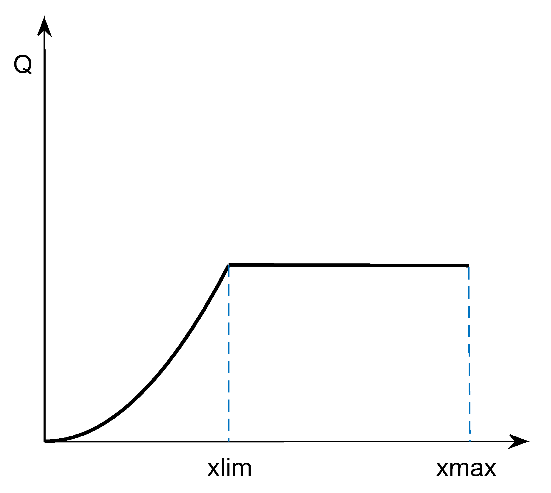
By combining Equations (15)–(17), the relationship between the hydraulic oil flow rate through the orifice and the orifice opening, x, can be determined as illustrated in Figure 5. The flow rate Q increases with the opening x when x < , where represents the critical opening beyond which the orifice area becomes the limiting factor. Once x exceeds , the flow rate Q remains constant and becomes independent of further increases in x.
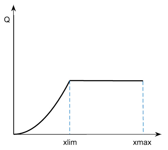
Figure 5.
Flow rate of hydraulic oil as a function of the orifice opening.
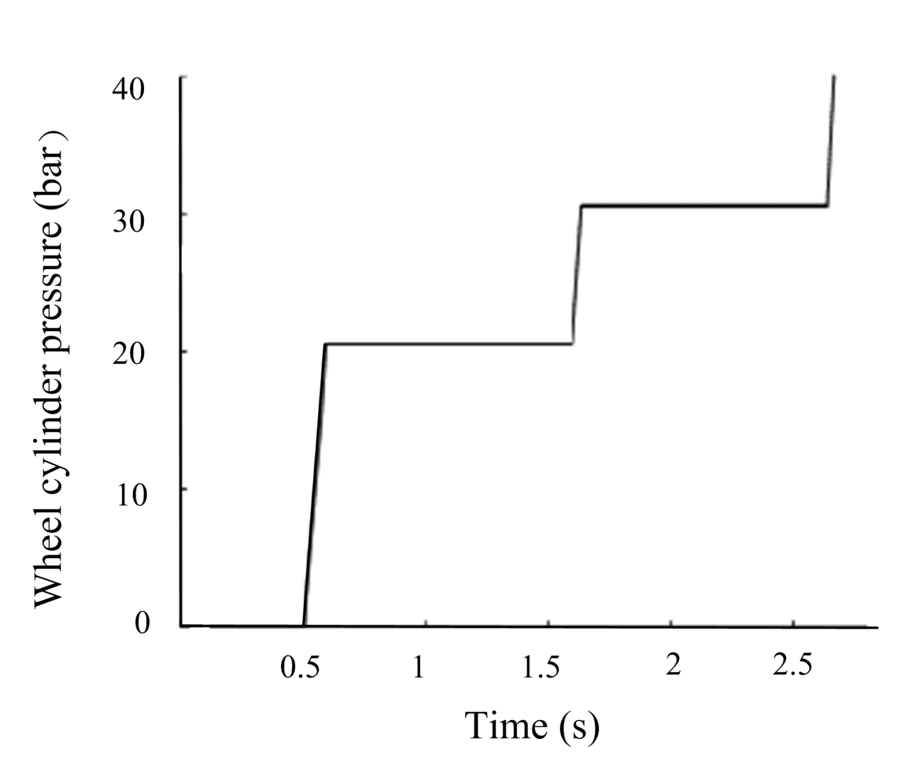
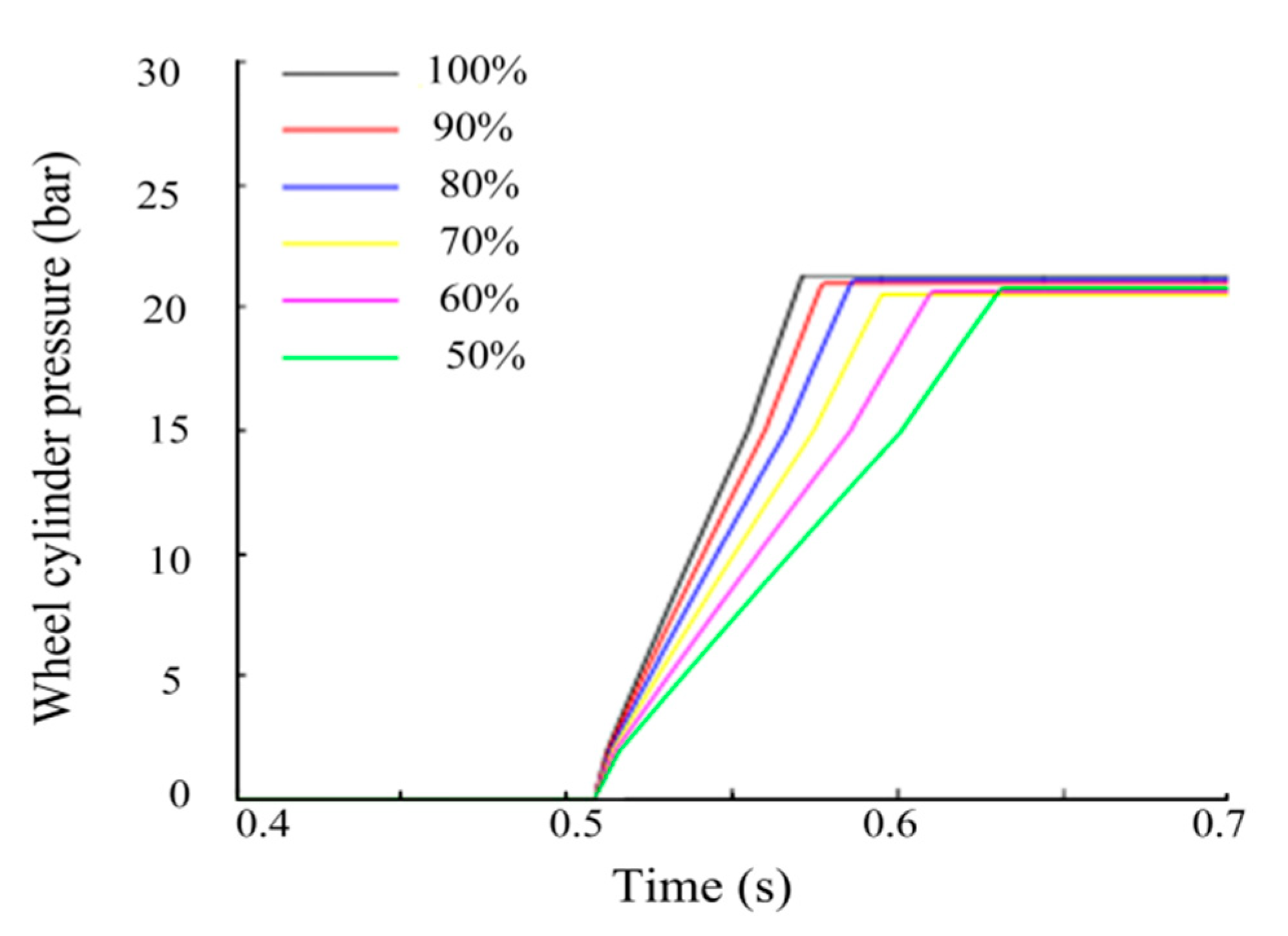
The control accuracy of the new HCU is of great significance to the coordination of motor-hydraulic braking torque. The verification process and the simulation result are shown in Figure 6 and Figure 7.
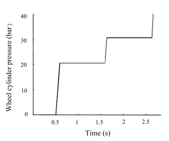
Figure 6.
Simulation results of the hydraulic control model.
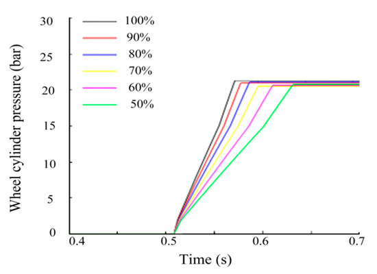
Figure 7.
The effect of the boost valve duty cycle on the boosting process.
Figure 7 shows that during the boosting process, the boosting rate will increase with an increase in the duty cycle. Conclusions can be made that the boosting rate and the accuracy can be determined by controlling the duty cycle.
2.3. Analysis of the Braking Force
For the analysis of braking force distribution, certain simplifications of vehicle dynamics were made in order to derive the ideal braking force distribution curve. The main assumptions are as follows:
- (1)
- For a given braking scenario, the tire–road adhesion coefficient μ is assumed constant to establish the theoretical relationship between front and rear axle braking forces.
- (2)
- The dynamic load transfer during deceleration is considered through the vehicle CG height (h) and the longitudinal distance from the CG to the rear axle (a), as expressed in Equation (1). However, higher-order nonlinear effects such as suspension compliance, vehicle pitch motion, and road irregularities are neglected for simplicity.
- (3)
- In subsequent simulations, variable adhesion conditions and more detailed load transfer dynamics are incorporated to enhance the reliability of control strategy validation.
When the front wheel and rear wheel are locked simultaneously, and the braking force is distributed as follows:
where is the wheel base, represents the longitudinal distance from the center of gravity (CG) to the rear axle, is the height of vehicle CG, and and are the braking forces of the front wheel and rear wheel, respectively.
The braking force distribution coefficient is defined as:
where is the total braking force of the front and rear wheels. Then, the relationship between the braking force of the front and rear wheels is:
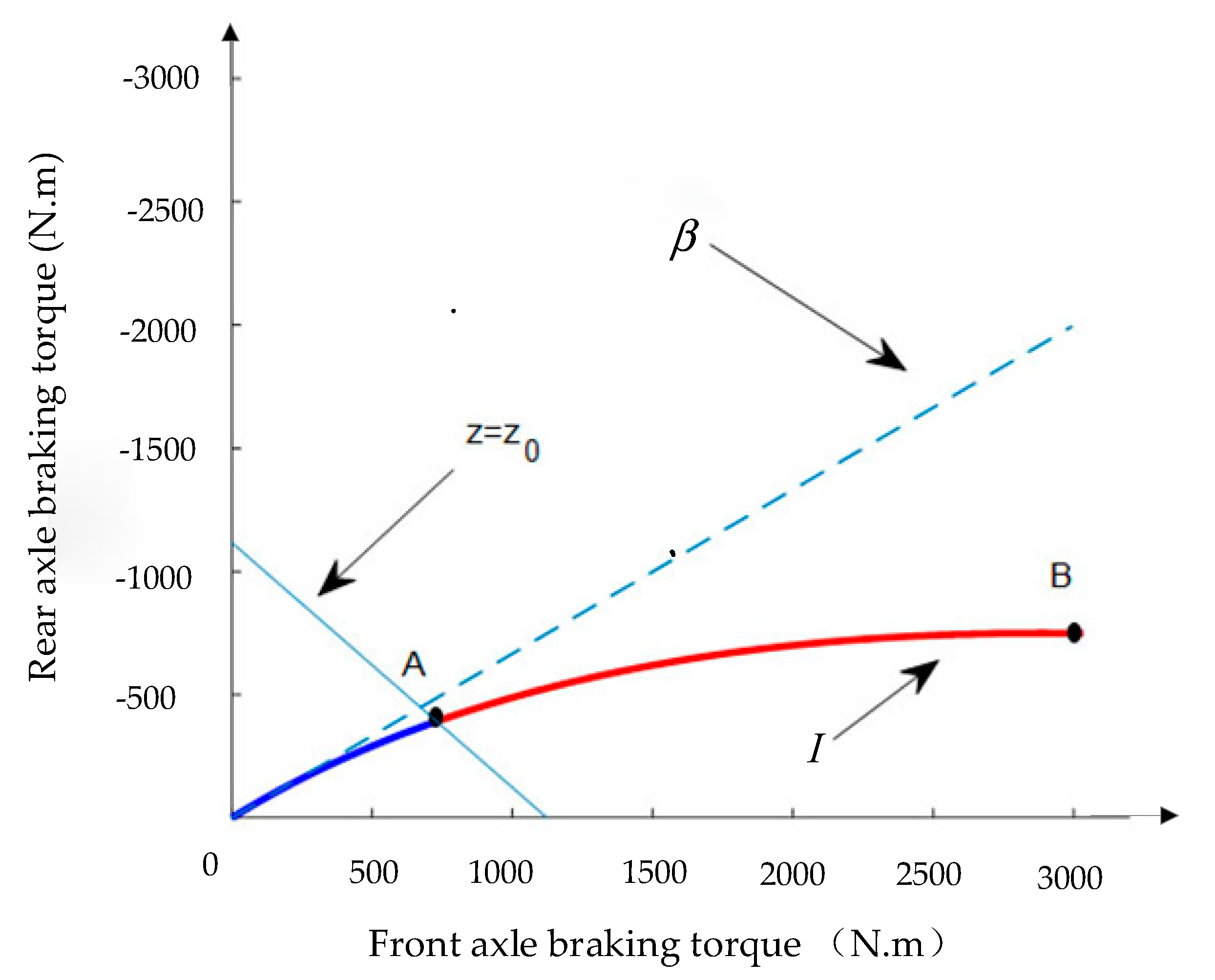
According to (2) and (3), the curve I and the fixed proportion distribution curve can be obtained as shown in Figure 8.
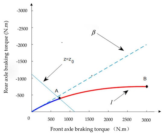
Figure 8.
Braking force distribution curve of the front and rear axles.
3. Electro-Hydraulic Coordination Braking Control Strategy
3.1. Brake Mode Judgement
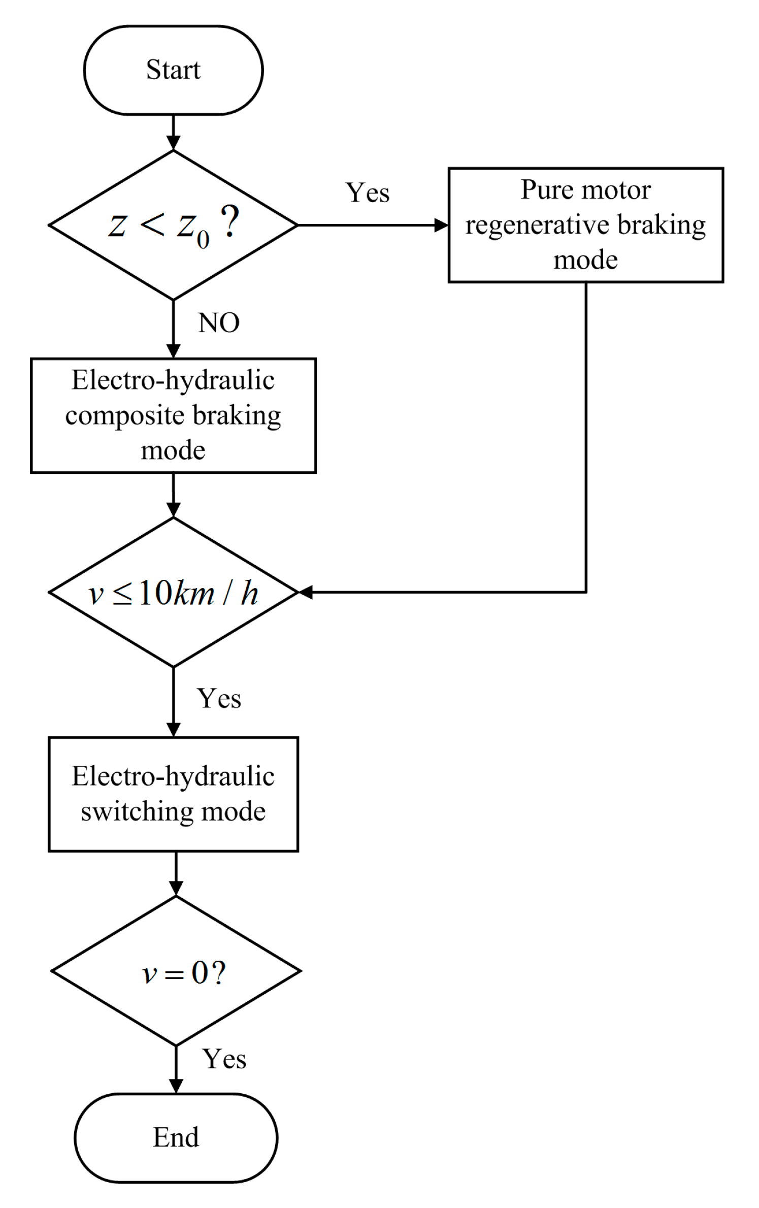
This paper introduces pure motor regenerative braking mode, electro-hydraulic composite braking mode and electro-hydraulic switching mode, three braking modes. Different braking modes are adopted according to the target braking intensity and the vehicle speed , as shown in Figure 9. The details are as follows:
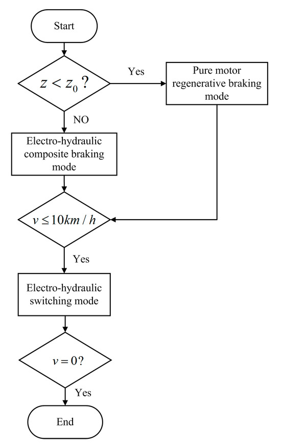
Figure 9.
The flow chart for determining the braking mode of the electro-hydraulic composite brake.
When , km/h, the pure motor regenerative braking mode is activated, and the braking force is only provided by the motor braking force. The requirement of the braking intensity is low, and the main goal of the system is to recover the braking energy.
When , km/h, the electro-hydraulic composite braking mode is selected, and the motor braking torque and hydraulic braking torque coordinate to complete the braking. The braking intensity requirement is high, and priority should be given to the braking intensity.
When km/h, the system enters into the electro-hydraulic switching mode, in which the motor braking torque is slowly withdrawn, and the desired torque is supplemented by the hydraulic braking torque. This is necessary because the motor can not charge the battery at such a low speed.
During the braking process, if a wheel locking trend is detected, the system will switch to ABS mode.
3.2. Braking Force Distribution Strategy
In pure motor regenerative braking mode, the distribution of the front and rear axle braking torque is given according to the OA segment in Figure 8; that is, it is based on curve I. The calculation formula is shown in (4).
where and are the motor braking torque of the front wheel and rear wheel, respectively; is the mass of the vehicle; denotes the acceleration of gravity; represents the wheel radius; and is the longitudinal distance from the CG to front axle.
In electro-hydraulic composite braking mode, the front and rear axle braking forces are distributed according to the AB segment shown in Figure 8. To ensure that the motor braking torque can effectively reduce the overall braking torque when the wheel is locked, the motor braking torque and the hydraulic braking torque are evenly distributed. The motor braking torque and the hydraulic braking torque of the left front wheel and the left rear wheel are calculated as follows:
where and are the hydraulic braking torque of the front wheel and rear wheel, respectively.
3.3. The Anti-Lock Braking Control Strategy Based on Pure Motor Torque Adjustment
The formula of the slip ratio is defined as:
where is the rolling wheel radius, and is the wheel angular velocity.
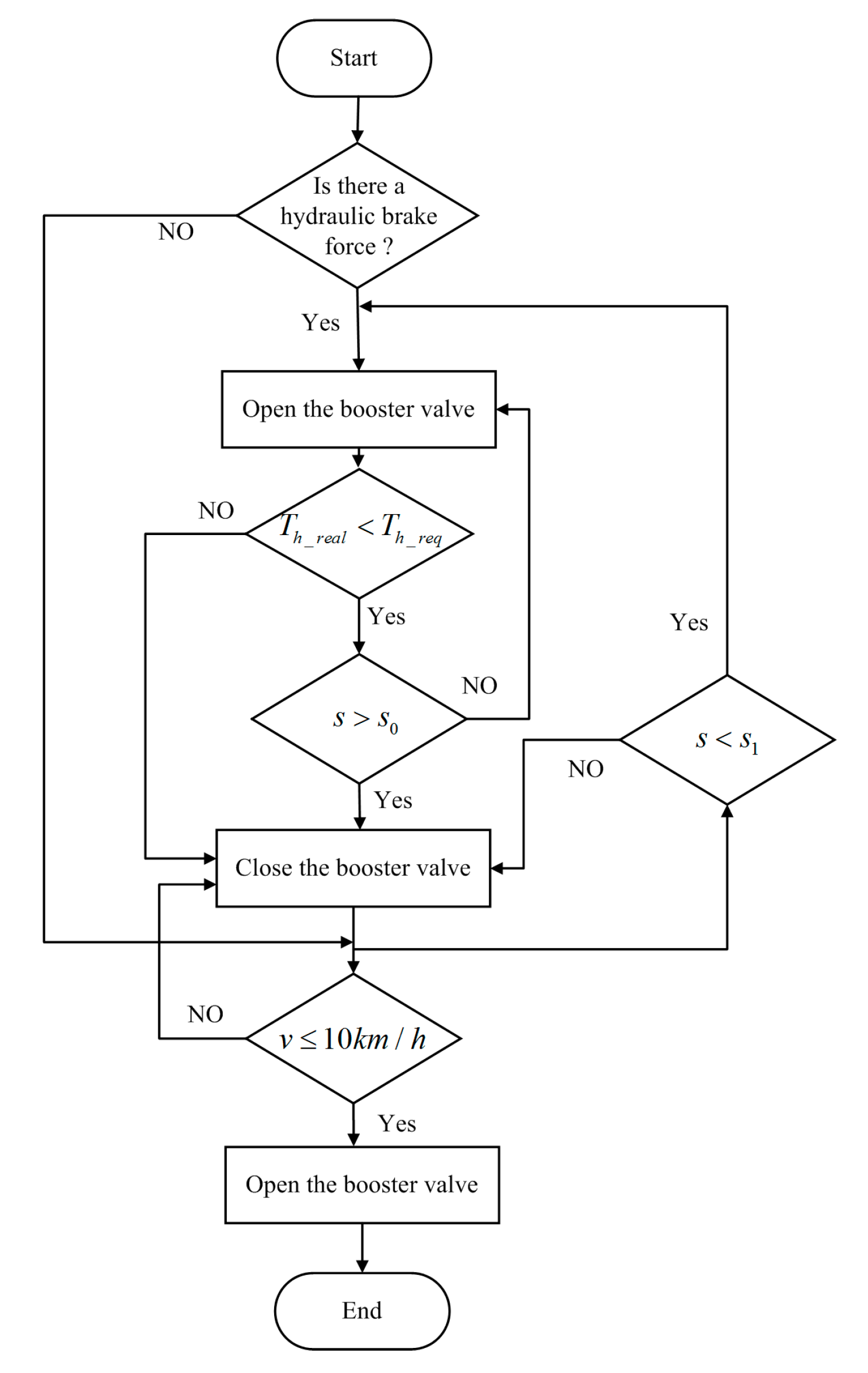
In this research, the hydraulic braking force cannot be reduced. Torque is reduced by switching the motor braking torque to the reverse driving torque, which regulates the wheel state when the total braking torque needs to be greatly reduced in the ABS mode. The description of the hydraulic braking torque strategy and motor braking torque strategy in the ABS process are shown in Figure 10.
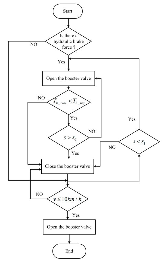
Figure 10.
Control strategy flow chart of the hydraulic brake system.
When in the pure motor regenerative braking mode, the boost valve is closed until the speed drops below 10 km/h. In the electro-hydraulic composite braking mode, the booster valve opens unless the hydraulic braking torque reaches the target torque . Once the speed is reduced to 10 km/h, the booster valve remains open while the ABS mode is stopped.
Another special case is also considered in this paper. When the vehicle is driving on a road with a low adhesion coefficient, the hydraulic braking torque fails to reach the target torque. A wheel slip rate indicates that the wheel tends to be locked. This moment, the booster valve is closed and the hydraulic braking torque remains unchanged. When the vehicle drives on a road with a high adhesion coefficient, the wheel slips. The booster valve is opened again until the target torque is reached. When the vehicle speed is reduced to 10 km/h, the booster valve opens and the anti-lock control process ends.
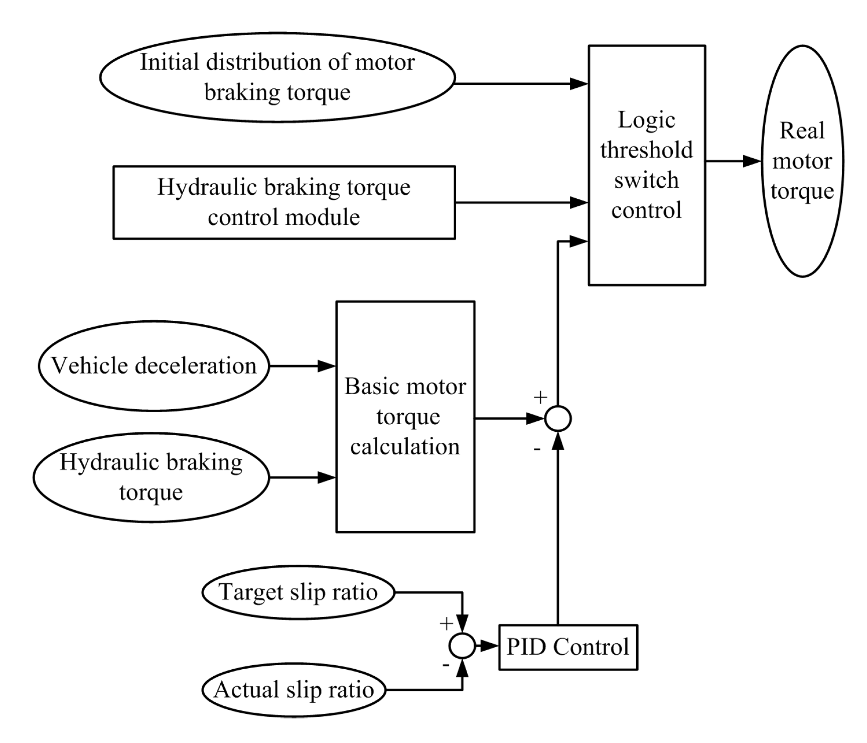
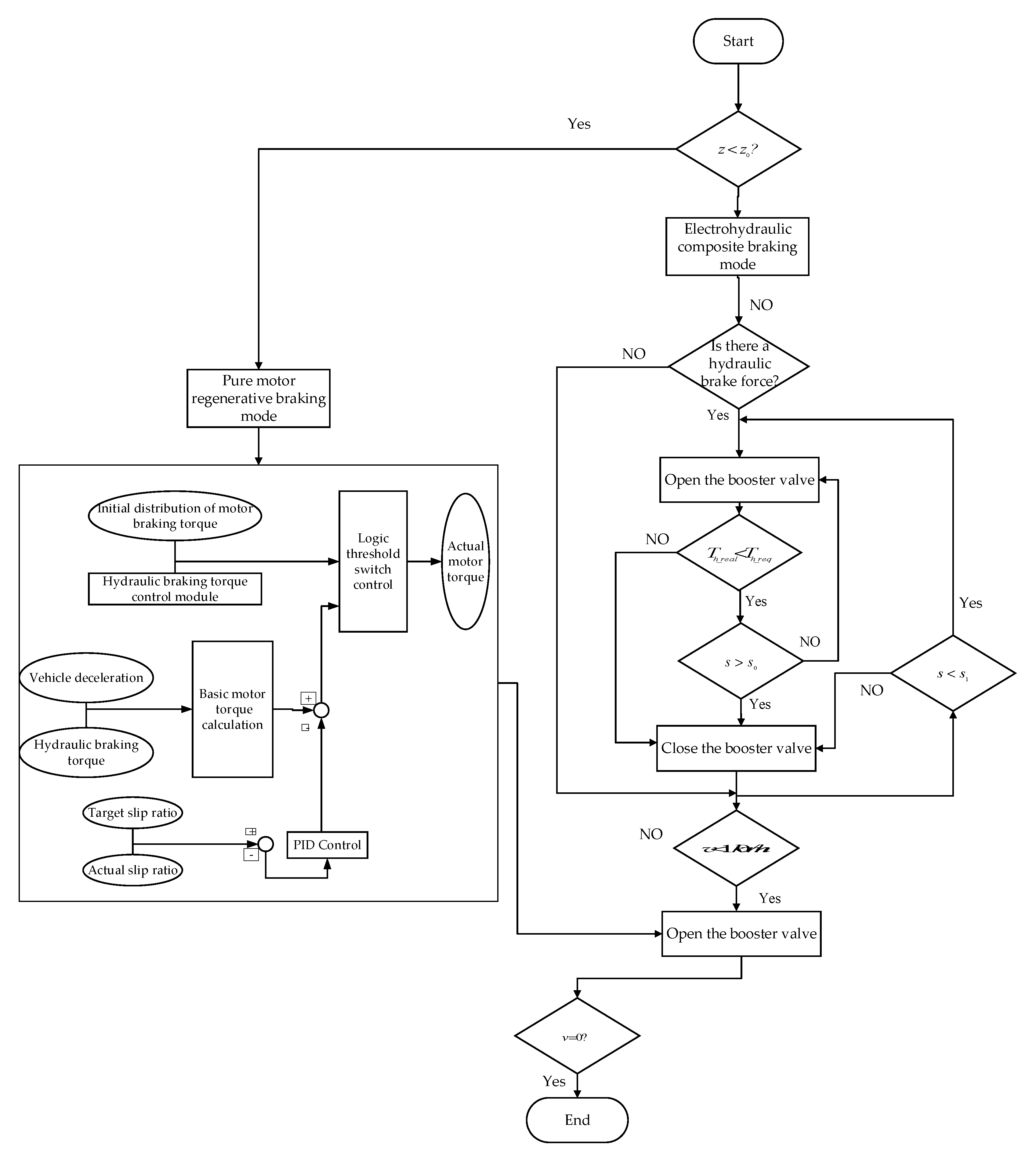
PID control, which is a nonmodel-based control, is characterized with perfect robustness. This paper uses a control method combining the PID controller with the logic threshold to control the motor torque. The overall process is shown in Figure 11. The overall schematic of the proposed cooperative control strategy for braking force distribution in the electro-hydraulic hybrid braking mode is illustrated in Figure 12.
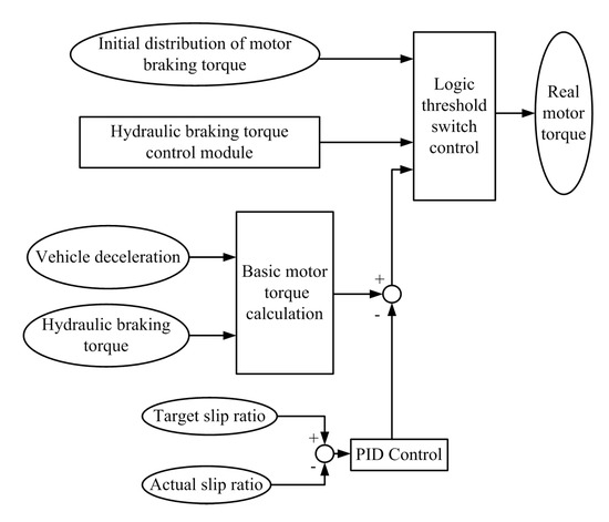
Figure 11.
Motor torque control strategy diagram.
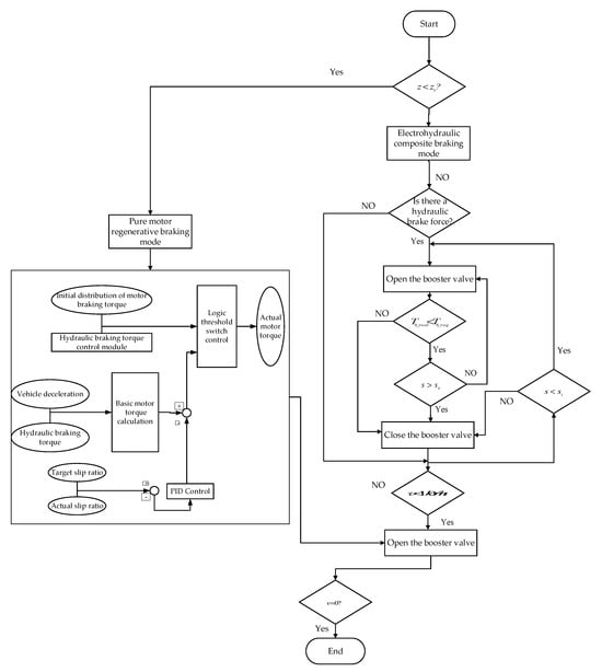
Figure 12.
Cooperative Control Strategy for Braking Force Distribution in Electro-Hydraulic Hybrid Braking Mode.
Firstly, the braking force distribution of the front and rear axles, as well as the motor and hydraulic braking forces, are determined by III.B. The booster valve is closed when the hydraulic braking torque reaches the threshold value, and then the pure motor ABS control module is activated. The basic motor torque of the front wheel and rear wheel are calculated according to the deceleration and the real hydraulic braking torque and . The calculation formula is shown in (24).
In addition, the PID controller corrects motor torque by sensing the difference between the actual slip rate and the target slip rate. The difference between the correction torque and the basic motor torque is calculated, forming a closed loop control.
The hydraulic braking torque control module is used as the switch to coordinate the braking torque between the motor and HCU. When the hydraulic braking torque begins to adjust, the ABS control is turned off, and the motor torque is set to the initial distribution torque. When the adjustment of the hydraulic braking torque is completed, the ABS control is turned on, which can avoid interference between the motor torque and the hydraulic braking torque. When the speed is less than 10 km/h, the ABS control is turned off.
4. Simulation and Analysis
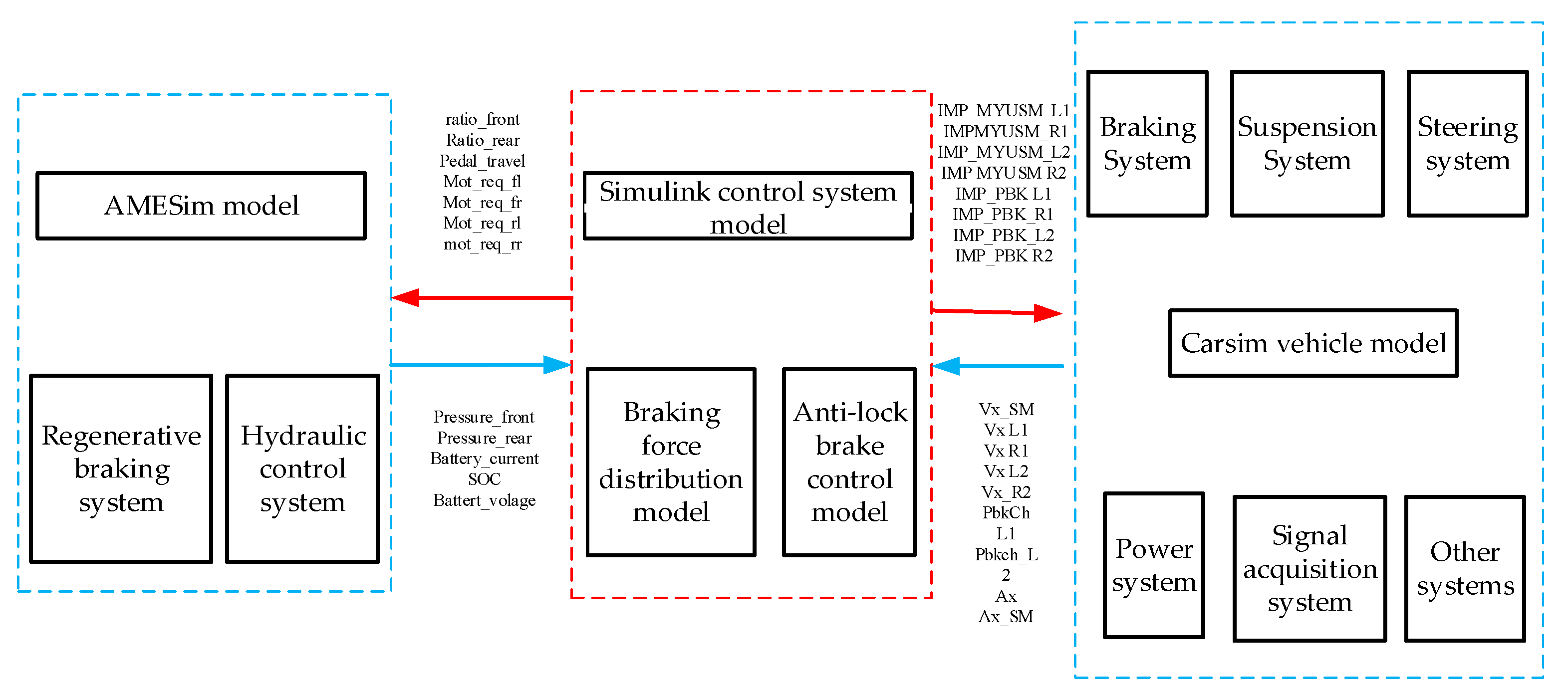
The overall control strategy model, comprising the braking force distribution model and the anti-lock braking control model, was developed in Simulink. The regenerative braking system model—including the in-wheel motor, motor controller, and battery—and the hydraulic control system model—containing the brake master cylinder and hydraulic control unit (HCU)—were constructed using AMESim. A full-vehicle model incorporating the braking system, suspension system, steering system, powertrain, signal acquisition system, and other subsystems was built in CarSim. The Simulink module communicated with both the AMESim and CarSim models via S-functions, which were used to send control commands and acquire signals from corresponding sensors
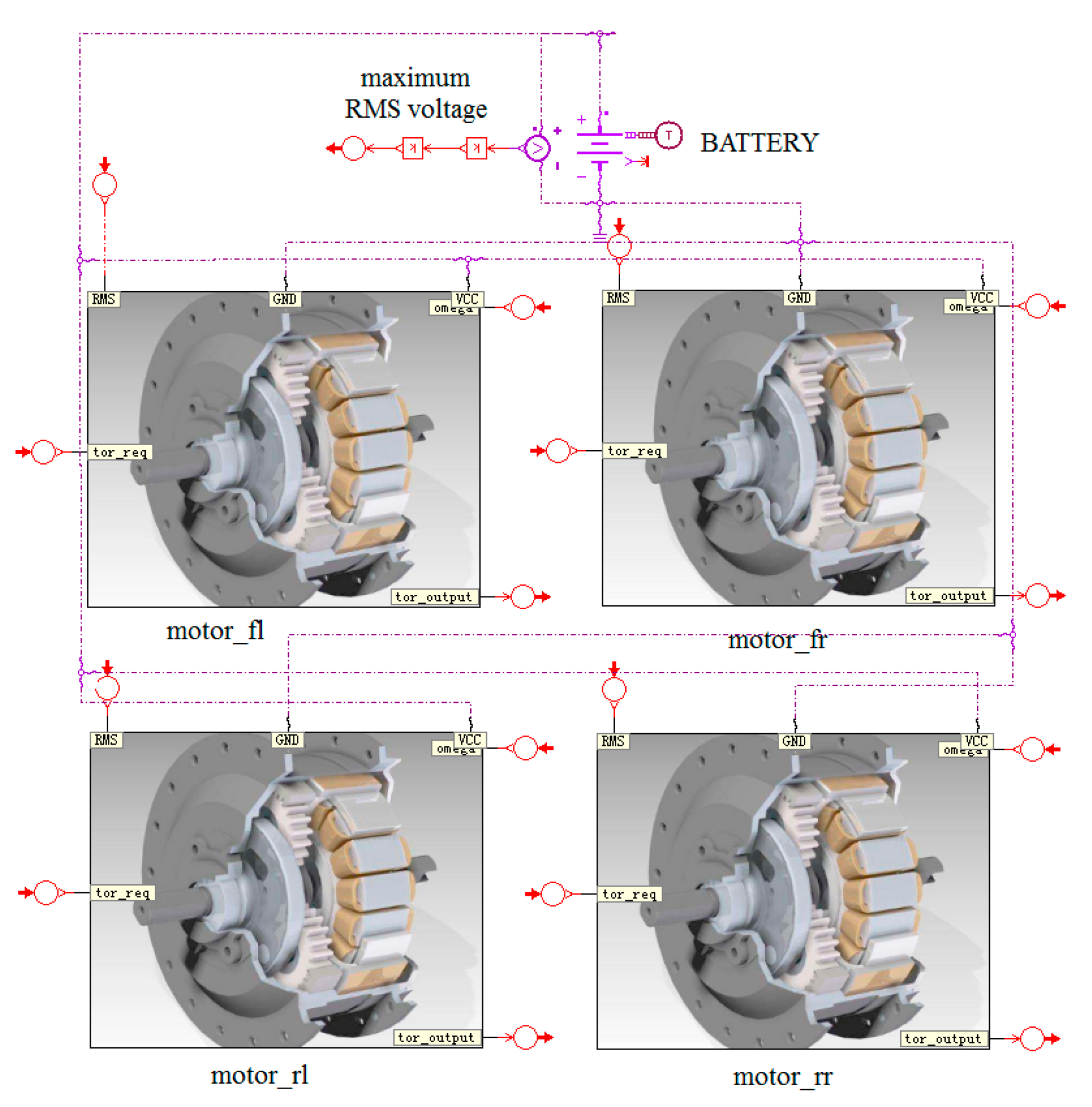
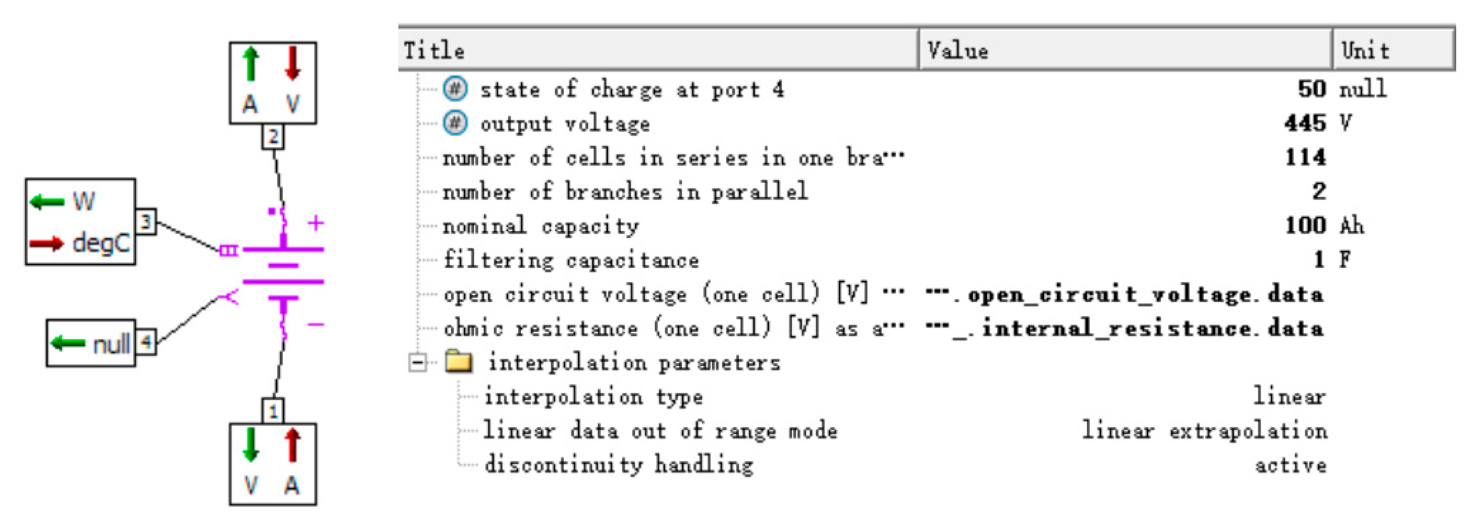
Using the Electric Motors and Drives library in AMESim, a regenerative braking system model was established, as shown in Figure 13 The model consists of three main components: the power battery, motor controller, and motor. As shown in Figure 14, a power battery model was developed in AMESim. The output voltage, battery capacity, and cell configuration were specified in the parameter setting mode to accurately represent the electrical characteristics of the traction battery.The motor controller receives torque commands from the electro-hydraulic braking system controller, converts the two-phase DC power from the battery into three-phase AC power, and supplies it to the motor. The motor feeds back its operating status to the controller, enabling closed-loop control to ensure the motor accurately tracks the target torque. As the actuator of the regenerative braking system, the motor’s performance is critical to both braking energy recovery and the realization of ABS functionality.
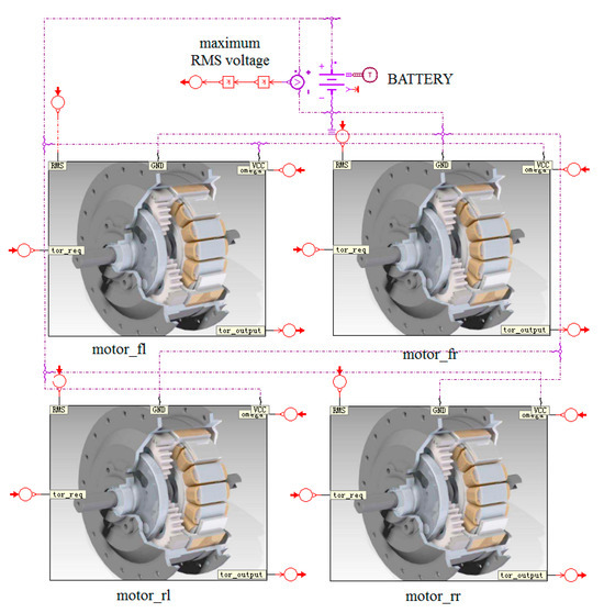
Figure 13.
Regenerative braking system model.
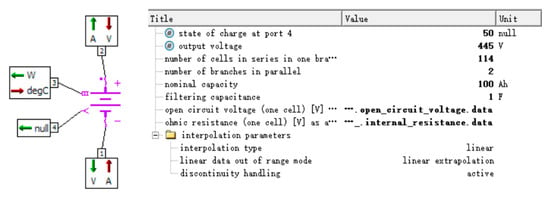
Figure 14.
Power Battery Model.
In this study, the vehicle model is established in CarSim. The key parameters of the vehicle model are given in Table 1. AMESim is used to build the RBS model and the hydraulic control system model. The overall control strategy model is built by Simulink. The overall structure of the electro-hydraulic composite braking system proposed is shown in Figure 15.

Table 1.
The vehicle parameters.
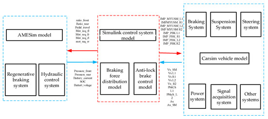
Figure 15.
The overall structure of the electro-hydraulic composite brake system simulation platform.
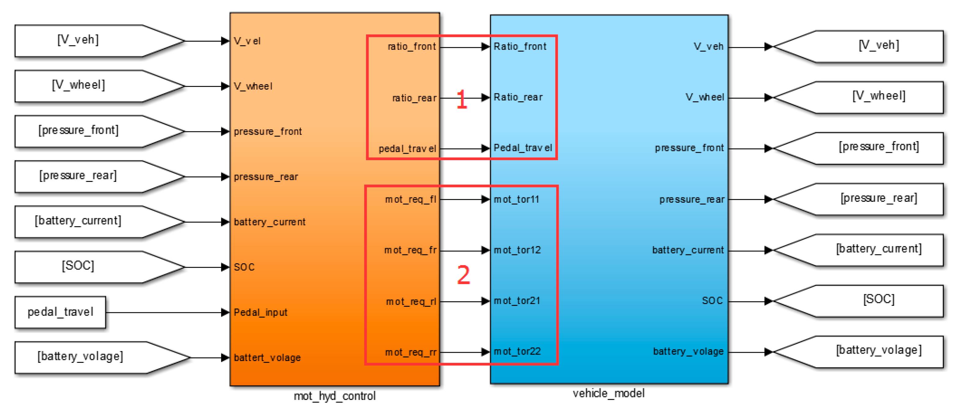
Following the development of the hydraulic control and regenerative braking system models, the control model for the electro-hydraulic hybrid braking system was implemented in Simulink, as illustrated in Figure 16. The control model primarily consists of two parts: a motor-hydraulic braking force control module and an interface module that facilitates communication with the full-vehicle model (CarSim), the hydraulic plant model (AMESim), and the regenerative braking subsystem (AMESim). By processing real-time vehicle state inputs through its internal algorithms, the control model generates outputs for Module 1 and Module 2. Module 1 is responsible for regulating the hydraulic braking torque, while Module 2 controls the motor torque, thereby establishing an integrated closed-loop control system.
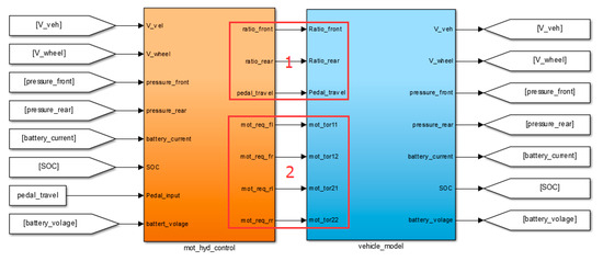
Figure 16.
Overall Control Strategy Model.
Additionally, an ABS control model based on the coordinated regulation of motor torque and hydraulic braking torque was developed in Simulink. Corresponding co-simulation interfaces were configured to integrate this ABS controller with the conventional hydraulic control unit model, the regenerative braking system, and the full-vehicle model. A detailed description of these interfaces is omitted here for brevity.
4.1. Simulation of the Normal Braking Condition
The research goal of this paper is to recover as much braking energy as possible under the premise of ensured braking stability.
The braking energy recovery rate refers to the ratio between the recoverable energy and the total energy consumed in the braking process, which is defined as:
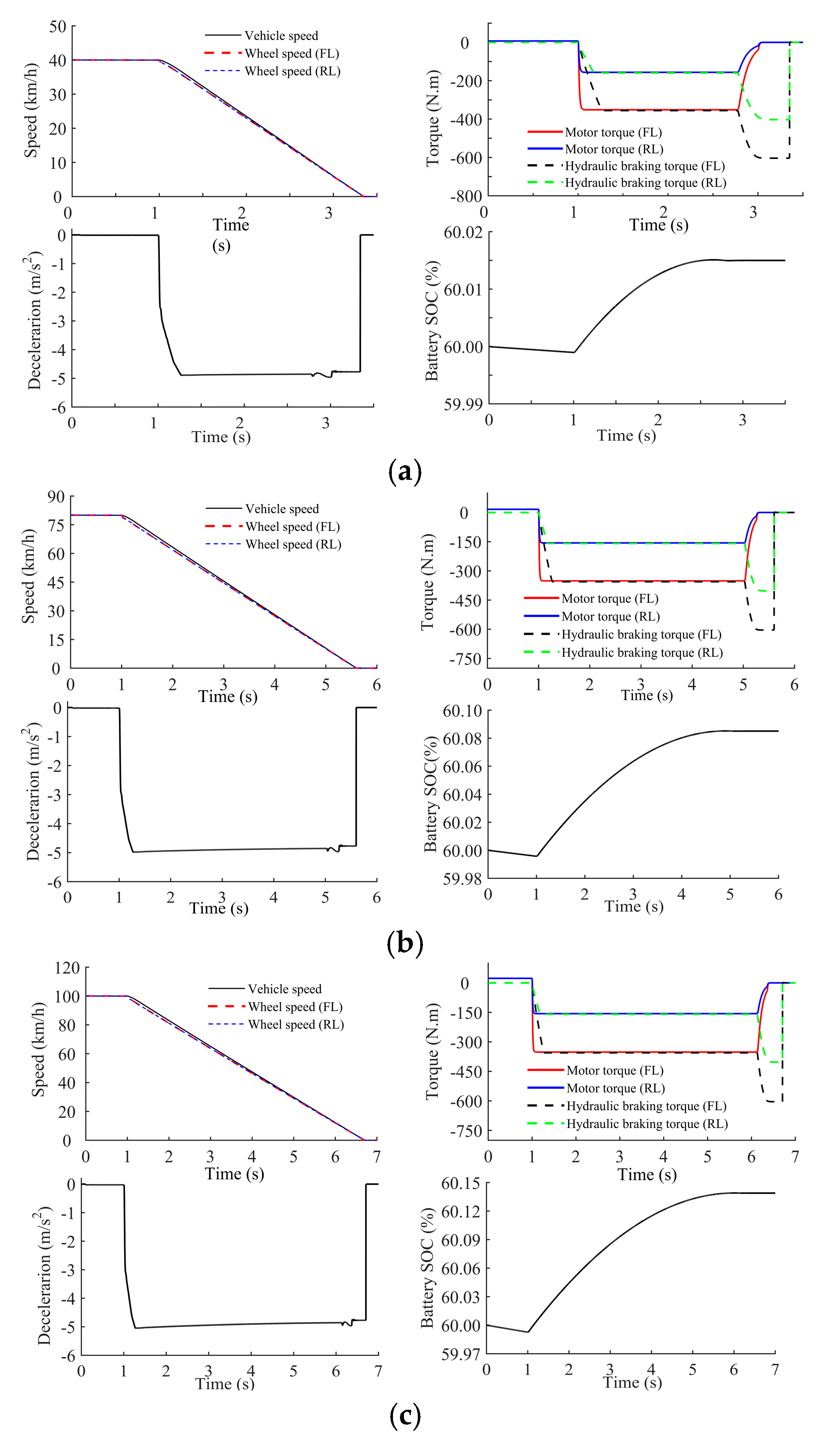
For normal braking conditions, the braking intensity of the low-intensity braking condition, medium-intensity braking condition and high-intensity braking condition are set as z = 0.2, z = 0.5, z = 0.7, respectively. The initial braking speeds are selected as 40 km/h, 80 km/h, and 100 km/h, where FL stands for front left wheel and RL stands for rear left wheel.
According to Section 3, the requirement torque of the low-braking intensity is low and the system is in the pure motor regenerative braking mode.
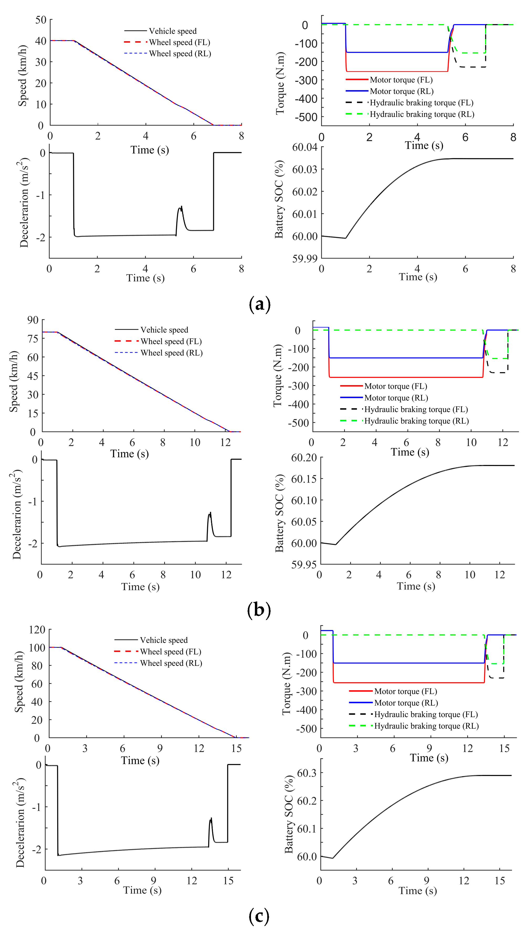
Figure 17a–c present the simulation results at a braking intensity with initial braking speeds of 40 km/h, 80 km/h, and 100 km/h, respectively. Each figure includes the variation curves of velocity, torque, deceleration, and battery SOC.
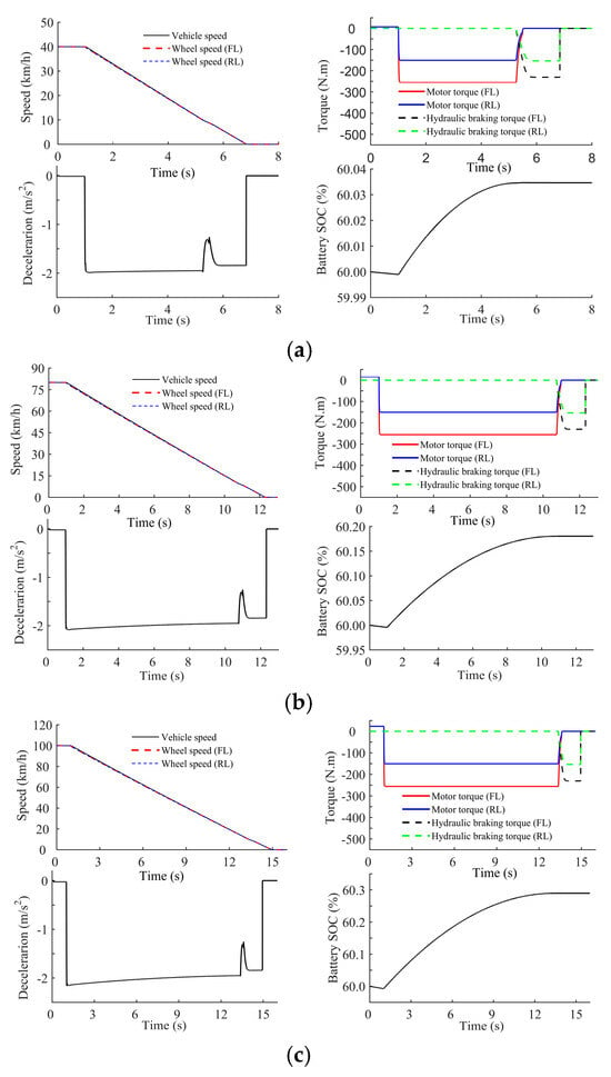
Figure 17.
Simulation results under low braking intensity (). (a) The initial braking speed is 40 km/h. (b) The initial braking speed is 80 km/h. (c) The initial braking speed is 100 km/h.
When 10 km/h, the braking force is provided by the in-wheel motors while the hydraulic braking torque is zero. The hydraulic braking torque starts to work when the vehicle speed drops below 10 km/h.
The braking deceleration can be essentially maintained at , including the switching process, which means the switching process is relatively stable.
The battery SOC increases with time until the vehicle speed drops below 10 km/h.
By comparing Figure 17a–c, it can be determined that as the initial braking speed increases, the magnitude of SOC increases continuously. This result is because the kinetic energy can be recovered by the vehicle increasing with an increase in the initial braking speed.
Through Figure 17a–c, we can calculate the total energy consumed, the recovered energy and the braking energy recovery rate at three initial braking speeds under low-intensity braking conditions, as shown in Table 2.

Table 2.
Energy recovery of low-intensity braking.
Table 2 shows that the braking energy recovery rate under the condition of low-intensity braking is high, up to 80%. The braking energy recovery rate increases with an increase in initial braking speed. This result is because, on one hand, the ratio of the braking energy recovery time to the unrecovered time at a high speed is great, while on the other hand, the power generation efficiency of the motor at a low speed is in the low efficiency region.
When brakes on medium-intensity braking condition, the electro-hydraulic composite braking mode is activated to ensure the braking stability. Braking forces are distributed according to Section 3.
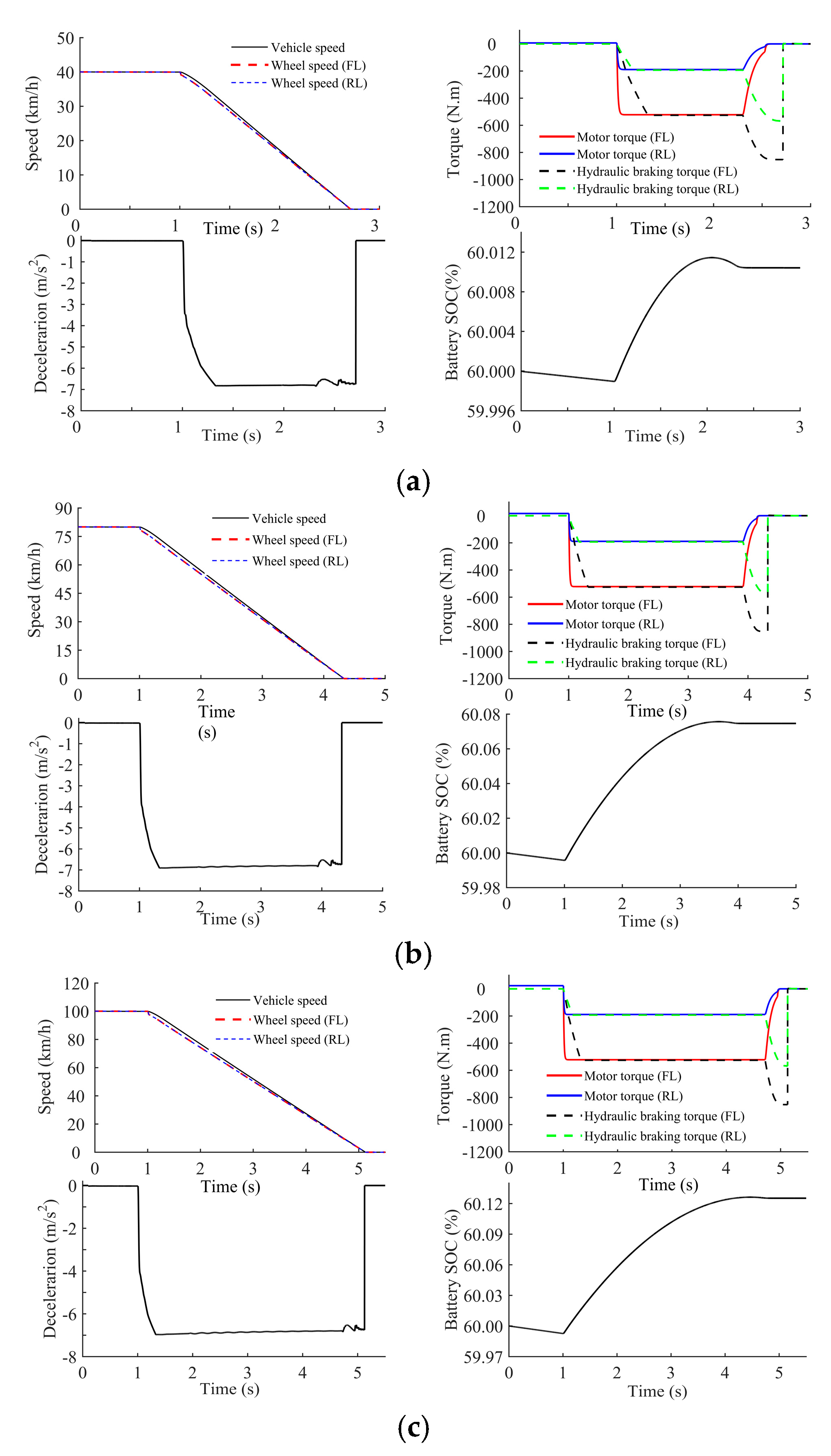
Figure 18a–c present the simulation results at a braking intensity z = 0.5 with initial braking speeds of 40 km/h, 80 km/h, and 100 km/h, respectively. Each figure includes the variation curves of velocity, torque, deceleration, and battery SOC.
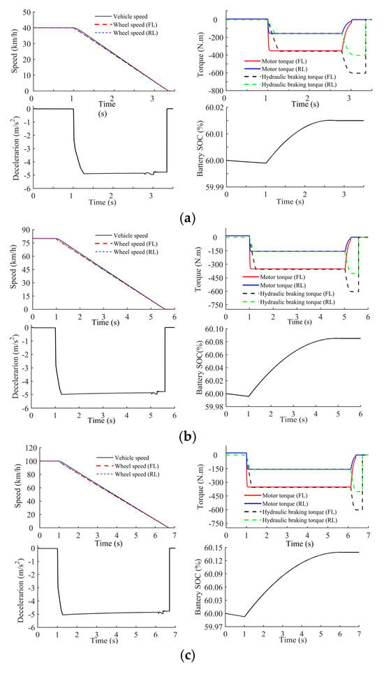
Figure 18.
Simulation results under medium braking intensity (z = 0.5). (a) The initial braking speed is 40 km/h. (b) The initial braking speed is 80 km/h. (c) The initial braking speed is 100 km/h.
Figure 18 shows that (1) When 10 km/h, the motor braking torque and the hydraulic braking torque are evenly distributed. (2) The braking deceleration can be basically maintained at approximately , which is consistent with the target braking intensity. (3) Due to the participation of the hydraulic braking torque, the magnitude of SOC increases less than that in the low-intensity braking condition.
It can be concluded from the data shown in Table 3 that the braking energy recovery rate increases with the initial braking speed. Additionally, the braking energy recovery rate can reach approximately 30% under medium-intensity braking conditions, which is lower than that under low-intensity braking conditions.

Table 3.
Energy recovery performance under medium-intensity braking.
The electro-hydraulic composite braking mode is activated to ensure braking stability under high-intensity braking condition.
Figure 19a–c present the simulation results at a braking intensity z = 0.7 with initial braking speeds of 40 km/h, 80 km/h, and 100 km/h, respectively. Each figure includes the variation curves of velocity, torque, deceleration, and battery SOC.
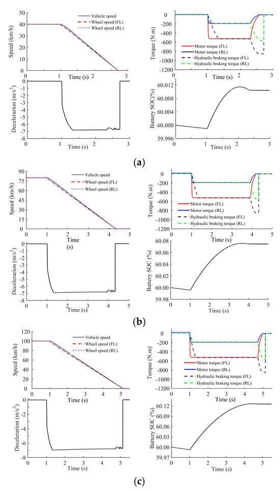
Figure 19.
Simulation results under high braking intensity (). (a) The initial braking speed is 40 km/h. (b) The initial braking speed is 80 km/h. (c) The initial braking speed is 100 km/h.
Figure 19 shows that (1) When 10 km/h, the motor braking torque and the hydraulic braking torque are evenly distributed. (2) The braking deceleration can be essentially maintained at approximately and the switching process is smooth. (3) The SOC increase is comparatively small under high braking intensity. This can be attributed to the dominant share of hydraulic braking in this condition.
Conclusions can be made from Table 4 that the braking energy recovery rate increases with the initial braking speed. Moreover, the braking energy recovery rate can reach approximately 30% under high-intensity braking conditions, which is lower than that at medium-intensity conditions.

Table 4.
Energy recovery performance under high-intensity braking.
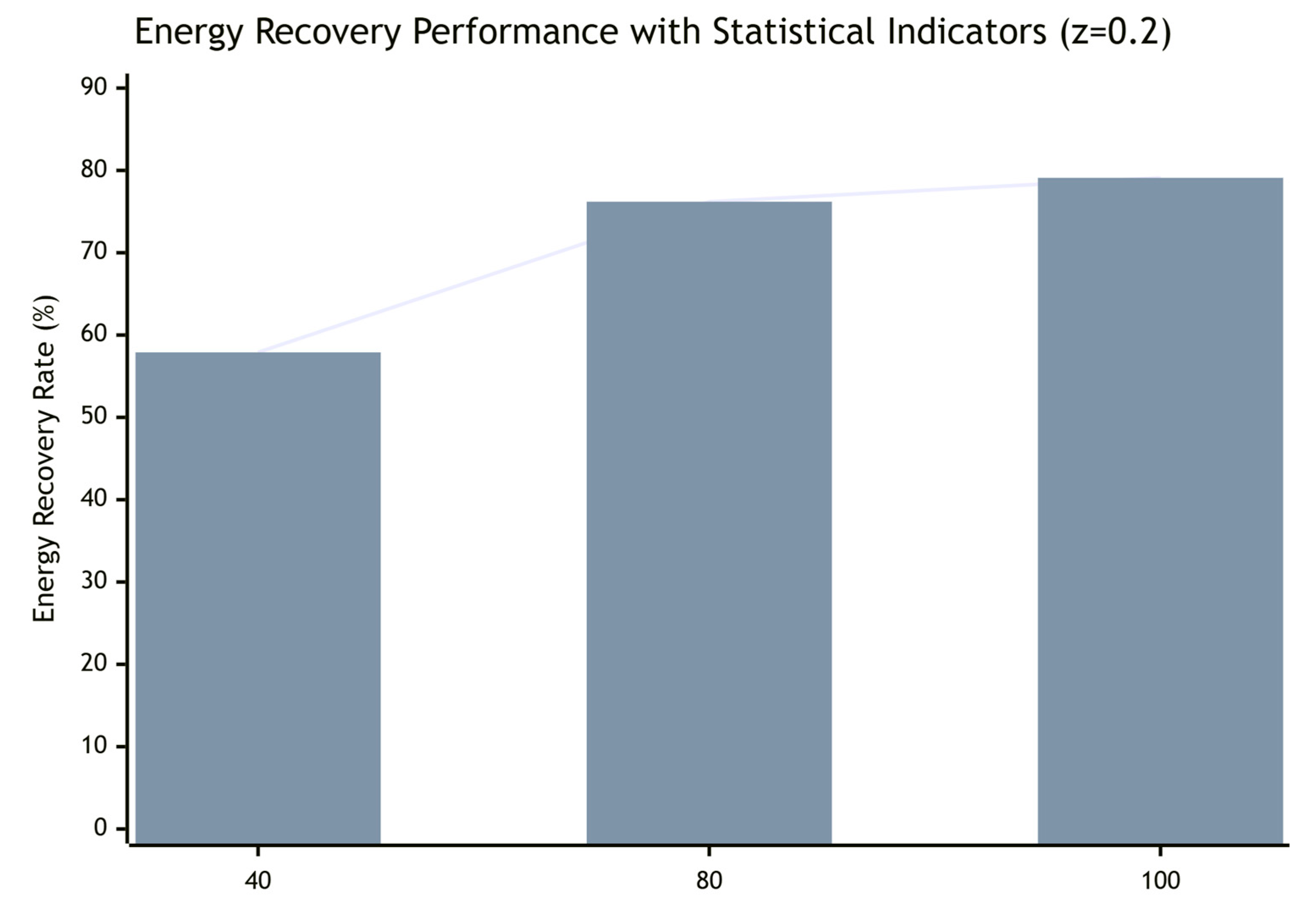
The error bars represent ±1 standard deviation derived from three repeated simulation runs, As shown in Figure 20, the average energy recovery rate under low braking intensity is presented.
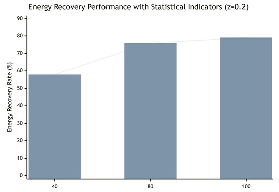
Figure 20.
Average energy recovery rate under low braking intensity (z = 0.2).
As shown in Table 5, the mean absolute slip error during braking was maintained below 1.5%, with a standard deviation of less than 0.5%, indicating high accuracy and stability in the slip ratio control.

Table 5.
Statistical Summary of Anti-lock Braking Performance Indicators.
4.2. Simulation of the Anti-Lock Braking Condition
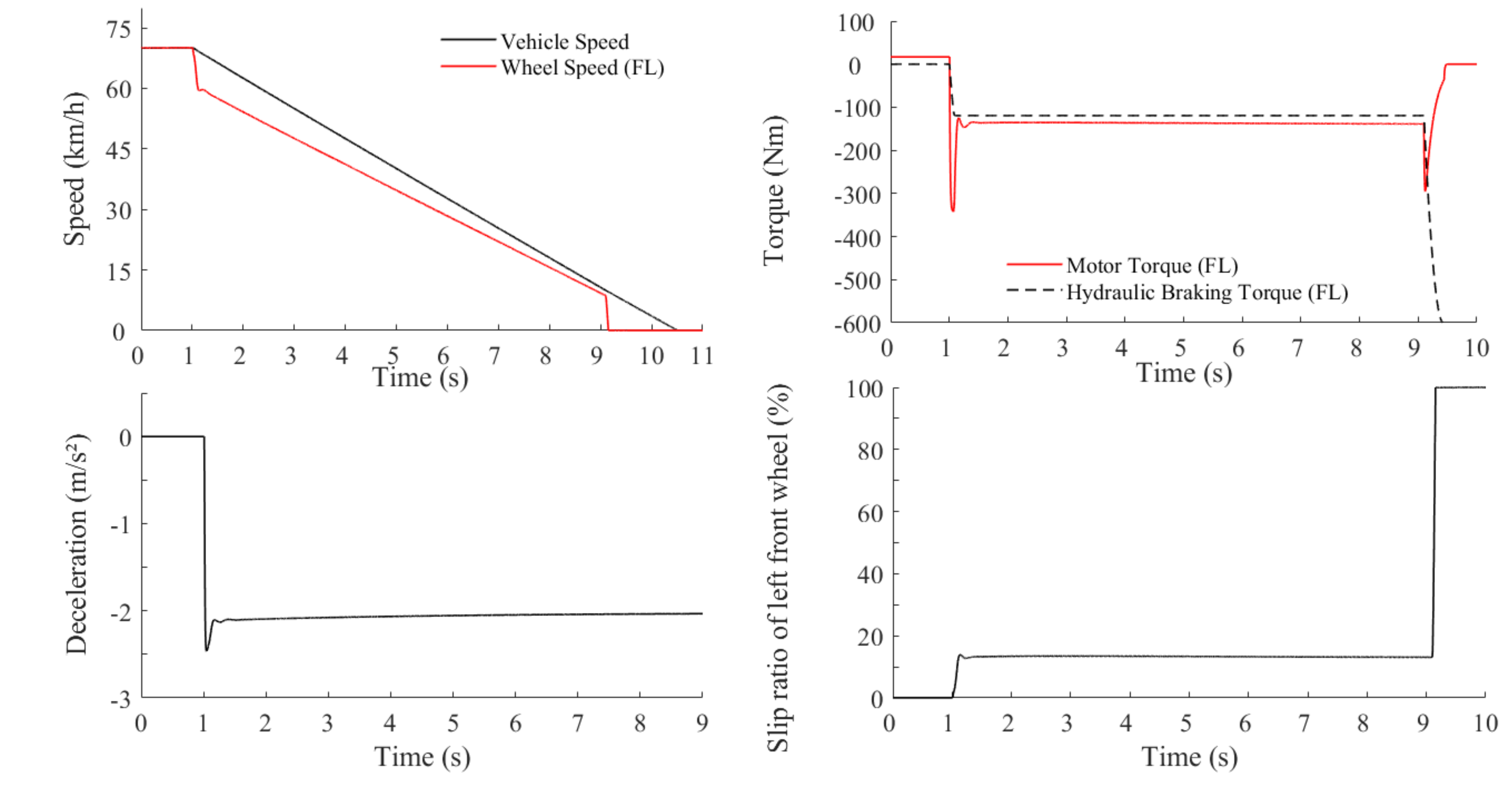
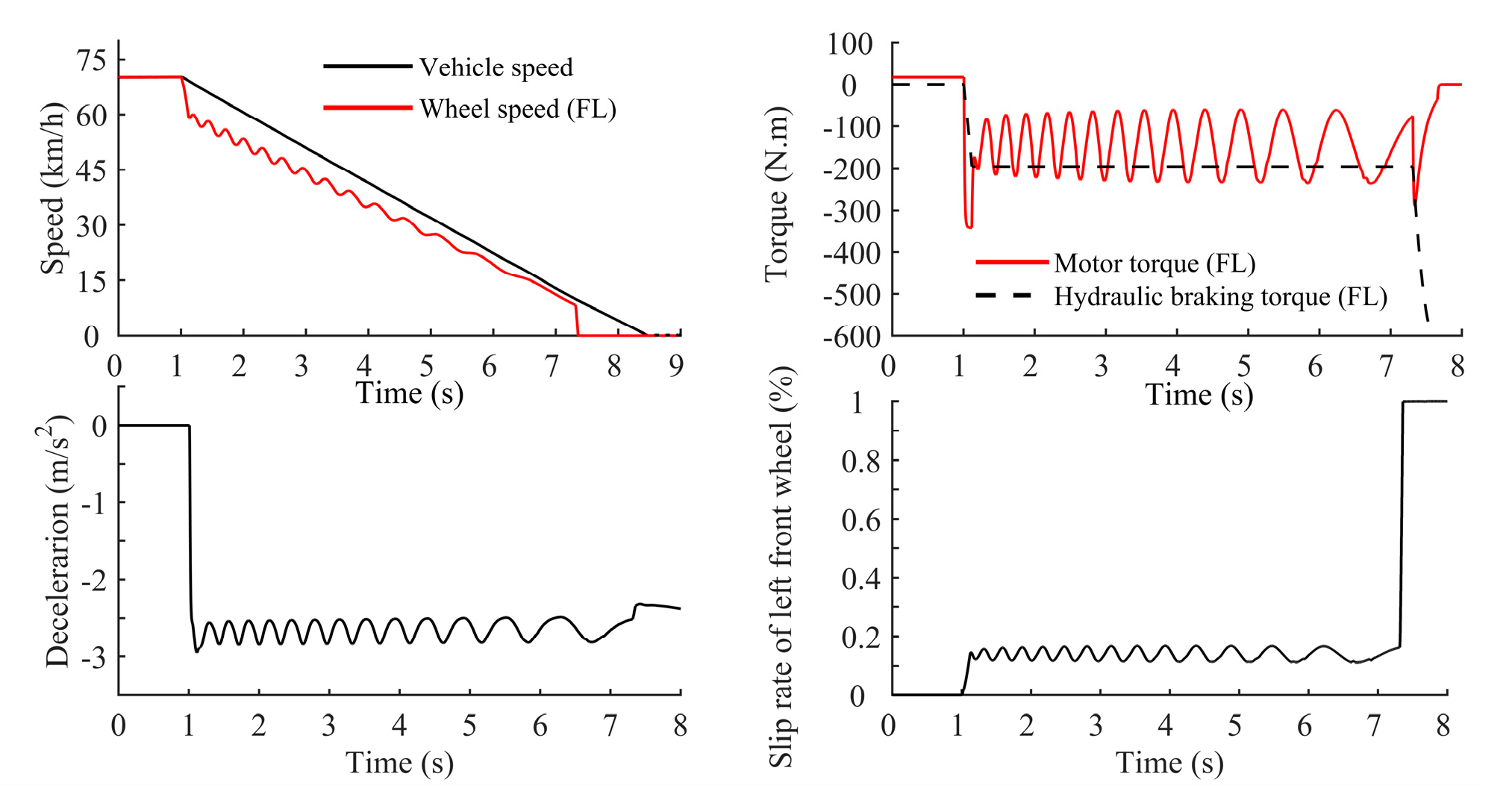
The adhesion coefficient of a snow-compacted road is 0.2, the initial braking speed is 70 km/h and the target braking strength is . The left front wheel is taken as an example.
When the vehicle brakes on a road with compacted snow, Figure 21 shows that when the wheel slips, the wheel slip rate is controlled at approximately by adjusting the motor torque and the hydraulic braking torque remains unchanged. The braking deceleration can be maintained at approximately , which is consistent with the road adhesion coefficient, which indicates that the ABS strategy makes good use of the road braking force. Once the speed is less than 10 km/h, the ABS is stopped. The hydraulic booster valve is opened to increase the hydraulic braking torque, while the motor torque is pulled out slowly.
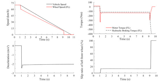
Figure 21.
Anti-lock brake control results under a snow-compacted road.
Under extremely low-adhesion conditions, the braking capability of the vehicle is constrained by the road friction limit, if a relatively high driver-requested deceleration is directly applied, the demanded braking force may exceed the available road adhesion, thereby posing a risk of wheel lock-up. The proposed electro-hydraulic coordinated braking strategy effectively prevents this by combining rapid motor regulation with hydraulic torque limiting. In the initial phase, the motor quickly delivers approximately −350 N·m of regenerative torque, while the hydraulic torque gradually increases. Once the hydraulic torque reaches a preset threshold, the system switches to the anti-lock mode: the hydraulic pressure build-up valve is closed to freeze hydraulic torque, thereby avoiding a sudden overshoot beyond the adhesion limit. At this stage, motor torque is modulated at high frequency in closed-loop control, maintaining the wheel slip ratio around 13%, which is close to the peak of the tire–road adhesion curve. Through this mechanism, the vehicle maintains a stable deceleration of approximately −2 m/s2 at μ = 0.2 and an initial speed of 70 km/h, consistent with the theoretical friction limit. As the speed drops below 10 km/h, the system exits the anti-lock mode, reopens the hydraulic valve, gradually transfers braking torque to the hydraulic system, and smoothly withdraws motor torque, thereby achieving seamless motor–hydraulic coordination. Overall, this strategy ensures braking stability and steerability while maximizing both the utilization of available road adhesion and regenerative energy recovery under extremely low-adhesion conditions.
To verify the robustness of the ABS control strategy, the road adhesion coefficient is set to a constantly changing value between and . The simulation results are shown in Figure 22.
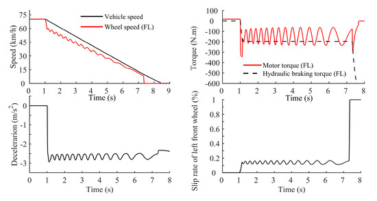
Figure 22.
Results of the anti-lock control when the braking intensity varies between and .
The results show that when the road adhesion coefficient fluctuates within a small range, the strategy can maintain the wheel slip rate at an ideal slip rate (approximately ) only by adjusting the motor torque, which proves the strategy is robust.
According to the tire adhesion–slip curve reported in [29,30,31,32], the maximum adhesion coefficient typically occurs at a slip ratio of about 10–20%. Therefore, in this study, the target slip ratio was chosen as 13–17% to ensure operation near the optimal adhesion point and to maintain braking stability.
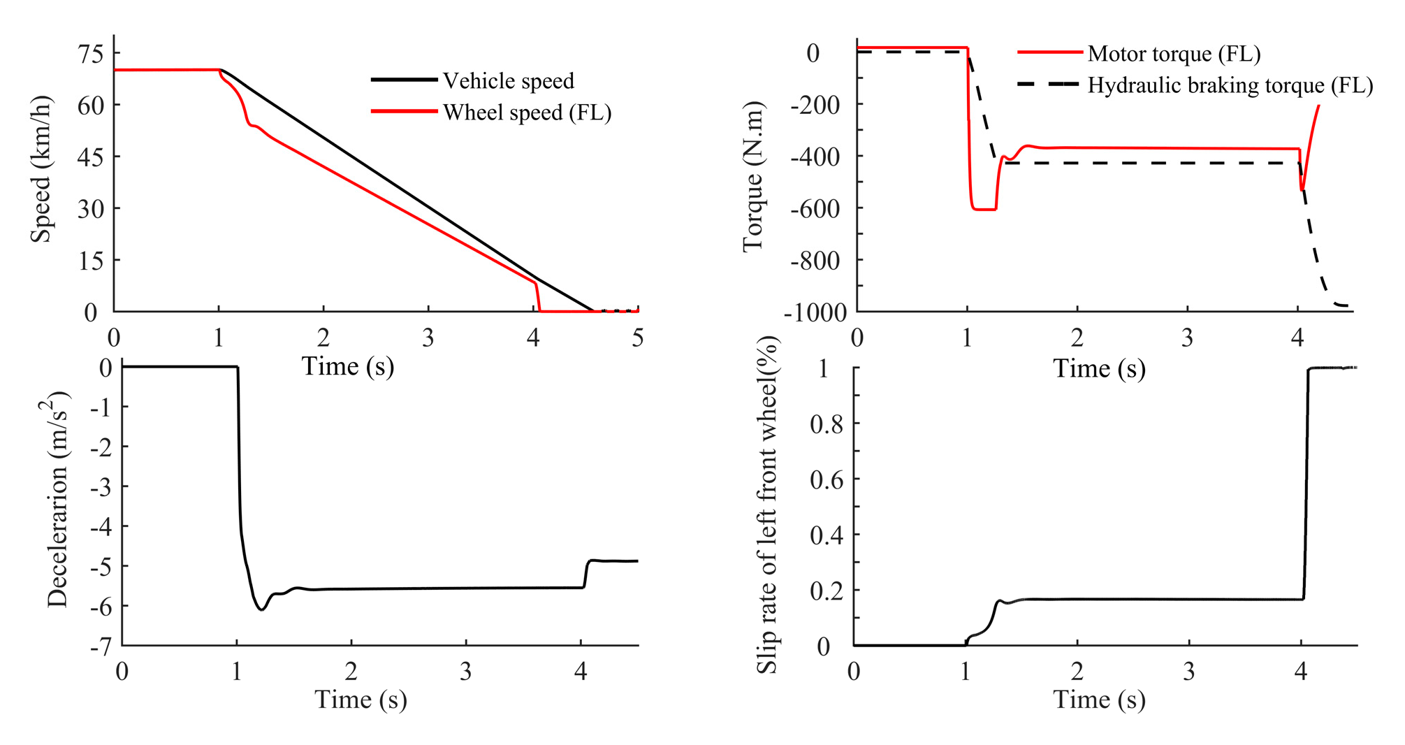
The adhesion coefficient of wet asphalt pavement is , the initial braking speed is 70 km/h and the target braking strength is selected as . The left front wheel is taken as an example.
Figure 23 shows that when the wheel slips, the wheel slip rate is controlled at ideal values (approximately ), only by adjusting the motor torque. The hydraulic braking torque keeps unchanged.
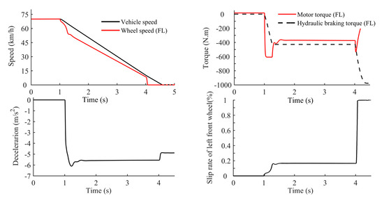
Figure 23.
Anti-lock brake control results under a wet asphalt pavement road.
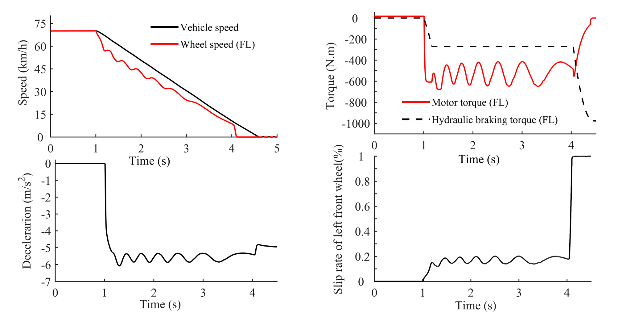
Figure 24 shows that the ABS control strategy proposed in this paper possesses a perfect robustness. The wheel slip rate can maintain at ideal value (approximately ) only by adjusting the motor torque, even if the road adhesion coefficient fluctuates within a small range.
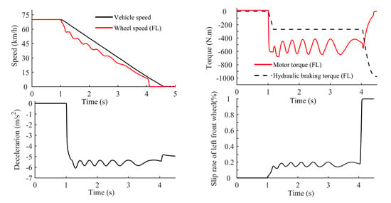
Figure 24.
Results of anti-lock control when the braking intensity varies between and .
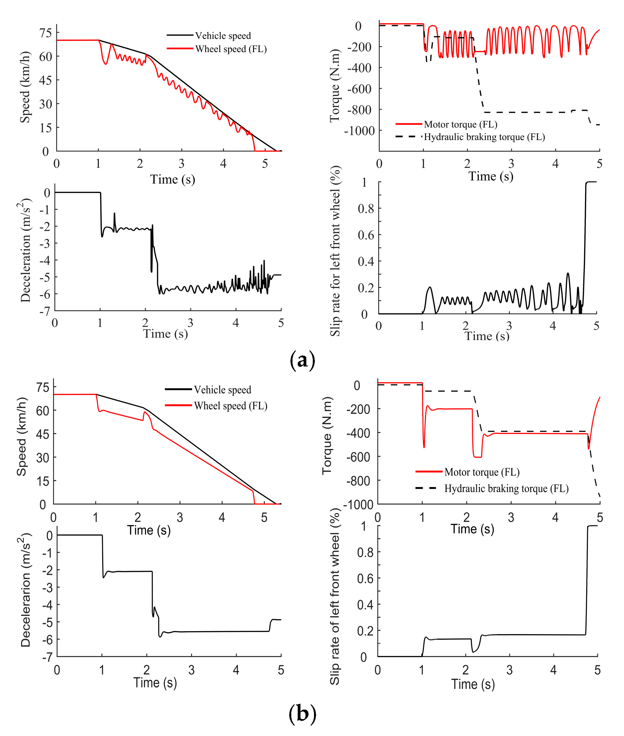
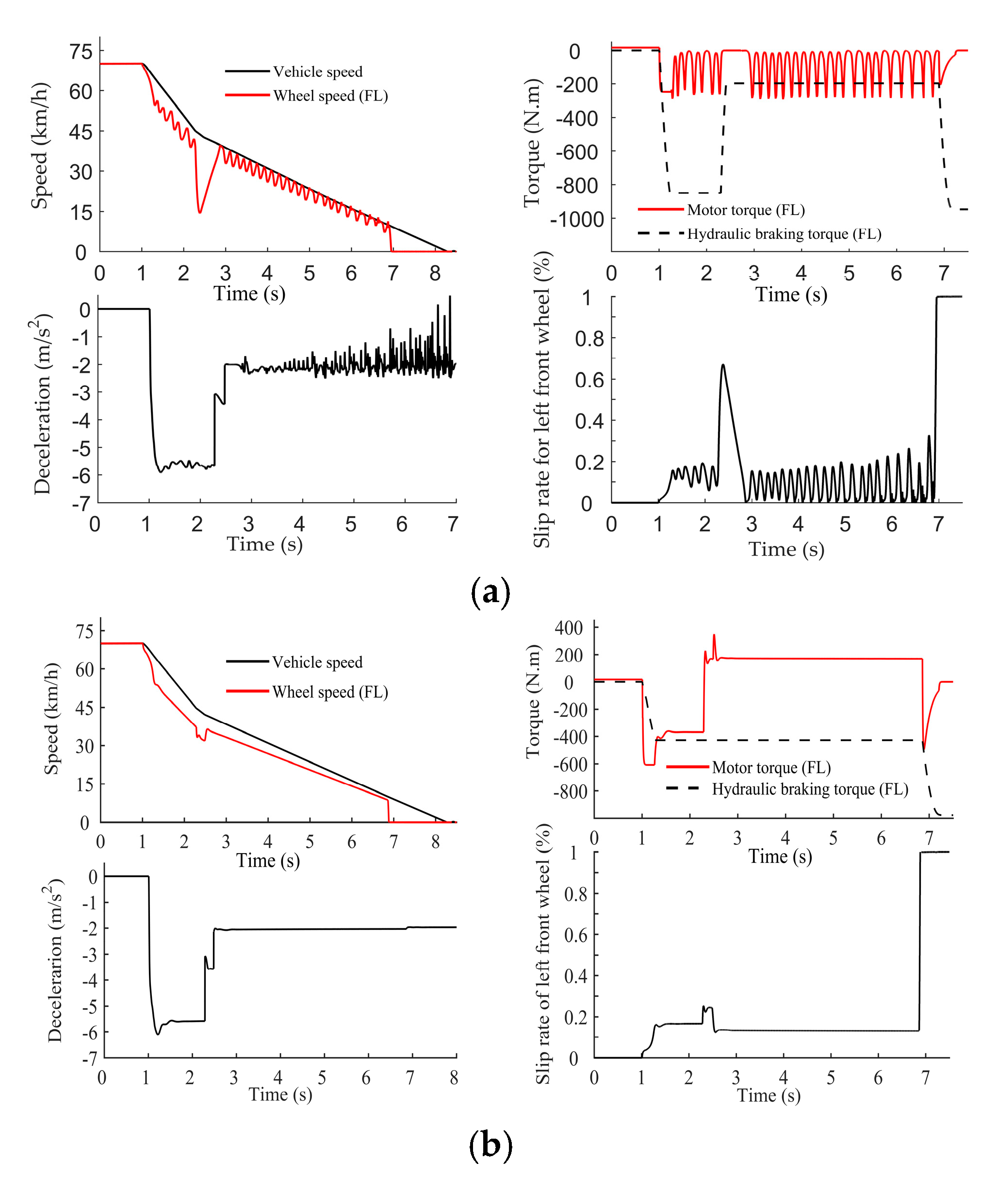
When a car leaves a snow-compacted road and enters a wet asphalt road, the initial braking speed is 70 km/h, the target braking intensity is selected as . The conventional ABS control strategy based on coordinated adjustment of the motor braking torque and the hydraulic braking is taken as a comparison. Simulation results are shown in Figure 25.
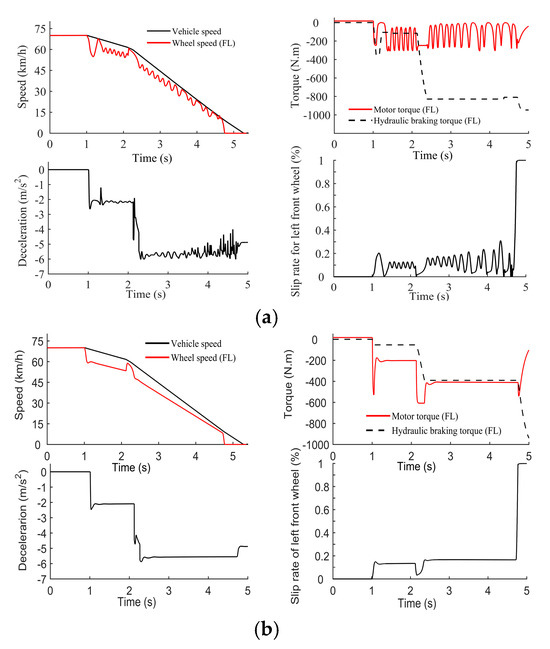
Figure 25.
The simulation results of ABS when driving from a compacted snow road to a wet asphalt road: (a) The ABS control strategy based on coordinated adjustment of the motor braking torque and the hydraulic braking torque; (b) The ABS control strategy based on pure motor torque adjustment.
By comparing Figure 25a,b, it can be found that ABS control method based on pure motor adjustment maintains a more stable slip rate, smoother motor torque change and avoids frequent closing of solenoid valves.
When the car leaves a wet asphalt road and enters a snow-compacted road, the simulation results are as follows Figure 26:
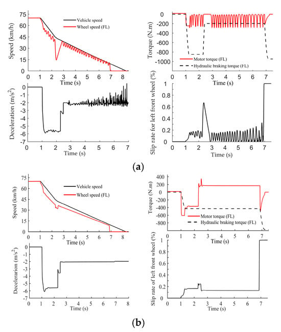
Figure 26.
The simulation results of the ABS when driving from a wet asphalt road to a compacted snow road: (a) The ABS control strategy based on coordinated adjustment of the motor braking torque and the hydraulic braking torque; (b) The ABS control strategy based on pure motor torque adjustment.
In summary, considering the results presented in Table 6, it can be concluded that the proposed strategy achieves high energy recovery efficiency under different braking intensities. Performance: The Electro-Hydraulic Coordinated strategy shows marginally better performance in terms of faster response (shorter settling time) and slightly lower overshoot on high-μ surfaces, attributable to the high power density of the hydraulic system for rapid torque adjustment.

Table 6.
Quantitative Comparison of ABS Control Strategies (Left Front Wheel, v0 = 70 km/h).
Efficiency: The Pure Motor Control strategy demonstrates a significant advantage in energy recovery, reclaiming over twice the energy (41.5 kJ vs. 18.2 kJ) on wet asphalt. This is because it utilizes the motor for all torque modulation during ABS, maximizing regeneration, whereas the coordinated strategy consumes energy hydraulically.
Low-μ & Transition Performance: The Pure Motor Control strategy effectively handles the challenging low-μ and transition scenarios, maintaining stable slip control with a high energy recovery rate (48.5 kJ), proving its robustness and efficiency across diverse conditions.
The proposed Pure Motor Control strategy, enabled by the novel HCU, presents a highly favorable trade-off, sacrificing minimal performance metrics to achieve a dramatic improvement in energy recovery efficiency and functional simplicity, making it particularly suitable for electric vehicles where range is paramount.
It can be found that the conventional ABS control method based on coordinated control of motor braking torque and hydraulic braking torque needs to judge the road condition changes and open the pressure-reducing valve to reduce hydraulic braking torque, while ABS control method based on pure motor only needs to adjust motor torque, which is more accurate and rapid.
5. Test of the Hydraulic Control System and a Real Vehicle
5.1. Hydraulic Control System Test
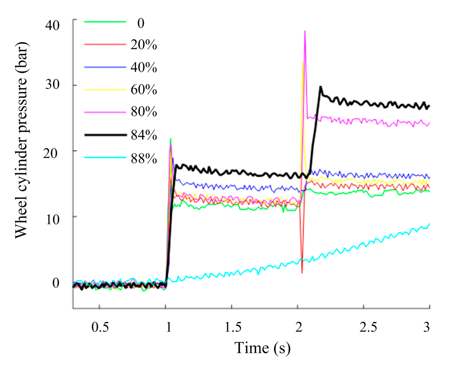
A HCU must possess the function that the wheel cylinder pressure can accurately follow the target hydraulic braking force. The test process is shown in Figure 4 and the duty cycle of the input signal is continuously changed. The test results are shown in Figure 27.
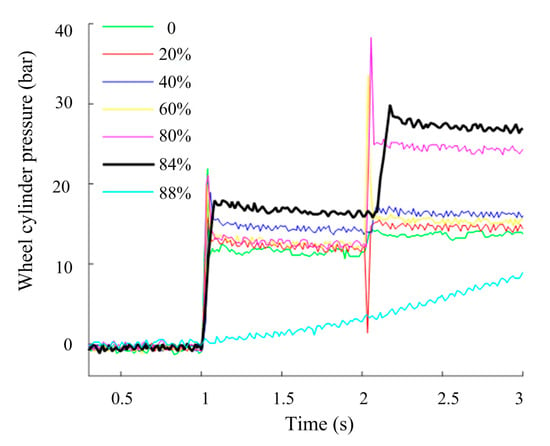
Figure 27.
Comparison of the different duty cycle input signals.
It is determined that when the duty cycle is 84%, the target tracking effect performs well.
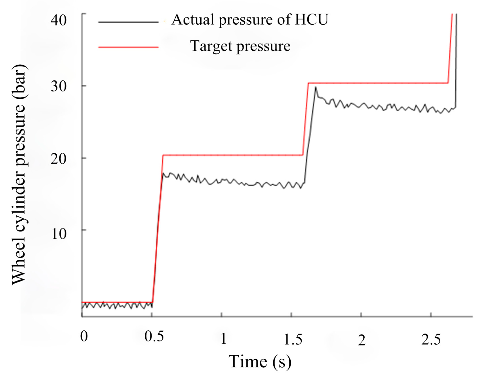
Figure 28 shows that when the duty cycle of the input control signal is selected as 84%, the actual wheel cylinder pressure can better follow the target pressure.
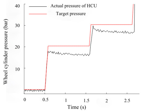
Figure 28.
Comparison between the true hydraulic control system pressure and the target pressure.
5.2. Real Vehicle Test
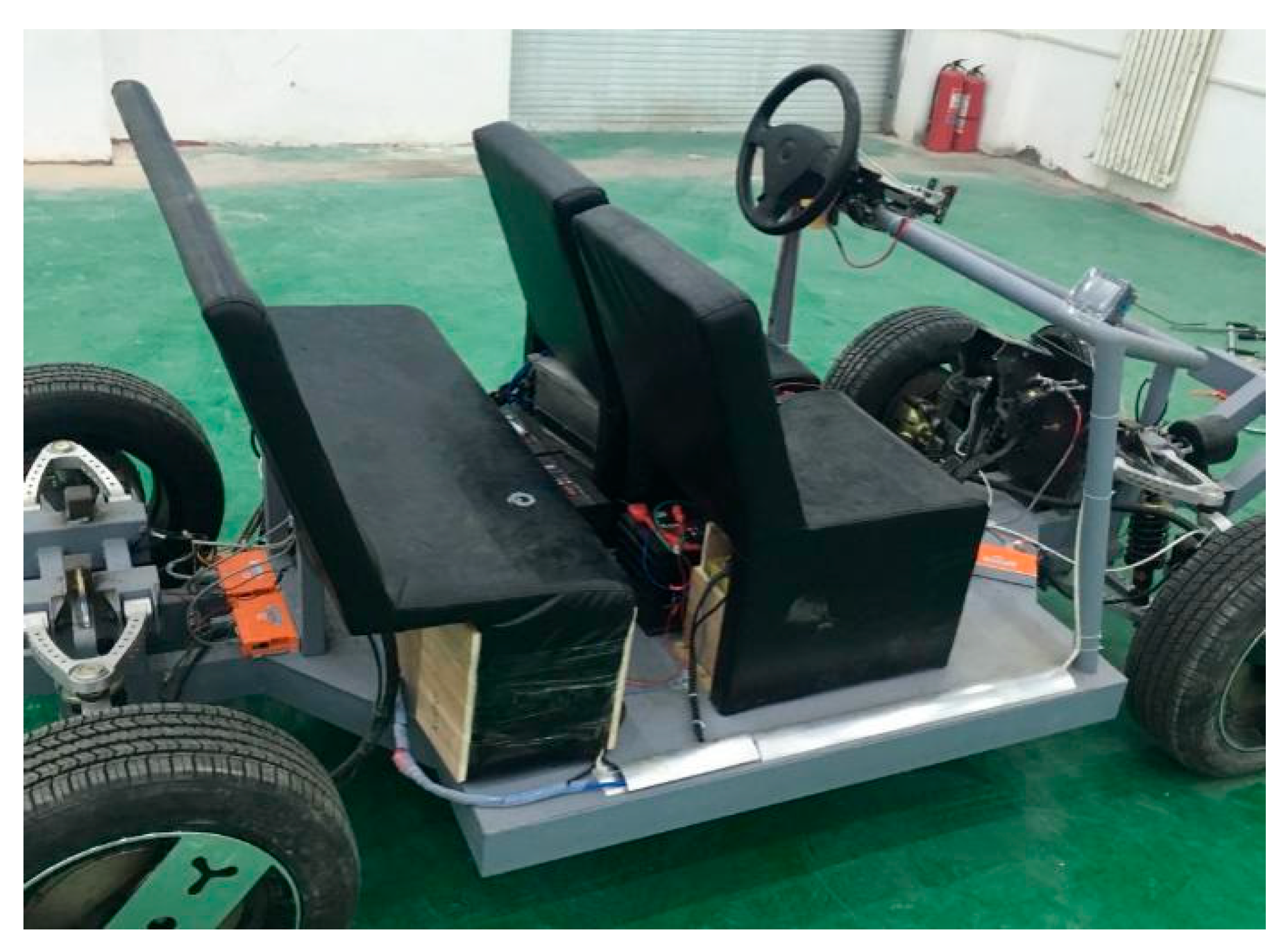
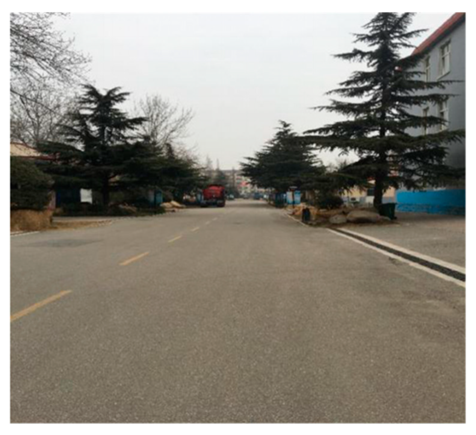
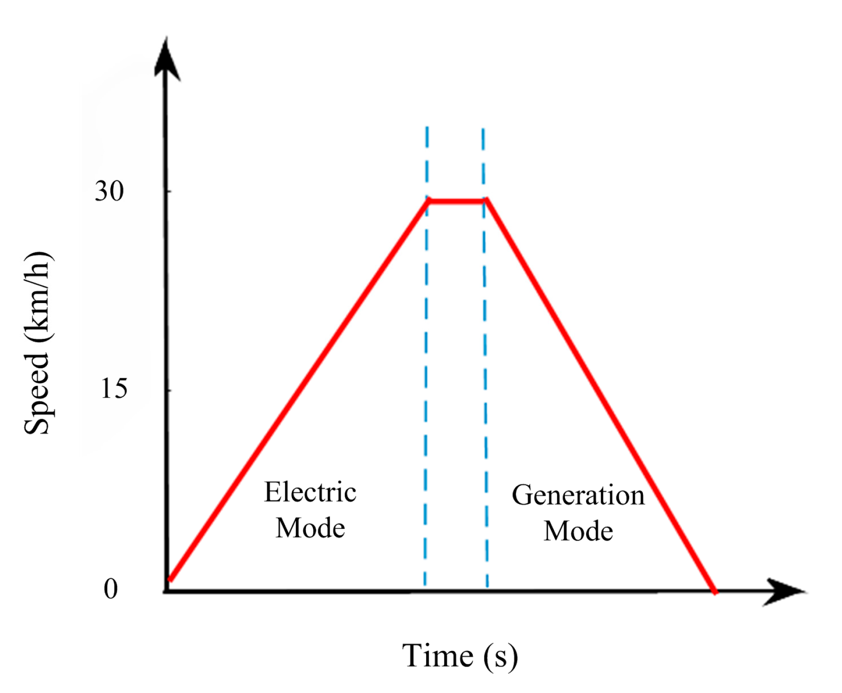
The test vehicle used in this paper is shown in Figure 29. The initial braking speed is selected as 30 km/h, and the test road is selected as dry asphalt pavement (high adhesion coefficient), as shown in Figure 30. During the real vehicle test, the pure motor regenerative braking mode is mainly tested. The test procedure is shown in Figure 31.
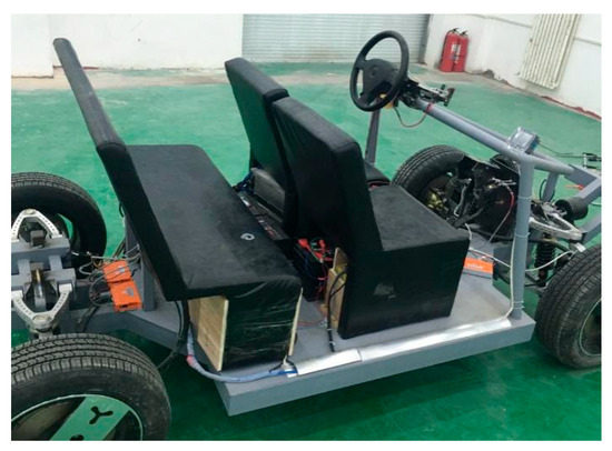
Figure 29.
Overall drawing of a real vehicle.
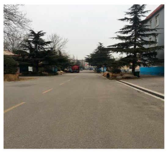
Figure 30.
The test road.
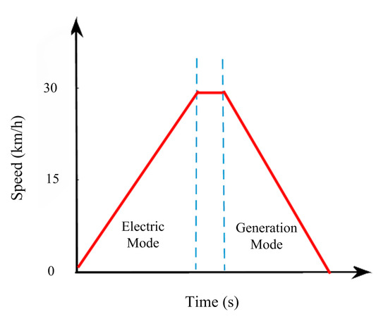
Figure 31.
The test process curve.
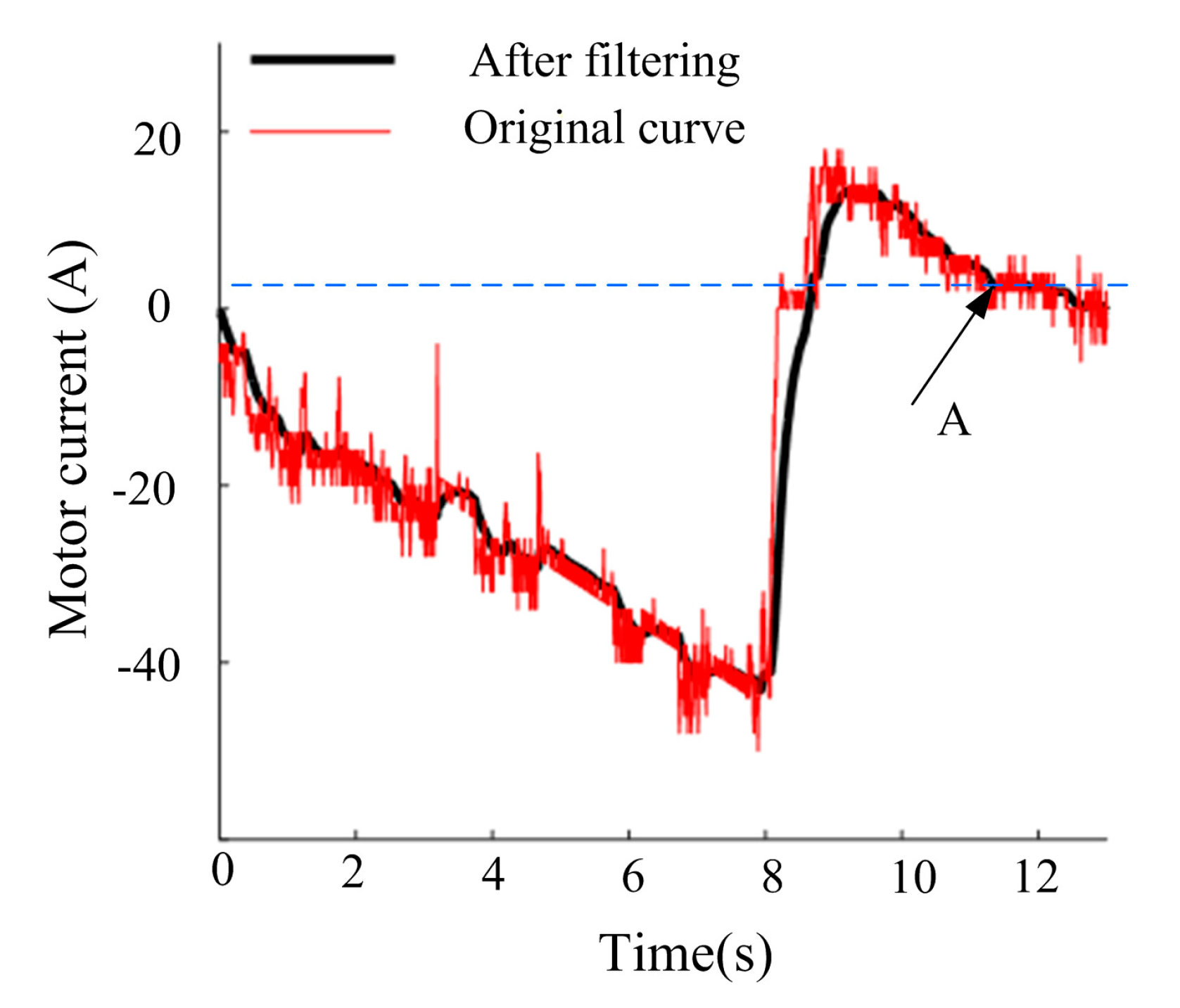
When the hub motor is in the motor mode, the current is negative, and it is in the state of power consumption. When it is in the power generation mode, the current is positive.
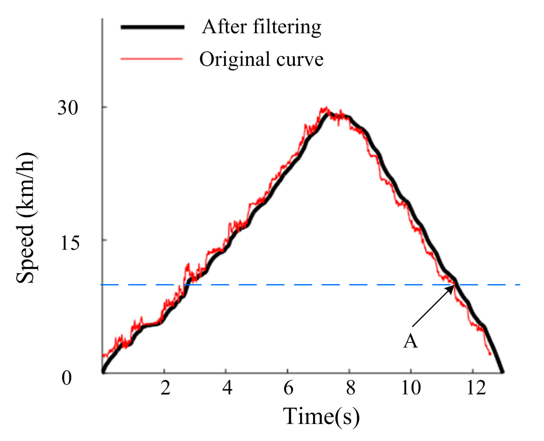
In this paper, the vehicle speed signal is calculated based on the four wheel speed signals, which fluctuate. The motor and current also exhibit large jumps. To better reflect the speed and motor current changes, it is necessary to filter them as follows:
where is the output value after filtering in the current cycle, is the measured value of the current cycle, is the output value after filtering in the previous cycle, and is the filtering coefficient.
In this study, a first-order low-pass filter is applied to process the vehicle speed and motor current signals, as expressed in Equation (26). The filter coefficient α determines the trade-off between noise suppression and dynamic response. A larger α results in smoother signals but introduces a lag that prevents accurate tracking of rapid changes, while a smaller α provides limited noise reduction. To evaluate the sensitivity of α, three representative values (α = 0.05, 0.1, and 0.2) were tested on the same vehicle speed and current signals. The results show that α = 0.05 insufficiently suppresses noise, whereas α = 0.2 causes excessive delay in reflecting signal dynamics. In contrast, α = 0.1 achieves a favorable balance between smoothness and responsiveness. Therefore, α = 0.1 was adopted in this paper for subsequent simulations and experiments.
Figure 32 and Figure 33 show that in the acceleration phase, with an increase in the vehicle speed, the current consumed by the motor increases continuously. When the speed is accelerated to 30 km/h, the motor is in the power generation state. Clearly, when the vehicle speed drops below 10 km/h (i.e., after point A), the current generated by the motor decreases to approximately 0. The motor no longer has power generation capacity and the motor heat loss is large.
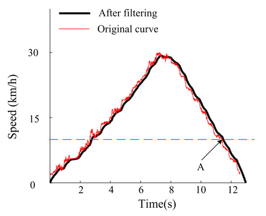
Figure 32.
Speed versus time.
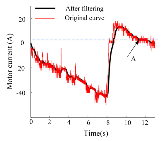
Figure 33.
Motor current versus time.
The results prove the rationality of entering the electro-hydraulic switching mode when 10 km/h. When 10 km/h, the in-wheel motor can better feedback current.
6. Conclusions and Future Work
This study proposed and validated a coordinated control strategy for the electro-hydraulic composite braking system of an in-wheel motor (IWM) electric vehicle using a joint Simulink–AMESim–CarSim platform and real-vehicle tests. Simulation and experimental results consistently demonstrated that the proposed strategy achieved target braking force, improved energy recovery efficiency, and maintained braking stability. However, discrepancies between simulation and real-vehicle results remain. These arise from actuator dynamics (e.g., hysteresis, friction, dead zones), sensor noise and delays, and uncontrollable variations in real road adhesion, especially under low-μ conditions. Furthermore, real-vehicle validation was limited to regenerative braking mode, without full coverage of composite braking and ABS on complex surfaces. While the joint simulation platform proved effective and repeatable for control strategy development, actuator nonlinearities and environmental uncertainties highlight the need for more comprehensive testing.
From these findings, several conclusions are drawn. First, a novel HCU without a pressure-reducing valve was developed, which enhances energy recovery efficiency and extends driving range through a simplified hydraulic design. Second, simulation results confirm that the proposed coordinated control strategy accurately tracks target braking intensity across varying adhesion levels, while the ABS strategy based solely on motor torque adjustment effectively stabilizes wheel slip within the optimal 13–17% range, reducing torque oscillations and valve switching events. Third, real-vehicle tests under low-speed conditions verified stable target braking force and smooth electro-hydraulic switching, confirming feasibility. The main limitation is insufficient validation of ABS under complex low-adhesion conditions.
Future work will focus on employing higher-power IWMs to extend the ABS adjustment range, conducting more systematic composite-mode real-vehicle experiments on low-adhesion surfaces, and integrating hardware-in-the-loop (HIL) and bench testing for higher-fidelity validation. Additionally, the proposed control framework will be extended toward global optimization between energy recovery and stability, while incorporating driver–vehicle interaction.
Author Contributions
Conceptualization, H.L. and L.J.; methodology, H.L. and J.L.; software, J.L.; validation, H.L., J.L., and F.X.; formal analysis, H.L.; investigation, F.X.; resources, F.X. and Z.W.; data curation, F.X. and G.Z.; writing—original draft preparation, H.L.; writing—review and editing, L.J. and Z.W.; visualization, G.Z.; supervision, L.J.; project administration, F.X.; funding acquisition, F.X. All authors have read and agreed to the published version of the manuscript.
Funding
This work was supported by Guangxi Science and Technology Major Program (Grant No. Guike AA23062067).
Data Availability Statement
The data presented in this study are available on request from the corresponding author. The data are not publicly available due to ongoing research.
Conflicts of Interest
Author Guangming Zhang was employed by the company SAIC Motor Corp. Technology Center, Shanghai. The remaining authors declare that the research was conducted in the absence of any commercial or financial relationships that could be construed as a potential conflict of interest.
References
- Yang, Y.; Wang, C.; Zhang, Q.; He, X. Torque Coordination Control during Braking Mode Switch for a Plug-in Hybrid Electric Vehicle. Energies 2017, 10, 1684. [Google Scholar] [CrossRef]
- Yang, Y. Research on New Electro-Hydraulic Compound Braking System for Pure Electric Vehicles. Master’s Thesis, Chongqing University, Chongqing, China, 2012. [Google Scholar]
- Song, S.X. Study on Control Strategy and HIL Experiment for Distributed Driving Electric Vehicle. Ph.D. Dissertation, Jilin University, Changchun, China, 2015. [Google Scholar]
- Naseri, F.; Farjah, E.; Ghanbari, T. An Efficient Regenerative Braking System Based on Battery/Supercapacitor for Electric, Hybrid, and Plug-In Hybrid Electric Vehicles with BLDC Motor. IEEE Trans. Veh. Technol. 2017, 66, 3724–3738. [Google Scholar] [CrossRef]
- Ko, J.; Ko, S.; Son, H.; Yoo, B.; Cheon, J.; Kim, H. Development of brake system and regenerative braking cooperative control algorithm for automatic-transmission-based hybrid electric vehicles. IEEE Trans. Veh. Technol. 2015, 64, 431–440. [Google Scholar] [CrossRef]
- Totev, V.; Gueorgiev, V. Efficiency of Regenerative Braking in Electric Vehicles. In Proceedings of the 2020 21st International Symposium on Electrical Apparatus & Technologies (SIELA), Bourgas, Bulgaria, 3–6 June 2020; pp. 1–4. [Google Scholar] [CrossRef]
- Xing, Y.; Lv, C. Dynamic State Estimation for the Advanced Brake System of Electric Vehicles by Using Deep Recurrent Neural Networks. IEEE Trans. Ind. Electron. 2020, 67, 9536–9547. [Google Scholar] [CrossRef]
- Fujimoto, H.; Harada, S. Model-Based Range Extension Control System for Electric Vehicles With Front and Rear Driving-Braking Force Distributions. IEEE Trans. Ind. Electron. 2015, 62, 3245–3254. [Google Scholar] [CrossRef]
- Lv, C.; Hu, X.; Sangiovanni-Vincentelli, A.; Li, Y.; Martinez, C.M.; Cao, D. Driving-Style-Based Codesign Optimization of an Automated Electric Vehicle: A Cyber-Physical System Approach. IEEE Trans. Ind. Electron. 2019, 66, 2965–2975. [Google Scholar] [CrossRef]
- Li, W.; Du, H.; Li, W. Four-Wheel Electric Braking System Configuration With New Braking Torque Distribution Strategy for Improving Energy Recovery Efficiency. IEEE Trans. Intell. Transp. Syst. 2019, 21, 87–103. [Google Scholar] [CrossRef]
- Li, B.; Du, H.; Li, W. A Potential Field Approach-Based Trajectory Control for Autonomous Electric Vehicles With In-Wheel Motors. IEEE Trans. Intell. Transp. Syst. 2017, 18, 2044–2055. [Google Scholar] [CrossRef]
- Yang, Y.; Luo, C.; Li, P. Design and performance analysis on a new electro-hydraulic hybrid transmission system. Int. J. Electr. Hybrid Veh. 2017, 9, 134–150. [Google Scholar] [CrossRef]
- Shi, J.; Wu, J.; Zhu, B.; Zhao, Y.; Deng, W.; Chen, X. Design of Anti-lock Braking System Based on Regenerative Braking for Distributed Drive Electric Vehicle. SAE Int. J. Passeng. Cars-Electron. Electr. Syst. 2018, 11, 205–218. [Google Scholar] [CrossRef]
- Ramakrishnan, R.; Hiremath, S.S.; Singaperumal, M. Design strategy for improving the energy efficiency in series hydraulic/electric synergy system. Energy 2014, 67, 422–434. [Google Scholar] [CrossRef]
- Nadeau, J.; Micheau, P.; Boisvert, M. Ideal regenerative braking torque in collaboration with hydraulic brake system. In Proceedings of the 2017 Twelfth International Conference on Ecological Vehicles and Renewable Energies (EVER), Monte Carlo, Monaco, 11–13 April 2017. [Google Scholar]
- Ma, Z.; Sun, D. Energy Recovery Strategy Based on Ideal Braking Force Distribution for Regenerative Braking System of a Four-Wheel Drive Electric Vehicle. IEEE Access 2020, 8, 136234–136242. [Google Scholar] [CrossRef]
- Lv, C.; Zhang, J.; Li, Y.; Yuan, Y. Directional-stability-aware brake blending control synthesis for over-actuated electric vehicles during straight-line deceleration. Mechatronics 2016, 38, 121–131. [Google Scholar] [CrossRef]
- Ko, J.W.; Ko, S.Y.; Kim, I.S.; Hyun, D.Y.; Kim, H.S. Co-operative control for regenerative braking and friction braking to increase energy recovery without wheel lock. Int. J. Automot. Technol. 2014, 15, 253–262. [Google Scholar] [CrossRef]
- Zhao, G.; Tang, J.; Sun, Q.; Li, L.; Zhao, X. An ABS control strategy for electric vehicles with regenerative braking priority. Mech. Sci. Technol. 2020, 39, 214–220. [Google Scholar]
- Lv, C. Dynamical Blending Control of Regenerative Braking and Frictional Braking for Electrified Vehicles. Ph.D. Dissertation, Tsinghua University, Beijing, China, 2015. [Google Scholar]
- Sun, F.; Liu, W.; He, H.; Guo, H. An integrated control strategy for the composite braking system of an electric vehicle with independently driven axles. Veh. Syst. Dyn. 2016, 54, 1031–1052. [Google Scholar] [CrossRef]
- Yang, Y.; He, Y.; Yang, Z.; Fu, C.; Cong, Z. Torque Coordination Control of an Electro-Hydraulic Composite Brake System During Mode Switching Based on Braking Intention. Energies 2020, 13, 2031. [Google Scholar] [CrossRef]
- Zhang, Z.; Zhang, J.; Sun, D.; Lv, C. Research on control strategy of electric-hydraulic hybrid anti-lock braking system of an electric passenger car. In Proceedings of the 2015 IEEE Intelligent Vehicles Symposium, Seoul, Republic of Korea, 28 June–1 July 2015. [Google Scholar]
- Wu, T.B. Research on Dynamic Coordinated Control Algorithm for Braking Force of Electric Vehicles. Master’s Thesis, Jilin University, Changchun, China, 2013. [Google Scholar]
- Heydari, S.; Fajri, P.; Sabzehgar, R.; Asrari, A. Optimal Brake Allocation in Electric Vehicles for Maximizing Energy Harvesting During Braking. IEEE Trans. Energy Convers. 2020, 35, 1806–1814. [Google Scholar] [CrossRef]
- Sun, D.; Lan, F.; Zhou, Y.; Chen, J. Control Algorithm of Electric Vehicle in Coasting Mode Based on Driving Feeling. Chin. J. Mech. Eng. 2015, 28, 486. [Google Scholar] [CrossRef]
- Ji, F.; Pan, Y.; Zhou, Y.; Du, F.; Zhang, Q.; Li, G. Energy recovery based on pedal situation for regenerative braking system of electric vehicle. Veh. Syst. Dyn. 2019, 58, 144–173. [Google Scholar] [CrossRef]
- Goto, Y. Next-Generation Environmentally Friendly Vehicles Development and Commercialization Project (3rd Stage) in Japan; Sae Technical Papers 3; SAE: Warrendale, PA, USA, 2013. [Google Scholar]
- Pacejka, H.B. Tire and Vehicle Dynamics, 2nd ed.; Butterworth-Heinemann: Oxford, UK, 2002. [Google Scholar]
- Rajamani, R. Vehicle Dynamics and Control, 2nd ed.; Springer: New York, NY, USA, 2012. [Google Scholar]
- Genta, G.; Morello, L. The Automotive Chassis: Volume 2: System Design; Springer: Berlin, Germany, 2009. [Google Scholar]
- Chen, J.-R.; Li, K.-Q. Research on control strategies of automotive anti-lock braking systems. Automot. Eng. 2004, 26, 429–432. [Google Scholar]
Disclaimer/Publisher’s Note: The statements, opinions and data contained in all publications are solely those of the individual author(s) and contributor(s) and not of MDPI and/or the editor(s). MDPI and/or the editor(s) disclaim responsibility for any injury to people or property resulting from any ideas, methods, instructions or products referred to in the content. |
© 2025 by the authors. Licensee MDPI, Basel, Switzerland. This article is an open access article distributed under the terms and conditions of the Creative Commons Attribution (CC BY) license (https://creativecommons.org/licenses/by/4.0/).

