Abstract
This paper proposes a distributed model predictive control (DMPC) framework integrating an event-triggered mechanism and an adaptive alternating direction method of multipliers (ADMM) to address the challenges of constrained computational resources and stringent real-time requirements in distributed vehicle platoon control systems. Firstly, the longitudinal dynamic model and communication topology of the vehicle platoon are established. Secondly, under the DMPC framework, a controller integrating residual-based adaptive ADMM and an event-triggered mechanism is designed. The adaptive ADMM dynamically adjusts the penalty parameter by leveraging residual information, which significantly accelerates the solving of the quadratic programming (QP) subproblems of DMPC and ensures the real-time performance of the control system. In order to reduce unnecessary solver invocations, the event-triggered mechanism is employed. Finally, numerical simulations verify that the proposed control strategy significantly reduces both the computation time per optimization and the cumulative optimization instances throughout the process. The proposed approach effectively alleviates the computational burden on onboard resources and enhances the real-time performance of vehicle platoon control.
1. Introduction
The increasing severity of traffic congestion and vehicle collisions in recent years has placed substantial pressure on modern transportation systems. To address these challenges, intelligent transportation systems (ITS) have been proposed, offering a unified framework that integrates autonomous driving technologies, vehicle-to-everything (V2X) wireless communications, and advanced computing into traffic management. This integration facilitates seamless interaction between vehicles-to-infrastructure (V2I) communication and vehicles-to-vehicles (V2V) communication, thereby enabling the formation of vehicle platoons that maintain desired inter-vehicle spacing and travel velocities.
Compared to traditional single-vehicle control strategies, the adoption of platoon-based control extends the optimization objective to the entire vehicle group. This holistic coordination allows for significantly reduced inter-vehicle gaps, leading to improved traffic throughput, enhanced longitudinal stability, and notable gains in overall energy efficiency for multi-vehicle systems [1,2,3].
Distributed model predictive control (DMPC) has emerged as a promising control strategy due to its capability to explicitly handle system constraints and address multi-objective optimization problems in a systematic manner. By leveraging future system predictions, DMPC enables comprehensive performance optimization over a receding horizon. As a result, it has been extensively investigated and applied in a wide range of domains, particularly in the cooperative control of vehicle platoons. Zheng et al. [4] established a four-element modeling framework for vehicle platoon control, comprising node dynamics, information flow topology, platoon geometric configuration, and distributed controllers. Concurrently, a distributed model predictive controller suitable for nonlinear heterogeneous platoons was designed. Zhang et al. [5] proposed a self-organizing cooperative control strategy, where merging vehicles form local platoons via a dynamic critical interval algorithm, and a DMPC framework coordinates their integration into the main formation. However, this approach still suffers from a high computational burden due to nonlinear modeling and DMPC optimization, relies on idealized assumptions such as homogeneity and perfect communication, and lacks sufficient validation under realistic conditions. Similarly, Hu et al. [6] proposed a distributed economic MPC strategy with switched feedback gains to improve fuel efficiency in vehicle platoons, and validated its stability and performance through theoretical analysis and simulations. However, the proposed EMPC strategy exhibits limitations in computational efficiency for real-time implementation, relies on idealized communication assumptions, and lacks comprehensive experimental validation under realistic disturbances and heterogeneous vehicle dynamics. Qiang et al. [7] proposed a DMPC scheme for heterogeneous vehicle platoons with inter-vehicle distance constraints. By adopting a parallel optimization framework with alternating updates between even- and odd-indexed vehicles and a tailored terminal inequality constraint, their approach overcomes key limitations of conventional methods, such as infeasibility in the absence of leader information, difficulty in maintaining spacing constraints, and limited adaptability to varying leader speeds. Pi et al. [8] further developed a DMPC-based energy-efficient strategy for electric platoons and integrated braking force distribution with energy recovery, which improved stability, tracking accuracy, and energy efficiency. Cen et al. [9] proposed a DMPC scheme for nonlinear platoon systems that employs a fused state estimator to mitigate missing state information caused by communication delays. However, the proposed framework relies on a linearized vehicle model and lacks a rigorous theoretical analysis of closed-loop and string stability under the combined effects of nonlinear dynamics, communication delays, and state estimation. Xu et al. [10] tackled critical challenges in highway multi-platoon cooperative control, namely poor system architecture scalability, low control accuracy under non-ideal communication conditions, and inadequate leader vehicle control adaptability in mixed traffic environments. Zhao et al. [11] and Zhao et al. [12] presented systematic cloud-based model predictive control schemes with novel delay compensation mechanisms, rigorously guaranteeing both asymptotic and string stability for vehicle platoons under heterogeneous communication delays, thereby enhancing tracking accuracy, fuel efficiency, and practical applicability. Wen et al. [13] proposed a novel linear control law for connected and automated vehicle platoons that incorporates a vehicle speed prediction model to effectively mitigate the detrimental effects of time-varying communication delays, thereby enhancing platoon stability and safety. Their solution comprises a system architecture combining static management with dynamic switching capability, alongside a delay-compensated DMPC method and a robust MPC strategy for the leader vehicle under disturbances from human-driven vehicles. While the aforementioned studies successfully employed DMPC to achieve effective control of vehicle platoon systems in their respective scenarios, the computational burden associated with solving the DMPC optimization problem becomes significant when considering complex vehicle dynamics characterized by coupled longitudinal-lateral nonlinearities. Consequently, there is a pressing need to investigate computationally efficient solution algorithms to ensure the real-time performance of cooperative platoon control.
The implementation of DMPC requires executing model predictions and solving receding horizon optimization problems at every sampling instant, which imposes a substantial computational burden on vehicle platoon systems. To address this issue, increasing attention has recently been directed toward event-triggered control mechanisms, which aim to reduce unnecessary computations by updating control actions only when certain state-dependent conditions are met. This paradigm offers the potential to alleviate resource consumption while maintaining satisfactory control performance. Zhao et al. [14] proposed an adaptive event-triggered safety control approach that dynamically adjusts the event-triggering threshold based on abrupt changes in the preceding vehicle’s behavior to optimize communication bandwidth utilization. By integrating an adaptive cost function and a controller gain optimization algorithm, the method ensures the strict string stability of vehicle platoons under limited bandwidth conditions, thereby enhancing both safety and control performance of the platoon. Luo et al. [15] proposed an event-triggered tube-based DMPC with a shrinking horizon and terminal region to ensure robustness under disturbances and delays. The triggering rule based on control plan variations reduces communication, but may not activate under large errors, posing safety risks. Han [16] proposed a bandwidth-aware scheduling strategy integrated with event-triggered DMPC to alleviate communication and computational load by dynamically adjusting triggering thresholds and optimization frequency. However, the proposed mechanisms lack practical implementation details for bandwidth state estimation, exhibit high parameter dependency, and insufficiently address robustness concerns under communication delays, packet losses, and potential event storms. Similarly, Selvaraj et al. [17] developed a memory-based event-triggered platooning control scheme that utilizes only position measurements and dynamic thresholds to improve communication efficiency while guaranteeing closed-loop stability through Lyapunov-based linear matrix inequality (LMI) formulations. Chen et al. [18] proposed an asynchronous self-triggered stochastic distributed MPC scheme that ensures probabilistic constraint satisfaction and quadratic stability for vehicle platoons under stochastic disturbances, while substantially reducing communication load in vehicular ad hoc networks. Du et al. [19] proposed a hierarchical dynamic event-triggered control protocol that guarantees zero-error tracking for heterogeneous vehicle platoons with actuator uncertainties and a nonzero-input leader, substantially reducing communication costs. However, the analysis and design are conducted under an ideal communication network assumption, leaving the system’s stability and performance vulnerable to practical network-induced imperfections such as communication delays and packet dropouts. Wang et al. [20] proposed a novel periodic event-triggered fault detection filter for vehicle platoons, which effectively saves communication resources while ensuring asymptotic stability and H∞ performance of the residual system under actuator faults and external disturbances. Although event-triggered mechanisms can effectively alleviate computational and communication burdens, their effectiveness may deteriorate in certain application scenarios.
A core advantage of the alternating direction method of multipliers (ADMM) in solving QP problems lies in its powerful decomposition capability. The algorithm decomposes complex problems into computationally tractable subproblems, allowing for parallel processing in large-scale applications. It is particularly effective at decoupling and handling complex constraints while maintaining high memory efficiency and ease of parallelization. Consequently, ADMM serves as a powerful framework for large-scale or structured quadratic programming. Li [21] proposed a heuristic adaptive ADMM approach for solving MPC problems, effectively enhancing the convergence rate of the algorithm. However, the adaptive parameters still require manual tuning, and improper settings may increase the convergence time. Tang [22] extended Li’s heuristic method to a multi-UAV simulation platform, demonstrating its potential and effectiveness for multi-agent systems and providing a novel approach for multi-agent coordinated control. Mallick et al. [23] developed a DMPC strategy based on a switching ADMM framework for piecewise affine (PWA) systems. This approach addresses the inherent nonconvex optimization problem by decomposing it into a sequence of convex subproblems. It concurrently coordinates the consensus of coupled states among subsystems, significantly reducing the computational burden while simultaneously ensuring closed-loop stability and recursive feasibility. Feng [24] addressed longitudinal-lateral coupling and tire nonlinearities using Koopman operator theory. They employed the ADMM to solve the resulting QP problem, achieving longitudinal tracking for vehicle platoons under complex driving conditions. Concurrently, Bai et al. [25] proposed a parallel DMPC framework based on ADMM, which effectively addresses the optimization problem with coupled safety constraints in cooperative control for connected automated vehicle (CAV) platooning, achieving both computational efficiency and robust safety guarantees. However, the framework lacks a thorough analysis of its convergence rate and computational scalability for large-scale platoons under real-world communication delays and dynamic topologies. However, within the aforementioned studies utilizing ADMM, investigations into its convergence properties remain limited. Furthermore, the design of adaptive parameters is often heavily reliant on domain expertise, and suboptimal parameter selection may fail to achieve peak performance.
The main contributions are summarized as follows.
- To overcome the excessive computation time associated with solving the core QP problem within traditional DMPC, which may result in delayed control actions and potential collisions, we design a residual-feedback-based adaptive ADMM algorithm. This algorithm dynamically adjusts the penalty parameter based on primal and dual residuals observed during the iterative process, thereby significantly enhancing computational efficiency within the control cycle.
- To further reduce the computational load of the control algorithm and conserve valuable onboard computing resources, an event-triggered mechanism is introduced. This mechanism departs from conventional time-triggered, fixed-period computation paradigms. Instead, the DMPC optimization is initiated only when the system state satisfies predefined triggering conditions.
2. Problem Formulation
2.1. Longitudinal Dynamic System of a Single Vehicle
In order to capture the essential characteristics of longitudinal vehicle motion, it is necessary to establish a nonlinear vehicle dynamics model that considers traction force, aerodynamic drag, and rolling resistance. Such a model provides a more realistic description of the vehicle’s motion compared with simplified kinematic representations and serves as the foundation for subsequent controller design. The nonlinear longitudinal dynamics of the vehicle can be formulated as follows:
where and are the position and velocity of vehicle ; and represent the actual and desired driving or braking torque, respectively; is the vehicle mass; is the tire radius; is the lumped air resistance coefficient; and are the mechanical efficiency and rolling resistance coefficient, respectively; is the gravity constant; is the time lag of the dynamic system.
To facilitate the analysis of vehicle dynamics, we adopt the feedback linearization technique, which has been widely employed in previous studies. The corresponding feedback strategy is expressed as follows:
Then, the nonlinear vehicle dynamics model is transformed into a third-order state-space model by applying feedback linearization method. The longitudinal dynamic model of vehicle , can be formulated as follows:
where , and denote the position, velocity, and acceleration of the vehicle , respectively, and represents the control input for the vehicle , which represents the desired acceleration. Defining the state vector for the vehicle at time as . The third-order state-space equation can be obtained as follows:
where , , .
Given that wireless communication inherently enables packet-based data transmission among vehicles, the use of sampled data is more suitable for system analysis and design. Therefore, a sampling period is defined, and the discrete-time longitudinal dynamics of the vehicle are derived using the forward Euler method. Moreover, the state error model is formulated as follows:
where , , , , .
The reference signal is directly determined by the adopted communication topology. Specifically, depending on the selected topology, it represents either the state of the leader vehicle or the state of the immediately preceding vehicle.
2.2. Communication Topology
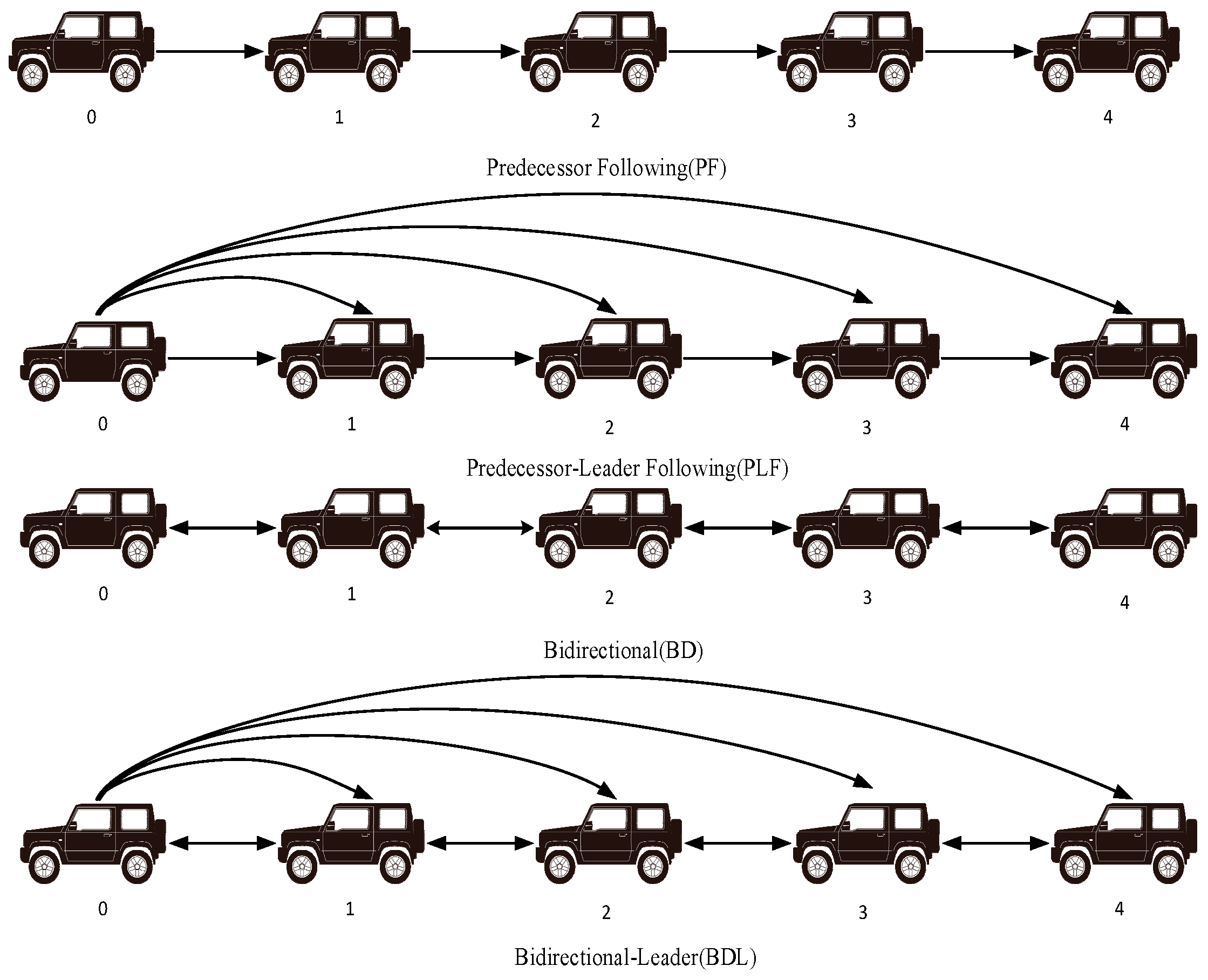
In the cooperative control of vehicle platoons, the information flow topology is crucial for determining system stability and coordination performance. This study utilizes concepts from algebraic graph theory to characterize the information flow among vehicles. The communication topology of the vehicle platoon is modeled as a directed graph , where denotes the set of vehicles and represents the set of directed communication links. Different information flow topologies have a significant impact on the design of the local objective functions for individual vehicles. Several prevalent communication topologies are illustrated in Figure 1.
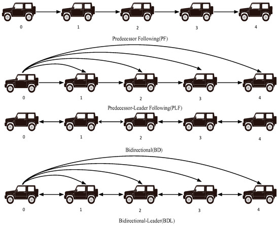
Figure 1.
Common Topological Configurations in Vehicle Platooning.
Within the platoon, vehicle 0 denotes the leading vehicle, while vehicles 1 to 4 represent the following vehicles. In principle, the proposed event-triggered DMPC framework can be extended to above topologies with minor modifications in the coupling terms of the cost function and the constraint set.
2.3. Formation Objective
The primary objective of vehicle platooning control is to achieve consensus among vehicles. Consensus refers to the ability of follower vehicles to synchronize their velocity and acceleration with the leader. Meanwhile, each vehicle should maintain a desired inter-vehicle spacing with its adjacent vehicles. The formation objective of platoon control can be defined as follows:
where denotes the actual velocity of the leader vehicle. Within the proposed framework, the leader is not subject to control; rather, its velocity is manually specified and broadcast to the follower vehicles through the adopted communication topology. This predefined velocity acts as the external input that governs the platoon dynamics. denotes the desired distance between the vehicle and its immediate predecessor. The choice of significantly influences the geometric configuration of the vehicle platoon. Common platoon geometries include constant spacing, constant time headway, and nonlinear spacing policies. In this study, a constant spacing policy is adopted to enhance the traffic throughput of the platoon:
where denotes a constant.
3. Adaptive ADMM-Based Event-Triggered Distributed Model Predictive Control
3.1. Prediction Model
The predictive model estimates future system states over a finite prediction horizon, utilizing the current state and historical data. For the convenience of controller design, we further construct the augmented variable , , Equation (5) can be obtained as follows:
where , , . Here, m = 1 and n = 3 denote the dimensions of the control input and the vector state vector, respectively. directly reflects the tracking error with respect to the designated reference vehicle, since contains the error state . Hence, minimizing in the cost function is equivalent to minimizing the tracking error.
In the DMPC scheme, the prediction horizon and control horizon are typically denoted as and , respectively. Assuming that the state variable of vehicle at time step is represented by , the following prediction equation can be derived based on Equation (8):
where , , , .
3.2. Design of the Cost Function
Building upon the previously described vehicle platoon model, a cost function is defined for each vehicle by incorporating its current state as well as the states of neighboring and leading vehicles. To ensure feasible and stable control performance while avoiding infeasibility issues, a slack variable is introduced, which guarantees the existence of a feasible solution at each control step. Then, the objective function is designed as follows:
where represents the weight matrix associated with the tracking performance, represents the weighting matrix penalizing the variation in control inputs, and denotes the desired reference trajectory.
The formulated cost function can be transformed into a standard QP problem for optimization. However, traditional QP solvers such as interior-point methods and active-set methods often fail to satisfy the real-time computational requirements of large-scale, multi-controller systems like vehicle platoons. Therefore, a more efficient optimization approach is required to enable fast and accurate tracking of the leader vehicle by multiple follower vehicles.
3.3. Residual-Based Adaptive ADMM Algorithm
The ADMM is a robust optimization framework that decomposes centralized control problems into smaller subproblems, enabling parallel solutions. It is particularly effective for distributed convex optimization, progressively converging to a globally optimal or acceptable locally optimal solution through iterative updates. ADMM has demonstrated strong performance in solving large-scale constrained optimization problems. It is typically applied to problems formulated in the following standard form:
where and represent convex functions, and are the variables to be optimized, and denotes the equality constraints to be satisfied.
By introducing the dual variable , the augmented Lagrange function corresponding to Equation (12) is constructed as follows:
In a typical ADMM framework, the iterative process involves successive updates of the primal variables and , the dual variable and the penalty parameter . To reduce computational complexity and facilitate implementation, the dual variable is often replaced by its scaled form, , leading to the following update rules.
During the iterative process, the primal variables and are updated alternately, which contributes to improved computational efficiency and faster convergence.
Existing adaptive ADMM algorithms typically employ heuristic ratio-based rules to adjust the penalty parameter adaptively at each iteration, based on intermediate solutions. However, as a generalization of the standard ADMM, the performance of such ratio-adaptive ADMM methods is highly sensitive to the proper selection of tuning parameters, which are usually specified through prior calibration by expert users. Improper selection of these adaptive parameters by non-expert users may significantly degrade the convergence speed. To address this limitation, this section proposes a residual-ratio-based adaptive ADMM method, which dynamically adjusts the relative magnitudes of the primal and dual residuals. This enables automatic parameter tuning and accelerates convergence, without requiring any user-defined parameters.
In distributed optimization problems, the primal residual represents the violation of the consensus constraints, while the dual residual reflects the convergence behavior of the dual variables. Traditional ADMM employs a fixed penalty parameter , which may lead to an imbalance between these two types of residuals. Specifically, a large tends to reduce the primal residual but significantly increases the dual residual, potentially causing oscillations when . Conversely, a small results in a large primal residual and a small dual residual. The exit condition of the algorithm depends on the primal and dual residuals. Throughout the convergence process, it is crucial to ensure that both residuals remain sufficiently small to accelerate convergence and improve overall efficiency.
The algorithm is considered to have converged when both the primal and dual residuals satisfy the following conditions:
where , .
Accordingly, a dynamic balancing criterion is established as follows:
To enhance algorithm robustness, the penalty parameter is adaptively adjusted to maintain the primal and dual residuals within the same order of magnitude. Based on the dynamic balancing criterion, a normalized residual ratio is introduced. Specifically, the normalized residual ratio between the primal and dual residuals is defined, and the corresponding expression can be formulated as follows:
where , denote the initial primal and dual residuals, respectively.
The adaptive penalty parameter update rule, based on the geometric mean principle, is formulated as follows:
The geometric mean principle ensures that the proposed adaptive rule maintains a balance between global search and local convergence. Specifically, when , the penalty parameter is increased to enforce constraint satisfaction, while it is decreased to mitigate oscillations when the dual residual dominates.
Meanwhile, to ensure the continuity of the Lagrange multiplier , the dual variables are scaled synchronously as follows:
The cost function described in Equation (9) is reformulated into a QP form, which is expressed as follows:
where , , , , .
Based on the derived standard QP formulation for the longitudinal tracking control problem of the vehicle platoon, dual variables are introduced to reformulate the problem into the canonical ADMM form. The resulting ADMM formulation is given as follows:
where , and is the indicator function. defined as .
Based on the Lagrange multiplier method and the preceding ADMM formulation, the augmented Lagrange function is given as follows:
Based on Equation (11), the scaled dual variable is introduced. Then, by combining the first-order optimality conditions for the primal variable and the auxiliary variable , the iterative update rules are derived as follows:
To enhance the convergence rate and computational efficiency of the ADMM algorithm, a relaxation parameter is introduced. Additionally, the solution from the previous iteration is leveraged in the update process to accelerate subsequent iterations. The modified update equations are given as follows:
The computational complexity of the proposed ADMM-MPC algorithm is dominated by the -update, which involves solving a linear system. Let the decision variable dimension be . Each iteration of ADMM requires operations, and the total complexity is , where is the number of iterations. Compared to classical active-set methods (ASM) and interior-point methods (IPM), ADMM exhibits a similar per-iteration cost but typically converges with fewer iterations in practice, particularly when warm-start strategies are employed.
Extending to the distributed case with vehicles, each vehicle solves its local QP of dimension at every iteration. The total computational complexity of the multi-vehicle system is therefore .
3.4. Design of Event-Triggered Mechanism
In the development of cooperative control systems for vehicle platoons, the traditional time-triggered mechanism was initially applicable in the early stages when in-vehicle networks were relatively underdeveloped. However, with the evolution of intelligent transportation systems towards large-scale and dynamic deployments, the limitations of time-triggered mechanisms have become more apparent. Specifically, their rigid resource utilization leads to unnecessary computation and communication even when the platoon is in a steady cruising state or the tracking error has converged within an acceptable tolerance, thereby resulting in wasted computational resources.
In contrast, the event-triggered mechanism effectively addresses the trade-off between limited computational resources and control timeliness by transitioning from a time-driven to a state-driven paradigm. It has demonstrated significant advantages in reducing resource consumption, lowering computation frequency, and maintaining system stability. Specifically, within the framework of DMPC, where the controller performs receding horizon optimization to generate the optimal control sequence, the triggering condition is defined as follows:
where denotes the control input at the time step , and represents the most recent triggering instant. The position and velocity components of the output are selected to formulate the triggering condition:
The parameter serves as a triggering threshold, which is used to regulate the triggering frequency. When , the event-triggered mechanism reduces to the conventional time-triggered scheme. As increases, the triggering frequency decreases accordingly.
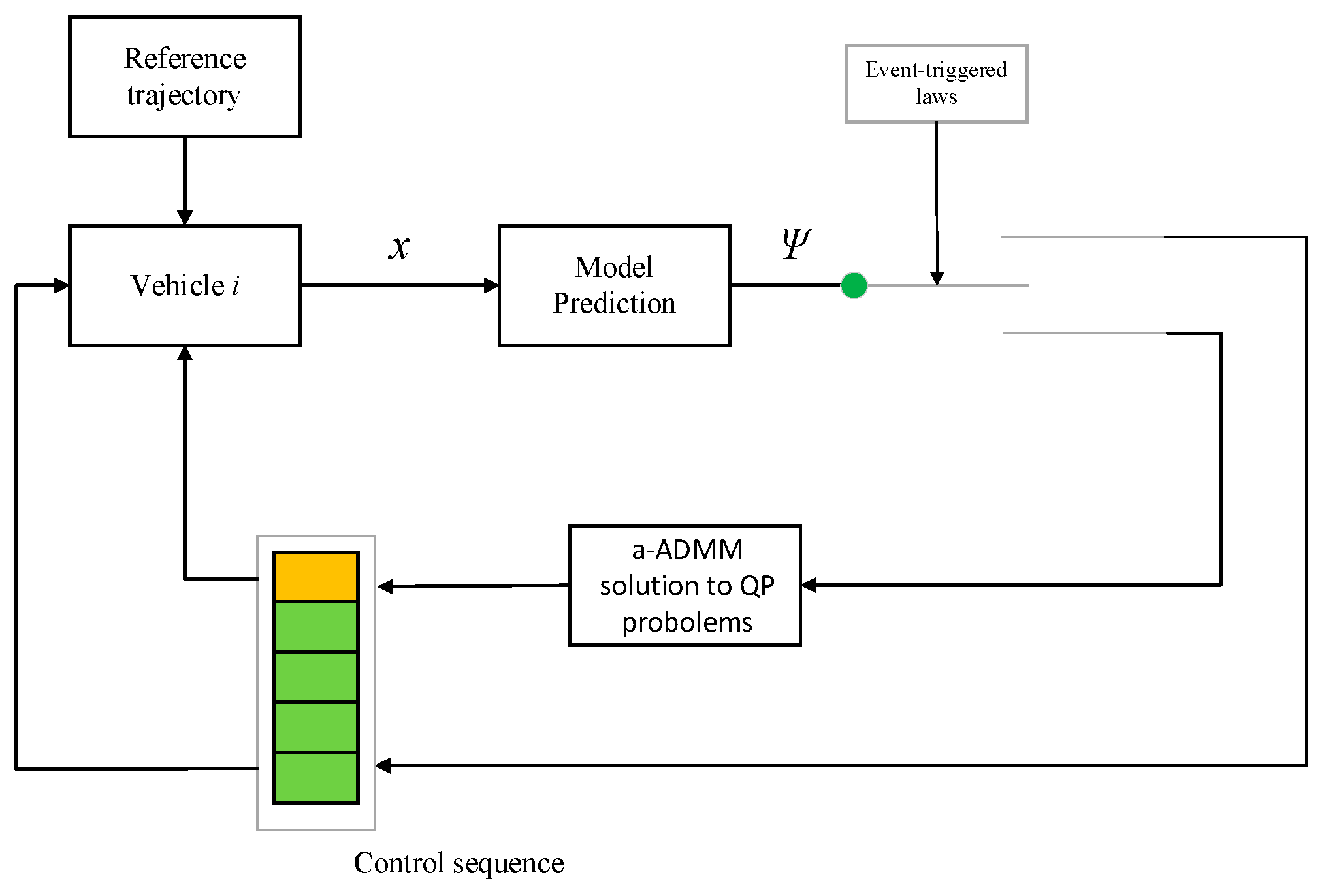
Following the description of the core algorithmic components, the overall workflow of the proposed event-triggered adaptive ADMM-DMPC framework is illustrated in Figure 2.
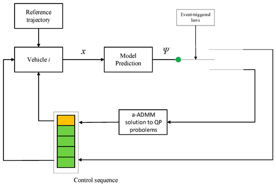
Figure 2.
Framework of the Event-triggered and Adaptive ADMM-based DMPC for Vehicle Platoon.
The system accepts a reference trajectory as input, while the event-triggered mechanism determines when local optimization should be executed. Each vehicle formulates and solves its local QP using the a-ADMM algorithm in coordination with its neighbors. This workflow highlights the closed-loop integration from trajectory planning to distributed control execution.
To further clarify the real-time operation of the event-triggered DMPC scheme, the detailed algorithmic steps at each sampling instant are summarized as follows:
- Check the event-triggering condition (24). If the triggering condition is satisfied, each vehicle initiates the distributed ADMM-based DMPC optimization; otherwise, the vehicles directly reuse the previously computed optimal control sequence and apply the control input corresponding to the current sampling instant, then proceed to step 8.
- For each vehicle, formulate the local quadratic programming problem by expressing the objective function in the form of (10) according to its own state-space model and the coupling constraints imposed by the communication topology.
- Reformulate (10) into the decomposed form suitable for ADMM optimization (cf. Equation (20)).
- Initialize the ADMM solver with the optimal solutions obtained at time
- Update the primal and dual variables iteratively according to the distributed ADMM updating rules, as given in (23).
- Adaptively update the penalty parameter based on the normalized residual ratio (16) and the update rule (17), so as to dynamically balance the primal and dual residuals and enhance convergence speed.
- Check the termination criteria (14). If satisfied, terminate the iteration and transmit the control input corresponding to the current sampling instant from the optimized sequence of each vehicle to the platoon system; otherwise, continue the distributed iteration until the maximum number of iterations is reached.
- Advance to the next sampling instant and repeat step 1.
4. Asymptotic Stability
To establish the stability of the vehicle platoon, the cost function is commonly employed as a Lyapunov candidate. Nevertheless, under the event-triggered mechanism, the optimization problem is not solved at every discrete sampling instant, which prevents the monotonic decrease in the Lyapunov function from being directly ensured.
Theorem 1.
The following theorem provides conditions to ensure the Lyapunov stability of the system (8).
Supposed that:
- there exists a stabilizing terminal feedback such that is Schur;
- there exists a positive definite matrix satisfying the discrete-time Lyapunov inequality.
Then, for sufficiently large
, the platoon is asymptotically stable.
Proof of Theorem 1.
We define the collective Lyapunov function:
where contains the error state , .
- Substituting Equation (8) into , we obtain:where .
From Equation (26), the first term satisfies:
Thus,
By Young’s inequality, for any , the second term satisfies:
By applying Young’s inequality to , we obtain an upper bound involving only quadratic terms in and . Also, the third term satisfies .
Thus,
where .
The prediction error evolves as follows:
where . Hence,
Substituting into Equation (32):
where .
If , then . Choosing
Ensures for some .
Thus,
Since , we obtain
Then, for sufficiently large satisfying the (36), decreases strictly unless all and the closed-loop vehicle platoon is asymptotically stable. □
5. Simulation and Result Analysis
To verify the effectiveness of the proposed controller, simulation experiments are carried out in MATLABR2022a/Simulink. A platoon of five intelligent connected autonomous vehicles is considered, consisting of 1 leading vehicle and 4 following vehicles. The predecessor-following (PF) topology is adopted as the communication structure. The parameter settings for the cost function are summarized in Table 1.

Table 1.
Parameter Settings of the Cost Function for the DMPC.
A total simulation time of 30 s was considered, with a sampling period of T = 0.05 s, leading to 600 sampled data points for each vehicle state.
5.1. Scenario-Based Validation
5.1.1. Disturbance Scenario
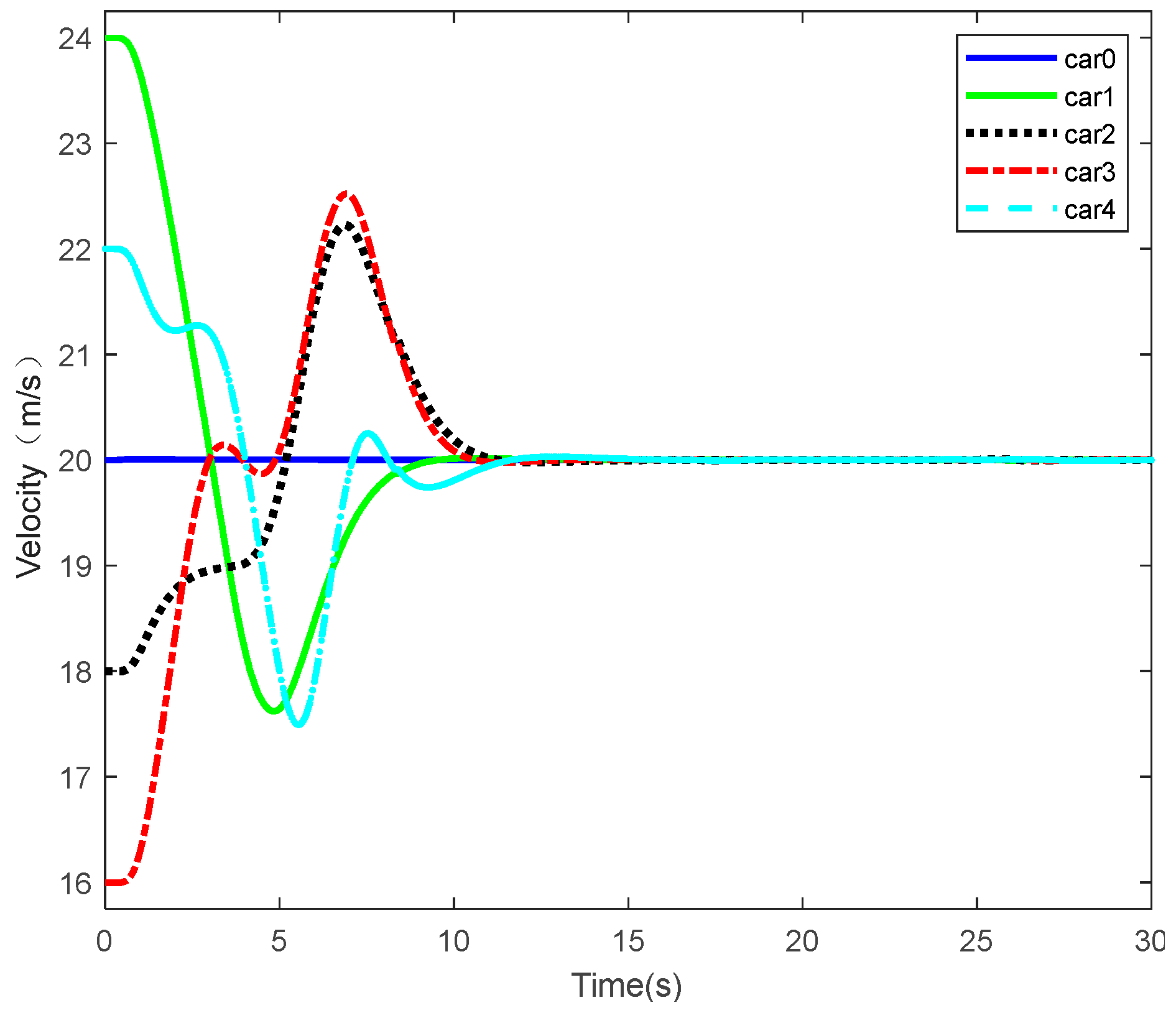
The disturbance scenario is designed to assess whether vehicles are initially operating from different states. The objective is to determine if they can converge to the desired states specified by the leading vehicle under the proposed controller. The corresponding simulation results are illustrated in Figure 3.
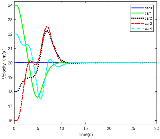
Figure 3.
The speed trajectories of each vehicle under the disturbance scenario.
Figure 3 illustrates the platoon configuration, where Car 0 denotes the leader vehicle and Cars 1–4 denote the follower vehicles. The leader vehicle is not equipped with a controller; instead, its velocity profile is predefined and transmitted to the followers through the communication topology. In the disturbance scenario, the leader vehicle maintains a constant velocity of 20 m/s, which is transmitted to the followers through the communication topology. The initial speeds of the following vehicles (ordered front to rear) are set to 24 m/s, 18 m/s, 16 m/s, and 22 m/s, respectively. This heterogeneous configuration places the system in an unstable initial condition. Nevertheless, the simulation result demonstrates that the following vehicles, controlled by the proposed controller, rapidly converge to the steady state. They achieve consensus with the leader vehicle’s speed, matching the desired state. The simulation result robustly validates the designed controller’s capability to stabilize the system despite significant initial internal instability. Furthermore, it satisfies the requirements for Lyapunov stability and consensus theory.
5.1.2. Acceleration Scenario
Acceleration represents one of the most fundamental and frequently encountered driving maneuvers in real-world traffic scenarios. Consequently, validating the performance of autonomous vehicle platoon systems under acceleration scenarios is essential.
To this end, we define the following reference velocity signal to verify the platoon’s behavior during acceleration.
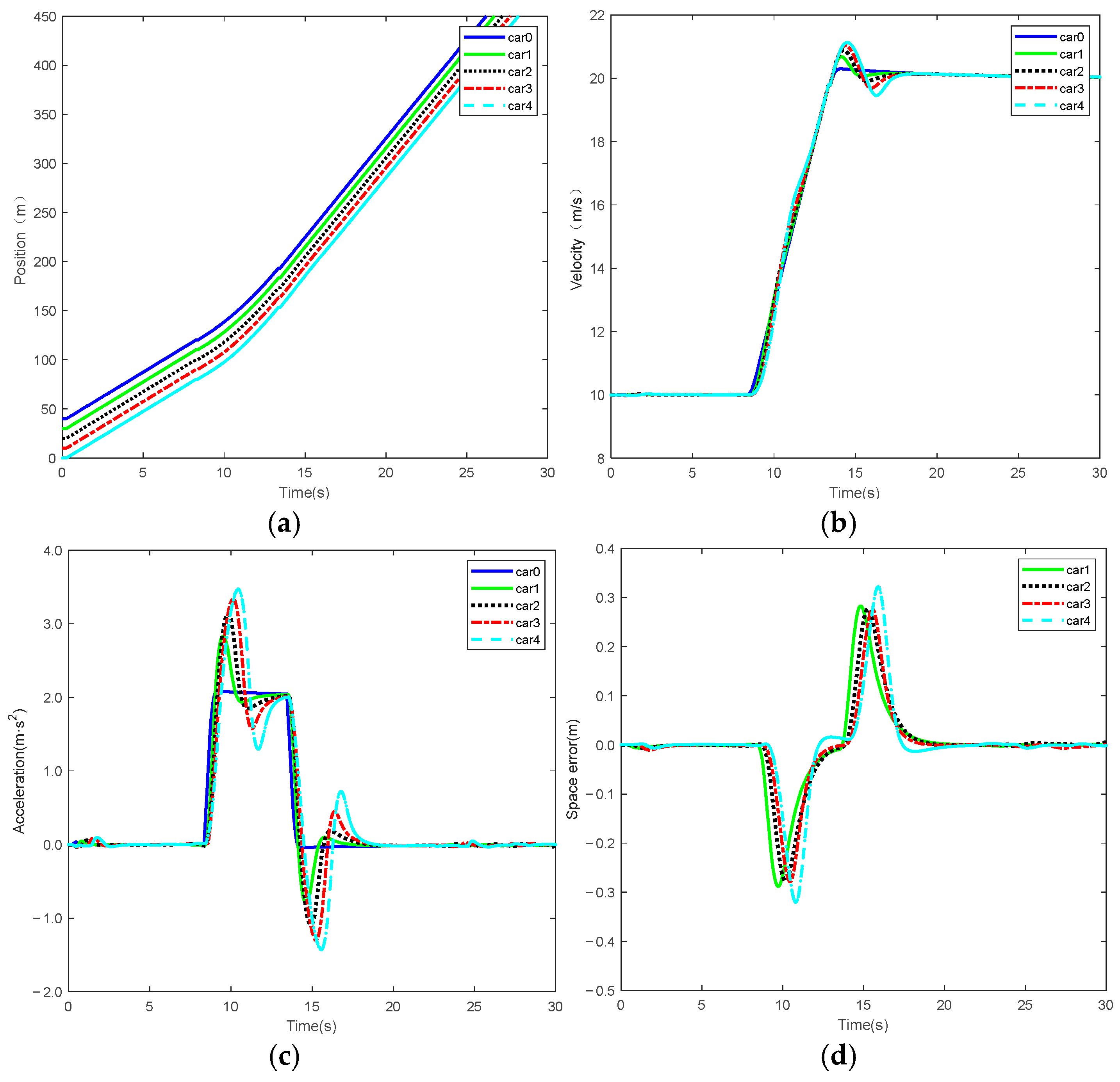
At the commencement of the simulation, all leading and following vehicles within the platoon possess identical initial velocities and exhibit zero position errors. The corresponding simulation results are presented in Figure 4.
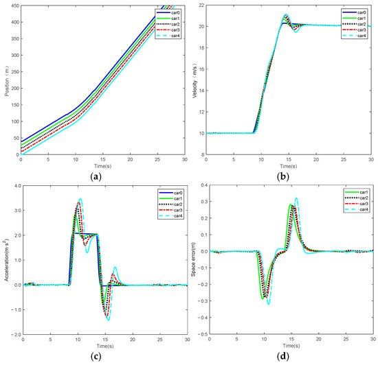
Figure 4.
State trajectories of individual vehicles under accelerating scenario. (a) Position state trajectories; (b) velocity state trajectories; (c) acceleration state trajectories; (d) spacing error trajectories.
Figure 4 shows longitudinal position, velocity, acceleration and space error of vehicle platoon. Where Figure 4a shows that the position of each vehicle exhibits linear growth over time with parallel trajectories, indicating stable inter-vehicle spacing and well-maintained formation. Figure 4b,c show that the velocity and acceleration states of the following vehicles effectively synchronize with variations in the leading vehicle, reflecting coordinated velocity consensus. Regarding space error, Figure 4d shows that the initial error for all vehicles approximates zero. Transient fluctuations are observed during acceleration, subsequently converging to a stable state, confirming the high stability of the overall platoon formation.
5.1.3. Deceleration Scenario
Validating deceleration maneuvers within vehicle platoons is crucial for ensuring road traffic safety and traffic flow stability. Verification under such scenarios ensures the accuracy of coordinated responses across the platoon.
To this end, we define the following reference velocity signal to verify the platoon’s behavior during deceleration.
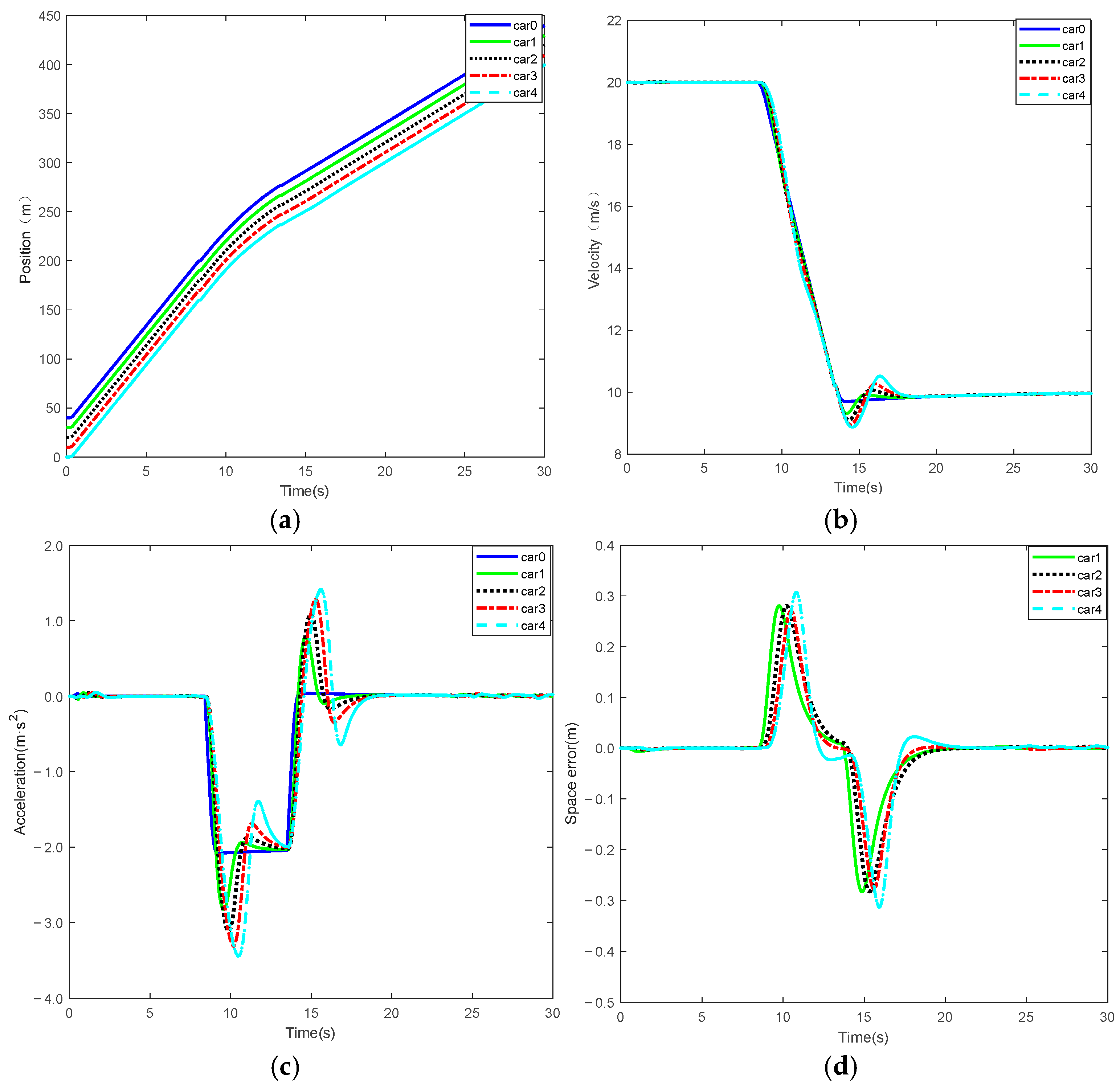
The simulation results of the developed vehicle platooning system under the proposed DMPC controller are presented in Figure 5.
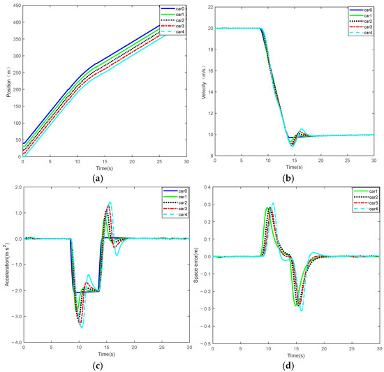
Figure 5.
State trajectories of individual vehicles under decelerating scenario. (a) Position state trajectories; (b) velocity state trajectories; (c) acceleration state trajectories; (d) spacing error trajectories.
Figure 5 illustrates the longitudinal position, velocity, acceleration, and space error of the vehicle platoon under deceleration scenarios. Where Figure 5a shows that the position trajectories of all vehicles remain parallel during the deceleration process, indicating stable inter-vehicle spacing and consistent maintenance of the desired following distance, with no risk of collision. Figure 5b,c demonstrate that the velocity and acceleration profiles of the following vehicles rapidly adapt to the state changes in the leading vehicle, reflecting effective coordination and disturbance rejection within the platoon. Regarding space error, Figure 5d shows that the position errors-measured relative to the leader-exhibit only brief transient deviations during deceleration and quickly converge to a narrow bound, signifying high-precision tracking and strong formation stability. Collectively, the platoon demonstrates synchronized velocity profiles, consistent acceleration patterns, smooth progression of inter-vehicle spacing with constant distance, and well-regulated position errors. These results collectively verify the effectiveness of the proposed control algorithm in enhancing safety and preserving platoon coherence under deceleration conditions.
5.2. Comparison
Based on the simulation results under the aforementioned three scenarios, the proposed DMPC controller achieves comparable tracking performance across all follower vehicles. For clarity and conciseness of comparison, a representative follower vehicle is selected to conduct detailed performance analysis.
5.2.1. Comparison of Triggering Strategies
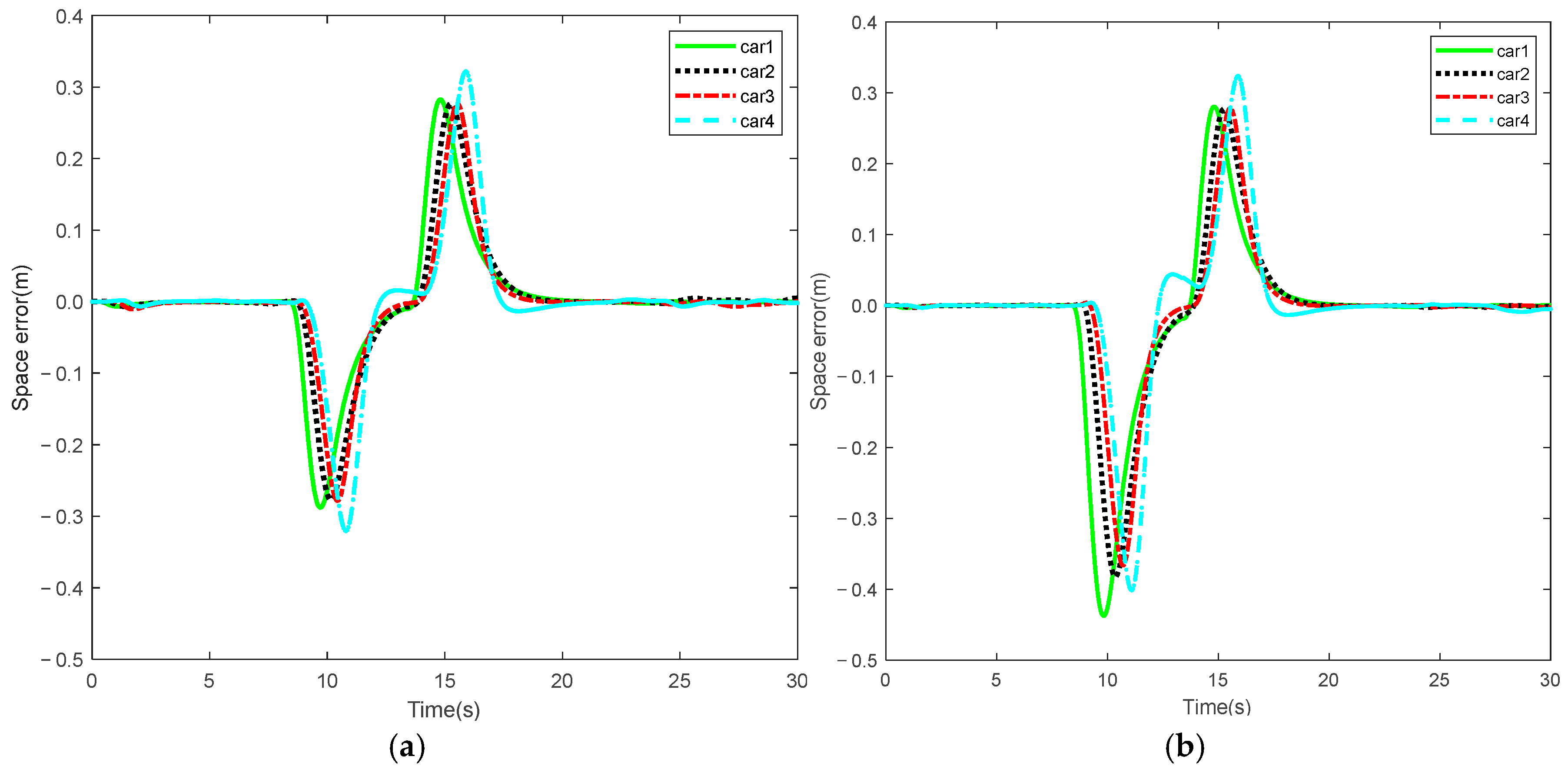
To validate the effectiveness of the proposed event-triggered mechanism in reducing computational burden while ensuring tracking accuracy, the position errors of the vehicles are illustrated in Figure 6 and compared with those obtained using the velocity-based triggering strategy presented in [16].
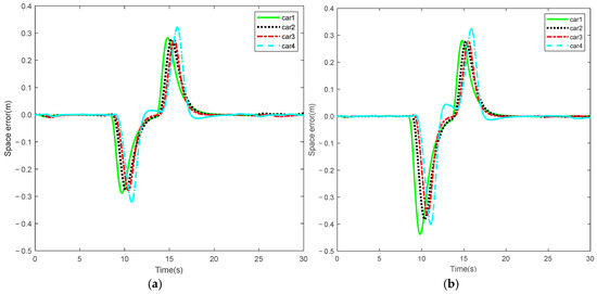
Figure 6.
Comparison of tracking accuracy under two event-triggered mechanisms. (a) Space error under the position–velocity trigger; (b) space error under the velocity-based trigger [16].
Compared with the event-triggered strategy presented in [16], the proposed mechanism yields smaller error fluctuations during vehicle operation. This indicates that the proposed approach offers improved control precision and effectively mitigates the growth of position errors.
The corresponding quantitative evaluation results are summarized in Table 2, which presents tracking accuracy metrics under both triggering strategies.

Table 2.
Comparison of tracking accuracy parameters for two event-triggered mechanisms.
The simulation results demonstrate that the proposed event-triggered mechanism reduces the average position error by 17.5% and the maximum position error by 26.6%, compared to the velocity-based triggering strategy presented in [16], thereby verifying its effectiveness in suppressing tracking errors. Overall, the proposed position–velocity event-triggered mechanism achieves significant improvements in both average and maximum position errors over the single-variable velocity-based approach.
In addition, the proposed event-triggered mechanism also demonstrates advantages in reducing computational burden. A comparison of the triggering counts for the two event-triggered schemes during simulation is provided in Table 3.

Table 3.
Comparison of triggering counts for two event-triggered mechanisms.
As shown in Table 3, the proposed event-triggered mechanism significantly reduces the number of triggering events compared with the strategy presented in [16]. Specifically, the proposed method yields 382 triggering counts during the simulation, whereas the method in [16] triggers 482 times, representing a reduction of approximately 20.7%. This result indicates that the proposed mechanism effectively decreases the triggering frequency, thereby reducing both computational burdens.
5.2.2. Performance Comparison of ADMM Variants
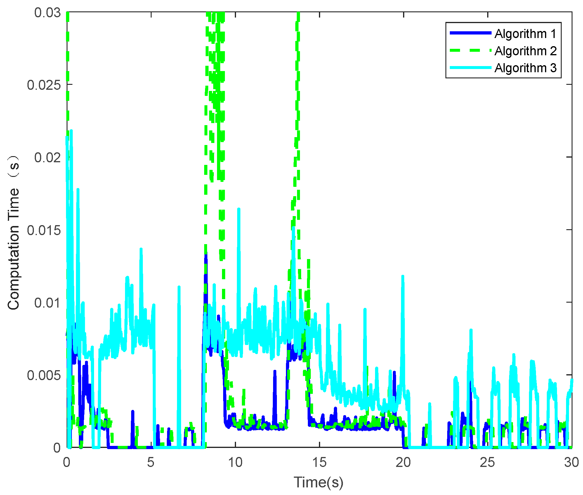
As demonstrated in [26], the ADMM-based approach achieves significantly better real-time performance in solving quadratic programming problems compared to classical IPM and ASM. Therefore, these two traditional methods are excluded from the comparison. A qualitative analysis is first conducted by recording the computation time of each ADMM variant at every sampling instant, and the results are visualized in Figure 7.
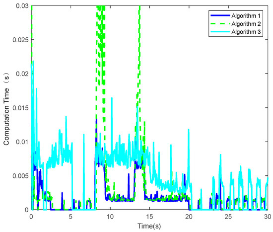
Figure 7.
Comparison of computational time among the three ADMM.
Algorithm 1 represents Proposed ADMM in this article.
Algorithm 2 represents Heuristic ADMM in [21].
Algorithm 3 represents ADMM in [26].
Subsequently, a quantitative analysis is performed by comparing two performance metrics: the maximum and average computation times, as summarized in Table 4.

Table 4.
Comparison of computational time among the three ADMM.
A cross-reference comparison of computation time results reported in [21,26] demonstrates that the ADMM-based method proposed in this study offers substantial improvements in computational efficiency. Specifically, the proposed method achieves a reduction of approximately 30.4% and 62.8% in average computation time compared to the methods in [21] and [26], respectively. In addition, the maximum computation time is also lower, with reductions of about 65.8% and 38.1% relative to [21] and [26], respectively.
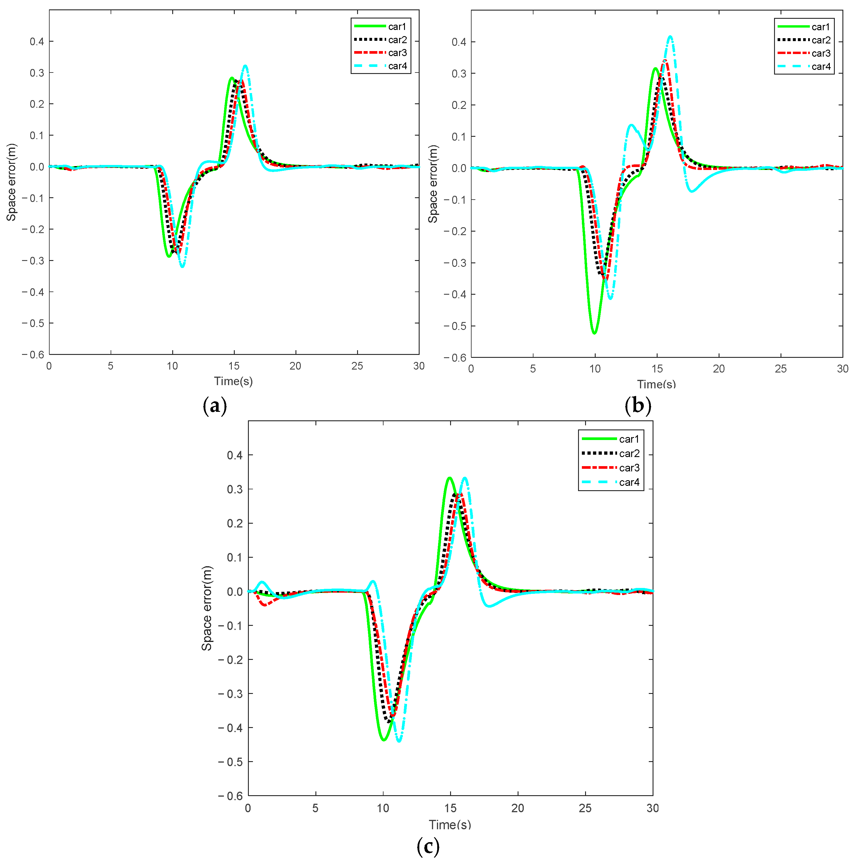
To validate the superiority of the proposed adaptive ADMM algorithm, a comparison of tracking accuracy was conducted against two other ADMM variants under identical standardized simulation scenario. The corresponding results are illustrated in Figure 8.
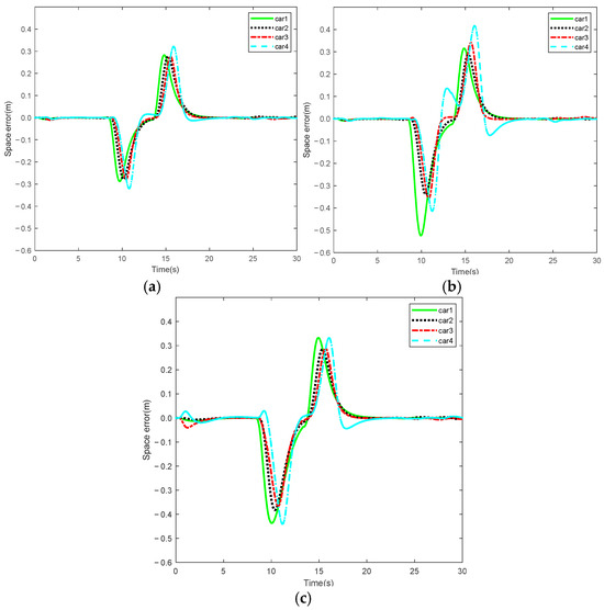
Figure 8.
Comparison of tracking accuracy under three ADMM. (a) Space error under the proposed ADMM; (b) space error under the heuristic ADMM in [21]; (c) space error under the ADMM in [26].
As illustrated in Figure 8, the proposed adaptive ADMM algorithm achieves a significantly lower space error compared to the other two ADMM algorithms under identical coordinate scales. Subsequently, a quantitative comparison is performed by comparing two evaluation metrics: average and maximum position errors, as presented in Table 5.

Table 5.
Comparison of tracking accuracy parameters for three ADMM.
As shown in Table 5, the proposed ADMM method achieves a clear advantage in terms of position error. Specifically, the average position error achieved by the proposed approach is 0.033 m, which is significantly lower than the results of 0.047 m and 0.049 m reported in [21,26], corresponding to reductions of approximately 29.8% and 32.7%, respectively. Moreover, the maximum position error is also reduced, with a value of 0.321 m compared to 0.524 m in [21] and 0.440 m in [26], representing reductions of around 38.7% and 27%, respectively. These results demonstrate the effectiveness of the proposed method in limiting maximum tracking errors.
Remark 1.
The simulation results under other topology configurations exhibit similar behavior to those of the predecessor-following (PF) structure and lead to the same conclusions. For brevity, the results for these additional topologies are not included in the paper.
The above results demonstrate that the proposed ADMM method effectively improves positioning accuracy by reducing the maximum tracking error and mitigating error fluctuations, thereby enhancing overall system stability and reliability. In summary, under road-driving scenarios with stringent real-time requirements, the proposed residual-based adaptive ADMM method significantly reduces computation time while improving tracking accuracy. These advantages contribute to enhanced driving safety and system stability, providing a reliable foundation for real-time vehicle control applications.
Moreover, the proposed event-triggered DMPC scheme demonstrates robustness across disturbance, acceleration, and deceleration scenarios, where the position errors consistently converge to zero, validating its capability to cope with dynamic driving conditions. From a computational perspective, each vehicle only solves a local QP through the a-ADMM decomposition, leading to moderate iteration counts (approximately 10–20 per step) and real-time feasibility. Simulations with varying fleet sizes further indicate that the average computation and communication burden per vehicle increases approximately linearly, thereby confirming the scalability of the distributed architecture. Future work will focus on extending the analysis to communication delays, packet losses, and larger-scale fleets.
6. Conclusions
This paper addresses the critical challenges of limited onboard computational resources and stringent real-time control requirements in DMPC-based vehicle platoon systems by presenting an event-triggered adaptive ADMM-DMPC framework. A longitudinal vehicle dynamics model and a communication topology are established to facilitate the implementation of the proposed control strategy under the DMPC scheme. Specifically, a residual-based adaptive ADMM algorithm is developed, which dynamically adjusts the penalty parameter based on residual scaling. This significantly accelerates the solution of quadratic programming subproblems in DMPC, thereby ensuring real-time performance. Moreover, the proposed adaptive ADMM method enhances tracking accuracy and improves overall control quality. A dual-state event-triggering mechanism is designed, where optimization is triggered only when position or velocity states exceed predefined thresholds. This substantially reduces unnecessary computations and alleviates computational burden during the control process. The proposed strategy is thoroughly validated through numerical simulations.
To validate the effectiveness of the proposed method, we established a simulation platform within the Matlab/Simulink environment and conducted system simulations. Compared with the velocity-based triggering strategy in [16], the event-triggered mechanism reduces the average error, maximum error, and triggering frequency by 17.5%, 26.6%, and 20.7%, respectively. The ADMM-based distributed optimization further demonstrates improved computational efficiency, with reductions in average computation time of 30.4% and 62.8%, and reductions in maximum computation time of 65.8% and 38.1%, relative to [21,26]. In terms of tracking accuracy, the proposed approach achieves average and maximum errors of 0.033 m and 0.321 m, corresponding to improvements of up to 32.7% and 38.7% over existing methods. These results indicate that the method significantly reduces both the computational time per optimization step and the total number of optimizations performed, effectively mitigating computational demands on vehicle-side processors and markedly improving the real-time performance of cooperative vehicle platooning.
For future work, it is of interest to implement the proposed algorithm in cloud computing, which contributes to further saving onboard computational resources. Furthermore, this study does not consider the coupled lateral and longitudinal control, and it is promising to extend the proposed algorithm to the combined horizontal and longitudinal control of vehicle platoons.
Author Contributions
Conceptualization, J.W.; formal analysis, H.Y.; data curation, W.L.; writing—original draft preparation, H.Z.; writing—review and editing, H.Z.; supervision, H.Y. and X.Z.; funding acquisition, H.Y. All authors have read and agreed to the published version of the manuscript.
Funding
This research was funded by the Guangxi Key Laboratory of Automobile Components and Vehicle Technology (2023GKLACVTZZ07).
Data Availability Statement
Not applicable.
Acknowledgments
The authors would like to thank the editor and reviewers for providing valuable review comments.
Conflicts of Interest
The authors declare no conflicts of interest.
References
- Agbaje, P.; Anjum, A.; Mitra, A.; Oseghale, E.; Bloom, G.; Olufowobi, H. Survey of Interoperability Challenges in the Internet of Vehicles. IEEE Trans. Intell. Transp. Syst. 2022, 23, 22838–22861. [Google Scholar] [CrossRef]
- Li, S.B.; Zheng, Y.; Li, K.Q.; Wu, Y. Dynamical Modeling and Distributed Control of Connected and Automated Vehicles: Challenges and Opportunities. IEEE Intell. Transp. Syst. Mag. 2017, 9, 46–58. [Google Scholar] [CrossRef]
- Wu, C.; Cai, Z.; He, Y.; Lu, X. A Review of Vehicle Group Intelligence in a Connected Environment. IEEE Trans. Intell. Veh. 2024, 9, 1865–1889. [Google Scholar] [CrossRef]
- Zheng, Y.; Li, S.E.; Li, K.; Borrelli, F.; Hedrick, J.K. Distributed model predictive control for heterogeneous vehicle platoons under unidirectional topologies. IEEE Trans. Control Syst. Technol. 2017, 25, 899–910. [Google Scholar] [CrossRef]
- Zhang, M.; Wang, C.; Zhao, W.; Liu, J.; Zhang, Z. A Multi-Vehicle Self-Organized Cooperative Control Strategy for Platoon Formation in Connected Environment. IEEE Trans. Intell. Transp. Syst. 2025, 26, 4002–4018. [Google Scholar] [CrossRef]
- Hu, M.; Li, C.; Bian, Y.; Zhang, H.; Qin, Z.; Xu, B. Fuel Economy-Oriented Vehicle Platoon Control Using Economic Model Predictive Control. IEEE Trans. Intell. Transp. Syst. 2022, 23, 20836–20849. [Google Scholar] [CrossRef]
- Qiang, Z.; Dai, L.; Chen, B.; Xia, Y. Distributed Model Predictive Control for Heterogeneous Vehicle Platoon With Inter-Vehicular Spacing Constraints. IEEE Trans. Intell. Transp. Syst. 2023, 24, 3339–3351. [Google Scholar] [CrossRef]
- Pi, D.; Xue, P.; Xie, B.; Wang, H.; Tang, X. A Platoon Control Method Based on DMPC for Connected Energy-Saving Electric Vehicles. IEEE Trans. Transp. Electrific. 2022, 8, 3219–3235. [Google Scholar] [CrossRef]
- Cen, S.; Bai, Z.; Wang, J.; Luo, X.; Li, X.; Fang, X.; Yuan, H. Distributed MPC for nonlinear networked vehicle platoon system with communication delays. In Proceedings of the 2024 China Automation Congress (CAC), Qingdao, China, 2–3 November 2024; pp. 1576–1581. [Google Scholar]
- Xu, M.; Luo, Y.; Yang, G.; Kong, W.; Li, K. Dynamic Cooperative Automated Lane-Change Maneuver Based on Minimum Safety Spacing Model. In Proceedings of the 2019 IEEE Intelligent Transportation Systems Conference (ITSC), Auckland, New Zealand, 27–30 October 2019; pp. 1537–1544. [Google Scholar]
- Zhao, J.; Ma, Y.; Dai, L.; Sun, Z.; Chen, H.; Xia, Y. Distributed Cloud Model Predictive Control With Delay Compensation for Heterogeneous Vehicle Platoons. IEEE Trans. Veh. Technol. 2025, 74, 11793–11805. [Google Scholar] [CrossRef]
- Zhao, F.; Li, H.; Wang, J.; Li, J. String Stability Based Cloud Predictive Control of Vehicle Platoon With Random Time Delay. IEEE Trans. Veh. Technol. 2025, 74, 8784–8796. [Google Scholar] [CrossRef]
- Wen, J.; Wang, S.; Dai, M.; Lyu, N. A New Longitudinal Speed Control Method for Connected and Automated Vehicle Platooning Under the Influence of Communication Delay. IEEE Trans. Veh. Technol. 2025, 74, 1–15. [Google Scholar] [CrossRef]
- Zhao, H.; Li, Z.C.; She, D.S. Adaptive Event-Triggered Safety Control for String Stability of Vehicular Networked Systems. IEEE Trans. Veh. Technol. 2025, 74, 126–139. [Google Scholar] [CrossRef]
- Luo, Q.Y.; Lam, J. Event-Triggered Tube-DMPC With Shrinking Ingredients for Vehicle Platoon Under Disturbance and Communication Delay. IEEE Trans. Intell. Transp. Syst. 2025, 26, 8467–8480. [Google Scholar] [CrossRef]
- Han, Q.; Cheng, G.; Yang, H.; Zuo, Z. Bandwidth-aware transmission scheduling and event-triggered distributed MPC for vehicle platoons. In Proceedings of the 2022 41st Chinese Control Conference (CCC), Hefei, China, 25–27 July 2022; pp. 5532–5538. [Google Scholar]
- Selvaraj, P.; Sakthivel, R.; Kwon, O.-M.; Sakthivel, R. Event-Triggered Position Scheduling Based Platooning Control Design for Automated Vehicles. IEEE Trans. Intell. Veh. 2024, 9, 6926–6935. [Google Scholar] [CrossRef]
- Chen, J.; Wei, H.; Zhang, H.; Shi, Y. Asynchronous Self-Triggered Stochastic Distributed MPC for Cooperative Vehicle Platooning Over Vehicular Ad-Hoc Networks. IEEE Trans. Veh. Technol. 2023, 72, 14061–14073. [Google Scholar] [CrossRef]
- Du, C.; Bian, Y.; Li, Z.; Liu, H.; Yu, S.; Shi, P. Hierarchical Event-Triggered Platoon Control for Heterogeneous Connected Vehicles Subject to Actuator Uncertainties and Non-Zero Inputs. IEEE Trans. Intell. Transp. Syst. 2025, 26, 235–253. [Google Scholar] [CrossRef]
- Wang, L.; Zhang, Y.; Chen, X.; Li, H.; Zhou, M.; Sun, F. Periodic Event-Triggered Fault Detection for Safe Platooning Control of Intelligent and Connected Vehicles. IEEE Trans. Veh. Technol. 2024, 73, 5064–5077. [Google Scholar] [CrossRef]
- Li, Y. Research on Model Predictive Control Approach Based on Alternating Direction Method of Multipliers. Master’s Thesis, Anhui University of Technology, Ma’anshan, China, 2020. [Google Scholar]
- Tang, M.M. Research on Distributed Predictive Control of Multi-UAV and Its Algorithm. Master’s Thesis, Nanchang Hangkong University, Nanchang, China, 2022. [Google Scholar]
- Mallick, S.; Dabiri, A.; De, B. Distributed model predictive control for piecewise affine systems based on switching ADMM. IEEE Trans. Autom. Control 2025, 70, 3727–3741. [Google Scholar] [CrossRef]
- Feng, Y.Y. Distributed Model Predictive Control of Truck Platoons Under Intelligent Networked Environment. Ph.D. Thesis, Jilin University, Changchun, China, 2024. [Google Scholar]
- Bai, W.Q.; Xu, B.; Liu, H.; Qin, Y.C.; Xiang, C.L. Coordinated Control of CAVs for Platooning Under a Parallel Distributed Model Predictive Control Framework. In Proceedings of the 2022 41st Chinese Control Conference (CCC), Hefei, China, 25–27 July 2022; pp. 5377–5382. [Google Scholar]
- Dong, D.; Ye, H.; Luo, W.; Wen, J.; Huang, D. Fast Trajectory Tracking Control Algorithm for Autonomous Vehicles Based on the Alternating Direction Multiplier Method (ADMM) to the Receding Optimization of Model Predictive Control (MPC). Sensors 2023, 23, 8391. [Google Scholar] [CrossRef] [PubMed]
Disclaimer/Publisher’s Note: The statements, opinions and data contained in all publications are solely those of the individual author(s) and contributor(s) and not of MDPI and/or the editor(s). MDPI and/or the editor(s) disclaim responsibility for any injury to people or property resulting from any ideas, methods, instructions or products referred to in the content. |
© 2025 by the authors. Licensee MDPI, Basel, Switzerland. This article is an open access article distributed under the terms and conditions of the Creative Commons Attribution (CC BY) license (https://creativecommons.org/licenses/by/4.0/).

