Article

Meander Line Super-Wideband Radiator for Fifth-Generation (5G) Vehicles

by
Narayana Rao Palepu
1,†,
Jayendra Kumar
2,*,† and
Samineni Peddakrishna
1,†
1
School of Electronics Engineering, VIT-AP University, Amaravati 522237, Andhra Pradesh, India
2
Department of ECE, Aditya College of Engineering and Technology, Surampalem, Kakinada 533437, Andhra Pradesh, India
*
Author to whom correspondence should be addressed.
These authors contributed equally to this work.
Vehicles 2024, 6(1), 242-255; https://doi.org/10.3390/vehicles6010010
Submission received: 1 September 2023 / Revised: 10 November 2023 / Accepted: 12 January 2024 / Published: 23 January 2024

Abstract

:
Designing antennas for vehicular communication systems presents several unique challenges due to the dynamic nature of vehicular environments, mobility, and the need for reliable connectivity. A wider bandwidth is a critical requirement of vehicular antennas. In this paper, a super-wideband FR4 epoxy-based low-cost meander line patch antenna is designed for fifth-generation (5G) vehicular mobile frequency applications. The proposed antenna is excited through a microstrip feedline on top of the substrate with a continuous ground plane. The meander line is implemented through a theoretical formula to cover upper-5G frequency range 1 (FR1) and frequency range 2 (FR2). The proposed antenna has 7.5 dBi peak gain when operated at 28 GHz. The simulated bandwidth ratio (BWR) is 9.09:1 for a −10 dB reflection coefficient covering a 53.4 GHz (6.6 GHz to 60 GHz) frequency range. The proposed antenna has a linear meander line planar structure, occupies a small area of 34 mm × 20 mm × 1.6 mm, and satisfies the bandwidth requirements of 5G millimeter-wave and sub-bands of the sixth generation for vehicular applications.

1. Introduction

The bandwidth requirements for a vehicular antenna depend on the intended use and the communication systems or signals it needs to support. Different vehicular applications require different bandwidths. AM (Amplitude Modulation) and FM (Frequency Modulation) radio antennas typically require a bandwidth of a few hundred kilohertz (kHz) to several megahertz (MHz). The exact bandwidth may vary depending on the specific frequency range and broadcast standards in the local region. On the other hand, cellular antennas used for mobile phone communication can require relatively wide bandwidths to support multiple frequency bands and technologies (e.g., 2G, 3G, 4G/LTE, and 5G). The bandwidth can range from a few hundred megahertz to several gigahertz depending on the frequency bands and standards used in the local area. A multiband antenna is a possible solution to cover various communication systems [1]. Multiband antennas are essential in various wireless communication applications due to the diverse frequency bands allocated for different services and technologies. The need for a multiband antenna arises from the coexistence and integration of various communication systems, with each operating over specific frequency ranges. These bands accommodate different wireless standards, such as GSM, 3G, 4G/LTE, Wi-Fi, Bluetooth, and satellite communication. By incorporating multiple resonant structures within a single antenna design, a multiband antenna can efficiently operate across several frequency bands, allowing devices to communicate seamlessly across different networks. This capability is crucial for modern wireless devices like smartphones, routers, and Internet of Things (IoT) devices and enables them to support a wide range of communication protocols without the need for separate antennas for each frequency band. The versatility of multiband antennas is paramount for achieving connectivity across the diverse frequency spectra utilized by contemporary wireless communication systems. However, it makes the design complex. Multiband antennas may not be the most suitable option for vehicular communication due to several practical considerations. The limited space available on vehicles poses a challenge for integrating antennas with the larger physical dimensions often associated with multiband designs. The inherent complexity of multiband antennas, aimed at covering a broad range of frequencies, can lead to increased manufacturing costs and challenges for maintenance. Vehicular communication systems often benefit from antennas with omni-directional radiation patterns to ensure consistent connectivity in various orientations: a characteristic that some multiband antennas may lack due to their directional properties. The potential for electromagnetic interference from nearby components in vehicular environments can impact the performance of multiband antennas. Cost considerations further play a role, as multiband antennas tend to be more expensive than their single-band counterparts. In cases for which specific frequency requirements, space constraints, and cost-effectiveness are critical factors, a simpler single-band antenna may be a more practical and efficient choice for vehicular communication.
The fifth-generation (5G) implementation over 2G, 3G, and 4G networks brings potential benefits and challenges for vehicular communication [2]. Mobile communication needs 5G because it can support higher data rates, increased accessibility, and more connected devices, and can thus meet the needs of various applications, such as biomedical [3,4,5]. In biomedical applications, 5G technology plays a pivotal role by providing ultra-reliable low-latency communication (URLLC) and high data throughput. These features enable real-time transmission of large medical datasets, support remote surgeries, and facilitate the development of advanced telemedicine solutions, enhancing the efficiency and responsiveness of healthcare systems. The low-latency capabilities of 5G enable seamless integration of augmented reality (AR) and virtual reality (VR) technologies in medical training and diagnostics. The integration of 5G technology into vehicular communication systems holds paramount importance for revolutionizing the automotive landscape. With its ultra-low latency, 5G ensures near real-time communication, which is a critical factor for the success of autonomous driving applications that demand split-second decision making. The high data throughput capabilities of 5G support the seamless exchange of large datasets, facilitating applications like high-definition mapping and real-time sensor data sharing. Reliability of connectivity, even in densely populated or high-mobility environments, is a key feature of 5G and ensures continuous communication between vehicles, infrastructure, and other connected devices. The comprehensive nature of Vehicle-to-Everything (V2X) communication, encompassing Vehicle-to-Vehicle (V2V), Vehicle-to-Infrastructure (V2I), Vehicle-to-Pedestrian (V2P), and Vehicle-to-Network (V2N) connectivity, opens up possibilities for advanced safety, efficiency, and convenience applications. Additionally, 5G’s support for edge computing enhances local data processing capabilities, reducing reliance on central servers and contributing to quicker decision making in applications like autonomous driving. Overall, the deployment of 5G in vehicular communication represents a transformative shift that promises a safer, more efficient, and more technologically advanced driving experience. It promises smarter cities, more efficient networks, and support for future services and applications [6]. The backwards compatibility of 5G with earlier devices and its progressive approach to infrastructure investment are advantages [7]. Still, the requirement for extra spectrum and network capacity is one of the primary obstacles. Strategies such as aperture coupling, feed-line techniques, stacked patch antennas [8], meta-materials [9], substrate-integrated waveguiding [10], fractal geometries [11], frequency-selective surfaces [12], Defected Ground Structure (DGS) [13], and meander line antennas [14] have been used for bandwidth enhancement in 5G antenna design for mobile communication. Broader bandwidths and better radiation characteristics make meander line antennas a top pick for 5G deployments [15]. In recent years, numerous reports have been published about meander line antennas, with each addressing a unique design consideration, such as size, efficiency, and isolation [16]. Broader bandwidths result from tweaks made to standard aerial design practices [17]. Fifth-generation mobile devices can retain performance and gain additional bandwidth by analyzing the ground plane, antenna arrangement on the board, and other connected components [18]. Fifth generation requires MIMO antennas [19,20,21] operating in millimeter-wave. Millimeter-wave antennas offer several significant advantages for 5G networks. One of the most prominent benefits is their ability to provide exceptionally high data transfer rates [22,23,24,25]. Due to their much higher frequency range (typically above 24 GHz), millimeter-wave signals can carry large amounts of data, enabling ultra-fast download and upload speeds that are crucial for bandwidth-intensive applications like virtual reality, 4K/8K video streaming, and real-time gaming. Additionally, the smaller wavelength of millimeter-waves allows for the deployment of a large number of antenna elements in a compact space, leading to enhanced network capacity and reduced congestion in densely populated areas. Millimeter-wave technology enables the concept of beamforming [26,27], wherein signals are focused directly at specific devices, enhancing the signal quality and reliability even in urban environments with potential obstacles. It is important to note that millimeter-wave signals have limitations in terms of propagation distance and penetration through obstacles and thus require more extensive infrastructure deployment to ensure seamless coverage. Despite these challenges, the advantages of millimeter-wave antennas make them a crucial component of the 5G landscape and drive the realization of high-speed, low-latency, and data-intensive applications.
Meander line antennas are sometimes considered for 5G networks due to their compact size, ease of integration, and ability to operate across a wide frequency range. The meander line antenna stands out as an excellent choice for vehicular communication owing to its compact design, versatile functionality, and performance attributes. Its unique serpentine or zigzag conductive trace enables it to fit seamlessly within the constrained spaces typical of vehicular environments. This compactness is crucial for integrating the antenna into vehicles without compromising available space. Meander line antennas can be designed to operate over a wide frequency range, ensuring adaptability for diverse communication requirements in vehicular systems. Their omni-directional radiation pattern, low profile, and resilience to environmental conditions make them well-suited for maintaining reliable communication in dynamic and challenging vehicular scenarios. The ease of integration further enhances their appeal as it allows for simple installation without significant modifications to the vehicle’s design. The meander line antenna emerges as a practical and efficient solution for meeting the communication needs of vehicles when taking into consideration applications such as telematics, navigation, and in-vehicle connectivity. These antennas can be suitable for certain applications and deployment scenarios in 5G networks, especially when space constraints or specific design requirements are factors. A meander line antenna’s bandwidth can be increased using a partial ground plane instead of a complete ground [28]. Changing the width of the meander lines along the length of the antenna is another way to improve the antenna’s performance over a wide frequency range [29]. Thus, the antenna’s performance is affected by the meander line’s length, spacing, and width and variations to the substrate’s bottom; these factors allow for better high-bandwidth, high-efficiency conformal designs. In [30], a meander line antenna is reported for millimeter-wave applications. To enhance its versatility, a meandered radiating structure is coupled with the microstrip patch radiator via a compact microstrip resonant cell (CMRC) low-pass filter (LPF), which facilitates operation at 3.5 GHz. By judiciously combining the radiator slot, LPF, truncated ground, and meandered line structure, the authors achieved a remarkably compact form factor. Similarly, in [31], miniaturization is realized using the meander line structure. The miniaturization techniques of meandered slot-line and reactive loading are implemented to operate the antenna in sub-1 GHz bands with a compact structure that results in an antenna size of 0.08 Λ corresponding to its lowest operating band.
In this work, we present a novel microstrip-fed monopole meander line antenna for super wideband at a 28 GHz operating frequency of 5G millimeter-wave by adjusting the length and width of the meander line and mounting it on a complete ground plane according to a super-wideband-derived formula (Figure 1). The meander line antenna formula and the antenna design are covered in Section 2 and Section 3. The results and discussion are presented in Section 4, while the formal conclusion is contained in Section 5.

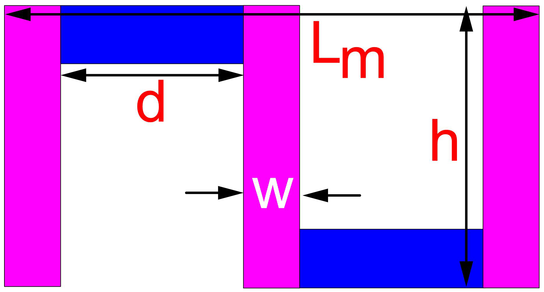
2. Meander Line Antenna Formula
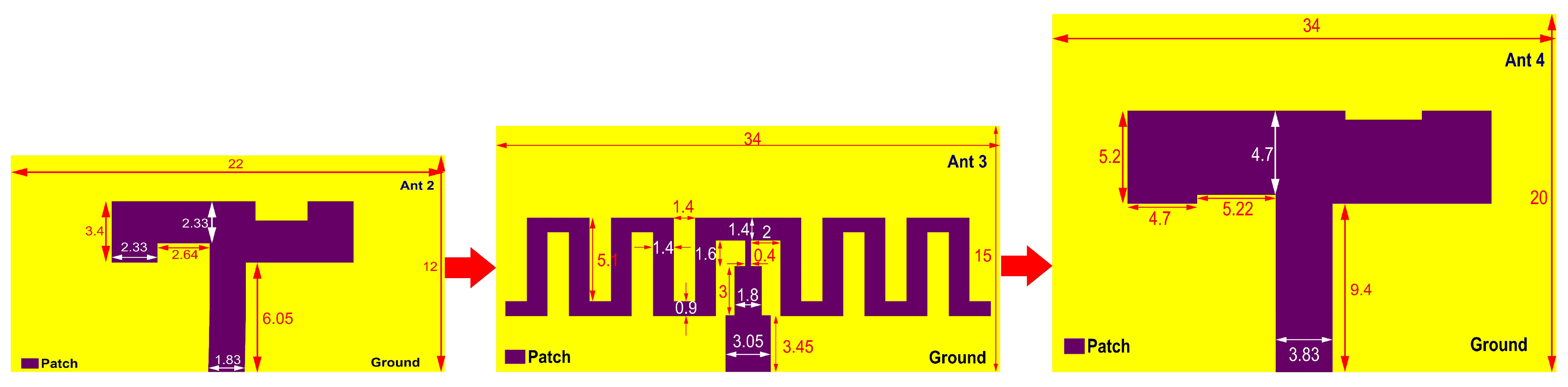
To design a high-quality 5G antenna, it is important to consider the substrate material’s impact on the gain, efficiency, and reflection coefficient. The substrate material’s permittivity, thickness, and loss tangent all play critical roles in ensuring reliable radio frequency quality, cost-effective hardware, and maximum efficiency. Choosing the right substrate material is crucial to ensure optimal performance. Common dielectric substrates include FR-4: a widely used epoxy-based substrate known for its cost-effectiveness and ease of fabrication. However, it has limitations in terms of high dielectric loss and limited frequency capability. Rogers Corporation produces high-performance laminates, such as the RO4000 series, which offer lower dielectric loss and better stability across a broad frequency range. Ceramic substrates, like alumina (Al2O3) and aluminum nitride (AlN), exhibit excellent thermal conductivity and are suitable for high-power applications. However, they can be brittle and challenging to process. Polytetrafluoroethylene (PTFE) substrates, such as Rogers RT/Duroid, are known for their low dielectric constant and low loss tangent, making them suitable for high-frequency designs, but they can be more expensive. The selection of a dielectric substrate depends on the specific application requirements, including the frequency range, power handling capability, thermal properties, and cost considerations. Designers must carefully evaluate these factors to choose the most appropriate substrate for achieving optimal performance in electronic circuits. FR4 and RT/Duroid substrates are commonly used in 5G/6G antennas due to their desirable electrical properties. Among these, FR4 is a cost-effective and popular substrate material for printed circuit boards (PCBs) due to its mechanical durability and low cost [32,33]. However, it is important to note that different 5G antenna designs may require different substrate materials to achieve optimal performance. For instance, for higher frequencies, a low loss higher dielectric constant substrate yields better radiation performance and bandwidth.
It is crucial to calculate the meander line element dimensions using mathematical equations that take into account the operating frequency and other design criteria. The dielectric constant ( ϵ r ) and substrate height ( h s ) for planar patch antennas made of FR4 are typically 4.4 and 1.6 mm, respectively. However, determining the appropriate length ( L p ) and width ( W p ) of a meander line antenna for 5G FR1 2.4 GHz and 5G FR2 28 GHz frequencies can be challenging. Fortunately, there are standard formulas available that can assist with calculating these values; these are depicted in Figure 2 and Equations (1)–(16). By verifying these standard equations, engineers can have confidence in using them for their designs [34,35,36]. Once the formulas have been applied, the estimated values for meander line structures Ant1 through Ant4 can be determined and presented in a table, such as Table 1. Impedance matching: To match the impedance of the meander line antenna to the feedline, the following expression can be used to calculate the width of the feedline:
W f e e d = Z 0 ( h ϵ r c )
where W f e e d is the width of the feedline, and Z 0 is the characteristic impedance of the feedline. The characteristic impedance of an antenna feedline is crucial for minimizing signal reflections and maximizing power transfer efficiency. A proper match between the feedline and antenna impedance reduces the Voltage Standing Wave Ratio (VSWR), resulting in lower signal loss and improved transmission performance. Consistent impedance throughout the feedline ensures resonance at the antenna’s operating frequency: optimizing its efficiency and preventing potential damage to associated equipment due to impedance mismatches. Substrate thickness, h, is the thickness of the substrate material; ϵ r is the relative dielectric constant of the substrate material; and c is the speed of light. The substrate thickness in a patch antenna is crucial for determining the antenna’s resonant frequency, bandwidth, and radiation pattern. By adjusting the substrate thickness, we can fine-tune the antenna’s performance to meet specific frequency requirements. Optimal substrate thickness is also essential for suppressing surface waves, improving mechanical stability, and ensuring efficient energy transfer, and it influences the overall effectiveness of the antenna design.
λ g = c f × ε r
Width of the patch:
W p = c 2 × f 2 ε r + 1
Fringing field length:
Δ L = 0.5 × W p
Total length of meander:
L m = 6.5 h s × w
where w = width of meander lines.
Length of the substrate:
L s = L m + h
Width of the substrate:
W s = 2.5 × L m
Listed are the 5G FR1 and FR2 key mathematical expressions used in the design of meander line antennas [37,38,39].
Figure 2. Meander line formula structure [38].
Vehicles 06 00010 g002
Height of meander:
h = 0.42 λ g
Width of meander:
w = 0.05 λ g
Distance of meander:
d = 0.16 λ g
Listed are the 5G FR2 meander line key mathematical expressions that can be modified for broader bandwidth [40,41].
Height of meander:
h = 0.92 λ g
Distance of meander:
d = 0.25 λ g
Width of meander:
w = 0.16 λ g
Listed are the 5G FR2 meander line key mathematical expressions modified for super wideband [40,42,43].
Height of meander:
h = 0.142 λ g + Δ L
Distance of meander:
d = 0.25 λ g + Δ L
Width of meander:
w = 0.16 λ g + Δ L

3. Antenna Design

A microstrip patch antenna’s basic structure and dimensions are proposed in Figure 1. The antenna comprises a meander line patch, dielectric substrate, and continuous ground plane. The dimensions of the substrate are 34 mm × 20 mm × 1.6 mm. The top substrate has a meander line constructed according to the vital mathematical expressions in Section 2: 5G FR2 from Equations (8)–(10). The dielectric material of the substrate has a relative permittivity of ϵ = 4.4 and a thickness of 1.6 mm and is made of FR4 epoxy. A 50 Ω microstrip line feeds this antenna. The meander slot has three vertical widths of 4.7 mm with a height of 5.2 mm and two horizontal widths of 5.22 mm with a height of 4.7 mm. It is placed symmetrically on either side of the microstrip line. The continuous ground plane is set below the radiating patch to improve the antenna’s bandwidth.

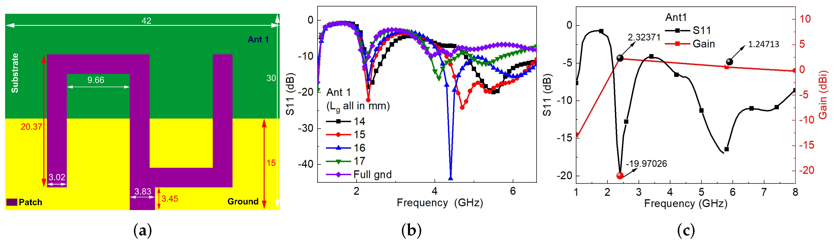
3.1. Design of 5G FR1 Meander Line Antenna

The 5G frequency range 1 (FR1) antennas operate in the frequency range from 410 MHz to 7.125 GHz. They are commonly used for 4G LTE, 5G sub-6 GHz, and other wireless communication standards commonly used for cellular networks and offer good coverage but limited data transfer speeds [2].
Figure 3 displays the construction of Antenna 1 (Ant 1): a meander line antenna that operates at 2.4 GHz and uses the 5G FR1 mathematical expressions from Equations (8)–(11). Ant 1 through Ant 4 were analyzed using the High-Frequency Structure Simulator (HFSS) EM suite version 2020R1. The geometry and structure of Ant 1 are depicted in Figure 3a, and the dimensions are 42 mm × 30 mm × 1.6 mm. Initially, a meander line monopole antenna with a continuous ground was designed, but the results were inadequate as it had dual broadband frequency at 2.2 GHz and 8.5 GHz center frequencies and resonated from 2.14 GHz to 2.30 GHz and 7.76 GHz to 8.57 GHz. The vertical length ( L g ) of the Ant 1 bottom was analyzed for optimization purposes to achieve the required bandwidth at a central frequency of 2.4 GHz. The results indicated that Ant1 with a partial ground structure had a broad dual frequency compared to Ant1 with a full ground, as shown in Figure 3a. Ant1 covers the 2.24 GHz to 2.74 GHz and 4.89 GHz to 7.62 GHz frequency ranges with a −19.97 dB and −16.87 dB reflection coefficient at 2.4 GHz and 5.8 GHz, respectively. Figure 3b highlights the −19.97 dB reflection coefficient and peak gain of Ant1, which is 2.32 dBi for the 2.4 GHz operating frequency. The antenna gain at 5.8 GHz exhibits a modest 1.25 dBi—though it is important to note that this design serves as our baseline design and is primarily utilized for validating our mathematical analyses. Our primary focus lies in the creation of an antenna that operates for 5G-enabled vehicles functioning within the 28 GHz band. Our efforts in this regard have resulted in good antenna gain that surpasses 7 dBi in the 28 GHz band, which meets the essential requirements for 5G vehicular applications.

3.2. Design of 5G FR2 Meander Line Antenna

FR1 antennas are typically larger and have lower gain. Lower-frequency-band antennas, characterized by longer wavelengths, present inherent limitations that impact their design and performance. One primary constraint is the challenge of accommodating larger physical sizes due to the proportional relationship between antenna size and wavelength. This limitation is particularly significant in portable devices and those with space constraints. Lower-frequency antennas typically exhibit lower directivity and gain, which limits their effective range and coverage area. The constrained bandwidth available in lower frequency bands further limits data transfer rates, which affects the overall throughput of communication systems. These antennas are more susceptible to noise and interference from both natural and man-made sources, which potentially compromises signal quality. The ability of lower frequency signals to penetrate obstacles is also compromised, making them less suitable for applications in urban environments. Regulatory restrictions on certain lower frequency bands further contribute to the challenges in designing and deploying communication systems. While lower frequency bands offer extended propagation ranges, the associated limitations necessitate careful consideration in antenna design and deployment, especially in the context of modern communication requirements. FR1 antennas are optimized for coverage and capacity in the lower frequency range, while 5G frequency range 2 (FR2) antennas are optimized for high data rates and focused coverage in the higher frequency range. FR2 antennas operate in the frequency range from 24.25 GHz to 52.6 GHz. They are used for millimeter-wave (mmWave) 5G deployments, which offer very high data transfer speeds but have limited coverage due to their shorter range [6,15]. A monopole meander line via continuous ground with modifications of meander line width, length, and turns can obtain wideband and also improve the antenna directivity at 5G FR2 bands.
Figure 4 discusses the design flow of a proposed antenna with a continuous ground plane. Antennas Ant2 to Ant4 have been developed based on the key mathematical expressions for 5G FR2 from Equations (11)–(16). The design process initiates with Ant2 and concludes with Ant4. Figure 5 illustrates the S11 parameter and the design flow gain for Ant2 to Ant4. The 5G FR2 design flow for a super-wideband meander line antenna spanning from 24 GHz to 30 GHz in terms of S-parameters is presented in Figure 5a, with the gain specifically depicted at 28 GHz in Figure 5b. The initial design of Ant2 incorporates a 50 Ω microstrip line feed measuring 22 mm × 12 mm × 1.6 mm. It primarily focuses on meander width variations with reduced substrate geometry. Ant2 resonates from 26.78 GHz to 28.62 GHz, exhibits a −13.25 dB reflection coefficient and a peak gain of 7.3 dBi, and showcases a single narrowband frequency at the center frequency of 28 GHz. Ant3 extends the structural design of Ant2 by emphasizing meander length and substrate geometry. With dimensions of 34 mm × 15 mm × 1.6 mm, Ant3 introduces a wideband frequency range from 24.47 GHz to 30 GHz. At 28 GHz, it displays a −23.45 dB reflection coefficient and a peak gain of 6.10 dBi, outperforming Ant2. The meander line configuration of Ant3 involves multiple segments with varying widths and increasing lengths that generate numerous resonances that enhance the antenna’s bandwidth. To broaden the frequency, Ant3 is fed through a quarter-wave transformer (QWT) feedline. Finally, Ant4 is a meander line antenna featuring width and length variations. It is powered by a 50 Ω microstrip line feed and is constructed on a full ground plane to encompass both the lower and upper bands of the 28 GHz range. The width of the meander line affects the antenna’s capacitance and inductance, while the length only affects the line’s delay. This technique helps to increase the antenna’s bandwidth to super-wideband by introducing multiple resonances and reducing the mismatch between the antenna and its feedline. The Ant4 structure is super-wideband and covers 5G micrometer, radar, satellite, and millimeter (mm-wave) applications and high peak gain compared to Ant 2 and Ant 3, as displayed in Figure 5b.

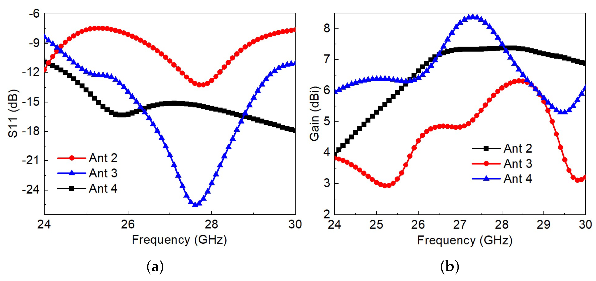
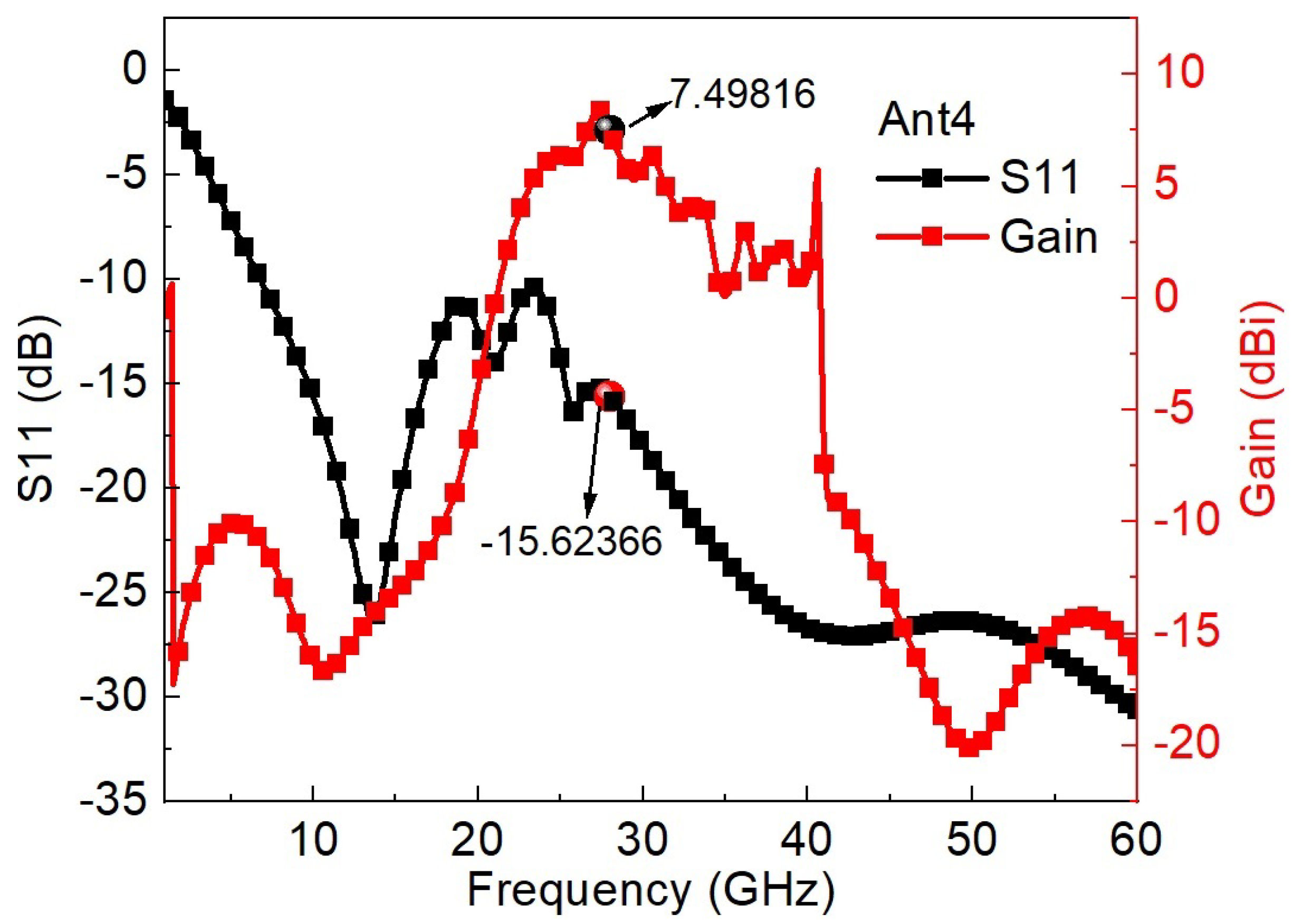
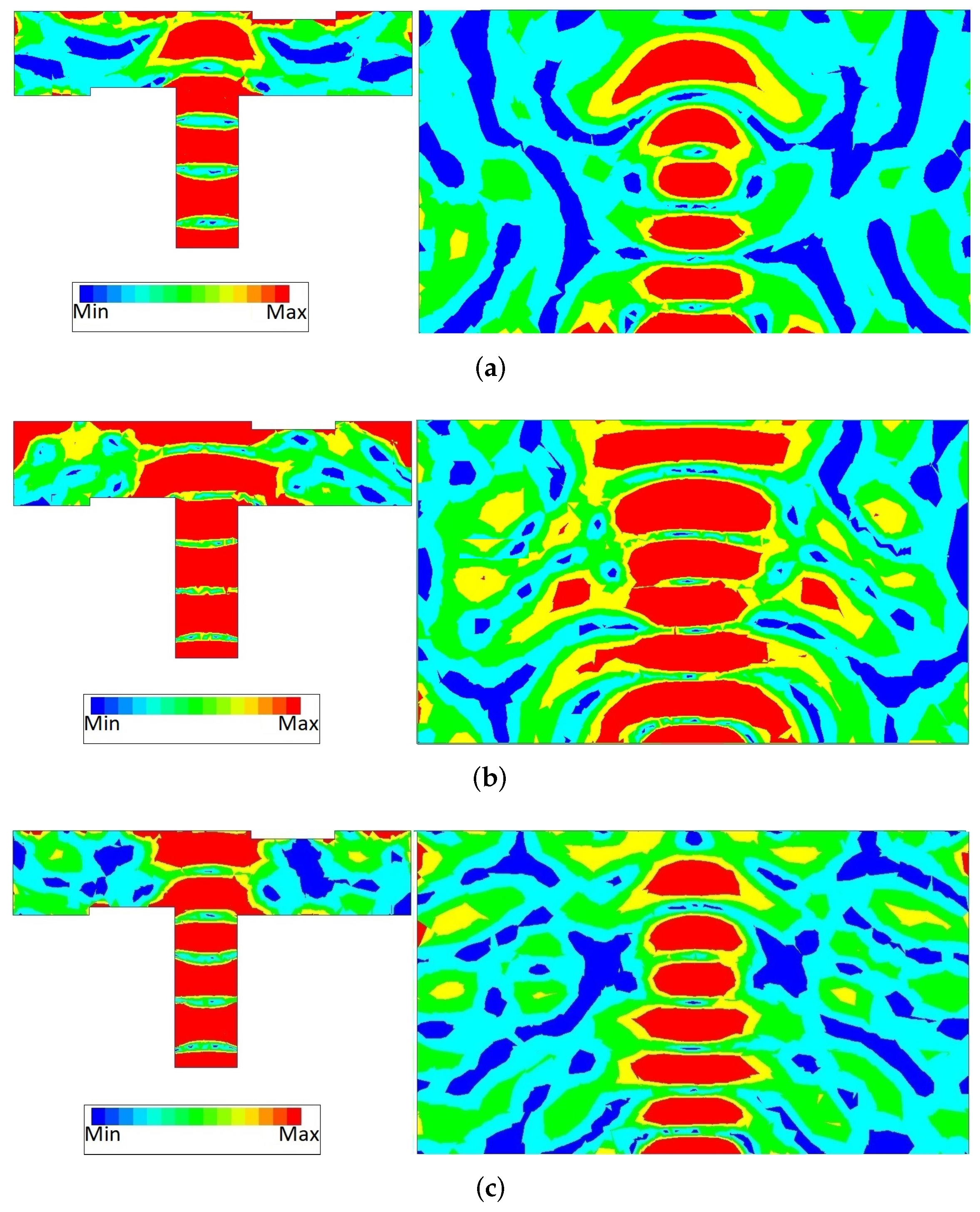
4. Results and Discussion
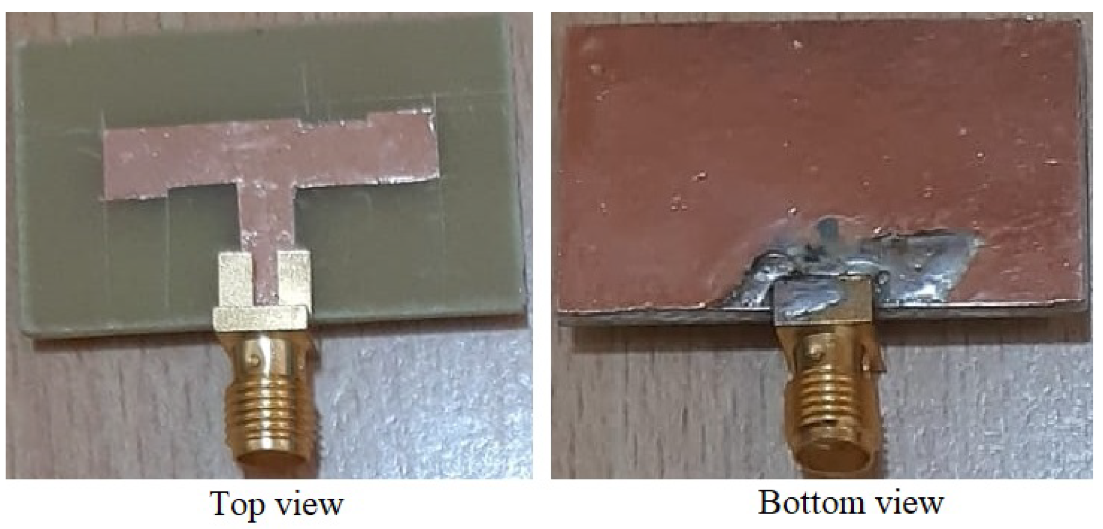
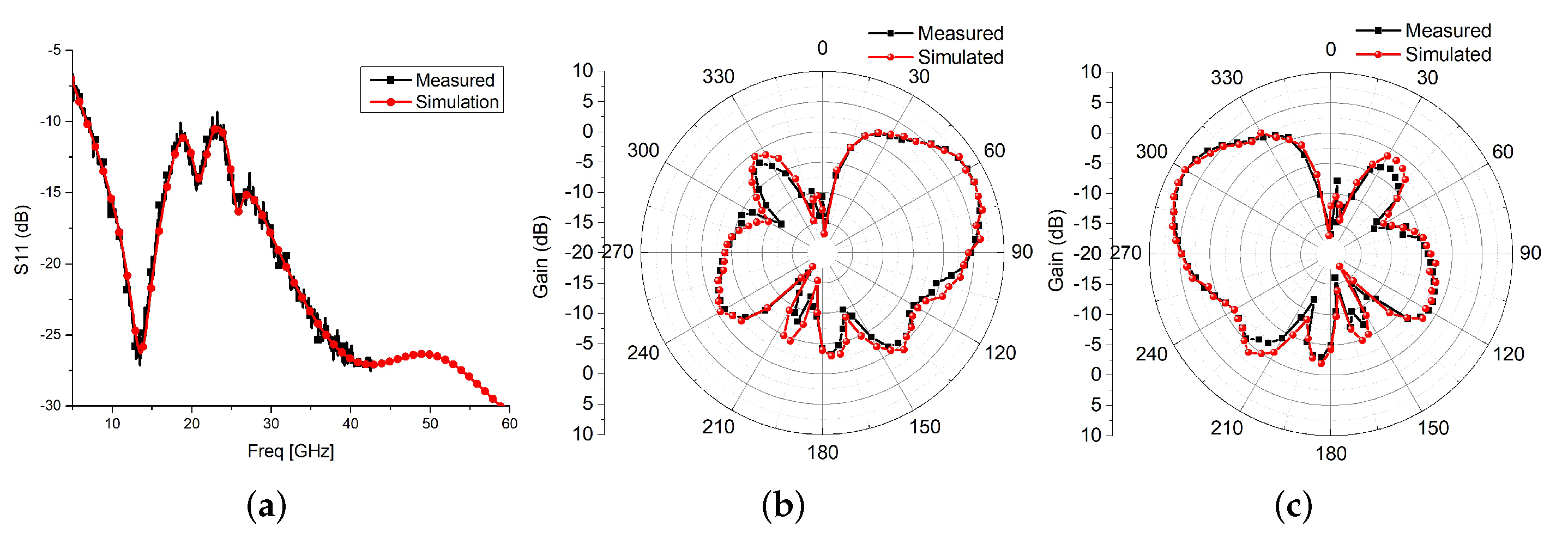
The finalized design of Ant4, which has a super wideband of 53.4 GHz from 6.79 GHz to 60 GHz, and its simulated S-parameter and gain plots are displayed in Figure 6. Additionally, Ant4’s patch and ground surface current at 24 GHz, 26 GHz, and 28 GHz are shown in Figure 7, which shows that the 24 GHz surface current distribution exhibits more radiation at the center of the patch in Figure 7a, while the 26 GHz surface current distribution shows more radiation at the center and top corner edges of the patch in Figure 7b. Similarly, the 28 GHz surface current distribution displays more radiation at the patch’s center and top center edge in Figure 7c. Interestingly, all three surface current distributions exhibit more radiation at the center of the continuous ground plane, as shown in Figure 7. Implementing the Ant4 design of the continuous ground, adding 0.5 W p meander line width, and adding 6.5 h s to the substrate length and width report remarkable results, and the bandwidth is improved compared to the Ant2 and Ant3 designs. This component can benefit wideband applications in the 5G and 28 GHz mm-wave bands. The proposed meander line antenna’s performance is evaluated by comparing it with several antennas inspired by meander line designs, as detailed in Table 2. The results demonstrate that the proposed antenna exhibits gain, bandwidth, and compactness on par with those reported in the existing literature. The proposed antenna exhibits a comparable response and is suitable for its intended application.

Measured Results

The prototype of the 5G FR-II band antenna is developed and depicted in Figure 8. The antenna is developed on an FR4 substrate and 0.07 mm thin adhesive copper tape. As per availability, a 40 GHz connector is used to connect the 43.5 GHz vector network analyzer (VNA) for the measurement. Also the full range of the VNA is used for the scattering parameter measurement, leading to a higher noise level in the measured results. Measuring the scattering characteristics of patch antennas poses challenges related to accurate near-field assessments, precise frequency coverage, and polarization considerations. Achieving a true far-field condition for measurements can be difficult in limited-space environments, which impacts the reliability of the results. Precise calibration of the measurement system is essential to mitigate errors, and the influence of surrounding materials on antenna performance must be carefully addressed during testing. However, simulated results show that the antenna resonates beyond 60 GHz.
The measured scattering parameter and radiation patterns at 28 GHz are shown in Figure 9. The agreement between the measured and simulated scattering parameters are satisfactory. This validates the proposed design approach and the theoretical calculations of the meander-line-radiator-based wideband antenna. The antenna’s complex radiation pattern may require sophisticated measurement setups to capture its directional properties comprehensively. Ensuring precise antenna positioning and calibration becomes crucial to mitigate errors and achieve reliable radiation pattern data. Addressing these challenges demands a careful balance of advanced measurement techniques and meticulous experimental procedures. However, the good agreement seen between simulated electric and magnetic field radiation patterns also confirms successful radiation from the proposed structure. The dimensions calculated for the desired operating bands are identical between simulation and measurement and have satisfactory radiation characteristics. The radiation efficiency of the antenna as measured at 28 GHz was found to be 87.9%.

5. Conclusions

A comprehensive design approach for a meander line radiator tailored for super-ultra-wideband (SUWB) applications is presented. The demonstrated approach successfully designs a highly wideband radiator suitable for fifth-generation (5G) mobile frequency applications that covers both the lower (sub-6 GHz) and higher (28 GHz) frequency bands. The theoretical calculations employed for dimension determination and the simulation results yield satisfactory measured performance. The proposed design incorporates an aerial patch excited by a microstrip feedline positioned atop the substrate and complemented by a continuous ground plane. By utilizing a theoretical formula, the meander line structure efficiently covers both frequency range 1 (FR1) and frequency range 2 (FR2) of the upper 5G frequency spectrum. Operating at 28 GHz, the antenna achieves a peak gain of 7.5 dBi. The simulation demonstrates an impressive bandwidth ratio (BWR) of 9.09:1 for a −10 dB reflection coefficient and spanning a wide frequency range of 53.4 GHz (ranging from 6.6 GHz to 60 GHz). With its compact linear meander line planar structure occupying a small area of 34 mm × 20 mm × 1.6 mm, the proposed antenna fulfills the bandwidth requirements for diverse applications such as radar, satellite communication, 5G millimeter-wave transmission, and the sub-bands of the sixth generation.

Author Contributions

Methodology, S.P.; software, N.R.P.; validation, N.R.P. and S.P.; investigation, N.R.P.; resources, J.K.; data curation, J.K.; writing—original draft preparation, N.R.P.; writing—review and editing, J.K.; visualization, S.P.; supervision, J.K. All authors have read and agreed to the published version of the manuscript.

Funding

This research received no external funding.

Data Availability Statement

Data are contained within the article.

Conflicts of Interest

The authors declare no conflict of interest.

References

  1. Chung, M.A.; Tseng, K.C.; Meiy, I.P. Antennas in the Internet of Vehicles: Application for X Band and Ku Band in Low-Earth-Orbiting Satellites. Vehicles 2023, 5, 55–74. [Google Scholar] [CrossRef]
  2. Jain, P.; Gupta, A.; Kumar, N.; Guizani, M. Dynamic and Efficient Spectrum Utilization for 6G with THz, mmWave, and RF band. IEEE Trans. Veh. Technol. 2023, 72, 3264–3273. [Google Scholar] [CrossRef]
  3. De Fazio, R.; Mattei, V.; Al-Naami, B.; De Vittorio, M.; Visconti, P. Methodologies and Wearable Devices to Monitor Biophysical Parameters Related to Sleep Dysfunctions: An Overview. Micromachines 2022, 13, 1335. [Google Scholar] [CrossRef] [PubMed]
  4. Kim, H.; Kim, E.; Choi, C.; Yeo, W.H. Advances in Soft and Dry Electrodes for Wearable Health Monitoring Devices. Micromachines 2022, 13, 629. [Google Scholar] [CrossRef] [PubMed]
  5. Hashimoto, Y.; Ishihara, T.; Kuwabara, K.; Amano, T.; Togo, H. Wearable Microfluidic Sensor for the Simultaneous and Continuous Monitoring of Local Sweat Rates and Electrolyte Concentrations. Micromachines 2022, 13, 575. [Google Scholar] [CrossRef] [PubMed]
  6. Lorincz, J.; Klarin, Z.; Begusic, D. Advances in Improving Energy Efficiency of Fiber–Wireless Access Networks: A Comprehensive Overview. Sensors 2023, 23, 2239. [Google Scholar] [CrossRef] [PubMed]
  7. Rasheed, I.; Asif, M.; Ihsan, A.; Khan, W.U.; Ahmed, M.; Rabie, K.M. LSTM-based distributed conditional generative adversarial network for data-driven 5G-enabled maritime UAV communications. IEEE Trans. Intell. Transp. Syst. 2022, 24, 2431–2446. [Google Scholar] [CrossRef]
  8. Zhu, Y.; Dong, Y.; Bornemann, J.; Gu, L.; Mamedes, D.F. SIW Triplets Including Meander-Line and CRLH Resonators and Their Applications to Quasi-Elliptic Filters. IEEE Trans. Microw. Theory Tech. 2022, 71, 2193–2206. [Google Scholar] [CrossRef]
  9. Dadgarpour, A.; Antoniades, M.A.; Sebak, A.; Kishk, A.A.; Sorkherizi, M.S.; Denidni, T.A. High-gain 60 GHz linear antenna array loaded with electric and magnetic metamaterial resonators. IEEE Trans. Antennas Propag. 2020, 68, 3673–3684. [Google Scholar] [CrossRef]
  10. Zheng, D.; Lyu, Y.L.; Wu, K. Longitudinally slotted SIW leaky-wave antenna for low cross-polarization millimeter-wave applications. IEEE Trans. Antennas Propag. 2019, 68, 656–664. [Google Scholar] [CrossRef]
  11. Karmakar, A. Fractal antennas and arrays: A review and recent developments. Int. J. Microw. Wirel. Technol. 2021, 13, 173–197. [Google Scholar] [CrossRef]
  12. Lv, X.; Ako, R.T.; Bhaskaran, M.; Sriram, S.; Fumeaux, C.; Withayachumnankul, W. Frequency-selective-surface-based mechanically reconfigurable terahertz bandpass filter. IEEE Trans. Terahertz Sci. Technol. 2022, 12, 257–266. [Google Scholar] [CrossRef]
  13. Liu, Y.; Bian, L.A.; Xu, K.D.; Huang, K.; Wang, Y.; Li, Y.; Xie, S. A Pattern-Reversal Wideband Antenna Integrating Metal Rings, Diodes-Loaded Stubs and Defective Ground. IEEE Open J. Antennas Propag. 2022, 3, 722–731. [Google Scholar] [CrossRef]
  14. Ran, J.; Wu, Y.; Jin, C.; Zhang, P.; Wang, W. Dual-Band Multi-Polarized Aperture-Shared Antenna Array for Ku-/Ka-Band Satellite Communication. IEEE Trans. Antennas Propag. 2023, 71, 3882–3893. [Google Scholar] [CrossRef]
  15. Padhi, J.; Shrikanth Reddy, G.; Kumar, A. Multiple stubs loaded efficient electrically small antenna for DCS/WiMAX/5G NR-n77/n78 applications. J. Electromagn. Waves Appl. 2023, 37, 271–281. [Google Scholar] [CrossRef]
  16. Zhou, Z.; Ge, Y.; Yuan, J.; Xu, Z.; Chen, Z.D. Wideband MIMO Antennas with Enhanced Isolation Using Coupled CPW Transmission Lines. IEEE Trans. Antennas Propag. 2023, 71, 1414–1423. [Google Scholar] [CrossRef]
  17. Lian, J.W.; Ansari, M.; Hu, P.; Guo, Y.J.; Ding, D. Wideband and High-Efficiency Parallel-Plate Luneburg Lens Employing All-Metal Metamaterial for Multibeam Antenna Applications. IEEE Trans. Antennas Propag. 2023, 71, 3193–3203. [Google Scholar] [CrossRef]
  18. Bosman, D.; Huynen, M.; De Zutter, D.; Sun, X.; Pantano, N.; Van Der Plas, G.; Beyne, E.; Ginste, D.V. Analysis and Application of a Surface Admittance Operator for Combined Magnetic and Dielectric Contrast in Emerging Interconnect Topologies. IEEE Trans. Microw. Theory Tech. 2023, 71, 2794–2806. [Google Scholar] [CrossRef]
  19. Kumar, J. Comact MIMO antenna. Microw. Opt. Technol. Lett. 2016, 58, 1294–1298. [Google Scholar] [CrossRef]
  20. BharathiDevi, B.; Kumar, J. Small frequency range discrete bandwidth tunable multiband MIMO antenna for radio/LTE/ISM-2.4 GHz band applications. AEU-Int. J. Electron. Commun. 2022, 144, 154060. [Google Scholar] [CrossRef]
  21. Nikam, P.B.; Kumar, J.; Sivanagaraju, V.; Baidya, A. Dual-band reconfigurable EBG loaded circular patch MIMO antenna using defected ground structure (DGS) and PIN diode integrated branch-lines (BLs). Measurement 2022, 195, 111127. [Google Scholar] [CrossRef]
  22. Rappaport, T.S.; Sun, S.; Mayzus, R.; Zhao, H.; Azar, Y.; Wang, K.; Wong, G.N.; Schulz, J.K.; Samimi, M.; Gutierrez, F. Millimeter Wave Mobile Communications for 5G Cellular: It Will Work! IEEE Access 2013, 1, 335–349. [Google Scholar] [CrossRef]
  23. Alanazi, M.D. A Review of Dielectric Resonator Antenna at Mm-Wave Band. Eng 2023, 4, 843–856. [Google Scholar] [CrossRef]
  24. Ravi, K.C.; Kumar, J. Multi-directional Wideband Unit-element MIMO Antenna for FR-2 Band 5G Array Applications. Iran. J. Sci. Technol. Trans. Electr. Eng. 2022, 46, 311–317. [Google Scholar] [CrossRef]
  25. Chand Ravi, K.; Kumar, J.; Elwi, T.A.; Mahdi Ali, M. Compact MIMO antenna for 5G Applications. In Proceedings of the 2022 IEEE ANDESCON, Barranquilla, Colombia, 16–19 November 2022; pp. 1–6. [Google Scholar] [CrossRef]
  26. Rohde & Schwarz. Millimeter-Wave Beamforming: Antenna Array Design Choices & Characterization. Rohde & Schwarz Application Note. Available online: www.rohde-schwarz.com/in/applications/millimeter-wave-beamforming-antenna-array-design-choices-characterization-white-paper_230854-325249.html (accessed on 1 September 2023).
  27. Palepu, N.R.; Kumar, J. Neutralized meander line patch antipodal vivaldi defected ground millimeter-wave (mm-wave) antenna array. AEU-Int. J. Electron. Commun. 2023, 166, 154663. [Google Scholar] [CrossRef]
  28. Maamria, T.; Challal, M.; Benmahmoud, F.; Fertas, K.; Mesloub, A. A novel compact quad-band planar antenna using meander-line, multi-stubs, and slots for WiMAX, WLAN, LTE/5G sub-6 GHz applications. Int. J. Microw. Wirel. Technol. 2023, 15, 852–859. [Google Scholar] [CrossRef]
  29. Li, H.; Li, B.; Zhu, L. Direct synthesis and design of wideband linear-to-circular polarizers on 3-D frequency selective structures. IEEE Trans. Antennas Propag. 2022, 70, 9385–9395. [Google Scholar] [CrossRef]
  30. Islam, S.; Zada, M.; Yoo, H. Low-Pass Filter Based Integrated 5G Smartphone Antenna for Sub-6-GHz and mm-Wave Bands. IEEE Trans. Antennas Propag. 2021, 69, 5424–5436. [Google Scholar] [CrossRef]
  31. Hussain, R.; Khan, M.U.; Sharawi, M.S. Design and Analysis of aMiniaturizedMeandered Slot-Line-Based Quad-Band Frequency Agile MIMO Antenna. IEEE Trans. Antennas Propag. 2020, 68, 2410–2415. [Google Scholar] [CrossRef]
  32. Watanabe, A.O.; Ali, M.; Sayeed, S.Y.B.; Tummala, R.R.; Pulugurtha, M.R. A review of 5G front-end systems package integration. IEEE Trans. Components, Packag. Manuf. Technol. 2020, 11, 118–133. [Google Scholar] [CrossRef]
  33. Li, C.H.; Chiu, T.Y. Low-Loss Single-Band, Dual-Band, and Broadband mm-Wave and (Sub-) THz Interconnects for THz SoP Heterogeneous System Integration. IEEE Trans. Terahertz Sci. Technol. 2021, 12, 130–143. [Google Scholar] [CrossRef]
  34. Pozar, D.M. Microwave Engineering; John Wiley & Sons: Hoboken, NJ, USA, 2011. [Google Scholar]
  35. Balanis, C.A. Antenna Theory: Analysis and Design; John Wiley & Sons: Hoboken, NJ, USA, 2015. [Google Scholar]
  36. Mathur, D.; Bhatnagar, S.K.; Sahula, V. Quick estimation of rectangular patch antenna dimensions based on equivalent design concept. IEEE Antennas Wirel. Propag. Lett. 2014, 13, 1469–1472. [Google Scholar] [CrossRef]
  37. Raman, S.; Mohanan, P.; Timmons, N.; Morrison, J. Microstrip-fed pattern-and polarization-reconfigurable compact truncated monopole antenna. IEEE Antennas Wirel. Propag. Lett. 2013, 12, 710–713. [Google Scholar] [CrossRef]
  38. Calla, O.P.N.; Singh, A.; Singh, A.K.; Kumar, S.; Kumar, T. Empirical relation for designing the meander line antenna. In Proceedings of the 2008 International Conference on Recent Advances in Microwave Theory and Applications, Jaipur, India, 21–24 November 2008; IEEE: Piscataway, NJ, USA, 2008. [Google Scholar]
  39. Chu, R.-S.; Lee, K.-M. Analytical method of a multilayered meander-line polarizer plate with normal and oblique plane-wave incidence. IEEE Trans. Antennas Propag. 1987, 35, 652–661. [Google Scholar]
  40. Chew, D.K.; Saunders, S.R. Meander line technique for size reduction of quadrifilar helix antenna. IEEE Antennas Wirel. Propag. Lett. 2002, 1, 109–111. [Google Scholar] [CrossRef]
  41. Gatti, R.V.; Rossi, R. A novel meander-line polarizer modeling procedure and broadband equivalent circuit. IEEE Trans. Antennas Propag. 2017, 65, 6179–6184. [Google Scholar] [CrossRef]
  42. Robbins, W.P.; Polla, D.L.; Glumac, D.E. High-displacement piezoelectric actuator utilizing a meander-line geometry I. Experimental characterization. IEEE Trans. Ultrason. Ferroelectr. Freq. Control 1991, 38, 454–460. [Google Scholar] [CrossRef] [PubMed]
  43. Losito, O.; Dimiccoli, V.; Barletta, D. Meander-line inverted F antenna designed using a transmission line model. In Proceedings of the 8th European Conference on Antennas and Propagation (EuCAP 2014), The Hague, The Netherlands, 6–11 April 2014; IEEE: Piscataway, NJ, USA, 2014. [Google Scholar]
  44. Ullah, S.; Ruan, C.; Sadiq, M.S.; Haq, T.U.; He, W. High efficient and ultra wide band monopole antenna for microwave imaging and communication applications. Sensors 2019, 20, 115. [Google Scholar] [CrossRef]
  45. Awl, H.N.; Mahmud, R.H.; Karim, B.A.; Abdulkarim, Y.I.; Karaaslan, M.; Deng, L.; Luo, H. Double Meander Dipole Antenna Array with Enhanced Bandwidth and Gain. Int. J. Antennas Propag. 2021, 2021, 1–8. [Google Scholar] [CrossRef]
  46. Yu, C.; Yang, S.; Chen, Y.; Wang, W.; Zhang, L.; Li, B.; Wang, L. A super-wideband and high isolation MIMO antenna system using a windmill-shaped decoupling structure. IEEE Access 2020, 8, 115767–115777. [Google Scholar] [CrossRef]
  47. Xiao, C.; Hao, S.; Zhang, Y. 915 MHz Miniaturized Loop Conformal Antenna for Capsule Endoscope. IEEE Trans. Antennas Propag. 2022, 70, 10233–10244. [Google Scholar] [CrossRef]
Figure 1. Dimensions of 5G FR2 (all in mm).
Vehicles 06 00010 g001
Figure 3. 5G FR1 meander line antenna design: (a) Ant1 dimensions (mm), (b) ground variations, and (c) S-parameter and gain.
Vehicles 06 00010 g003
Figure 4. Design flow of 5G FR2 super-wideband meander line antenna for Ant2 to Ant4 (dimensions all in mm).
Vehicles 06 00010 g004
Figure 5. Design flow of 5G FR2 super-wideband meander line antenna for Ant2 to Ant4 (a) S-parameter and (b) gain.
Vehicles 06 00010 g005
Figure 6. Gain and S-parameter of Ant4.
Vehicles 06 00010 g006
Figure 7. Ant4 patch and ground surface current distribution: (a) 24 GHz, (b), 26 GHz, and (c) 28 GHz.
Vehicles 06 00010 g007
Figure 8. Prototype of the super-ultra-wideband antenna.
Vehicles 06 00010 g008
Figure 9. Measured results of the proposed antenna: (a) S11, (b) E-plane pattern at 28 GHz, and (c) H-plane pattern at 28 GHz.
Vehicles 06 00010 g009
Table 1. Meander line theoretical formula and experimentally calculated values (in mm).
Type λ g Theoretical
hwdLmLsWs
Ant16.0420.373.029.6628.383042
Ant25.563.372.332.649.951222
Ant35.565.111.391.3912.351534
Ant45.565.195.224.6719.832034
Table 2. Comparison of proposed design.
ParameterRef. [44]Ref. [45]Ref. [46]Ref. [47]This Work
SubstanceRT5880RT5880FR4polymideFR4
Permittivity ( ϵ r )2.22.24.43.54.4
Volume ( mm 3 )38 × 35 × 1.57100 × 80 × 3.17558 × 58 × 130.5 × 4.6 × 0.0534 × 20 × 1.6
FeedingQWT MSCorporate MS4-port MSOffset MSMS
f 0 (GHz)5.5/8.5/12.8
/18
14.5/16.53.5/5.8/13/
18/25/30
0.9157.5/8.5/12.8
/18/28/38
BWR8.33:11.39:113:79:110:19.09:1
Gain (dBi)6.41013.5−21.57.5
Disclaimer/Publisher’s Note: The statements, opinions and data contained in all publications are solely those of the individual author(s) and contributor(s) and not of MDPI and/or the editor(s). MDPI and/or the editor(s) disclaim responsibility for any injury to people or property resulting from any ideas, methods, instructions or products referred to in the content.

