Abstract
Energy storage plays a fundamental role in balancing the power fluctuations induced by the distributed generation of renewable energy sources. In this scenario, electric vehicles can strongly contribute to exchange power with the grid through their on-board batteries. When the vehicle is parked, the battery can be discharged, injecting active power into the grid, provided that its state of charge will be restored before vehicle utilization. This paper presents a comprehensive step-by-step design of a wireless charger for a Vehicle-to-Home application. The design procedure begins from the constraints disposed by the Italian reference technical rules for Low Voltage utilities and by the standard SAE J2954 for Wireless Power Transfer for electric vehicles. The selection of the output power of the battery is followed by the power sizing of each stage of the bidirectional wireless charger.
1. Introduction
The perpetual increase in electrical energy demand by industry and domestic uses is one of the major concerns for climate change on Earth. As per the world energy outlook 2019 report, CO2 emissions in 2018 reached the highest value [1]. With this background, electric energy production and fossil-fuel-free mobility are earning growing interest to reduce the greenhouse effect. Electric Vehicles (EVs) are commonly identified as one of the prominent solutions for the reduction in the gas emissions and the fossil fuel dependence. In particular, EVs are expected to break the market in coming years, despite some issues that still surround them, mostly related to the battery [1,2], The energy required to recharge a large fleet of EVs is another key point that involves grid stability. In addition to these issues, conventional wired charging presents electric shock risk related to wet conditions, making it unsafe for public use during plug-in or plug-out before and after charging.
An alternative solution for EV charging is represented by the Wireless Power Transfer (WPT) technique: through it, battery charging is possible without any physical connection, thus eliminating the problems associated with conventional wired charging [2,3,4]. The WPT technique for EV charging is based on magnetic coupling between two coils: one placed under the road, termed as the primary coil, and the other on board the vehicle, termed as the secondary coil. In addition to the coupling coils, the WPT system relies on: (i) a power supply connected with the primary coil to generate high-frequency voltage according to SAE report J2954 [5], (ii) resonating capacitors along with the coupling coils to reduce the power supply sizing and increase the efficiency, and (iii) power conversion circuitry on the secondary side to convert the high-frequency-induced voltage into DC voltage suitable for the EV battery charging profile.
In the last few years, EVs have gained new interest from the grid-side point of view to mitigate the power fluctuations of renewable energy sources [6,7,8]. Ref. [9], for instance, demonstrates the grid frequency improvements in an isolated system derived from the EV battery utilization to reduce the impact of wind and solar generation. Such a strategy, known as Vehicle to Grid (V2G) [10], stands on the fact that EVs are parked for most of the day and the energy stored in their batteries can be utilized during this time, provided that their initial state of charge (SoC) is restored before vehicle utilization by the user. The V2G strategy was created for the wired charging infrastructure, but it can be easily reproduced adopting the WPT technology [11], as long as all the unidirectional stages of the WPT systems are replaced by bidirectional ones to allow the power flow in both directions [12]. When considering a domestic or residential EV charging station, the V2G is also called Vehicle to Home (V2H) [13,14]. The customer in this case can either take advantage of the energy stored in the battery supplying its own domestic loads, or inject the power into the grid if the loads require low power [15,16,17]. The V2H strategy helps to stabilize or even reduce the variable power demand of domestic loads, decreasing the overall power cost. In addition, the user could receive remuneration for the service offered to the distribution system.
This article intends to present a comprehensive step-by-step design of a bidirectional wireless system for V2H (BWV2H) application. Since the application refers to a domestic user, the arrangement begins from the rules for the connection to the Low Voltage (LV) grid. After detecting the maximum power and current that can be withdrawn by a typical user, the prescriptions expressed by the standard for WPT for electric vehicles are highlighted. On these bases, the input and output specifications for the BWV2H can be designated. Subsequently, the active power involved at each conversion stage is calculated by the corresponding maximum current and voltage. This allows one to determine the rating power of each power converter and of the passive elements arranging the BWV2H.
In detail, this article is organized as follows. Section 2 shortly introduces the V2G and V2H strategies. Section 3 briefly describes the WPT operations and illustrates the Italian reference technical rules for the connection of active and passive users to the LV electrical utilities (CEI 0-21) [18] and the SAE J2954 standard for WPT for electric vehicles [5]. Section 4 reports the characteristics of the battery and determines the requirements for the input and output power. Section 5 sizes all the power converters involved in the BWV2H through the maximum voltage and current that they have to tolerate. Section 6 analyzes the compensation network and designs the coupling coils and the resonant elements. Section 7 is devoted to presenting and discussing the results obtained in the design stage. Section 8 concludes the paper.
In the paper, lower case letters denote time-variable quantities, whilst capital letters denote peak amplitude quantities. Upper case letters with a bar indicate phasors. Subscripts m, M and N designate minimum, maximum and nominal values of the referred quantities, respectively.
2. Vehicle-to-Home Strategy
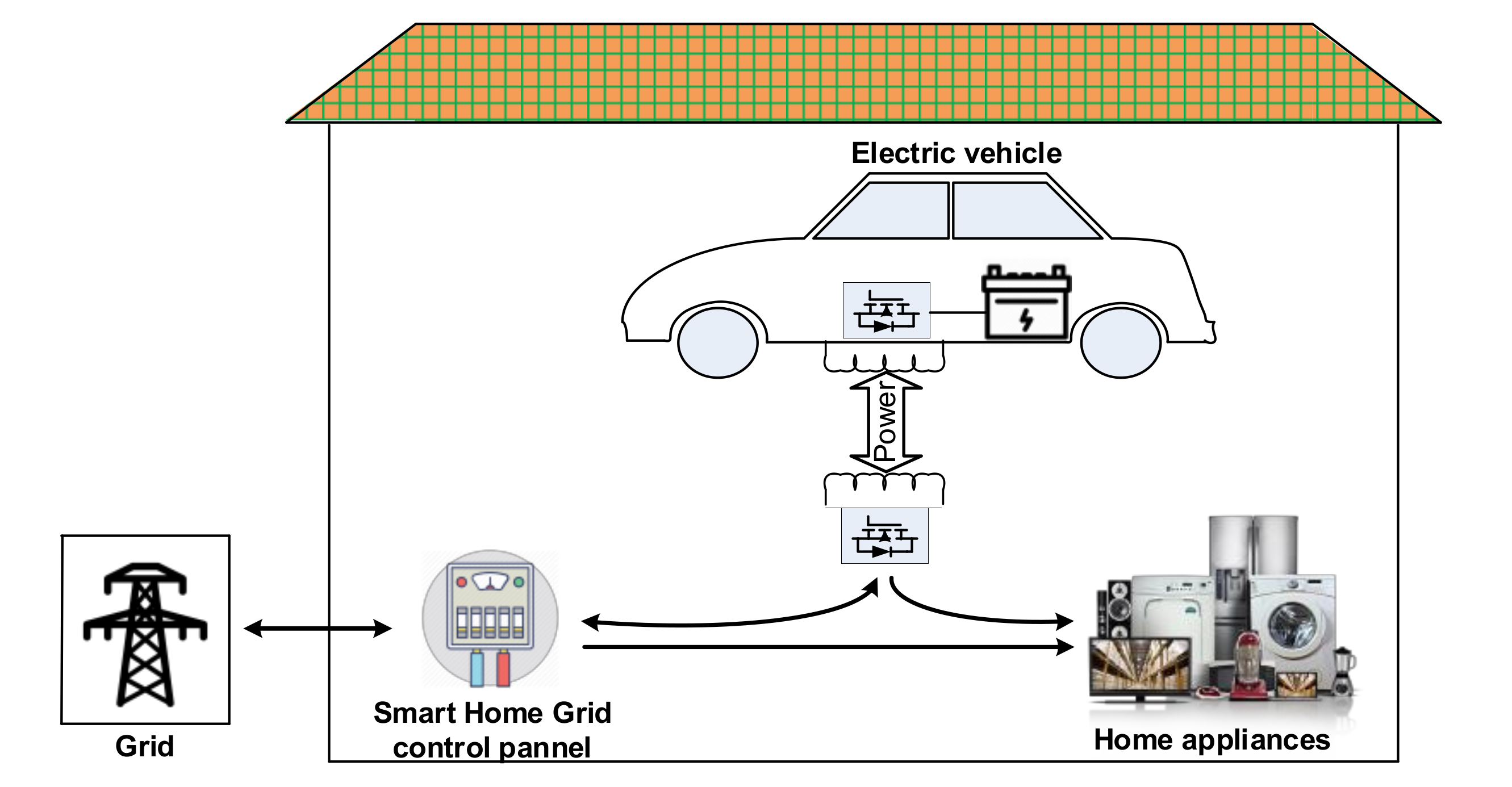
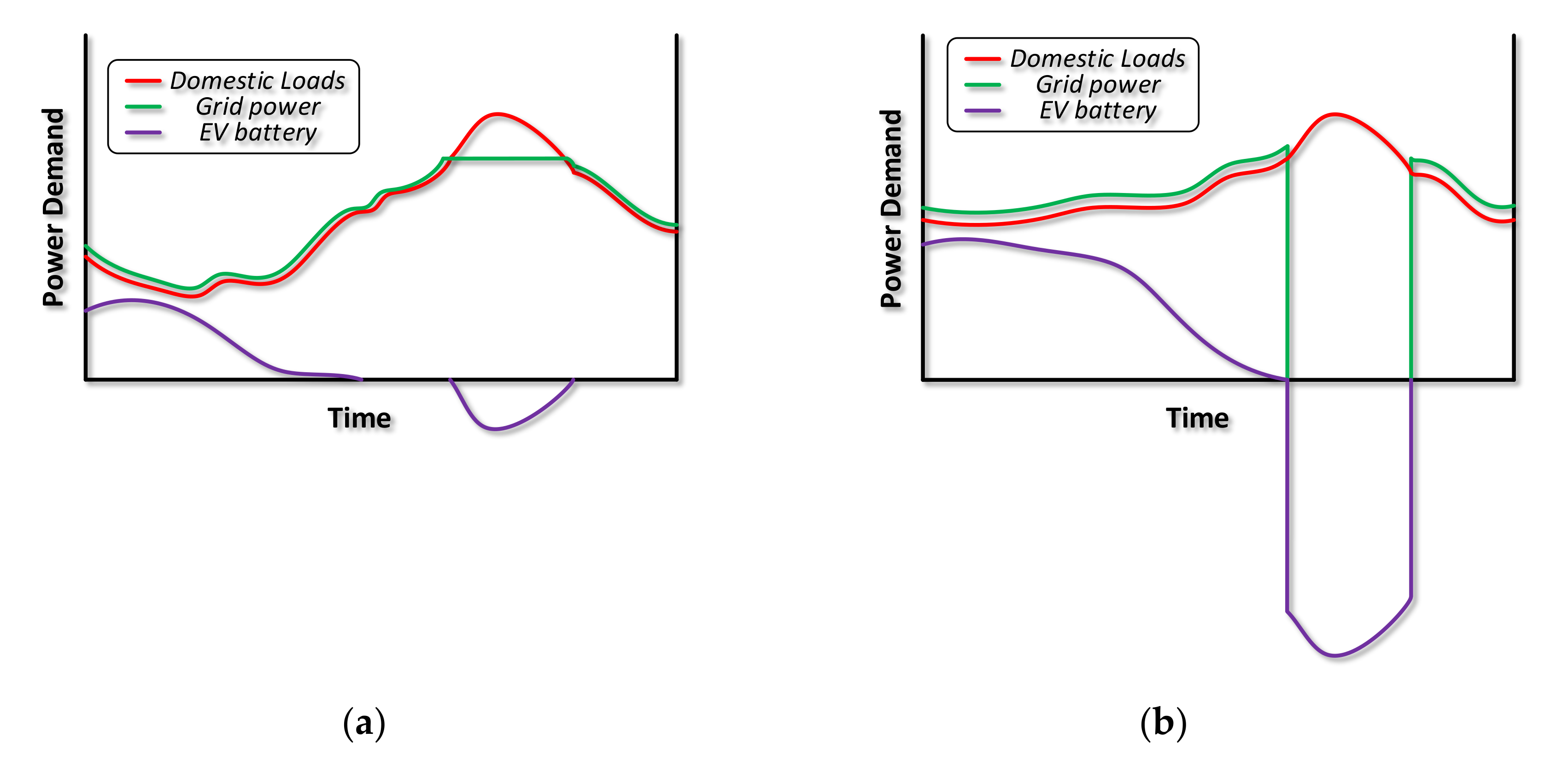
The developments concerning the recharging of EVs batteries allowed their utilization as distributed energy storage systems integrated into the distribution grid [19,20]. This scenario facilitates the flexibility of power management, providing grid services in an efficient and cost-effective way [15], through the so-called V2G concept. The EVs then not only draw the power from the grid, but they can deliver the power back to the grid via a bidirectional charger. In addition, their DC link capacitor inserted in the power conversion chain is inherently able to also provide reactive power to the grid utility [21]. The V2G concept can be easily extended to V2H systems to offer more services. At the household level, the storage capacity presents significant potential such as voltage and load regulations and demand response capability [19,22]. The V2H usually involves a single EV in a single house: its framework is depicted in Figure 1, referring to a WPT charging infrastructure, as the one analyzed in this paper. While charging the battery, the EV absorbs the power from the grid, but while discharging, the power flow has two possible directions: either to the domestic loads or to the main grid, according to the power demand of the home appliances during the discharging process. Figure 2 qualitatively shows two possible application fields of the V2H strategy, where the power absorbed by the domestic loads, from the grid and the EV are represented in red, green and violet line, respectively. Figure 2a represents the peak shaving mode operated by the V2H: in normal conditions, the load power corresponds to the power withdrawn from the grid, but when requesting an amount of power above a certain threshold, the difference is given by the EV battery. This is denoted by the violet line becoming negative. Figure 2b shows an unexpected power outage of the distribution grid: in this case, the presence of the EV battery in the V2H mode allows the domestic loads to be supplied by a backup power despite the outage occurring in the grid.

Figure 1.
BWV2H scheme of principle.
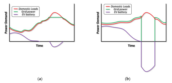
Figure 2.
Application fields of V2H strategy: peak shaving (a) and power backup (b).
3. Operating Requirements of the BWV2H Wireless Charger
WPT chargers stand on the inductive coupling principle between two coils. The alternating magnetic field produced by the alternating current flowing through the coil placed under the road, hereafter called the primary coil, induces a voltage across the coil placed on board the vehicle, hereafter called the secondary coil. The voltage (vs) induced on the secondary coil derives from the well-known Faraday law [23] (1), which can be rewritten as in (2) in the case of sinusoidal quantities, according to Steinmetz transform [24]:
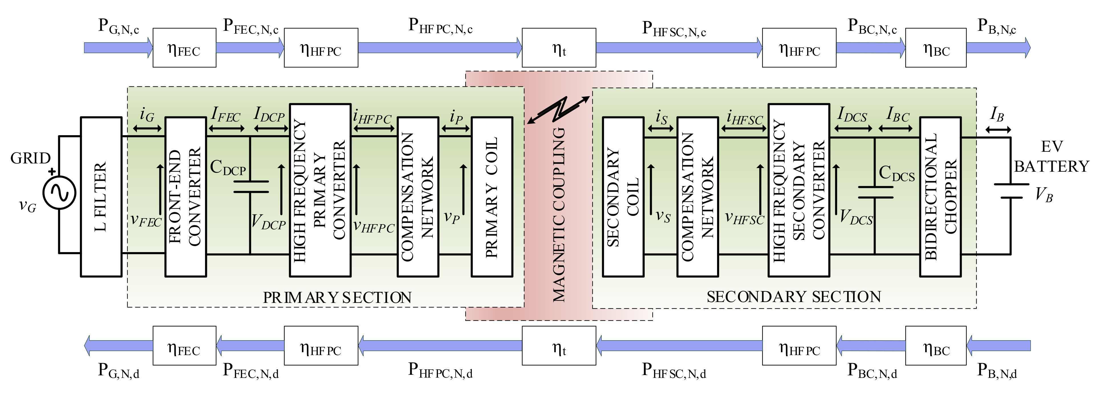
where M is the mutual inductance between the coils, iP is the current flowing through the primary coil, vs and IP are the peak values of vS and iP, and ωHF is the supply angular frequency. Equation (2) is inferred considering the current iP to be purely sinusoidal. Being the induced voltage across the secondary coil dependent from the supply frequency of the primary coil, the highest is the supply frequency fHF, the highest is the efficiency of the power transmission between the two coils and the smaller are the requested size for the two coils. For this reason, the primary coil cannot be directly fed by the grid utility, but several conversion stages are required: specifically, a rectification stage followed by an inversion one, to properly supply the primary coil at a higher frequency. Finally, since the battery calls for Direct Current (DC), a further rectifier is needed on the secondary coil, which can be followed by a chopper to regulate the battery voltage. In a BWV2H application, the power flows alternatively from the grid to the battery and vice versa; then, both the chopper and the rectification stages need to be bidirectional. Figure 3 depicts the architecture of the BWV2H. During charging mode, the grid voltage vG feeds the Front-End Converter (FEC) with the grid current iG through a filter inductor with inductance LG. The FEC output current IFEC is filtered by a capacitor CDCP to maintain the DC primary voltage VDCP as nearly constant. The current IDCP supplies the High-Frequency Primary Converter (HFPC), whose output voltage and current are vHFPC and iHFPC, respectively. The current iHFPC flows in the compensation network and, subsequently, in the primary coil. If a series compensation is adopted, as explained in Section 6, iHFPC corresponds to the current circulating through the primary coil, i.e., iP. The voltage (vs) induced across the secondary coil forces the circulation of the current iS, which corresponds with the current iHFSC at the input of the High-Frequency Secondary Converter (HFSC) in case of series compensation. The input voltage of the HFSC is vHFSC, whilst the output voltage is VDCS, which corresponds to the voltage across the capacitor CDCS. The HFSC output current splits between the current flowing through CDCS and the one at the input of the Bidirectional Chopper (BC), namely IBC. Finally, the BC output voltage and current corresponds to the battery voltage and current, VB and IB, respectively. The FEC, the HFPC and the HFSC are H-bridge converters. The BC can reverse the current flow but not the voltage, which is necessarily lower on the battery-side, i.e., VB < VDCS.
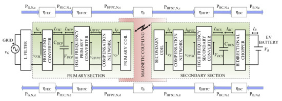
Figure 3.
BWV2H block diagram.
3.1. Reference Technical Rules for the Connection to the LV Electrical Utilities
The BWV2H is meant for domestic user connected to LV utility grid. The majority of these kinds of users have a single-phase connection; therefore, the nominal RMS value of the grid voltage is 230 V [18]. The purpose of this paper is the design and sizing of different active and passive elements and of power converters; therefore, the peak values of all the involved quantities will be hereafter considered. According to [18], the peak value of the nominal grid voltage VG,N that feeds the BWV2H is
with maximum and minimum allowed values, respectively, equal to [18]
and nominal frequency fG,N, as per [18]
The typical contractual power of a domestic customer is 3 kW, where the allowable maximum power PG,N and current IG,N withdrawn by the user, hereafter identified as nominal, are
The main purpose of the BWV2H is recharging the battery of the electric vehicle; nevertheless, in certain conditions, part of the stored energy can be released towards the domestic loads, with the possibility of injecting it in the grid if it is higher than the overall power absorbed by the home appliances. For this reason, the Italian reference technical rules for the connection to the LV electrical utilities (CEI 0-21) [18] categorizes the BWV2H as an active user, also called a prosumer. It is worth noting that the contractual power sets the limits for the maximum absorbable power, but it is not effective for the injected one. In addition, [18] requires that the FEC exchanges reactive power with the grid, according to the diagram of Figure 4. It is shown that when the injected power is between 0 and 0.2PG,N the prosumer can behaves either as an inductive or capacitive load, provided that the power factor cos (φG) is in the range of 0.95 < cos (φG) < 1. When injecting active power in the range 0.2PG,N < PG < 0.5PG,N, cos (φG) must be maintained at 1. Lastly, when the power is higher than 0.5PG,N, the user has to inject reactive power of the capacitive type, behaving as an inductive load, when the grid voltage exceeds a certain lock-in value (f.i., 1.05 VG,N).
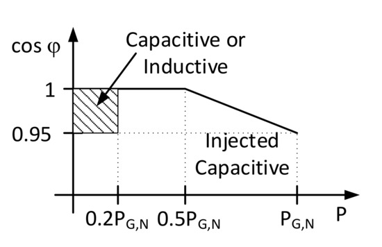
Figure 4.
Power factor cos (φG) as a function of the active power injected into the grid.
3.2. SAE J2954 Standard
SAE J2954 standard establishes an industry-wide specification that defines acceptable criteria for WPT for light-duty plug-in electric vehicles. It addresses unidirectional charging, whilst bidirectional energy transfer may be evaluated in the future. Four power classes are defined (WPT1, WPT2, WPT3 and WPT4) according to the maximum volt-amps drawn from the grid connection, corresponding to 3.3 kVA, 7.7 kVA, 11.1 kVA and 22 kVA, respectively. The vertical distance between the ground surface and the lower surface of the on-board coil identifies the WPT Z-class. The study case presented in this paper refers to a WPT1/Z2 system, with a range of 140–210 mm for the vertical distance.
For WPT1, WPT2 and WPT3, a minimum efficiency of the system is required, measured as the ratio between the active power injected in the battery and the one withdrawn from the grid.
This value has to be maintained in every condition (i.e., minimum or maximum voltage, power, etc.) when the coils are aligned. Instead, in nominal condition, ηtot shall be ≥0.85 while with coil misalignment it shall be ≥0.75. The transmitting coil, which can be either the primary or the secondary in case of bidirectional power transfer, has to be supplied by a voltage with a frequency fHF in the range of 79–90 kHz with a nominal value fHF,N = 85 kHz.
4. Grid-Side and Battery-Side Specification
The specifications concerning the input and output of the BWV2H are determined considering the constraints given by CEI 0-21 and the battery, respectively. Being the power flow bidirectional, the involved quantities are worked out both during the charging and discharging mode, so that the higher values can be subsequently taken as references for the sizing of the power converters.
The electric vehicle’s market is orienting the storage branch towards lithium batteries, due to their high energy density and the long lifecycle. This paper refers to a city car WPT charger, which means the nominal battery voltage VB,N is set at 96 V [25]. Table 1 lists six lithium cells, reporting the nominal, minimum and maximum cell voltage VN, Vm and VM, respectively, the required number of cells to reach the nominal battery voltage VB,N, and the corresponding minimum and maximum battery voltage VB,m and VB,M for each cell type. From these values, in order to carry out a design that is as general as possible, the minimum and maximum chopper voltage VBC,m and VBC,M are selected so that they can accommodate all the cell types listed in Table 1. Specifically, they can be set, respectively, at

Table 1.
Features of lithium cells.
In this paper, LiFePO4 cells, whose characteristics are highlighted in Table 1, are selected as the case study [25]. The battery pack is made of thirty LiFePO4 type cells modules connected in series; its overall nominal capacity is 100 Ah. The nominal battery voltage VB,N is 96 V, while the working voltage of the battery is between 75 V and 109 V so that the output voltage of the BWV2H must be able to vary in this range. The nominal input and output currents are 50 A. The current reference to be injected or extracted from the battery is regulated by the Battery Management System (BMS), which is always included in lithium battery packs, and whose function is to manage the battery charging process and to monitor its discharging process. The BMS also estimates the SoC of the battery, and according to its level manages the battery operation, such as withdrawing power from the vehicle to inject it to the domestic loads, absorbing power from the grid to recharge the battery, or stopping the operations. Accurate SoC estimation is a critical concern for a proper V2G or V2H strategy: to this purpose, several methods were presented, which can be classified into four main categories according to [26]: direct measurements methods, which estimate the SoC through physical measurements; book-keeping estimations that use battery charging and discharging current as input; model-based methods, where the battery parameters and SoC are estimated using adaptive filters and observers; and computer intelligence methods, also called data-driven algorithms [27], which require high computational time and storage size, but can operate without a battery model. Direct measurements methods, such as the ampere-hour, open-circuit voltage and impedance method, ignore the internal model of the battery [28]. Model-based methods consider the battery as a dynamic system, describing its state-space using modelling techniques. A variety of filters and observers, such as the extended Kalman filter [29], unscented Kalman filter [28] and sliding-mode observer [30] are introduced to estimate the state variables. Their performance is related to the model accuracy and the signal collection precision. Finally, the data-driven methods use intelligent algorithms to train the model, such as neural networks [31] and fuzzy logic [32]. The selection of the best method for the SoC estimation related to the BWV2H application is out of the scope of this paper, which aims to size its power stages.
Considering the recommendations of SAE J2954, the total system efficiency ηtot is designated equal to 0.85. The transmission efficiency ηt between the two coils is affected by the alignment, but it is usually above 0.9 [3]. In this work, it is reasonably assumed ηt = 0.92, as found from previous experimental results [4]. The total converter efficiency ηc is therefore equal to
As demonstrated in [4], the efficiency of each power converter is similar to the other ones. As a consequence, the hypothesis that all the converters have the same efficiency ηi (with i = FEC, HFPC, HFSC, BC) is plausible; it derives that it has to be equal to
The nominal power absorbed by the domestic user only for EV charging cannot exceed the one prescribed by the contract and highlighted in (6). As a consequence, the maximum power PB,N,c that can be injected in the battery during the charging mode is equal to
where the subscript N,c states the nominal value during charging mode. The battery absorbs the nominal current IB,N,c in the first stage of the charging process, called the constant-current stage [4]. The nominal current absorbed by the battery with the limitation imposed by the domestic contract is then
It can be observed that it is lower than the nominal battery charging current; this suggests that the charging time will be higher, but at the same time, the battery life will be increased as a result of the diminished thermal stresses. While the battery voltage increases from VB,m up to the maximum value VB,M, the charging current should remain constant. Nevertheless, the power limitation imposed by the domestic contract forces the current to decrease to keep the power constant. Afterwards, the constant-voltage charging stage begins, where the current gradually decreases and so does the power. Subsequently, this charging stage does not affect the sizing of the BWV2H.
During the discharging mode, the vehicle injects the energy stored in its battery towards the domestic loads and, if there is a surplus, in the utility grid. In the extreme case that the home power is null, all the battery power PB,N,d, except the losses, is injected in the grid. Its value corresponds to
where the subscript N,d states the nominal value during discharging mode. According to CEI 0-21, when injecting power into the grid, the power factor must be maintained in the range 0.95 < cos(φG) < 1 by the FEC. In the worst case, i.e., when cos(φG,m) = 0.95 and VG = VG,m, in order to inject the nominal power PG,N,d, the maximum grid-side current IG,M,d is:
The voltages and currents that refer to the grid-side and battery-side of the BWV2H are reported in Table 2. The calculation of the grid-side and battery-side nominal power and the evaluation of the converters efficiencies allows us to determine the active power flow at each stage of the BWV2G, as represented in Table 3.
Table 2.
Specifications for the grid-side and battery-side BWV2H sizing.
Table 3.
Power exchanged in the BWV2G stages.
5. Sizing of the Power Converters
The key elements of a WPT system are the coupling coils and the related compensation networks. Nevertheless, the design of their reactive parameters relies upon the operating parameters of the HFPC and HFSC and, more specifically, on the currents and voltages IHFPC, IHFSC, VHFPC and VHFSC. In turn, these values depend upon the grid-side and battery-side sizing values reported in Table 2 and upon the operating parameters of the FEC and BC, which set the maximum values of the quantities IFEC, VDCP, IBC and VDCS. The sizing of the coils and compensation networks can be realized only after a first approximation design of the power converters, performed from the external ones (i.e., FEC and BC) towards the internal ones (i.e., HFPC and HFSC).
5.1. Front-End Converter
The FEC grid-side is connected to the home network through the LG inductor, whose aim is twofold: decoupling the grid voltage vG from the FEC medium frequency modulated voltage vFEC, and reducing the harmonic content of the grid current iG. The value is set to LG = 3 mH, which allows one to comply with the harmonic current limits established by [33].
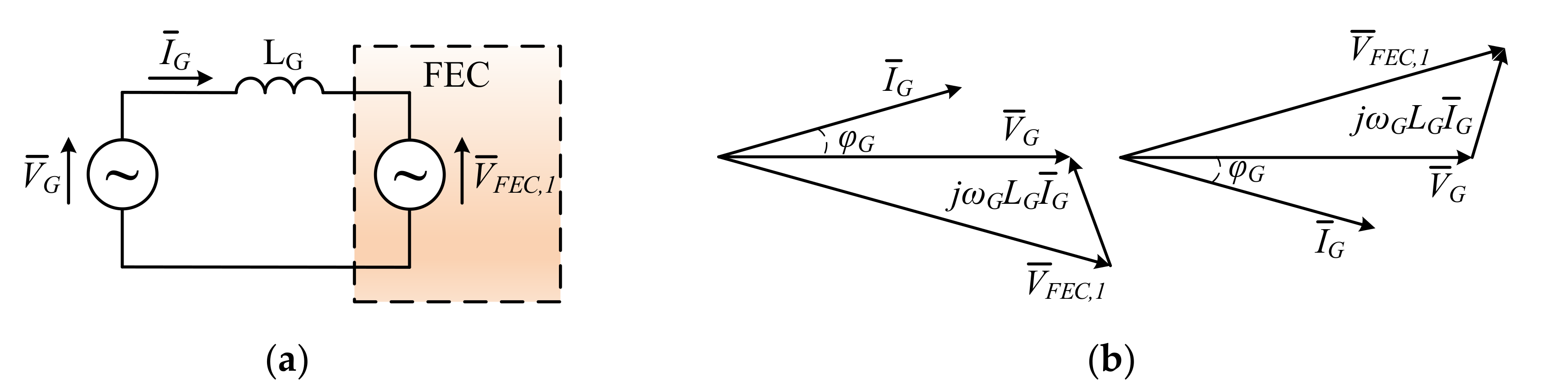
The amplitude of the fundamental component VFEC,1 that must be available at the FEC input can be derived from the equivalent circuit of Figure 5a and its phasor diagram in Figure 5b. The voltage drop on the LG filter inductor must be counterbalanced by an increase in the fundamental component of the voltage VFEC,1. This effect is stronger the more the current IG is out of phase with respect to voltage VG, as can be seen from the following expression of VFEC,1

Figure 5.
(a) Equivalent circuit of the FEC input and (b) related phasor diagram for maximum VFEC,1 during charging and discharging mode, respectively.
Analysis of (15) shows that VFEC,1 is maximum in the condition of maximum grid current and voltage IG,M and VG,M, respectively, maximum grid angular frequency ωG,M = 316.04 rad/s and minimum power factor cos (φG,m) = 0.95. From these values, it is established that VFEC,1,M = 368.88 V. Figure 5b shows that the maximum FEC voltage is reached either during charging mode with the current leading the grid voltage or during discharging mode with the current lagging the grid voltage.
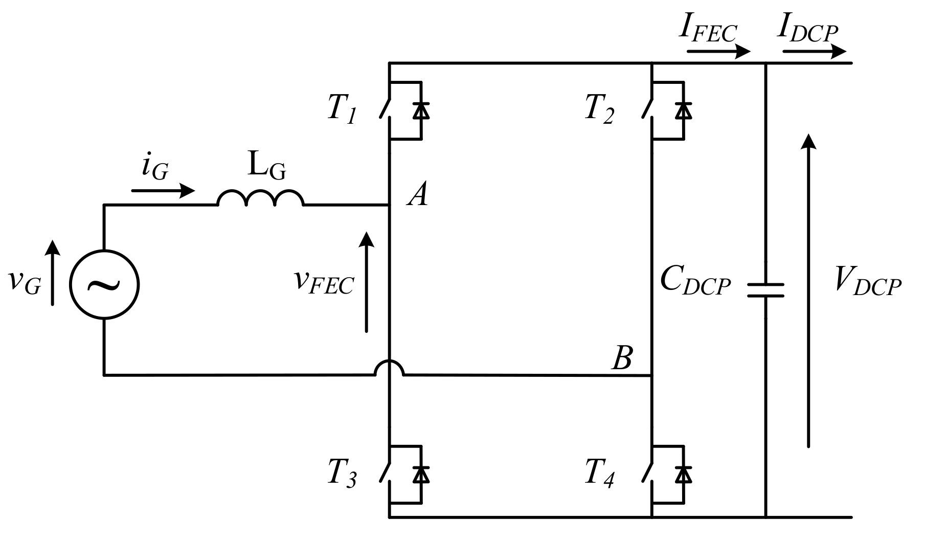
The simplified schematic of FEC interfaced to the grid is shown in Figure 6.
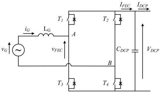
Figure 6.
Grid-side of the BWV2H with convention of the current according to charging mode.
Assuming ideal switches for the FEC, VFEC,1,M is equal to the bus voltage VDCP across the capacitor CDCP. To guarantee the proper operation of the FEC, VDCP must be kept as constant as possible, even though the oscillation induced by the instantaneous power exchanged with the grid cannot be completely eliminated. Assuming a safety margin of 30 V for the proper operation of the BWV2H, the operating VDCP shall be at least equal to 400 V, which is perfectly in accordance with SAE J2954 [5] that establishes
By approximating VDCP with its average value and by neglecting the power exchanged with LG and the power losses in the parasitic resistances, from the instantaneous power balance at the input and at the output of the FEC, it is derived that the low frequency component of iFEC is mainly constituted by a continuous contribution equal to IDCP and a sinusoidal contribution at twice the grid frequency. Ideally, this contribution flows through CDCP and originates a voltage ripple, whose amplitude is given by
From (17), the value of CDCP can be inferred by considering the worst condition (i.e., nominal grid power PG,N and minimum frequency ωG,m = 298.45 rad/s) and assuming a reasonable voltage ripple ΔVDCP = 25 V. Therefore, the capacitor to be installed needs to have a capacitance CDCP at least equal to
Since the fundamental frequency of the alternating component of the current iDCP is equal to 2fHF, i.e., 1700 times higher than the ripple generated by the grid frequency, the value obtained in (17) is sufficient to neglect the high-frequency ripple on VDCP. The voltage VDCP, increased by the allowed voltage variation ΔVDCP/2, corresponds to the voltage to be handled by the switches, which results in 462.5 V. Similarly, the maximum voltage VLG,M that solicitates the filter inductor LG is given by
The maximum current flowing into the switches, in the filter inductor and in the primary DC capacitor, is equal to IG,M.
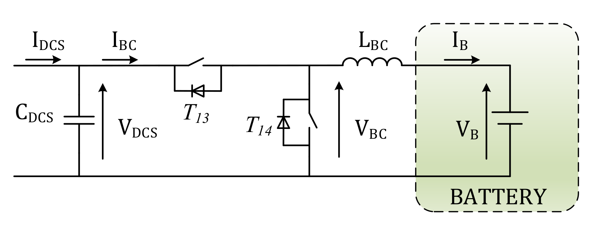
5.2. Bidirectional Chopper
The BC works as a buck converter during charging mode and as a boost converter during discharging mode. Then, it is a two-quadrant DC/DC converter with the possibility of reversing only the current. Its task is to regulate the battery current IB and voltage VB during the charging and discharging process, according to the voltage–current profile supplied by the battery manufacturer. The BC scheme is shown in Figure 7.

Figure 7.
Battery-side of the BWV2H with BC and convention of the current according to charging mode.
As mentioned in (8), VBC,M is set at 120 V. Considering the voltage drop across the BC switches, the voltage VDCS across the capacitor CDCS must be slightly higher than VBC,M; it is then set at
which corresponds to the maximum voltage handled by the HFSC and BC switches. Concerning the current flowing through the BC switches, the maximum current is the discharging current IB,N,d, corresponding to 50 A.
The inductance LBC is interposed between the BC and the battery with a twofold function: decoupling the modulated voltage VBC from the slowly variable battery voltage VB and reducing the current oscillations in order to safeguard the battery life. During the constant-voltage charging stage, the current injected into the battery gradually decreases until it disappears. Therefore, the end of the charging process can be arbitrarily set when the current reduces to 0.05 IB,N,c. The same value is then also imposed as the maximum limit of the peak-to-peak oscillation of the current IB to ensure the continuous conduction of the current throughout the charging process.
Indicating with δBC the duty cycle of the control signal of the upper switch of the BC, in steady-state conditions and neglecting the parasitic resistance of the inductance LBC, the following relation holds:
Assuming continuous conduction operation, the peak-to-peak ripple of the current IB is given by
where TBC is the switching period of the BC. From (21) and (22), it can be derived that ΔIB reaches its maximum value when VB = VBC/2 and that, once exceeding this value, ΔIB decreases as VB increases. In order to carry out a more general design, the worst case among the cells listed in Table 1 is considered. The minimum value of VB is obtained with Li2TiO3 cells, and it is still larger than VBC/2. As a consequence, the maximum value of ΔIB is achieved by charging this type of cells, when the battery voltage reaches the minimum value VB,Li2TiO3,m = 72 V. Assuming that the BC switching frequency is the same of both the HFPC and the HFSC, the current oscillation is maintained within the desired limits for LBC, choosing the minimum value of
where δm is the minimum duty cycle of the BC given by the ratio VB,Li2TiO3,m/VDCS. The maximum current flows in LBC during battery discharging and is equal to IB,N,d, while the maximum voltage applied to its terminals is VBC,M.
The sizing of the DC secondary capacitor CDCS starts by assessing the current flowing through it. The average value of the current IBC is easily derived considering the DC bus voltage VDCS and the power exchanged by the BC during charging and the discharging mode, reported in Table 3.
The average value of IBC is equal to the direct component of current iDCS, which is a rectified sinewave whose amplitude during charging and discharging mode is, respectively:
and whose frequency is twice the switching one, i.e., 170 kHz. The minimum sizing value of the capacitor CDCS can be obtained hypothesizing that it is flown by the alternate component of IDCS and considering the worst operating conditions, i.e., minimum switching frequency ωHF,m = 79 kHz and maximum current IDCS,N,d. By imposing the voltage ripple across CDCS is ΔVDCS = 0.1VDCS, it results in:
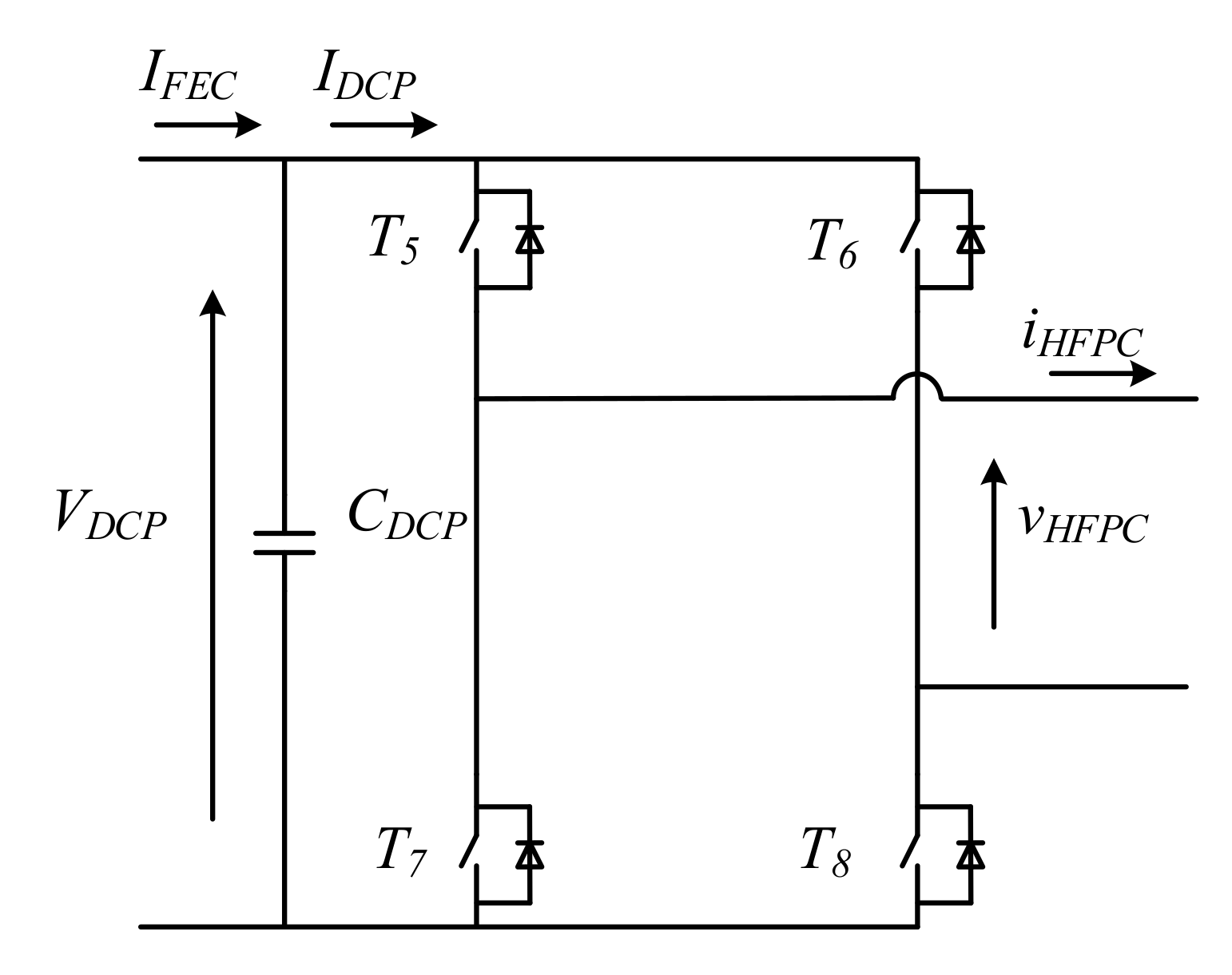
5.3. High-Frequency Primary Converter
The HFPC is a H-bridge converter, as shown in Figure 8. The generation of the high-frequency voltage vHFPC required during charging mode does not allow the utilization of the PWM technique to regulate the amplitude of its fundamental component, since this technique would lead to excessively high switching frequencies. As a result, during the charging mode of the BWV2H, the HFPC is controlled with the phase shift technique, which allows one to obtain a semi-square wave voltage whose fundamental component has a frequency equal to the switching frequency of the HFPC, set at fHF,N, and amplitude given by
where σ is the delay angle between the control signals of T5 and T7 with respect to those of T6 and T8. The maximum value of the fundamental voltage component is reached when the control signals are delayed by π. Neglecting the voltage drop on the switches and the ripple of VDCP, the voltage at the HFPC output is a square wave whose fundamental component amplitude is

Figure 8.
Schematics of the HFPC and convention of the current according to charging mode.
5.4. High-Frequency Secondary Converter
During charging mode, the easiest control solution for the HFSC is to leave all the switches off so that it acts as a diode rectifier. In such an operation mode, the alternated voltage vHFSC depicted in Figure 9 is a square wave voltage in phase with the current iHFSC and with the amplitude of the fundamental component of voltage, given by
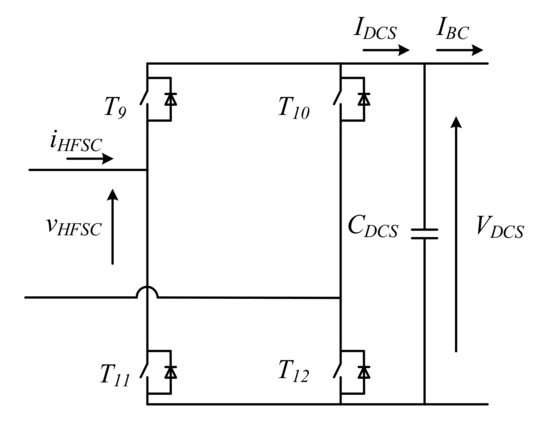
Figure 9.
Schematics of the HFSC and convention of the current according to charging mode.
When the BWV2H operates in battery discharging mode, the HFPC works as a diode rectifier and the HFSC works as an inverter. Maintaining the same control techniques described in Section 5.3, the voltage vHFSC is a semi-square wave voltage with frequency fHF and fundamental component equal to
whose maximum value corresponds to (29). During discharging mode, the voltage vHFPC is a square wave voltage, in phase with the current iHFPC and with an amplitude of the fundamental component equal to (28). The H-bridge schematics of HFSC is shown in Figure 9, where the current direction is drawn according to the charging mode.
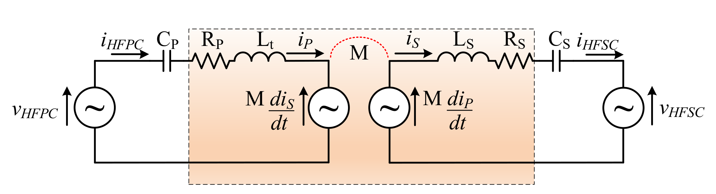
6. Sizing of the Coupling Coils and Compensation Networks
Considering the necessity of a symmetrical behavior for BWV2H in both the power flow directions, the series compensation results to be the preferred one in both the primary and secondary side [4]. This compensation technique forces the current flowing through the coils to be nearly sinusoidal, because the series of the resonant capacitors and the coils self-inductances behave as short circuits at the nominal frequency fHF,N. As a consequence, the voltage induced in the primary and secondary coils are ideally equal to vHFPC and vHFSC, respectively. These features allow us to simplify the schematics of the BWV2H by expressing the voltages vHFPC and vHFSC and the induced voltages across the coils as ideal voltage sources. This leads to the circuital scheme of Figure 10, where RP and RS represent the parasitic resistances of the coils.
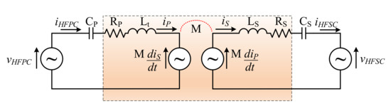
Figure 10.
Schematics of the HFSC with the related quantities.
During battery charging mode, the presence of the parasitic resistances requests the HFPC to generate a voltage fundamental component VHFPC,1 higher than the one induced across the primary coil. In the same way, the voltage fundamental component VHFSC,1 is lower than the one induced across the secondary coil. By defining the primary and secondary coil efficiency as ηt,P and ηt,S, respectively, during the charging mode, the active power flowing from the HFPC output to the secondary coil is given by the first of (31) while the second gives the active power at the input of the HFSC,
From (31), the transmission efficiency can be derived as follows:
Considering two identical coils, the transmission efficiency can be equally divided between primary and secondary coil:
From (33), the voltage fundamental component VHFPC,1 and VHFSC,1 during battery charging mode becomes
where ωHF,N = 2πfHF,N is the nominal angular frequency of the HFPC. For battery discharging mode, dual equations can be written and are therefore omitted in this paper.
Assuming the battery is charged at the power PB,N,c, the power at the input of the HFSC needs to be PHFSC,N,c, as stated in Table 3; therefore, the amplitude of current iHFSC corresponds to
In order for this current to actually flow in the secondary coil, the induced voltage across the primary coil, increased by the voltage drop across RP, needs to be lower than the maximum fundamental component of the voltage vHFPC. From (34), the following inequality can be derived:
Equation (36) states the maximum value for the mutual inductance between the two coupling coils, determined considering the maximum angular frequency ωHF,M.
The value established in (36) needs to be verified also for the discharging mode. The power at AC side of the HFPC is PHFSC,N,d, as expressed in Table 3. The nominal amplitude of current iHFPC,d is
In order for this current to actually flow in the primary coil, the induced voltage across the secondary coil, increased by the voltage drop on RS, needs to be lower than the maximum fundamental component of the voltage vHFSC. Using the dual equation of (34) for the discharging mode, the following inequality is derived:
Equation (38) is stricter than (36); hence, the value of M is fixed at
Once the value of M is set, it is possible to conclude the determination of the current flowing into the coils in both charging and discharging mode, and then size the switches that form the HFPC and HFSC. The worst condition is verified when the frequency is minimum, since higher currents are necessary to obtain the required induced voltages to transfer the predetermined amount of power.
During battery charging mode, the voltage fundamental component of vHFPC in correspondence of minimum operating frequency is
Consequently, to transfer the power PHFPC,N,c, the amplitude of the current supplied by the HFPC has to be
Similarly, in discharging mode the voltage fundamental component of vHFSC in correspondence to the minimum operating frequency is
Consequently, to transfer the power PHFSC,N,d, the amplitude of the current supplied by the HFSC has to be
By comparison between (37) and (41) and between (35) and (43), it can be observed that the primary coil, the primary resonant capacitor and the switches of the HFPC have to be sized according to the current IHFPC,N,c, whilst the secondary coil, the secondary resonant capacitor and the switches of the HFSC have to be sized for the current IHFSC,N,d.
Considering a coupling coefficient k = 0.12, where in-between the minimum and maximum value established by SAE J2954, and assuming the same shape for the two coils, the self-inductance results to be
The resonant capacitors are sized according to the nominal frequency fHF,N
Each coil is subject to a voltage given by the sum of the voltage drop on the self-inductance and the voltage induced by the current flowing through the other coil. With the series resonance topology, the two voltage contributions are π/2 out-of-phase one respect to the other. The nominal voltage on the coils is then equal to
The voltage across the resonant capacitors ideally corresponds to the voltage drop across the self-inductances of the coils, because of the series resonance. The nominal value for the primary capacitor is reached during the charging process, whilst the one across the secondary capacitor is reached during the discharging process:
7. Results and Discussion
This section presents some considerations concerning the sizing of the BWV2H and the simulation results obtained through the MATLAB software. The sizing values of the coupling coil and compensation networks are presented in Table 4, while Table 5 reports the sizing values of the main components of the BWV2H. It can be observed that in the secondary side, a higher current can flow. This leads to higher voltages across both the secondary reactive elements, i.e., LS and CS, as illustrated in Table 4. The current values selected for sizing purposes are the highest between the charging and discharging mode in each stage. The current on the secondary side is strongly related to the sizing of the reactive elements, in particular for the mutual inductance M (and, consequently, for the self-inductances and the resonating capacitor). A higher value of M leads to higher induced voltage and, therefore, a lower current to ensure the requested power transfer.
Table 4.
Sizing values of the BWV2H coupling coils and compensation networks.
Table 5.
Sizing values of the BWV2H power converters.
The cost analysis of a WPT installation was reported in [4] for an EV battery with nominal power of 560 W, i.e., much lower than the one analyzed in this paper. The total cost for the prototype in that case was equal to EUR 5800. Differently from the unidirectional WPT of [4], the FEC, HFSC and BC of the BWV2H are bidirectional converters, contributing to further increase the installation costs; nevertheless, it shall be considered that a future mass-production of such a technology could remarkably decrease its cost.
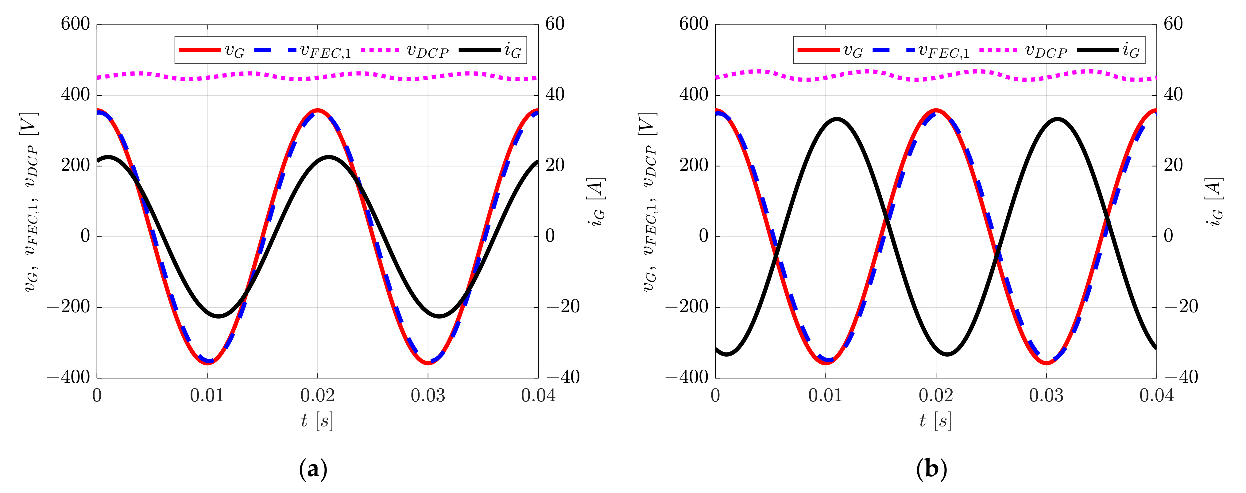
Simulations
This subsection reports the waveforms obtained through the MATLAB software of some quantities involved in the BWV2H operation. At first, the grid-side is analyzed, achieving the results showed in Figure 11. The grid voltage and the FEC voltage are depicted in solid red and dashed blue line, respectively, while the dashed magenta line reports the voltage across the capacitor CDCP and the solid black line reports the grid current, whose peak value corresponds to IG,N = 22.6 A, as highlighted in (6). Figure 11a shows the grid-side of BWV2H during charging mode: it can be observed that the current lags the grid voltage: indeed, the power factor is set at 0.95, i.e., the minimum allowed by CEI 0-21. The voltage vDCP shows the ripple given by the alternating component of current iFEC, whose frequency is twice the grid frequency and whose amplitude is given by (16). Figure 11b shows the same quantities depicted in Figure 11a, but in discharging mode. The phase of the grid current is shifted by 180°and its amplitude is increased to 33.32 A, as described by (14).
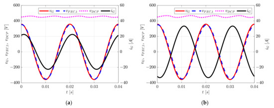
Figure 11.
Grid-side voltage and current waveform in (a) charging and (b) discharging mode, respectively.
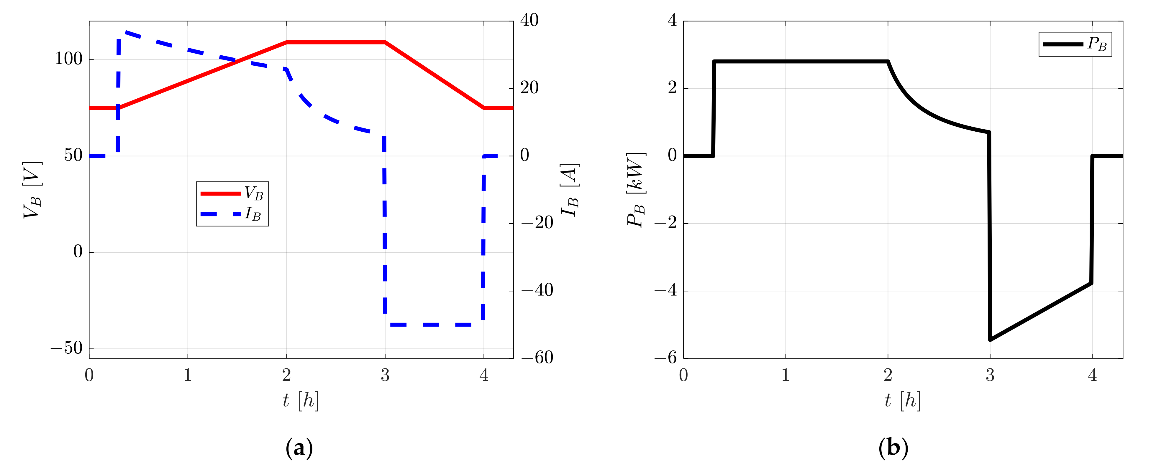
Figure 12 qualitatively presents the quantities related to the battery of the BWV2H, i.e., voltage VB, current IB and power PB, in a solid red, dashed blue and solid black line, respectively. The time scale indicates about 4 h: during the first 3 h, the battery is charging, whilst during the last hour it operates in discharging mode. Different time intervals during charging and discharging mode are divided as follows:

Figure 12.
Battery-related quantities during charging (from 0 to 3 h) and discharging mode (from 3 to 4 h): (a) voltage and current and (b) power.
- 0–0.3 h: the battery voltage is constant at its minimum value VB,m; the current and the power are equal to 0.
- 0.3–2 h: the current initially is at the nominal value IB,N,c given by (12) and the battery voltage increases from VB,m until it reaches the maximum value VB,M; the current consequently decreases in order to comply with the power limitation.
- 2–3 h: the voltage is kept at the maximum value VB,M during the constant-voltage charging stage; simultaneously, the current decreases and so does the power.
- 3–4 h: the battery is in discharging mode. The voltage decreases reaching the minimum value VB,m. The battery delivers the nominal current IB,N,d. The power is maximum only for the first instants when the battery voltage is equal to VB,M, since the current is fixed at IB,N,d; then, the power follows the voltage profile.
- 4–4.3 h: during the last period, the battery voltage is constant at minimum value, whilst the current and the power are equal to 0.
Usually, the first part of battery charging is the constant-current stage, where the voltage increases while the current is kept constant. On the contrary, in this situation when the voltage increases, the current decreases so as to keep the active power constant, as can be observed by inspection of Figure 12a. This is due to the power limit set by the maximum contractual power of the user and expressed by (11). From 3 h to 4 h, the battery is in discharging mode, supplying with its power either the domestic loads or the distribution grid. The discharging mode can be inferred from the reverse of the current and power, which are denoted with a negative sign in the figure. Since no limitation is established by CEI 0-21 for the injected power, the battery is delivering the nominal current IB,N,d throughout the whole discharging process. As a consequence, when the battery voltage decreases, the power follows the voltage profile. The values reported in Figure 12 reflect the ones found in the design part of Section 3. In particular, IB,N,c is equal to 37.4 A and IB,N,d is equal to 50 A, as specified in Table 2. Concerning Figure 12b, in the time interval the power absorbed by the battery is 2.8 kW, corresponding to PB,N,c, whilst the maximum power is delivered only at the beginning of the discharging process (when VB = VB,M), and it is equal to 5.45 kW, as shown in Table 3.
8. Conclusions
This paper presents a comprehensive step-by-step design procedure for a BWV2H, giving a handy instrument for its design, which can be easily utilized for higher power WPT systems. Starting from the Italian reference technical rule for the connection of active loads to the LV utility and from the SAE J2954 standard for WPT chargers, the initial constraints are set, regarding the grid-side quantities and the efficiency and operational frequency of the WPT. Subsequently, the grid-side and battery-side specifications are derived, together with the power limits in each stage of the BWV2H. The maximum allowable currents and voltages are then calculated for each converter, comparing the charging and discharging mode to find out the correct values to be considered for the design. Finally, the reactive elements for the WPT are sized, including the capacitors of the compensation networks, on the basis of the mutual inductance between the two coils required to transfer the active power defined in previous steps. The obtained voltage and current values are plotted though the MATLAB software to illustrate the different modes of operation identified throughout the paper. By suitably changing the constraints introduced in this paper, such as the input power or the battery parameters, the equations presented can be easily rearranged so as to design a BWV2H according to the user requests. The spread of BWV2H technology will help the demand response and the transition towards the smart grid and a smooth integration of renewable energy sources. A future extension of SAE J2954 in favor of bidirectional WPT will help the development of BWV2H, which require a standardization for their ultimate diffusion.
Author Contributions
Conceptualization, M.B., S.G., and A.K.; methodology, M.B., S.G., and A.K.; software, S.G.; validation, M.B., S.G., and A.K.; formal analysis, M.B., S.G., and A.K.; investigation, M.B., S.G., and A.K.; resources, M.B., S.G., and A.K.; data curation, M.B., S.G., and A.K.; writing—original draft preparation, M.B., S.G. and A.K.; writing—review and editing, M.B., S.G., and A.K.; visualization, M.B., S.G., and A.K.; supervision, M.B.; project administration, M.B.; funding acquisition, M.B. All authors have read and agreed to the published version of the manuscript.
Funding
This research was funded by ENEA (Italian National Agency for New Technologies, Energy and Sustainable Economic Development), grant number RdS/PTR(2020)/055 “Tecnologie per la penetrazione efficiente del vettore elettrico negli usi finali”.
Institutional Review Board Statement
Not applicable.
Informed Consent Statement
Not applicable.
Data Availability Statement
Most of the data and the results are reported in the paper. Additional data can be requested from the corresponding author.
Conflicts of Interest
The authors declare no conflict of interest.
Nomenclature
| AC | Alternating Current |
| BMS | Battery Management System |
| BC | Bidirectional Chopper |
| CDCP, CDCS | High-Frequency Primary and Secondary Converter DC capacity |
| CP, CS | Primary and secondary resonant capacitor |
| δ | Duty cycle of the Bidirectional Chopper |
| DC | Direct Current |
| ΔIO | Peak-to-peak current ripple on the inductor LO |
| ΔVHFPC | Peak-to-peak voltage ripple on the capacitor CHFPC |
| ηc | Power converter efficiency |
| ηt | Transmission efficiency between the two coils |
| ηtot | Total efficiency of the V2H wireless system |
| FEC | Front-End Converter |
| fG | Grid frequency |
| fHF | Switching frequency of power converters supplying the coils |
| HFPC | High Frequency Primary Converter |
| HFSC | High Frequency Secondary Converter |
| IDCP, IDCS | Input current of HFPC and output current of HFSC in charging mode |
| IFEC | FEC output current in charging mode |
| IG | Grid-side current |
| IHFPC, IHFSC | Output current of HFPC and input current of HFSC in charging mode |
| IO | Battery-side current |
| IS | Secondary coil current |
| IP | Primary coil current |
| LBC | Chopper inductance |
| LG | Grid filter inductance |
| LO | Battery filter inductance |
| LP, LS | Primary and secondary coil self-inductance |
| M | Coils mutual inductance |
| PG | Grid-side active power |
| PHFPC | HFPC output active power in charging mode |
| PHFSC | HFSC output active power in discharging mode |
| PO | Battery-side active power |
| Req | Equivalent resistance seen from the HFPC |
| SoC | State of charge of the battery |
| V2H | Vehicle to Home |
| VB | Battery voltage |
| VBC | BC voltage before the chopper inductance |
| VCP, VCS | Voltage across CP and CS |
| VDCP, VDCS | Voltage across CHFPC and CHFSC |
| VFEC | Input FEC voltage (during charging mode) |
| VG | Grid voltage |
| VHFPC, VHFSC | Output voltage of HFPC and input voltage of HFSC in charging mode |
| VLP, VLS | Voltage across LP and LS |
| VP, VS | Voltage across the primary and secondary coil |
| VO | Output BC voltage (during charging mode) |
| WPT | Wireless Power Transfer |
References
- International Energy Agency (IEA). World Energy Outlook. 2019. Available online: https://www.iea.org/reports/world-energy-outlook-2019 (accessed on 1 July 2021).
- Patil, D.; McDonough, M.K.; Miller, J.M.; Fahimi, B.; Balsara, P.T. Wireless Power Transfer for Vehicular Applications: Overview and Challenges. IEEE Trans. Transp. Electrif. 2018, 4, 3–37. [Google Scholar] [CrossRef]
- Jha, R.K.; Buja, G.; Bertoluzzo, M.; Giacomuzzi, S.; Mude, K.N. Performance Comparison of the One-Element Resonant EV Wireless Battery Chargers. IEEE Trans. Ind. Appl. 2018, 54, 2471–2482. [Google Scholar] [CrossRef]
- Buja, G.; Bertoluzzo, M.; Mude, K.N. Design and Experimentation of WPT Charger for Electric City Car. IEEE Trans. Ind. Electron. 2015, 62, 7436–7447. [Google Scholar] [CrossRef]
- J2954: Wireless Power Transfer for Light-Duty Plug-In/Electric Vehicles and Alignment Methodology; SAE International: Warrendale, PA, USA, 2020.
- Eftekharnejad, S.; Vittal, V.; Heydt, G.T.; Keel, B.; Loehr, J. Impact of increased penetration of photovoltaic generation on power systems. IEEE Trans. Power Syst. 2013, 28, 893–901. [Google Scholar] [CrossRef]
- Hill, C.A.; Such, M.C.; Chen, D.; Gonzalez, J.; Grady, W.M. Battery Energy Storage for Enabling Integration of Distributed Solar Power Generation. IEEE Trans. Smart Grid 2012, 3, 850–857. [Google Scholar] [CrossRef]
- Tabari, M.; Yazdani, A. Stability of a dc Distribution System for Power System Integration of Plug-In Hybrid Electric Vehicles. IEEE Trans. Smart Grid 2014, 5, 2564–2573. [Google Scholar] [CrossRef]
- Delille, G.; Francois, B.; Malarange, G. Dynamic Frequency Control Support by Energy Storage to Reduce the Impact of Wind and Solar Generation on Isolated Power System’s Inertia. IEEE Trans. Sustain. Energy 2012, 3, 931–939. [Google Scholar] [CrossRef]
- Buja, G.; Bertoluzzo, M.; Fontana, C. Reactive Power Compensation Capabilities of V2G-Enabled Electric Vehicles. IEEE Trans. Power Electron. 2017, 32, 9447–9459. [Google Scholar] [CrossRef]
- Monteiro, V.; Pinto, J.G.; Afonso, J.L. Operation Modes for the Electric Vehicle in Smart Grids and Smart Homes: Present and Proposed Modes. IEEE Trans. Veh. Technol. 2016, 65, 1007–1020. [Google Scholar] [CrossRef] [Green Version]
- Shi, Z.H.; Qiu, Z.C.; Chen, X.Y.; Li, M.Y. Modeling and Experimental Verification of Bidirectional Wireless Power Transfer. IEEE Trans. Appl. Supercond. 2019, 29, 1–5. [Google Scholar] [CrossRef]
- Dong, D.; Cvetkovic, I.; Boroyevich, D.; Zhang, W.; Wang, R.; Mattavelli, P. Grid-Interface Bidirectional Converter for Residential DC Distribution Systems—Part One: High-Density Two-Stage Topology. IEEE Trans. Power Electron. 2013, 28, 1655–1666. [Google Scholar] [CrossRef]
- Monteiro, V.; Exposto, B.; Ferreira, J.C.; Afonso, J.L. Improved Vehicle-to-Home (iV2H) Operation Mode: Experimental Analysis of the Electric Vehicle as Off-Line UPS. IEEE Trans. Smart Grid 2017, 8, 2702–2711. [Google Scholar] [CrossRef]
- Wang, L.; Madawala, U.K.; Wong, M.-C. A Wireless Vehicle-to-Grid-to-Home Power Interface with an Adaptive DC Link. IEEE Trans. Emerg. Sel. Topics Power Electron. 2021, 9, 2373–2383. [Google Scholar] [CrossRef]
- Tan, T.; Chen, K.; Jiang, Y.; Lin, Q.; Yuan, L.; Zhao, Z. A Bidirectional Wireless Power Transfer System Control Strategy Independent of Real-Time Wireless Communication. IEEE Trans. Ind Appl 2020, 56, 1587–1598. [Google Scholar] [CrossRef]
- Nguyen, B.X.; Vilathgamuwa, D.M.; Foo, G.H.B.; Wang, P.; Ong, A.; Madawala, U.K.; Nguyen, T.D. An Efficiency Optimization Scheme for Bidirectional Inductive Power Transfer Systems. IEEE Trans. Power Electron. 2015, 30, 6310–6319. [Google Scholar] [CrossRef]
- Italian Electrotechnical Committee (CEI). Reference Technical Rules for the Connection of Active and Passive Users to the LV electrical Utilities. CEI 0-21. 2019. Available online: https://www.ceinorme.it/it/norme-cei-0-16-e-0-21.html (accessed on 1 July 2021).
- Sangswang, A.; Konghirun, M. Optimal Strategies in Home Energy Management System Integrating Solar Power, Energy Storage, and Vehicle-to-Grid for Grid Support and Energy Efficiency. IEEE Trans. Ind. Appl. 2020, 56, 5716–5728. [Google Scholar] [CrossRef]
- Clement-Nyns, K.; Haesen, E.; Driesen, J. The impact of charging plug-in hybrid electric vehicles on a residential distribution grid. IEEE Trans. Power Syst. 2010, 25, 371–380. [Google Scholar] [CrossRef] [Green Version]
- Liu, C.; Chau, K.T.; Wu, D.; Gao, S. Opportunities and Challenges of Vehicle-to-Home, Vehicle-to-Vehicle, and Vehicle-to-Grid Technologies. Proc. IEEE 2013, 101, 2409–2427. [Google Scholar] [CrossRef] [Green Version]
- Igualada, L.; Corchero, M.; Cruz-Zambrano, F. Optimal energy management for a residential microgrid including a vehicle-to-grid system. IEEE Trans. Smart Grid 2014, 5, 2163–2172. [Google Scholar] [CrossRef] [Green Version]
- Barnett, S.J. A Report on Electromagnetic Induction. Trans. Am. Inst. Electr. Eng. 1919, 38, 1495–1513. [Google Scholar] [CrossRef]
- Steinmetz, C.P. Theory of the General Alternating Current Transformer. Trans. Am. Inst. Electr. Eng. 1895, 12, 245–256. [Google Scholar] [CrossRef] [Green Version]
- CEBA® EnnoPro Group Limited. Specification for LiFePO4 Rechargeable Cell. Available online: http://en.winston-battery.com/?cnxdc/313.html (accessed on 25 July 2021).
- Ali, M.U.; Zafar, A.; Nengroo, S.H.; Hussain, S.; Junaid Alvi, M.; Kim, H.-J. Towards a Smarter Battery Management System for Electric Vehicle Applications: A Critical Review of Lithium-Ion Battery State of Charge Estimation. Energies 2019, 12, 446. [Google Scholar] [CrossRef] [Green Version]
- Lipu, M.S.H.; Hannan, M.A.; Hussain, A.; Ayob, A.; Saad, M.H.M.; Karim, T.F.; How, D.N.T. Data-driven state of charge estimation of lithium-ion batteries: Algorithms, implementation factors, limitations and future trends. J. Clean. Prod. 2020, 277, 124110. [Google Scholar] [CrossRef]
- Chen, Z.; Yang, L.; Zhao, X.; Wang, Y.; He, Z. Online state of charge estimation of Li-ion battery based on an improved unscented Kalman filter approach. Appl. Math. Model. 2019, 70, 532–544. [Google Scholar] [CrossRef]
- Paschero, M.; Storti, G.L.; Rizzi, A.; Mascioli, F.M.F.; Rizzoni, G. A Novel Mechanical Analogy-Based Battery Model for SoC Estimation Using a Multicell EKF. IEEE Trans. Sustain. Energy 2016, 7, 1695–1702. [Google Scholar] [CrossRef] [Green Version]
- Gholizadeh, M.; Salmasi, F.R. Estimation of state of charge, unknown nonlinearities, and state of health of a lithium-ion battery based on a comprehensive unobservable model. IEEE Trans. Ind. Electron. 2014, 61, 1335–1344. [Google Scholar] [CrossRef]
- Bonfitto, A.; Feraco, S.; Tonoli, A.; Amati, N.; Monti, F. Estimation Accuracy and Computational Cost Analysis of Artificial Neural Networks for State of Charge Estimation in Lithium Batteries. Batteries 2019, 5, 47. [Google Scholar] [CrossRef] [Green Version]
- Salkind, A.J.; Fennie, C.; Singh, P.; Atwater, T.; Reisner, D.E. Determination of state-of-charge and state-of-health of batteries by fuzzy logic methodology. J. Power Sources 1999, 80, 293–300. [Google Scholar] [CrossRef]
- Electromagnetic Compatibility (EMC) Part 3-2: Limits-Limits for Harmonic Current Emissions (Equipment Input Current ≤ 16 A per Phase); Cei EN IEC 61000-3-2; Italian Electrotechnical Committee (CEI): Milan, Italy, 2019.


Publisher’s Note: MDPI stays neutral with regard to jurisdictional claims in published maps and institutional affiliations. |
© 2021 by the authors. Licensee MDPI, Basel, Switzerland. This article is an open access article distributed under the terms and conditions of the Creative Commons Attribution (CC BY) license (https://creativecommons.org/licenses/by/4.0/).