1. Introduction
Fatigue is a common damage type in the engineering field, which is resulted from cyclic load [
1]. The characteristics of fatigue damage are different from static damage, i.e., fatigue failure may occur when the cyclic stress is much smaller than the static strength limit. In railway engineering, the cycle of the braking process can cause serious fatigue damage of the brake disc.
Due to the large tonnage and high speed of a vehicle, a tremendous amount of kinetic energy is transformed into thermal energy during the actions of implementing braking, precision stopping and stabling speeding [
2]. This transformation arouses significant temperature increasement and exposes the brake disc to severe thermomechanical loading, resulted from the frictional contact between the brake disc and pad [
3]. Because of this, the thermomechanical fatigue damage is considerably severe [
4,
5] (see
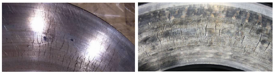
Figure 1), and it could be more serious in the long slope line. This problem sets a restriction against the further speed increasement, economic saving and security improvement of railway transportation, and even could cause catastrophic accidents. Therefore, the study of thermomechanical fatigue damage on the brake disc is of great importance from both academic and engineering perspectives.
There are different factors affecting fatigue failure [
8,
9] and several fatigue damage types can be detected on the brake disc (
Figure 1), i.e., heat checking (crackle), radial crack, circumferential crack and hot spot. Kasem et al. [
10] analyze the subsurface damage beneath the hot spots, plastic deformation and microcrack propagation are detected under the rubbing surface. Collignon et al. [
11] study the damage of brake discs and it is found that residual hoop tensile stress is relevant to radial microcracks. Honner et al. [
12] study the thermoelastic instability of the brake system, which is verified to be relevant for non-uniform temperature distribution. Yang et al. [
13] analyze the fatigue mechanism on the brake disc, fatigue cracking is observed in the interior and border of hot spots. Panier et al. [
14] propose a classification for hot spots and suggest a scenario of their occurrence by experimental methods. Kim et al. [
6] find that the maximum thermal stress under a variable pressure distribution is quite relevant with fatigue cracking. Wu et al. [
15] study the peak temperature and crack geometry evolution with the help of an inserted semi elliptical surface crack. Adamowica and Grzes [
16] study the brake disc temperature distribution, and it is found that the influence of convection cooling is significant in the brake release period. A review of the thermomechanical performance of brake discs with numerical and experimental approaches can be found in the work of Afzal and Mujeebu [
17].
According to previous research, the commonly used method for brake disc thermomechanical fatigue investigation is adopting the distribution and amplitude of temperature, stress and strain items. However, due to the rotating movement, the thermomechanical fatigue should belong to multiaxial fatigue damage [
18], which is complex with numerous influencing factors [
19]. Regrettably, the multiaxial feature of brake disc thermomechanical fatigue is ignored at this moment; this simplification might lead to an underestimation in the thermomechanical fatigue damage and a blur in the thermomechanical fatigue mechanism reveal.
Based on the analysis above, the study of multiaxial thermomechanical fatigue damage on the high-speed railway brake disc is insufficient. In this study, the thermomechanical fatigue damage of the brake disc will be studied with the help of a multiaxial fatigue model instead of using the distribution and amplitude of temperature, stress and strain items as fatigue indicators. A finite element simulation will be used to reproduce the multiaxial material response state under thermomechanical load. Afterward, a multiaxial fatigue model, recently proposed by the first author, will be adopted to analyze the multiaxial thermomechanical fatigue damage and out-of-phase failure status. Finally, the methodology for multiaxial thermomechanical fatigue evaluation will be proposed and the fatigue life prediction will be performed.
3. Multiaxial Fatigue Model
A fatigue model called the multiaxial fatigue space (referred as MFS criterion for convenience), recently proposed by the first author, is adopted to assess the multiaxial thermomechanical fatigue damage of the brake disc. The MFS criterion is validated by the fatigue test data of different materials under various loading conditions and displays a pleasant prediction capability, compared with other commonly used multiaxial fatigue models [
21]. A brief introduction is presented, and detailed information can be found in the corresponding reference [
21].
The fundamental assumption in the MFS criterion is that the changing of the material response state is the source of the fatigue damage. As shown in
Figure 3, subscripts T1 and T2 indicate different time points. σ and τ are normal and shear stresses, subscripts x and y represent the components following the global coordinates, and subscripts 1 and 2 mean the components following the principal directions. σ
1T1′ and σ
2T1′ indicate the response status at moment T2 following the principal directions of T1. C and R are the center and radius of Mohr circle, and A is twice the angle between the loading plane and the principal plane. It can be seen that the changing of the material state can be described by the changing of C, R and A. Therefore, the material response status is described by three parameters (
P1,
P2 and
P3), which are the equivalent shear parameter, equivalent normal parameter and out-of-phase parameter, respectively [
21]. The changing of them (three fatigue basic units, i.e.,
f1(
P1),
f2(
P2) and
f3(
P3)) can be used for fatigue damage evaluation, and the multiaxial fatigue space can be established by fatigue basic units (see
Figure 4) [
21]. The multiaxial fatigue parameter is described in Equation (6):
with
where
fn indicates a certain function,
P1 and
P2 are in-phase parameters and
P3 is out-of-phase parameter [
21],
N and
S indicate the normal and shear components on the critical plane (a couple of two orthogonal planes, noted by subscripts
C1 and
C2), stress, strain and energy components can be used as the adopted items,
is the out-of-phase angle, which represents the relative distortion deformation, and
is the limit value of the out-of-phase angle [
21]. It can be noticed that the MFS criterion belongs to the type of critical plane criterion.
According to the MFS criterion, the amplitude of parameter variation (changing of
P1,
P2 and
P3) is the foundational component in multiaxial fatigue space, which is consistent with the definition of fatigue damage. The influence of the mean scales the vector
OP in multiaxial fatigue space [
21]. Therefore, the multiaxial fatigue parameter in Equation (6) can be expressed by amplitude parameter (
) and mean parameter (
). See Equation (10):
with
where subscripts
a and
m indicate the amplitude and mean of corresponding parameter, subscripts
in and
out denote the in-phase and out-of-phase failure conditions,
k and
h are material-dependent coefficients, and
is the mean influence coefficient. Afterward, the predicted fatigue life (
) can be obtained by Equations (15) or (16), depending on the fatigue curve pattern:
where
A,
B,
C and
D are material-dependent coefficients with solid physical meaning in multiaxial fatigue space [
21].
It should be noticed that the original MFS criterion is established and validated in a 2-dimensional condition. With regard to 3-dimensional cases, the general formula is the same; the difference is in the determination of the critical plane. In this work, the directions of the maximum and the second maximum principal strain range are employed for critical plane determination. That is to say, the direction of the maximum principal strain range will be determined firstly. Afterward, the directions perpendicular to the maximum principal strain range will be checked to obtain the direction of the second maximum principal strain range. In this way, the issues of the 3-dimensional condition can be transformed into 2-dimensional cases and the MFS criterion can be used smoothly.
About the material dependent coefficients, normally the fatigue test is performed under mechanical fatigue loading instead of thermomechanical fatigue loading. The thermomechanical fatigue-dependent coefficients of the brake disc are not available at this moment. Thus, it is assumed that they are identical with the fatigue dependent coefficients of hot-rolled 45 steel [
21]. In order to present the methodology, this is a common strategy when the fatigue-related information is unavailable [
22,
23]. The adopted fatigue-dependent coefficients are listed in
Table 4. An accurate multiaxial thermomechanical fatigue evaluation of the brake disc can be performed following the proposed approach when the thermomechanical fatigue-dependent coefficients are collected in the future.
4. Results and Discussion
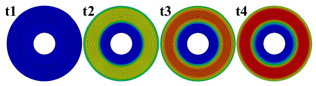
Considering the calculation efficiency, uniform loading is performed first, the calculation time is set as 500 s to have an overall response status, the highest temperature 454 °C occurs at 35 s, and the temperature distribution on the brake disc at four moments before the highest temperature time is demonstrated in
Figure 5. As discussed above, the multiaxial characters cannot be revealed with uniform loading. Rotating loading is needed for the multiaxial thermomechanical fatigue evaluation. According to the results with uniform loading, it can be seen that the temperature increases significantly and reaches above 400 °C in the first 20 s. Thus, the calculation time is set as 20 s with rotating loading so as to reduce the simulation time and result file size. The comparison between the results with rotating loading and uniform loading can be seen in
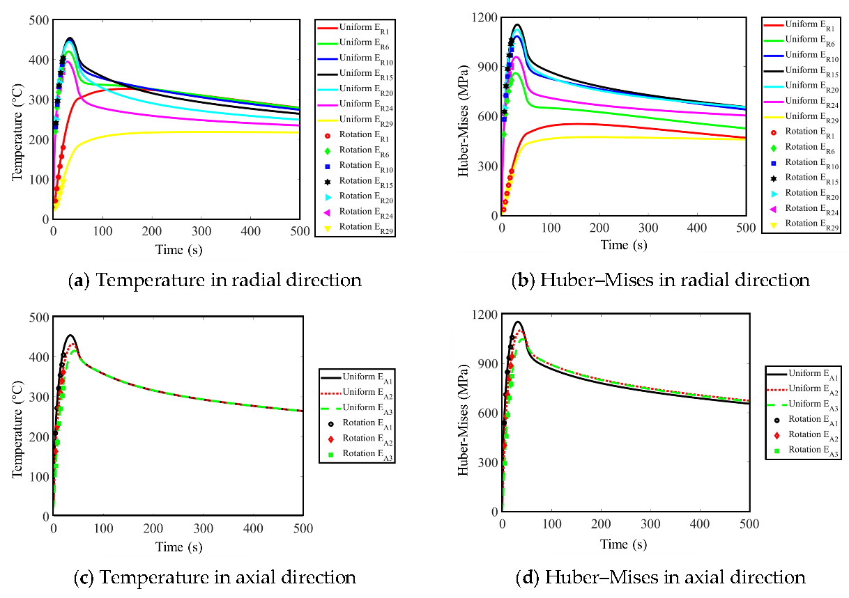
Figure 6.
It can be seen in
Figure 6 that the results manifestation is reasonable [
7,
17], which verifies the correctness of the calculation to a certain extent. The difference between the results with uniform and rotating loading is negligible. It can also be noticed that the heating time (50 s) is much shorter than the cooling time (much greater than 450 s) and the results variation during the heating process (see the changing of Huber–Mises results in the first 50 s in
Figure 6) is much more violent than that during the cooling process (see the Huber–Mises results from 50 s to 500 s in
Figure 6). Thus, as the changing of the material state during the heating process is used for fatigue evaluation, the calculation time is greatly reduced without losing much accuracy. To have a clear view about the multiaxial character of thermomechanical fatigue damage of the brake disc, the evolutions of the strain items with rotating loading can be seen in
Figure 7. It can be noticed clearly that the changing of shear strain is non-proportional, which indicates that the principal strain direction is changed during the braking process. It means that the thermomechanical fatigue damage of the brake disc not only belongs to the type of multiaxial fatigue damage, but also the out-of-phase failure status. The out-of-phase failure of the brake disc could be resulted from the mechanical interaction between the brake disc and the brake pad, or could be resulted from the influence of the brake disc structure. The reasons will be discussed in the future.
It is known that the changing of the material response state is critical for multiaxial fatigue analysis; the time increment needs to be small enough to capture the details of this changing. This makes the realization with rotating loading unfavorable because of the lengthy calculation time and huge resulting file size. Thus, an equivalent accelerated method (referred to as the equivalent method) is proposed. An amplification factor is used to scale the heat flux in order to reach the target temperature with only one rotation. In order to validate equivalent method, the temperature with rotating loading at 20 s is used as the target temperature (406.73 °C). The accepted tolerance for the obtained temperature by equivalent method is 1%. The temperature distribution with equivalent method at different times in one rotation is shown in
Figure 8; the highest temperature is 406.38 °C.
It can be seen that the highest temperature by the equivalent method (406.38 °C) is close to that with rotating loading (406.73 °C). The position of the maximum temperature by the equivalent method is located at the average friction radius position (E
R15), which is the same as the rotating loading calculation. The comparison of the results among uniform loading, rotating loading and equivalent methods at the maximum temperature position is shown in
Table 5. It can be seen that the temperature, thermal strain and Huber–Mises stress are approximately equal with each other. The results with rotating loading is used as reference. The temperature and strain with the equivalent method are quite satisfactory and the relative error is less than 0.1%. The difference of Huber–Mises stress is around 5% because of the history effect and constraint from the extrusion by the surrounding elements. In general, the results with the equivalent method are acceptable and strain items are used for the fatigue evaluation with the MFS criterion.
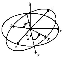
Regarding the multiaxial fatigue prediction capability with the equivalent method, the comparison with rotating loading is performed at different temperatures. Because the results of the finite element calculation are described in the global coordinate (coordinate xyz), coordinate transformation is executed with the help of Euler angles to get the material response status in coordinate XYZ (see
Figure 9). Here, zXZ rotation order is adopted for the coordinate transformation. Afterward, the MFS criterion can be adopted. The calculated fatigue parameter and relative error (defined in Equation (17)) are demonstrated in
Figure 10.
It can be seen that with the increasement of temperature, the relative error between the equivalent method and the rotating loading method is increased slowly, following a linear pattern, approximately. Based on this, the relationship function between the relative error (
) and temperature (
) can be written as Equation (18):
Now the multiaxial thermomechanical fatigue of the brake disc under the investigated braking operation condition can be assessed. Due to the fact that the calculation time with rotating loading is quite long, the maximum temperature with uniform loading is used as the target temperature (454 °C, see
Figure 6); the value of the fatigue parameter with the equivalent method can be obtained with this target temperature (see
Figure 10, blue point). Hereafter, the fatigue parameter value with rotating loading can be obtained with error correction (see
Figure 10, red point).
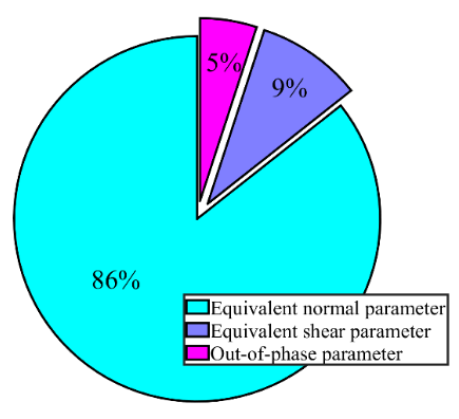
It is discussed above that the amplitudes and distributions of temperature, stress and strain items are not enough for accurate thermomechanical fatigue evaluation of the brake disc. Ignoring the influence of the multiaxial character and out-of-phase feature leads to an underestimation of the thermomechanical fatigue assessment for the brake disc. Based on the result with the rotating loading calculation, the contribution of the equivalent shear parameter, equivalent normal parameter and out-of-phase parameter (represented by
P1,
P2 and
P3 in the MFS criterion) to the total multiaxial thermomechanical fatigue parameter is demonstrated in
Figure 11. It can be seen that just using a uniaxial fatigue parameter causes at least 14% underestimation of the fatigue damage, while employing a multiaxial fatigue parameter without the consideration of the out-of-phase failure leads to an underestimation of 5%. It should be noticed that the relationship between the fatigue parameter and fatigue life is exponential, which means that an insignificant deviation in the fatigue parameter assessment leads to a significant predicted error of fatigue life.
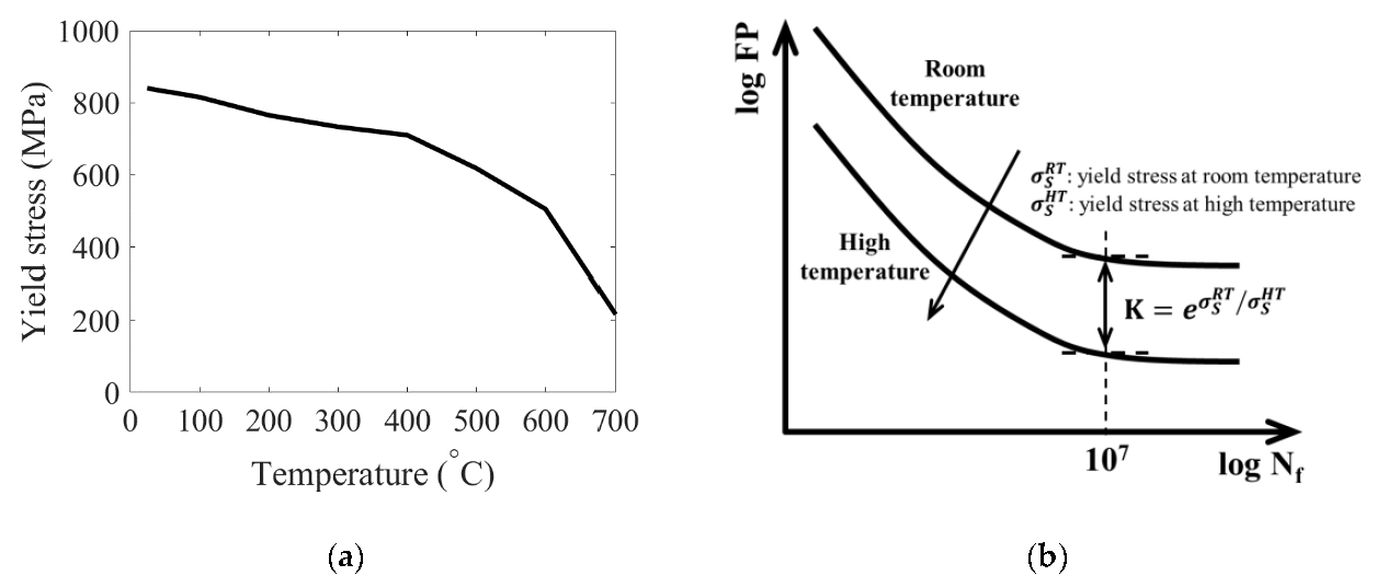
It is known that the material mechanical and fatigue characters change significantly with temperature [
24,
25,
26]. The material character under high temperature is not available at this moment. As there is an approximate linear relationship between the yield stress and fatigue limit [
27], the yield stress decreases exponentially with the increasing of the temperature, approximately (see
Figure 12a) [
15]. Thus, an exponential relationship between the fatigue limit and temperature is assumed in order to present the methodology in this work (see
Figure 12b). The corresponding fatigue curves at different temperatures can be obtained using extrapolation method with the help of the yield stress at different temperatures. The multiaxial thermomechanical fatigue life of the investigated brake disc under the employed braking operation condition can be obtained, which is about 2500 braking cycles. The accurate multiaxial thermomechanical fatigue life prediction can be obtained with the proposed methodology when the temperature related material fatigue characters become available in the future.


