
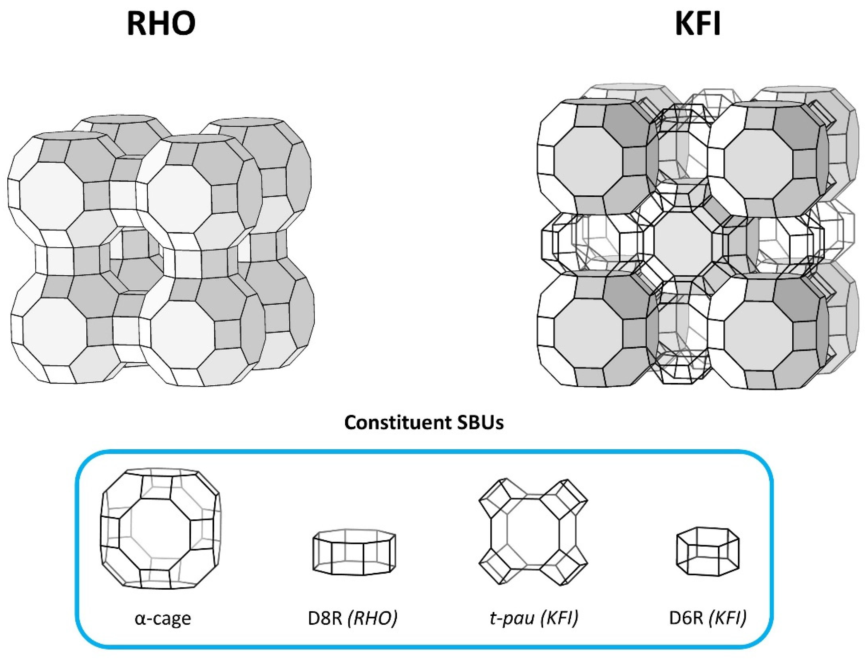
The Structure and Location of 18-Crown-6 Ether in Zeolites RHO and ZK-5


Abstract
:
1. Introduction
2. Methods
2.1. Sample Preparation
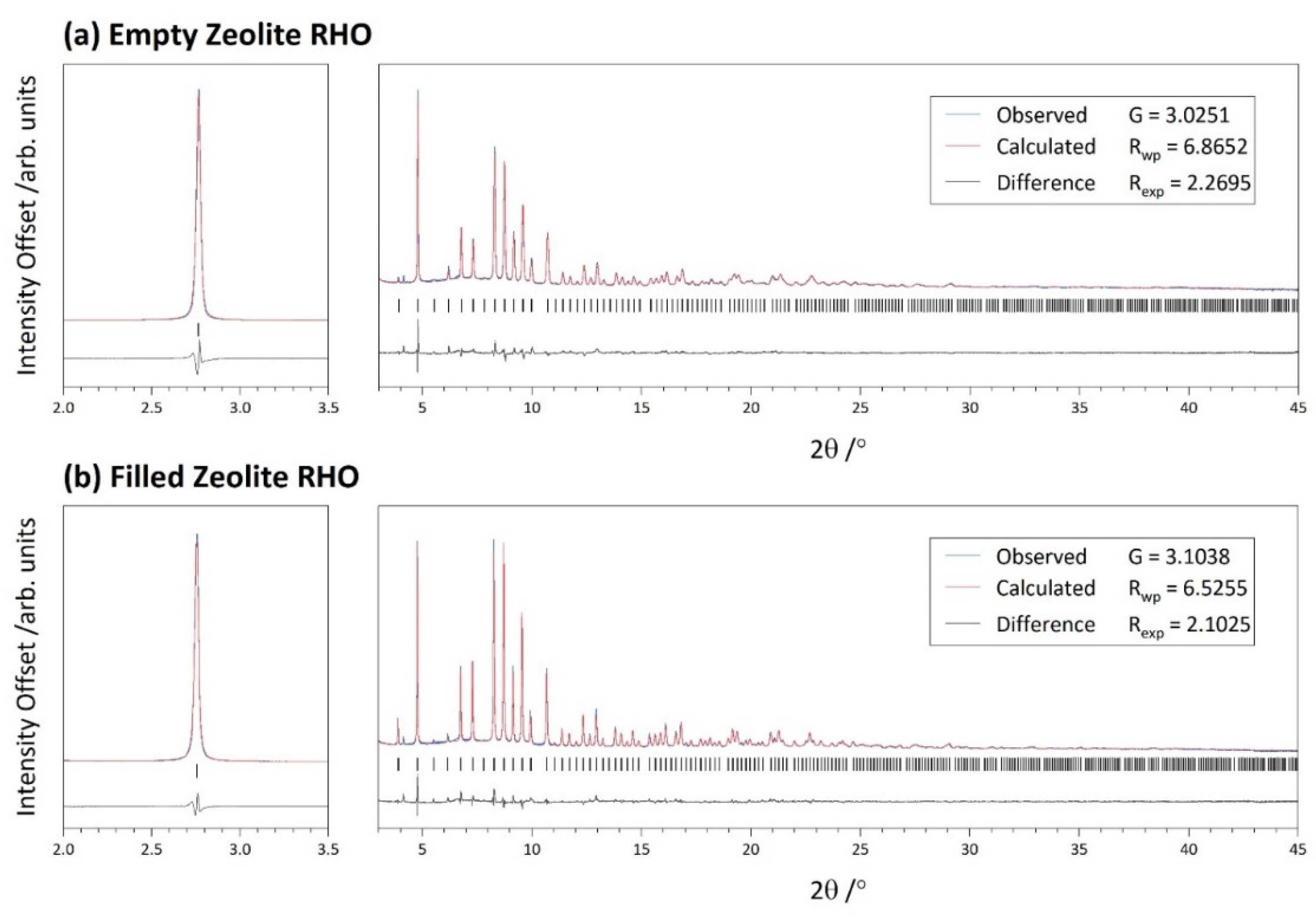
2.2. Zeolite RHO
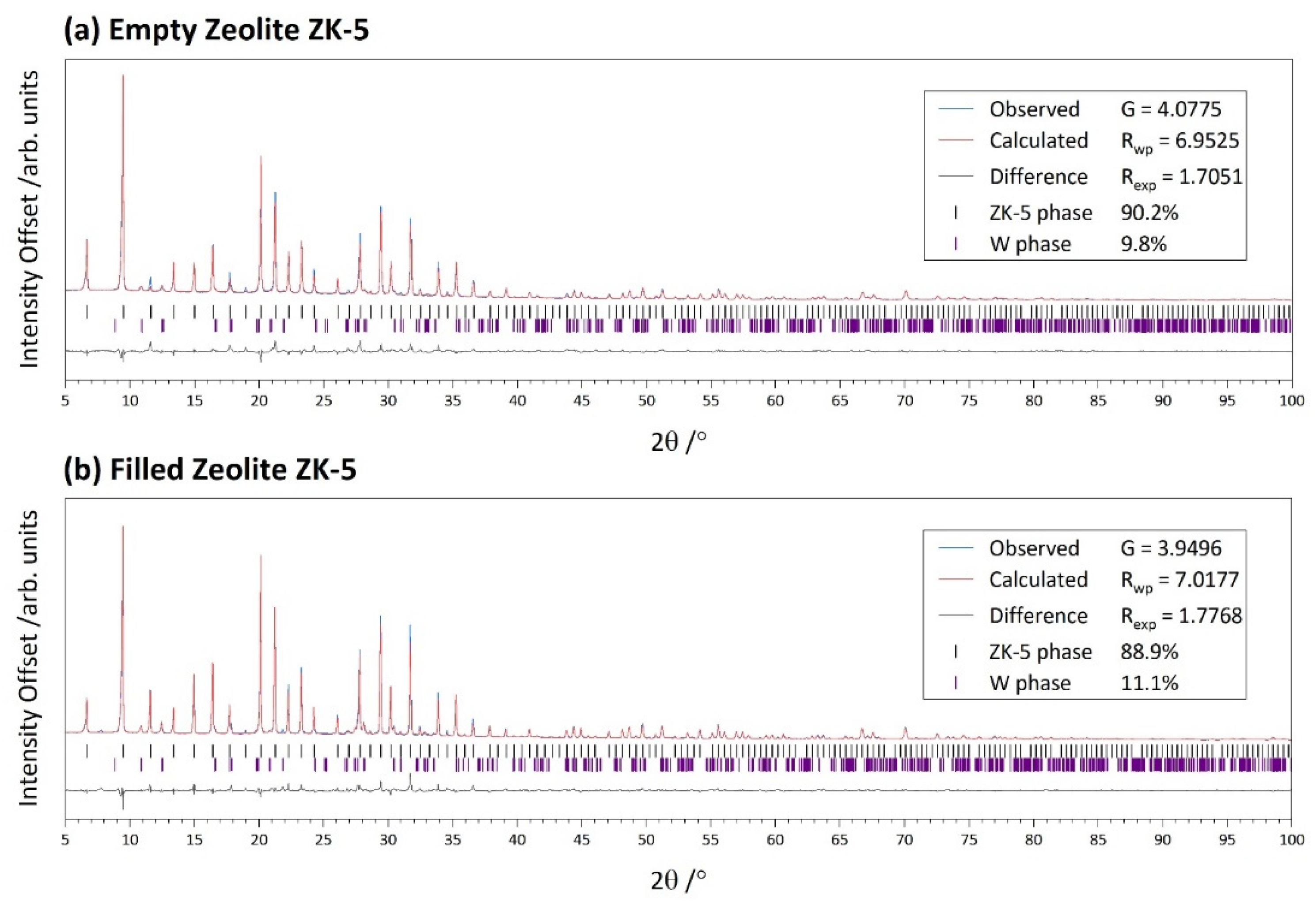
2.3. Zeolite ZK-5
2.4. Calcination and Dehydration
2.5. Thermogravimetry
2.6. Elemental Analysis
2.7. High Resolution Powder X-ray Diffraction
3. Results
3.1. Initial Characterisation
3.2. Zeolite RHO
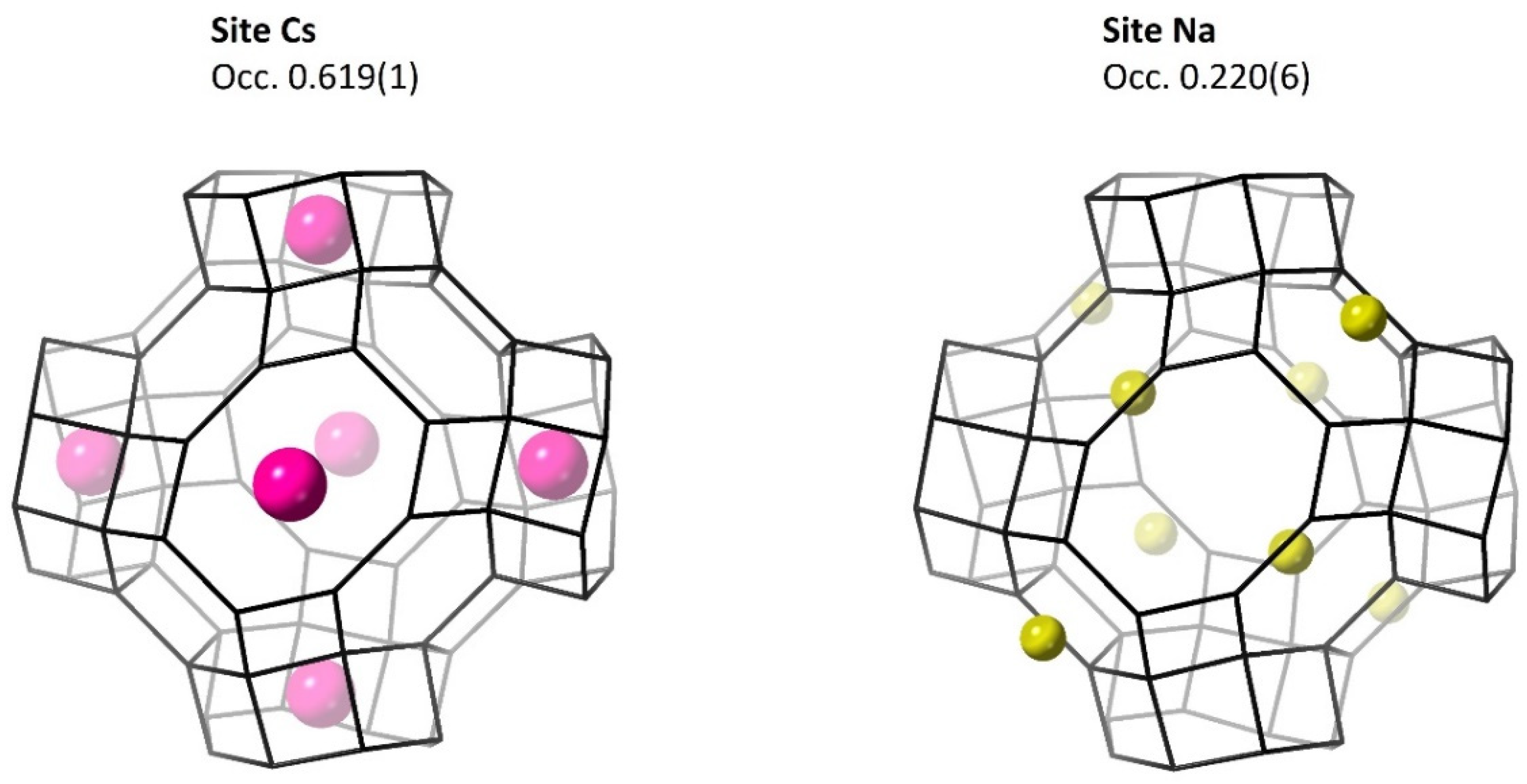
3.2.1. Metal Cations
3.2.2. The 18C6 Species
3.3. Zeolite ZK-5
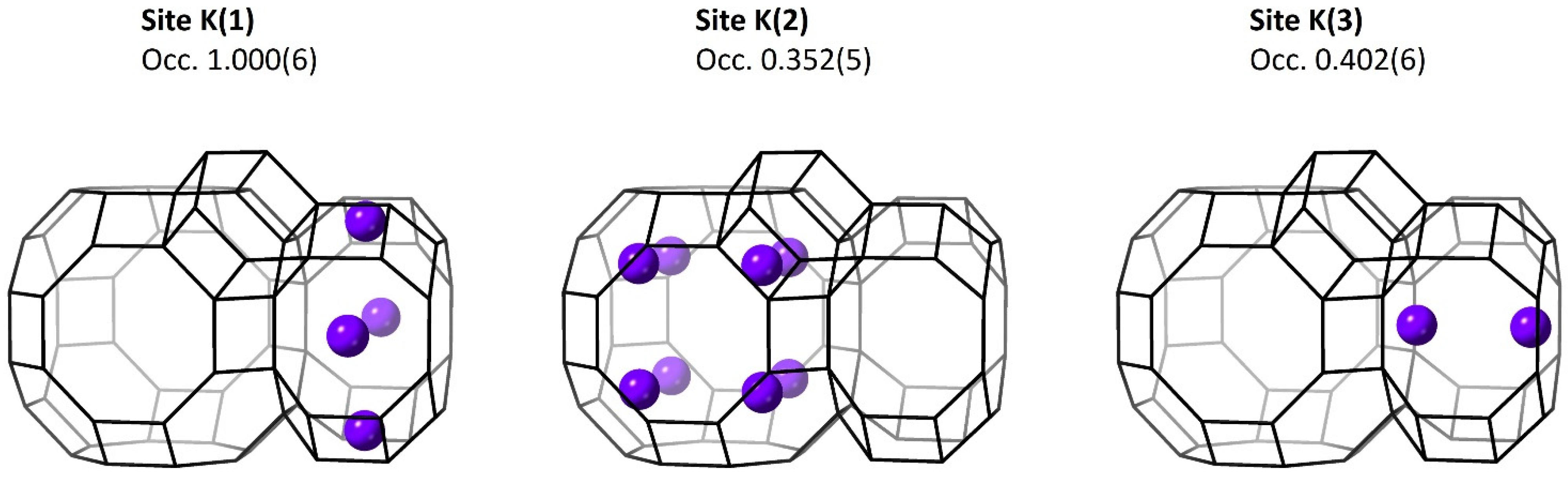
3.3.1. Metal Cations
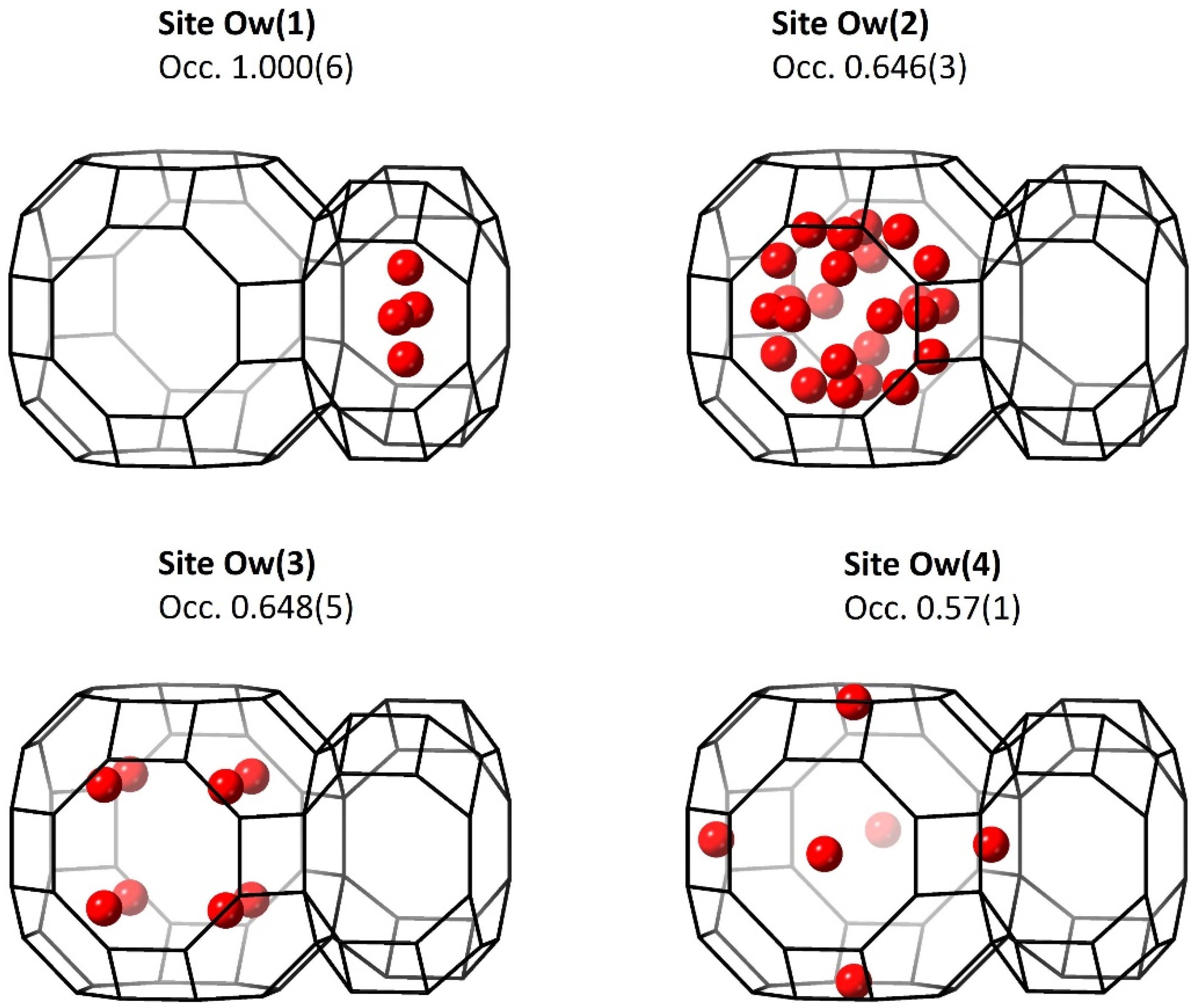
3.3.2. Water Molecules
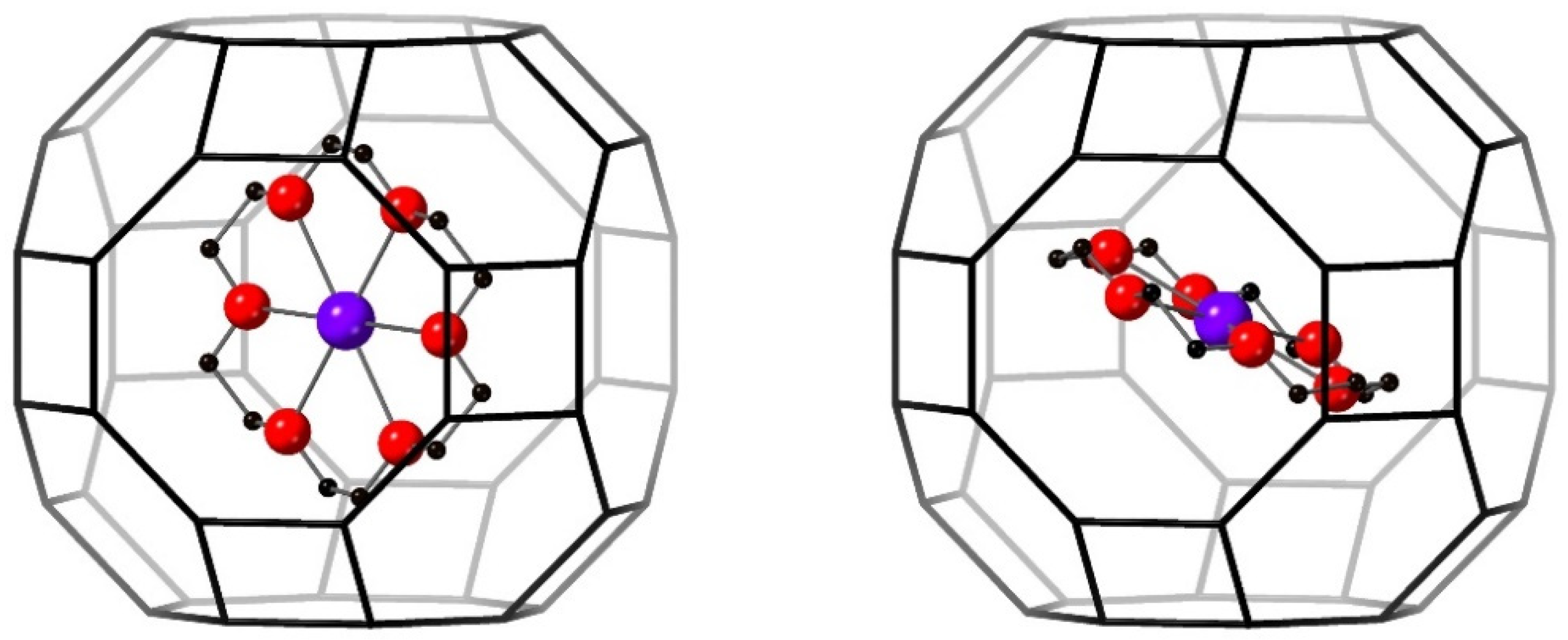
3.3.3. 18C6 Species
4. Discussion
5. Conclusions
Supplementary Materials
Author Contributions
Funding
Acknowledgments
Conflicts of Interest
References
- Barrer, R.M. Hydrothermal Chemistry of Zeolites; United States Edition ed.; Academic Press Inc. Ltd.: New York, NY, USA, 1982. [Google Scholar]
- Jacobs, P.A.; Flanigen, E.M.; Jansen, J.C.; van Bekkum, H. Introduction to Zeolite Science and Practice, 2nd ed.; Elsevier Science: Amsterdam, The Netherlands, 2010. [Google Scholar]
- Ipek, B.; Altiparmak, I. Remarkable isosteric heat of hydrogen adsorption on Cu(I)-exchanged SSZ-39. Int. J. Hydrog. Energy 2020, 45, 34972–34982. [Google Scholar] [CrossRef]
- Fisher, J.C.; Siriwardane, R.V.; Stevens, R.W., Jr. Zeolite-based process for CO2 capture from high-pressure, moderate-temperature gas streams. Ind. Eng. Chem. Res. 2011, 50, 13962–13968. [Google Scholar] [CrossRef]
- Dyer, A.; Hriljac, J.; Evans, N.; Stokes, I.; Rand, P.; Kellet, S.; Harjula, R.; Moller, T.; Maher, Z.; Heatlie-Branson, R.; et al. The use of columns of the zeolite clinoptilolite in the remediation of aqueous nuclear waste streams. J. Radioanal. Nucl. Chem. 2018, 318, 2473–2491. [Google Scholar] [CrossRef] [PubMed] [Green Version]
- Moore, P.B.; Smith, J.V. Archimedean polyhedra as the basis of tetrahedrally-coordinated frameworks. Mineral. Mag. J. Mineral. Soc. 1964, 33, 1008–1014. [Google Scholar] [CrossRef]
- Wilson, S.T. Templating in molecular sieve synthesis. In Verified Syntheses of Zeolitic Materials; Elsevier: Amsterdam, The Netherlands, 2001; pp. 27–31. [Google Scholar]
- Cundy, C.S.; Cox, P.A. The hydrothermal synthesis of zeolites: Precursors, intermediates and reaction mechanism. Microporous Mesoporous Mater. 2005, 82, 1–78. [Google Scholar] [CrossRef]
- Brunner, G. A proposal for a mechanism of nucleation in zeolite synthesis. Zeolites 1992, 12, 428–430. [Google Scholar] [CrossRef]
- Burkett, S.L.; Davis, M.E. Mechanism of structure direction in the synthesis of pure-silica zeolites. 2. Hydrophobic hydration and structural specificity. Chem. Mater. 1995, 7, 1453–1463. [Google Scholar] [CrossRef]
- Burkett, S.L.; Davis, M.E. Mechanisms of structure direction in the synthesis of pure-silica zeolites. 1. Synthesis of TPA/Si-ZSM-5. Chem. Mater. 1995, 7, 920–928. [Google Scholar] [CrossRef]
- Flanigen, E.M.; Bennett, J.; Grose, R.; Cohen, J.; Patton, R.; Kirchner, R.; Smith, J. Silicalite, a new hydrophobic crystalline silica molecular sieve. Nature 1978, 271, 512–516. [Google Scholar] [CrossRef]
- Oleksiak, M.D.; Rimer, J.D. Synthesis of zeolites in the absence of organic structure-directing agents: Factors governing crystal selection and polymorphism. Rev. Chem. Eng. 2014, 30, 1–49. [Google Scholar] [CrossRef]
- Baerlocher, C.; McCusker, L.B. Database of Zeolite Structures. Available online: http://www.iza-structure.org/databases/ (accessed on 9 January 2016).
- Lobo, R.F.; Zones, S.I.; Davis, M.E. Structure-direction in zeolite synthesis. Incl. Chem. Zeolites Nanoscale Mater. Des. 1995, 21, 47–78. [Google Scholar]
- Davis, M.E.; Lobo, R.F. Zeolite and molecular sieve synthesis. Chem. Mater. 1992, 4, 756–768. [Google Scholar] [CrossRef]
- Cox, P.A.; Casci, J.L.; Stevens, A. Molecular modelling of templated zeolite synthesis. Faraday Discuss. 1997, 106, 473–487. [Google Scholar] [CrossRef]
- Zones, S.I.; Nakagawa, Y. Boron-beta zeolite hydrothermal conversions: The influence of template structure and of boron concentration and source. Microporous Mater. 1994, 2, 543–555. [Google Scholar] [CrossRef]
- Fletcher, R.E.; Wells, S.A.; Leung, K.M.; Edwards, P.P.; Sartbaeva, A. Intrinsic flexibility of porous materials; theory, modelling and the flexibility window of the EMT zeolite framework. Acta Crystallogr. Sect. B Struct. Sci. Cryst. Eng. Mater. 2015, 71, 641–647. [Google Scholar] [CrossRef] [PubMed] [Green Version]
- Nearchou, A.; Cornelius, M.-L.U.; Skelton, J.M.; Jones, Z.L.; Cairns, A.B.; Collings, I.E.; Raithby, P.R.; Wells, S.A.; Sartbaeva, A. Intrinsic flexibility of the EMT zeolite framework under pressure. Molecules 2019, 24, 641. [Google Scholar] [CrossRef] [PubMed] [Green Version]
- Stevens, A.P.; Gorman, A.M.; Freeman, C.M.; Cox, P.A. Prediction of template location via a combined Monte Carlo–simulated annealing approach. J. Chem. Soc. Faraday Trans. 1996, 92, 2065–2073. [Google Scholar] [CrossRef]
- Lewis, D.W.; Willock, D.J.; Catlow, C.R.A.; Thomas, J.M.; Hutchings, G.J. De novo design of structure-directing agents for the synthesis of microporous solids. Nature 1996, 382, 604–606. [Google Scholar] [CrossRef]
- Lewis, D.W.; Freeman, C.M.; Catlow, C.R.A. Predicting the templating ability of organic additives for the synthesis of microporous materials. J. Phys. Chem. 1995, 99, 11194–11202. [Google Scholar] [CrossRef]
- Chatelain, T.; Patarin, J.; Farre, R.; Petigny, O.; Schulz, P. Synthesis and characterization of 18-crown-6 ether-containing KFI-type zeolite. Zeolites 1996, 17, 328–333. [Google Scholar] [CrossRef]
- Chatelain, T.; Patarin, J.; Soulard, M.; Guth, J.L.; Schulz, P. Synthesis and characterization of high-silica EMT and FAU zeolites prepared in the presence of crown-ethers with either ethylene-glycol or 1,3,5-trioxane. Zeolites 1995, 15, 90–96. [Google Scholar] [CrossRef]
- Chatelain, T.; Patarin, J.; Fousson, E.; Soulard, M.; Guth, J.L.; Schulz, P. Synthesis and characterization of high-silica zeolite-rho prepared in the presence of 18-crown-6 ether as organic template. Microporous Mater. 1995, 4, 231–238. [Google Scholar] [CrossRef]
- Robson, H. Verified Syntheses of Zeolitic Materials; Second Revised Edition ed.; Elsevier Science, B.V.: Amsterdam, The Netherlands, 2001; p. 265. [Google Scholar]
- Nearchou, A.; Raithby, P.R.; Sartbaeva, A. Systematic approaches towards template-free synthesis of EMT-type zeolites. Microporous Mesoporous Mater. 2018, 255, 261–270. [Google Scholar] [CrossRef] [Green Version]
- Baerlocher, C.; McCusker, L.B.; Chiappetta, R. Location of the 18-crown-6 template in EMC-2 (EMT) Rietveld refinement of the calcined and as-synthesised forms. Microporous Mater. 1994, 2, 269–280. [Google Scholar] [CrossRef]
- Terasaki, O.; Ohsuna, T.; Alfredsson, V.; Bovin, J.O.; Watanabe, D.; Carr, S.W.; Anderson, M.W. Observation of spatially correlated intergrowths of faujastic polytypes and the pure end members by high-resolution electron microscopy. Chem. Mater. 1993, 5, 452–458. [Google Scholar] [CrossRef]
- Ohsuna, T.; Terasaki, O.; Alfredsson, V.; Bovin, J.O.; Watanabe, D.; Carr, S.W.; Anderson, M.W. Observations on the role of crown ether templates in the formation of hexagonal and cubic polymorphs of zeolite Y. Proc. R. Soc. A-Math. Phys. Eng. Sci. 1996, 452, 715–740. [Google Scholar]
- Burkett, S.L.; Davis, M.E. Structure-directing effects in the crown ether-mediated synthesis of FAU and EMT zeolites. Microporous Mater. 1993, 1, 265–282. [Google Scholar] [CrossRef]
- Nearchou, A.; Armstrong, J.; Butler, K.T.; Raithby, P.R.; Sartbaeva, A. Differentiating the role of organic additives to assemble open framework aluminosilicates using INS spectroscopy. Phys. Chem. Chem. Phys. 2020, 22, 14177–14186. [Google Scholar] [CrossRef]
- Chatelain, T.; Patarin, J.; Brendle, E.; Dougnier, F.; Guth, J.L.; Schulz, P. Synthesis of high-silica FAU-, EMT-, RHO- and KFI-type zeolites in the presence of 18-crown-6 ether. Stud. Surf. Sci. Catal. 1997, 105, 173–180. [Google Scholar]
- Lippmaa, E.; Maegi, M.; Samoson, A.; Tarmak, M.; Engelhardt, G. Investigation of the structure of zeolites by solid-state high-resolution silicon-29 NMR spectroscopy. J. Am. Chem. Soc. 1981, 103, 4992–4996. [Google Scholar] [CrossRef]
- Coelho, A.A. TOPAS and TOPAS-Academic: An optimization program integrating computer algebra and crystallographic objects written in C++. J. Appl. Crystallogr. 2018, 51, 210–218. [Google Scholar] [CrossRef] [Green Version]
- Parise, J.B.; Cox, D.E. Structural changes occurring upon dehydration of zeolite Rho. A study using neutron powder diffraction and distance-least-squares structural modeling. J. Phys. Chem. 1984, 88, 1635–1640. [Google Scholar] [CrossRef]
- Parise, J.B.; Shannon, R.D.; Prince, E.; Cox, D. The crystal structures of the synthetic zeolites (Cs, K)-ZK5 and (Cs, D)-ZK5 determined from neutron powder diffraction data. Z. Für Krist.-Cryst. Mater. 1983, 165, 175–190. [Google Scholar] [CrossRef]
- Toby, B.H. R factors in Rietveld analysis: How good is good enough? Powder Diffr. 2006, 21, 67–70. [Google Scholar] [CrossRef] [Green Version]
- Merritt, E.A. Some Beq are more equivalent than others. Acta Crystallogr. Sect. A Found. Crystallogr. 2011, 67, 512–516. [Google Scholar] [CrossRef] [PubMed]
- Nearchou, A.; Castaing, R.; Raithby, P.R.; Sartbaeva, A. Zeolites fit for a crown: Studying organic-framework host-guest interactions through thermogravimetric techniques. Microporous Mesoporous Mater. 2020, 308, 110479. [Google Scholar] [CrossRef]
- Baerlocher, C.; McCusker, L.B.; Olson, D.H. Atlas of Zeolite Framework Types, 6th ed.; Elsevier: Amsterdam, The Netherlands, 2007; p. 405. [Google Scholar]
- Robson, H.E.; Shoemaker, D.P.; Ogilvie, R.A.; Manor, P.C. Synthesis and crystal-structure of zeolite Rho—A new zeolite related to Linde Type-A. Adv. Chem. Ser. 1973, 121, 106–115. [Google Scholar]
- Parise, J.B.; Gier, T.E.; Corbin, D.R.; Abrams, L.; Jorgensen, J.D.; Prince, E. Flexibility of the framework of zeolite Rho. Structural variation from 11 to 573 K. A study using neutron powder diffraction data. J. Phys. Chem. 1984, 88, 2303–2307. [Google Scholar] [CrossRef]
- Nearchou, A.; Cornelius, M.-L.U.; Jones, Z.L.; Collings, I.E.; Wells, S.A.; Raithby, P.R.; Sartbaeva, A. Pressure-Induced Symmetry Changes in Body-Centered Cubic Zeolites. R. Soc. Open Sci. 2019, 6, 182158. [Google Scholar] [CrossRef] [PubMed] [Green Version]
- Lee, Y.; Hriljac, J.A.; Vogt, T.; Parise, J.B.; Edmondson, M.J.; Anderson, P.A.; Corbin, D.R.; Nagai, T. Phase transition of zeolite RHO at high-pressure. J. Am. Chem. Soc. 2001, 123, 8418–8419. [Google Scholar] [CrossRef] [PubMed]
- Gagné, O.C.; Hawthorne, F.C. Bond-length distributions for ions bonded to oxygen: Alkali and alkaline-earth metals. Acta Crystallogr. Sect. B Struct. Sci. Cryst. Eng. Mater. 2016, 72, 602–625. [Google Scholar] [CrossRef] [PubMed] [Green Version]
- Meier, W.Μ.; Kokotailo, G.T. The crystal structure of synthetic zeolite ZK-5. Z. Krist.-Cryst. Mater. 1965, 121, 211–219. [Google Scholar] [CrossRef]
- Lievens, J.L.; Verduijn, J.P.; Mortier, W.J. Cation site energies in dehydrated KFI-type zeolites: D-NaKFI, d-NaHKFI, and d-KKFI. Zeolites 1992, 12, 690–697. [Google Scholar] [CrossRef]
- Treacy, M.M.; Higgins, J.B. Collection of Simulated XRD Powder Patterns for Zeolites, 5th ed.; Elsevier: Amsterdam, The Netherlands, 2007. [Google Scholar]
- Nearchou, A.; Sartbaeva, A. Influence of alkali metal cations on the formation of zeolites under hydrothermal conditions with no organic structure directing agents. Crystengcomm 2015, 17, 2496–2503. [Google Scholar] [CrossRef] [Green Version]
- Robson, H.E. Method for Preparing a Small Pore Synthetic Zeolite. U.S. Patent 3,720,753, 13 March 1973. [Google Scholar]
- Verduijn, J.P. Zeolite ZK-5. U.S. Patent 4,994,249, 19 February 1991. [Google Scholar]
- Liu, S.; Zhang, P.; Meng, X.; Liang, D.; Xiao, N.; Xiao, F.-S. Cesium-free synthesis of aluminosilicate RHO zeolite in the presence of cationic polymer. Microporous Mesoporous Mater. 2010, 132, 352–356. [Google Scholar] [CrossRef]
- McCusker, L.B.; Baerlocher, C. The Sixth International Zeolite Conference; Butterworths: Guildford, UK, 1983; p. 812. [Google Scholar]
- Barrer, R.M.; Barri, S.; Klinowski, J. Proceedings of the Fifth International Zeolite Conference, Heyden, London, 2–6 June 1980; p. 20.
- Araki, S.; Kiyohara, Y.; Tanaka, S.; Miyake, Y. Adsorption of carbon dioxide and nitrogen on zeolite rho prepared by hydrothermal synthesis using 18-crown-6 ether. J. Colloid Interface Sci. 2012, 388, 185–190. [Google Scholar] [CrossRef] [PubMed]
- Araki, S.; Kiyohara, Y.; Tanaka, S.; Miyake, Y. Crystallization process of zeolite rho prepared by hydrothermal synthesis using 18-crown-6 ether as organic template. J. Colloid Interface Sci. 2012, 376, 28–33. [Google Scholar] [CrossRef] [PubMed]
- Galli, E.; Gottardi, G.; Pongiluppi, D. The crystal structure of the zeolite merlinoite. Neues Jahrb. Mineral. Mon. 1979, 1–9. [Google Scholar]


| Zeolite | Al2O3 | Na2O | K2O | SrO | Cs2O | SiO2 | 18C6 | H2O |
|---|---|---|---|---|---|---|---|---|
| RHO | 1 | 1.8 | 0.3 | 10 | 0.50 | 100 | ||
| ZK-5 | 1 | 2.7 | 0.1 | 10 | 1.0 | 220 |
| Si/Al Ratio | TGA–Mass% | |||
|---|---|---|---|---|
| 29Si NMR | EDX | 18C6 | Water | |
| Zeolite RHO | 3.93 | 3.7(2) | 7.3(1) | 9.9(2) |
| Zeolite ZK-5 | 4.0(1) | 2.9(1) | 11.5(1) | |
| Symmetry | Unit Cell | Refinement | |||
|---|---|---|---|---|---|
| Cubic | /Å | 14.5450(1) | G | 3.0251 | |
| Rwp | 6.8652 | ||||
| Rexp | 2.2695 | ||||
| Atom | Occ. | Beq | |||
| Si | 0.2702(1) | 0.1220(1) | 0.4217(1) | 0.78(2) | 0.27(2) |
| Al | 0.2702(1) | 0.1220(1) | 0.4217(1) | 0.22(2) | 0.27(2) |
| O(1) | 0.2134(2) | 0.2134(2) | 0.3962(3) | 1 | 0.98(4) |
| O(2) | 0.1264(2) | 0.1264(2) | 0.6238(2) | 1 | 0.98(4) |
| O(3) | 0.0326(2) | 0.2055(2) | 0.3858(2) | 1 | 0.98(4) |
| Cs | 0 | 0 | 0.5 | 0.619(1) | 4.81(4) |
| Na | 0.3333 | 0.3333 | 0.3333 | 0.220(6) | 2.0(5) |
| Symmetry | Unit Cell | Refinement | |||
|---|---|---|---|---|---|
| Cubic | /Å | 14.58787(5) | G | 3.1038 | |
| Rwp | 6.5255 | ||||
| Rexp | 2.1025 | ||||
| Atom | Occ. | Beq | |||
| Si | 0.2704(1) | 0.1210(1) | 0.4215(1) | 0.78(2) | 0.31(2) |
| Al | 0.2704(1) | 0.1210(1) | 0.4215(1) | 0.22(2) | 0.31(2) |
| O(1) | 0.2127(1) | 0.2127(1) | 0.4005(2) | 1 | 0.70(3) |
| O(2) | 0.1274(1) | 0.1274(1) | 0.6254(2) | 1 | 0.70(3) |
| O(3) | 0.0287(1) | 0.2105(1) | 0.3853(1) | 1 | 0.70(3) |
| Cs | 0 | 0 | 0.5 | 0.697(1) | 4.79(3) |
| Na | 0.3132(6) | 0.3132(6) | 0.3132(6) | 0.229(5) | 1.4(4) |
| C(1) | 0.2215(1) | 0.0577(1) | 0.1020(1) | 0.0227(1) | 3.7(6) |
| C(2) | 0.1818(1) | −0.0072(1) | 0.1724(1) | 0.0227(1) | 3.7(6) |
| C(3) | 0.0416(1) | −0.0530(1) | 0.2415(1) | 0.0227(1) | 3.7(6) |
| C(4) | −0.0605(1) | −0.0343(1) | 0.2409(1) | 0.0227(1) | 3.7(6) |
| C(5) | −0.1945(1) | −0.0510(1) | 0.1498(1) | 0.0227(1) | 3.7(6) |
| C(6) | −0.2279(1) | −0.0867(1) | 0.0582(1) | 0.0227(1) | 3.7(6) |
| C(7) | 0.2279(1) | 0.0867(1) | −0.0582(1) | 0.0227(1) | 3.7(6) |
| C(8) | −0.2215(1) | −0.0577(1) | −0.1020(1) | 0.0227(1) | 3.7(6) |
| C(9) | 0.1945(1) | 0.0510(1) | −0.1498(1) | 0.0227(1) | 3.7(6) |
| C(10) | 0.0605(1) | 0.0343(1) | −0.2409(1) | 0.0227(1) | 3.7(6) |
| C(11) | −0.0416(1) | 0.0530(1) | −0.2415(1) | 0.0227(1) | 3.7(6) |
| C(12) | −0.1818(1) | 0.0072(1) | −0.1724(1) | 0.0227(1) | 3.7(6) |
| O(4) | 0.1898(1) | 0.0320(1) | 0.0132(1) | 0.0227(1) | 3.7(6) |
| O(5) | 0.0846(1) | 0.0024(1) | 0.1734(1) | 0.0227(1) | 3.7(6) |
| O(6) | −0.0976(1) | −0.0618(1) | 0.1547(1) | 0.0227(1) | 3.7(6) |
| O(7) | −0.1898(1) | −0.0320(1) | −0.0132(1) | 0.0227(1) | 3.7(6) |
| O(8) | 0.0976(1) | 0.0618(1) | −0.1547(1) | 0.0227(1) | 3.7(6) |
| O(9) | −0.0846(1) | −0.0024(1) | −0.1734(1) | 0.0227(1) | 3.7(6) |
| Symmetry | Unit Cell | Refinement | |||
|---|---|---|---|---|---|
| Cubic | /Å | 18.6816(1) | G | 4.0775 | |
| Rwp | 6.9525 | ||||
| Rexp | 1.7051 | ||||
| Atom | Occ. | Beq | |||
| Si | 0.0835(1) | 0.2014(1) | 0.3189(1) | 0.82(3) | 0.26(4) |
| Al | 0.0835(1) | 0.2014(1) | 0.3189(1) | 0.18(3) | 0.26(4) |
| O(1) | 0.1269(2) | 0.1269(2) | 0.3119(3) | 1 | 0.46(7) |
| O(2) | 0.2550(2) | 0.2550(2) | 0.4080(3) | 1 | 0.46(7) |
| O(3) | 0 | 0.1860(3) | 0.3329(3) | 1 | 0.46(7) |
| O(4) | 0.25 | 0.1124(2) | 0.3876(2) | 1 | 0.46(7) |
| K(1) | 0 | 0.25 | 0.5 | 1.000(6) | 3.2(1)) |
| K(2) | 0.15 | 0.15 | 0.15 | 0.352(5) | 3.2(1) |
| K(3) | 0 | 0 | 0.3588(7) | 0.402(6) | 3.2(1) |
| Ow(1) | 0.0931(5) | 0 | 0.5 | 1.000(6 | 18.0(5) |
| Ow(2) | 0.3333 | 0.4256(5) | 0.5 | 0.646(3) | 18.0(5) |
| Ow(3) | 0.1208(6) | 0.1208(6) | 0.1208(6) | 0.648(5) | 18.0(5) |
| Ow(4) | 0 | 0 | 0.300(2) | 0.57(1) | 18.0(5) |
| Symmetry | Unit Cell | Refinement | |||
|---|---|---|---|---|---|
| Cubic | /Å | 18.68867(7) | G | 3.9496 | |
| Rwp | 7.0177 | ||||
| Rexp | 1.7768 | ||||
| Atom | Occ. | Beq | |||
| Si | 0.0834(1) | 0.2019(1) | 0.3209(1) | 0.79(2) | 0.74(4) |
| Al | 0.0834(1) | 0.2019(1) | 0.3209(1) | 0.21(2) | 0.74(4) |
| O(1) | 0.1286(2) | 0.1286(2) | 0.3142(3) | 1 | 1.10(7) |
| O(2) | 0.2547(2) | 0.2547(2) | 0.4090(2) | 1 | 1.10(7) |
| O(3) | 0 | 0.1852(3) | 0.3329(3) | 1 | 1.10(7) |
| O(4) | 0.25 | 0.1115(2) | 0.3885(2) | 1 | 1.10(7) |
| K(1) | 0 | 0.25 | 0.5 | 1.000(4) | 4.4(1) |
| K(3) | 0 | 0 | 0.415(1) | 0.243(7) | 4.4(1) |
| Ow(1) | 01082(5) | 0 | 0.5 | 0.866(9) | 7.4(3) |
| Ow(3) | 0.1386(4) | 0.1386(4) | 0.1386(4) | 1.00(2) | 7.4(3) |
| Ow(4) | 0 | 0 | 0.3317(8) | 0.96(1) | 7.4(3) |
| C(1) | 0.0318(1) | 0.0431(1) | 0.1882(1) | 0.0276(2) | 15.5(8) |
| C(2) | −0.0211(1) | −0.0180(1) | 0.1937(1) | 0.0276(2) | 15.5(8) |
| C(3) | −0.1221(1) | −0.0695(1) | 0.1362(1) | 0.0276(2) | 15.5(8) |
| C(4) | −0.1714(1) | −0.0605(1) | 0.0725(1) | 0.0276(2) | 15.5(8) |
| C(5) | −0.1750(1) | −0.0688(1) | 0.0543(1) | 0.0276(2) | 15.5(8) |
| C(6) | −0.1293(1) | −0.0862(1) | 0.1189(1) | 0.0276(2) | 15.5(8) |
| C(7) | 0.1293(1) | 0.0862(1) | 0.1189(1) | 0.0276(2) | 15.5(8) |
| C(8) | −0.0318(1) | −0.0431(1) | −0.1882(1) | 0.0276(2) | 15.5(8) |
| C(9) | 0.1750(1) | 0.0688(1) | 0.0543(1) | 0.0276(2) | 15.5(8) |
| C(10) | 0.1714(1) | 0.0605(1) | −0.0725(1) | 0.0276(2) | 15.5(8) |
| C(11) | 0.1221(1) | 0.0695(1) | −0.1362(1) | 0.0276(2) | 15.5(8) |
| C(12) | 0.0211(1) | 0.0180(1) | −0.1937(1) | 0.0276(2) | 15.5(8) |
| K(4) | 0 | 0 | 0 | 0.653(9) | 4.4(1) |
| O(5) | 0.0752(1) | 0.0330(1) | 0.1263(1) | 0.0276(2) | 15.5(8) |
| O(6) | −0.0679(1) | −0.0159(1) | 0.1335(1) | 0.0276(2) | 15.5(8) |
| O(7) | −0.1318(1) | −0.0725(1) | 0.0084(1) | 0.0276(2) | 15.5(8) |
| O(8) | −0.0752(1) | −0.0330(1) | −0.1263(1) | 0.0276(2) | 15.5(8) |
| O(9) | 0.1318(1) | 0.0725(1) | −0.0084(1) | 0.0276(2) | 15.5(8) |
| O(10) | 0.0679(1) | 0.0159(1) | −0.1335(1) | 0.0276(2) | 15.5(8) |
Publisher’s Note: MDPI stays neutral with regard to jurisdictional claims in published maps and institutional affiliations. |
© 2022 by the authors. Licensee MDPI, Basel, Switzerland. This article is an open access article distributed under the terms and conditions of the Creative Commons Attribution (CC BY) license (https://creativecommons.org/licenses/by/4.0/).
Share and Cite
Nearchou, A.; Dejoie, C.; Raithby, P.R.; Sartbaeva, A. The Structure and Location of 18-Crown-6 Ether in Zeolites RHO and ZK-5. Chemistry 2022, 4, 168-184. https://doi.org/10.3390/chemistry4010015
Nearchou A, Dejoie C, Raithby PR, Sartbaeva A. The Structure and Location of 18-Crown-6 Ether in Zeolites RHO and ZK-5. Chemistry. 2022; 4(1):168-184. https://doi.org/10.3390/chemistry4010015
Chicago/Turabian StyleNearchou, Antony, Catherine Dejoie, Paul R. Raithby, and Asel Sartbaeva. 2022. "The Structure and Location of 18-Crown-6 Ether in Zeolites RHO and ZK-5" Chemistry 4, no. 1: 168-184. https://doi.org/10.3390/chemistry4010015
APA StyleNearchou, A., Dejoie, C., Raithby, P. R., & Sartbaeva, A. (2022). The Structure and Location of 18-Crown-6 Ether in Zeolites RHO and ZK-5. Chemistry, 4(1), 168-184. https://doi.org/10.3390/chemistry4010015