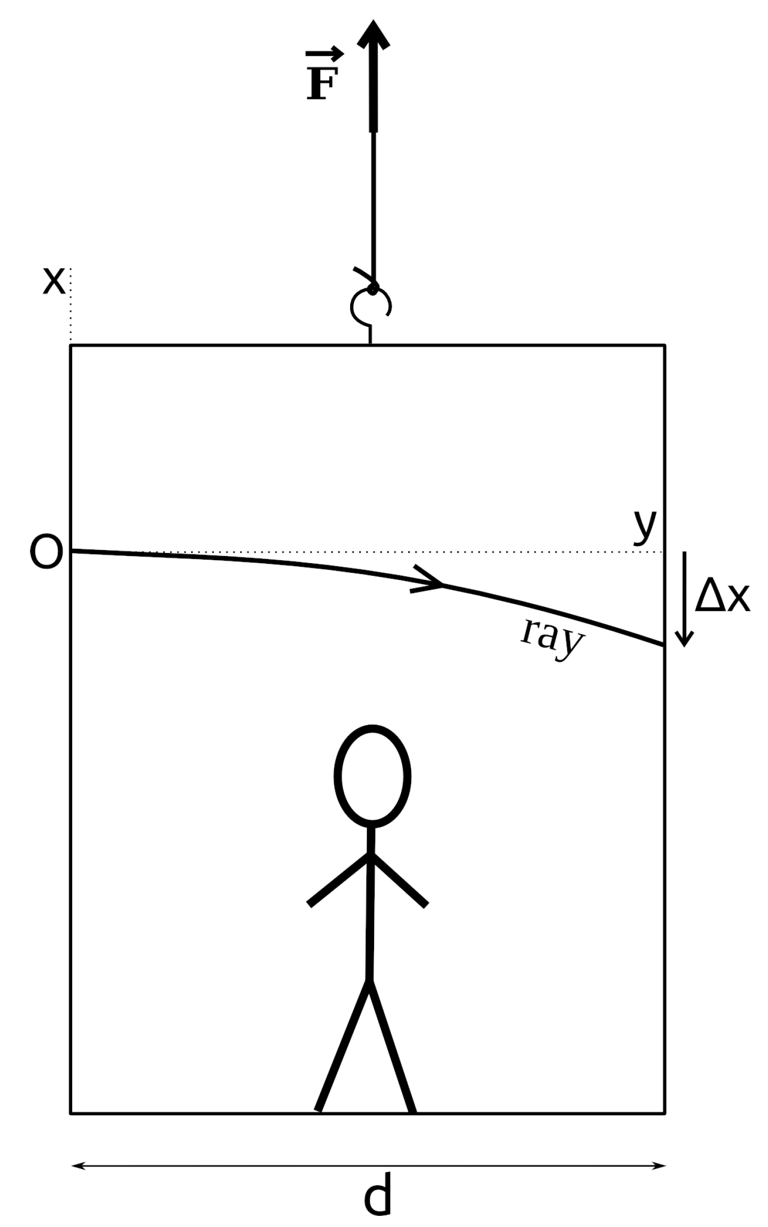
Figure 1.
The thought experiment in the Einstein’s elevator with a ray of light. Here, , d, x, and y denote the force exerted, the width of the box, and the vertical and lateral directions, respectively.
Figure 1.
The thought experiment in the Einstein’s elevator with a ray of light. Here, , d, x, and y denote the force exerted, the width of the box, and the vertical and lateral directions, respectively.
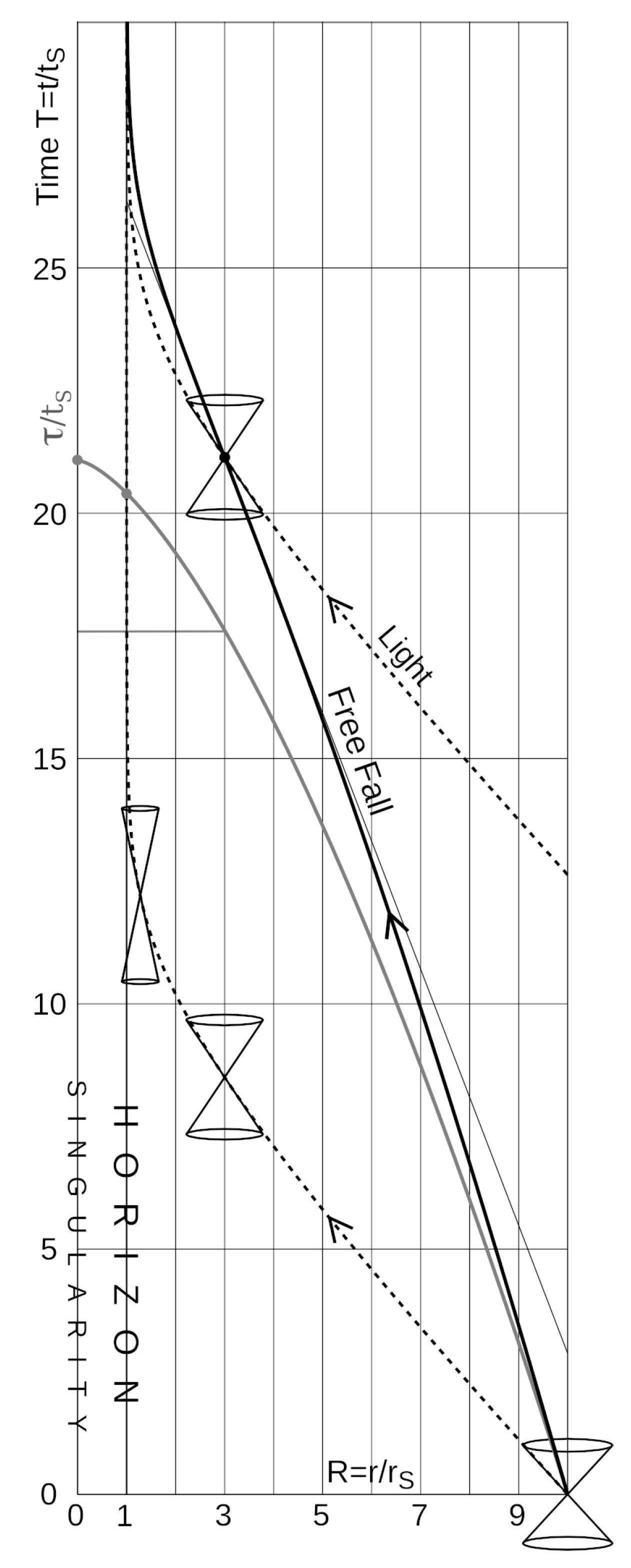
Figure 2.
Minkowski diagram of the rocket in the inertial reference frame
. The uniformly accelerated rocket has a hyperbolic worldline. In the reference frame
, the coordinate lines of
and
R are shown. In both cases, the coordinate lines of space and time are orthogonal. In this case, the rocket defines a rigid body [
2,
3,
4], with respect to which one can study the trajectory of the light rays. See
Section 2.2 for details.
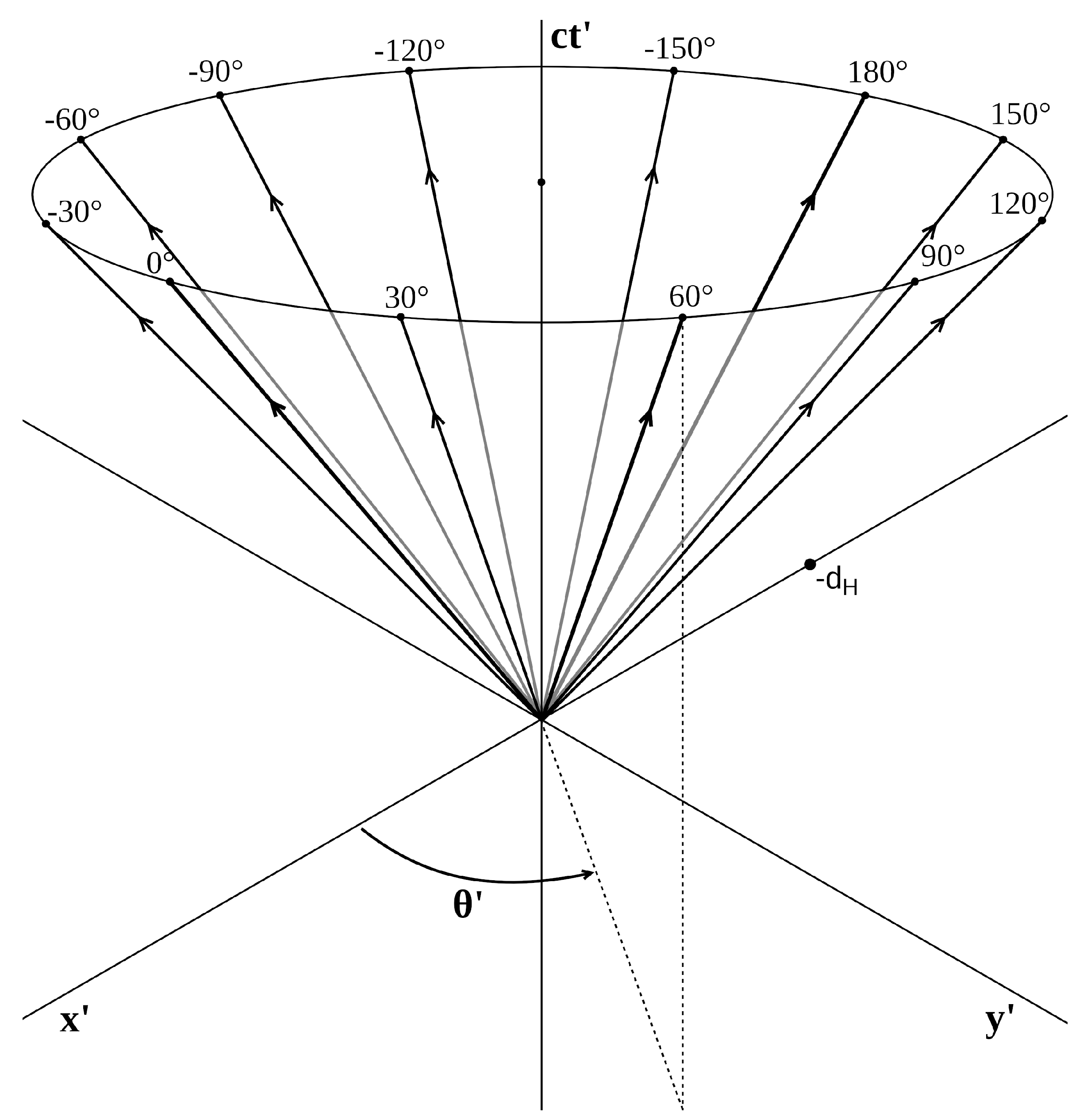
Figure 3.
The worldlines of 12 particular rays in a Minkowski diagram with as initial conditions.
Figure 3.
The worldlines of 12 particular rays in a Minkowski diagram with as initial conditions.
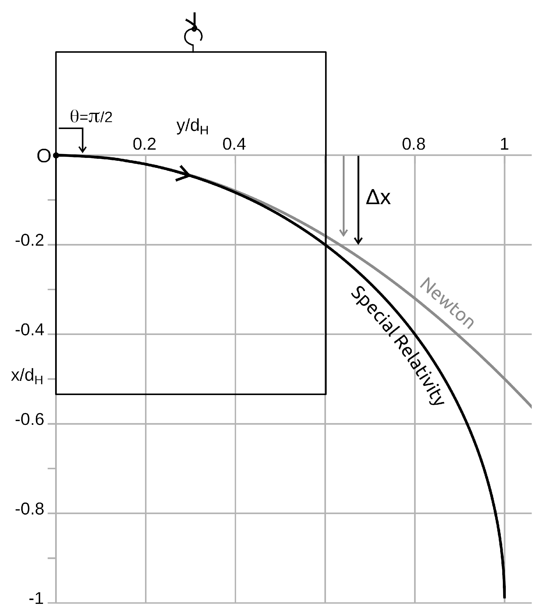
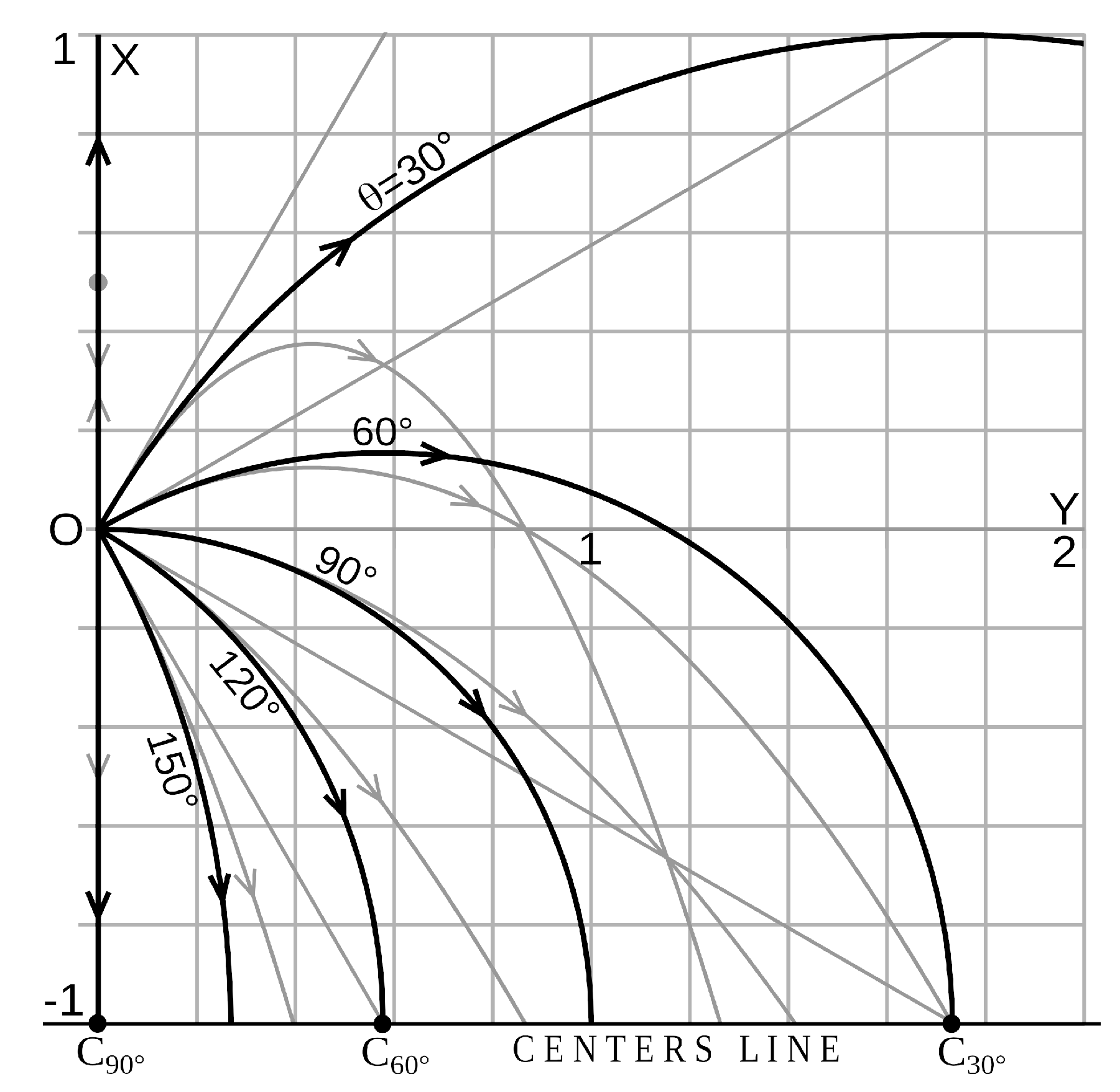
Figure 4.
The circular trajectory of the ray traced on a vertical wall of the elevator. The deviation is greater than that of Newton’s parabolic trajectory. At the level of the horizon the deviation is double.
Figure 4.
The circular trajectory of the ray traced on a vertical wall of the elevator. The deviation is greater than that of Newton’s parabolic trajectory. At the level of the horizon the deviation is double.
Figure 5.
In the plane, the trajectories of non-vertical light rays are portions of circles centered on the horizon. The rays thus arrive perpendicularly to the line of centers which is identified with the horizon. The grayed straight lines correspond to the inertial trajectories, in case the rocket is not accelerated. The gray parabolic lines are the Newtonian trajectories. For , a notable difference, the Newtonian rocket will overtake the ray, whereas the relativistic rocket cannot overtake the ray sent forward.
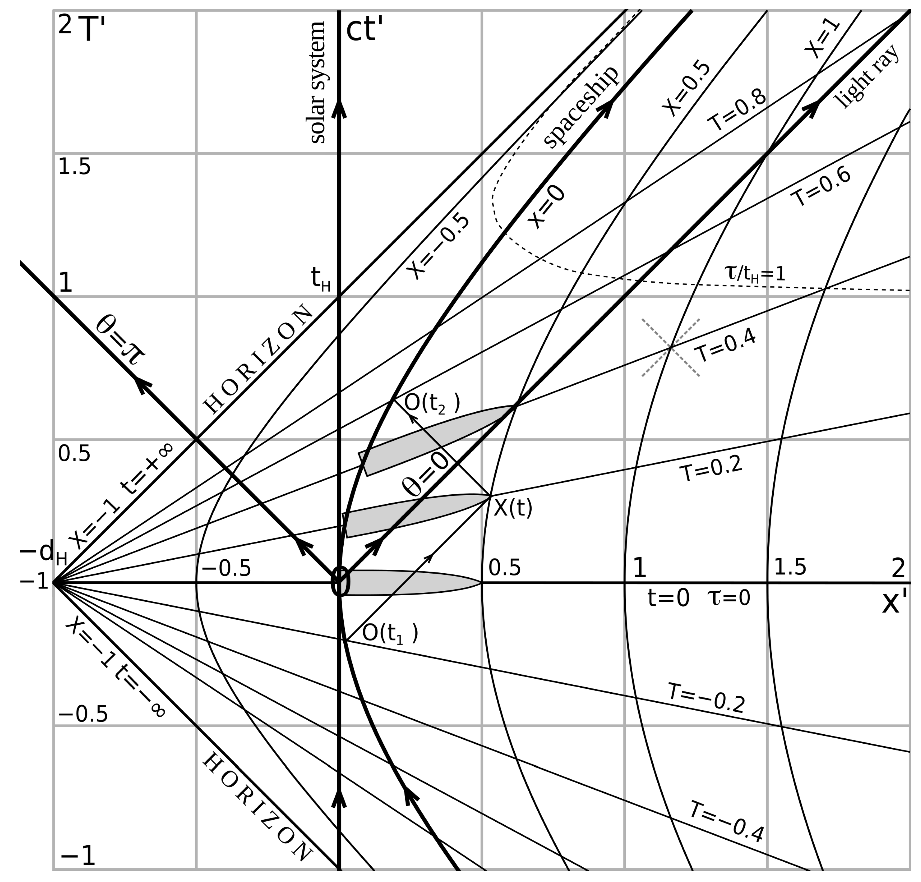
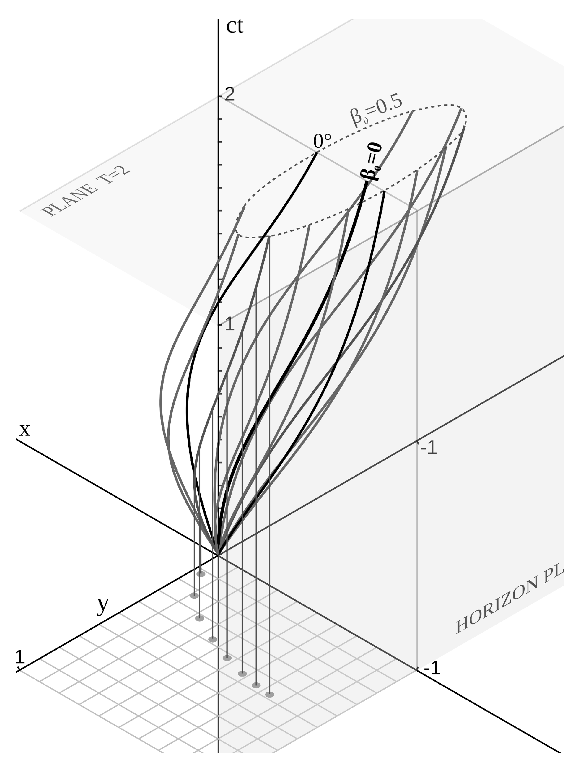
Figure 6.
The Minkowski diagram in the non-inertial reference frame . Apart from the limit case , all the light rays follow a partially helical worldline that asymptotically joins the horizon plane in an infinite time t. The maximum deviation tends towards the half-turn for a ray emitted in the direction close to .
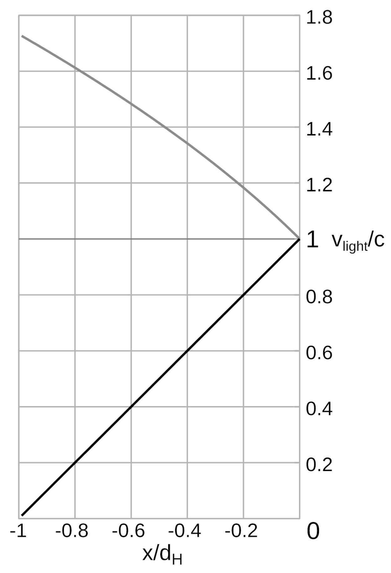
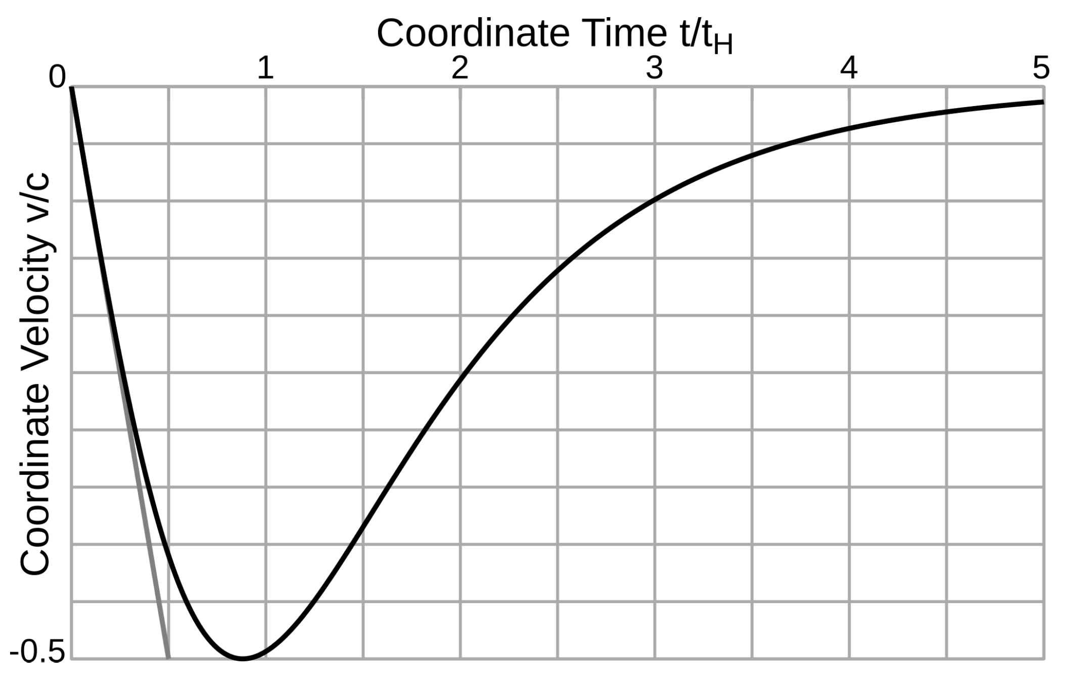
Figure 7.
The speed of light which decreases and tends towards zero in . In classical theory, there is no horizon and the speed of light increases.
Figure 7.
The speed of light which decreases and tends towards zero in . In classical theory, there is no horizon and the speed of light increases.
Figure 8.
Two clocks A and B at the same level are synchronized with the radar method. A light beam is emitted by A, reflected in B by a catadioptric system, and, back in A after .
Figure 8.
Two clocks A and B at the same level are synchronized with the radar method. A light beam is emitted by A, reflected in B by a catadioptric system, and, back in A after .
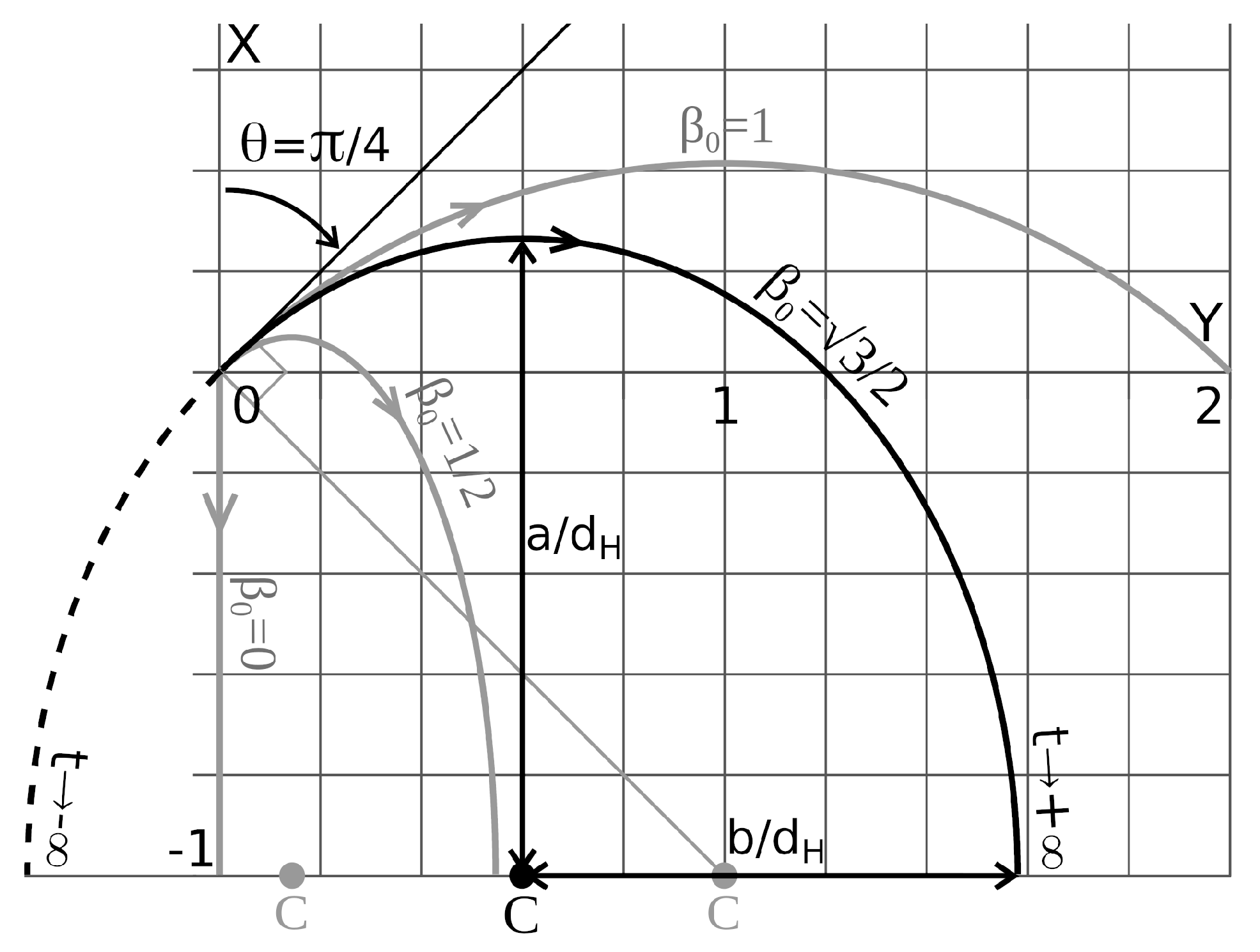
Figure 9.
In the plane, the trajectories of the particles are portions of ellipses with the center C on the horizon. The trajectories are perpendicular to the horizon line. The trajectory from to is a semi-ellipse, or a semi-circle for a zero-mass particle.
Figure 9.
In the plane, the trajectories of the particles are portions of ellipses with the center C on the horizon. The trajectories are perpendicular to the horizon line. The trajectory from to is a semi-ellipse, or a semi-circle for a zero-mass particle.
Figure 10.
The Minkowski diagram in the non-inertial reference frame . Worldlines for . In bold, the worldline for a particle released at rest. The intersection between a horizontal plane and the tubular worldsheet, formed by the set of worldlines for different s and a given , also forms an ellipse (dotted curve).
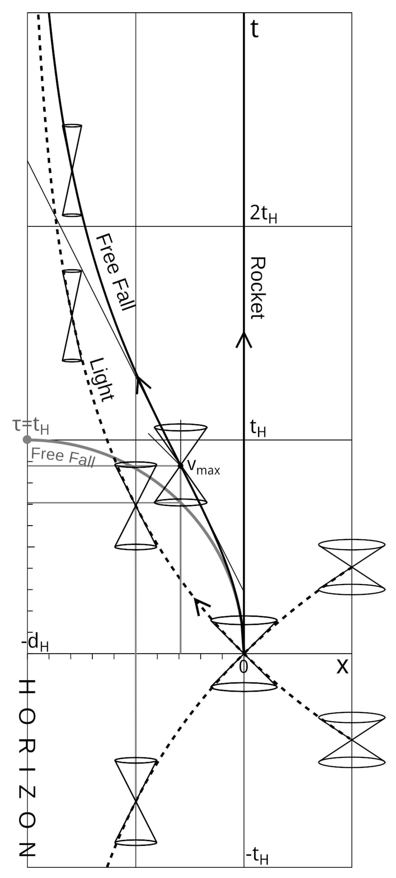
Figure 11.
Falling velocity of a particle, released at rest from O at . with the horizon time. In gray, the classical case.
Figure 11.
Falling velocity of a particle, released at rest from O at . with the horizon time. In gray, the classical case.
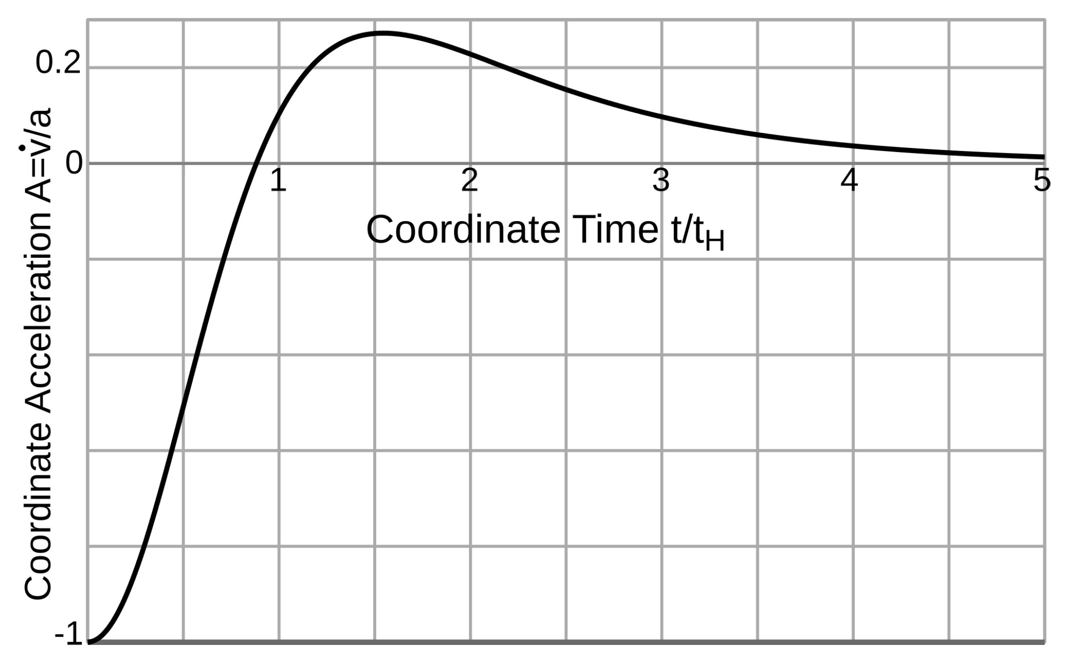
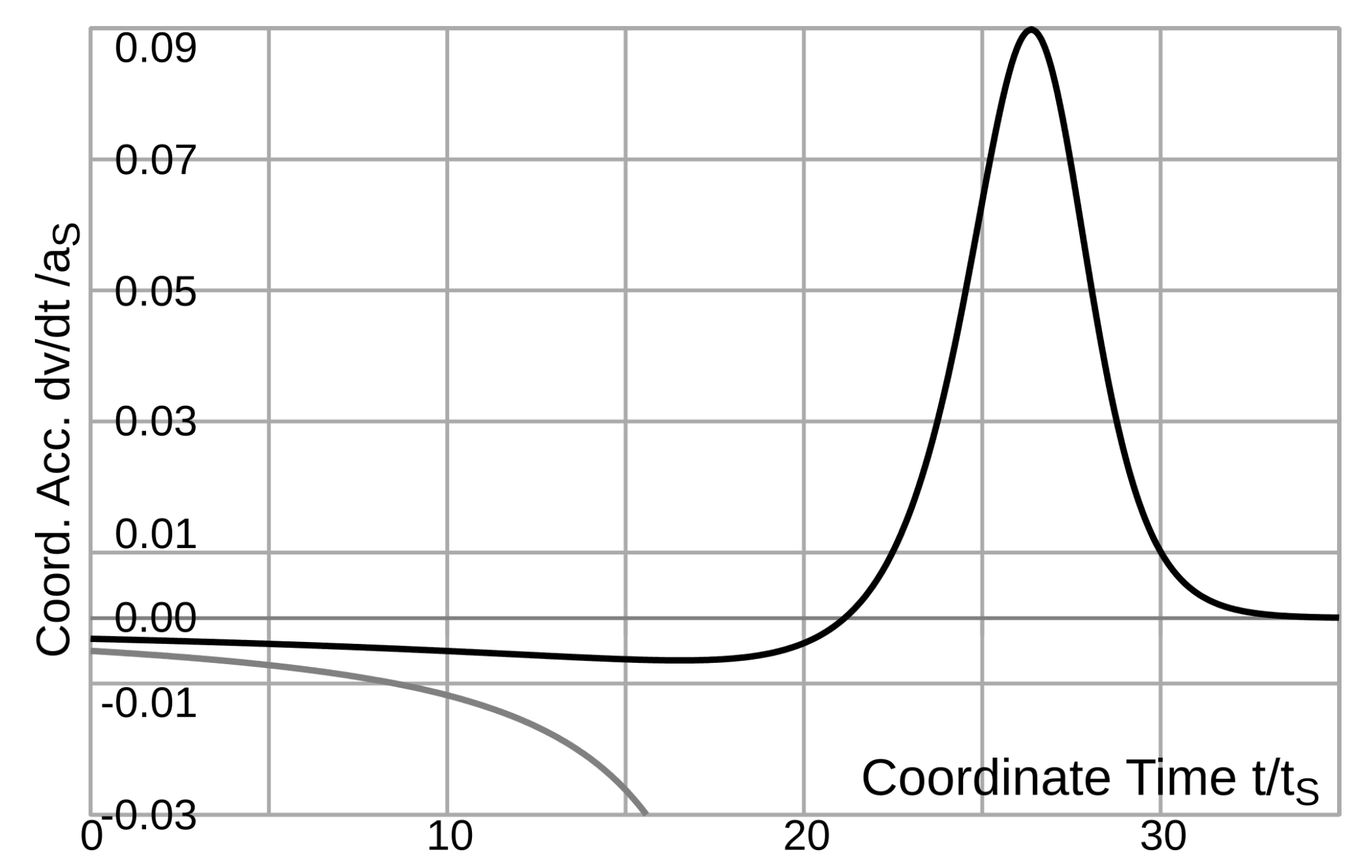
Figure 12.
Particle acceleration during a free fall in the uniformly accelerating reference frame.
Figure 12.
Particle acceleration during a free fall in the uniformly accelerating reference frame.
Figure 13.
The Minkowski diagram in the non-inertial frame . The cones indicate how the coordinate velocity of light varies with respect to c.
Figure 13.
The Minkowski diagram in the non-inertial frame . The cones indicate how the coordinate velocity of light varies with respect to c.
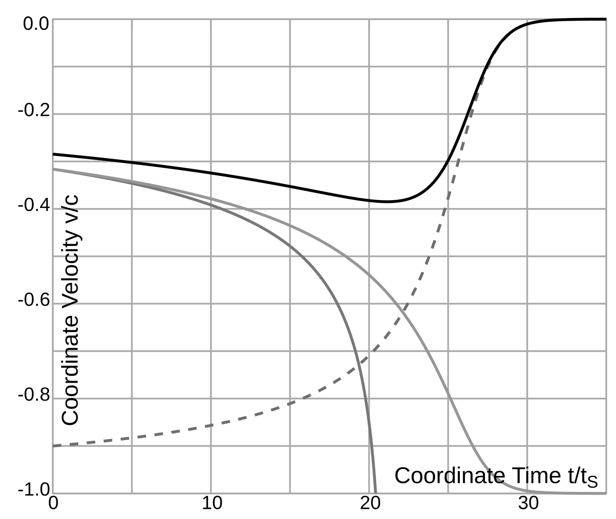
Figure 14.
Falling velocity of a particle, dropped without velocity from infinity. In dark gray, the curve according to Newton’s laws. Dotted, the speed of light. In light gray, the speed for a local observer.
Figure 14.
Falling velocity of a particle, dropped without velocity from infinity. In dark gray, the curve according to Newton’s laws. Dotted, the speed of light. In light gray, the speed for a local observer.
Figure 15.
The acceleration of the particle in radial fall towards a black hole. In gray, the classical curve.
Figure 15.
The acceleration of the particle in radial fall towards a black hole. In gray, the classical curve.
Figure 16.
Minkowski diagram in the Schwarzschild frame
[
15,
16]. See text for details.
Figure 16.
Minkowski diagram in the Schwarzschild frame
[
15,
16]. See text for details.
Figure 17.
Minkowski diagram for a vertical launch. draws a circle arc. See text for details.
Figure 17.
Minkowski diagram for a vertical launch. draws a circle arc. See text for details.
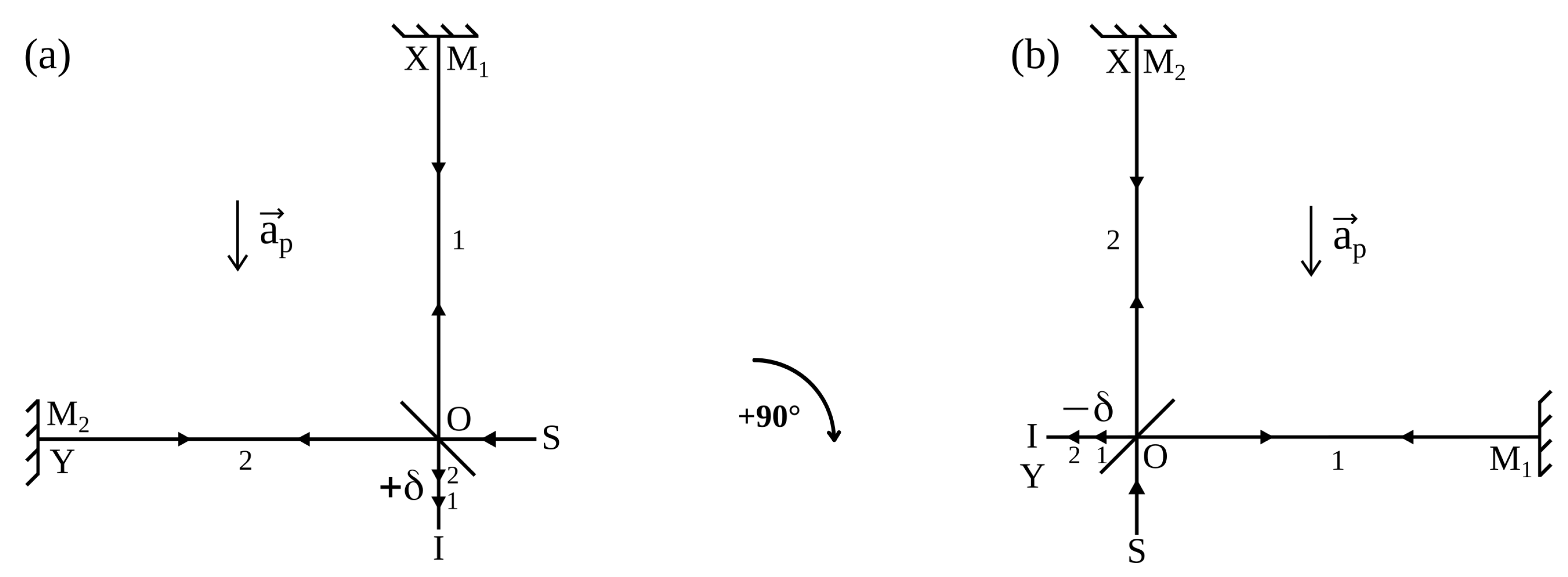
Figure 18.
Michelson interferometer with two arms and of same length l: a coherent light source S, such as a laser, emits a light ray which encounters at O a half-silvered mirror, so half of the light is transmitted to the mirror while the other half is reflected by . Both beams recombine at O and interfere on the detector I. In an inertial reference frame, there is no path length difference. (a) In the non-inertial frame, R, there is a proper acceleration along the downward direction, then the ray along X come back first and a path length difference appears. (b) The arm along the Y-axis rotates to the X-axis to take the place of the arm . The order of arrival of the rays on I is reversed.
Figure 19.
Minkowski diagram of the world lines of rays along the two arms of the interferometer for the configuration (a) of
Figure 18.
Figure 19.
Minkowski diagram of the world lines of rays along the two arms of the interferometer for the configuration (a) of
Figure 18.
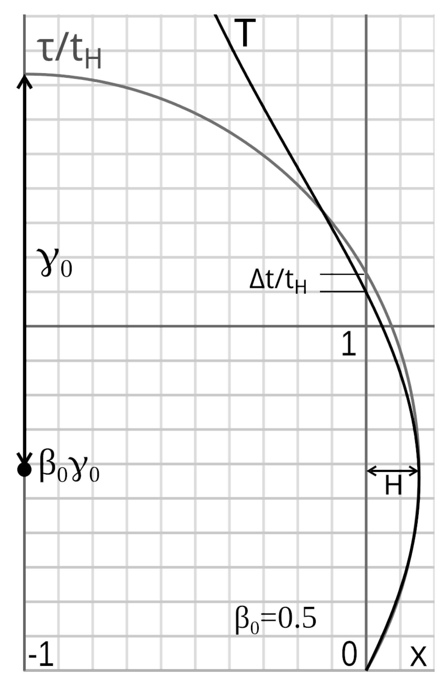
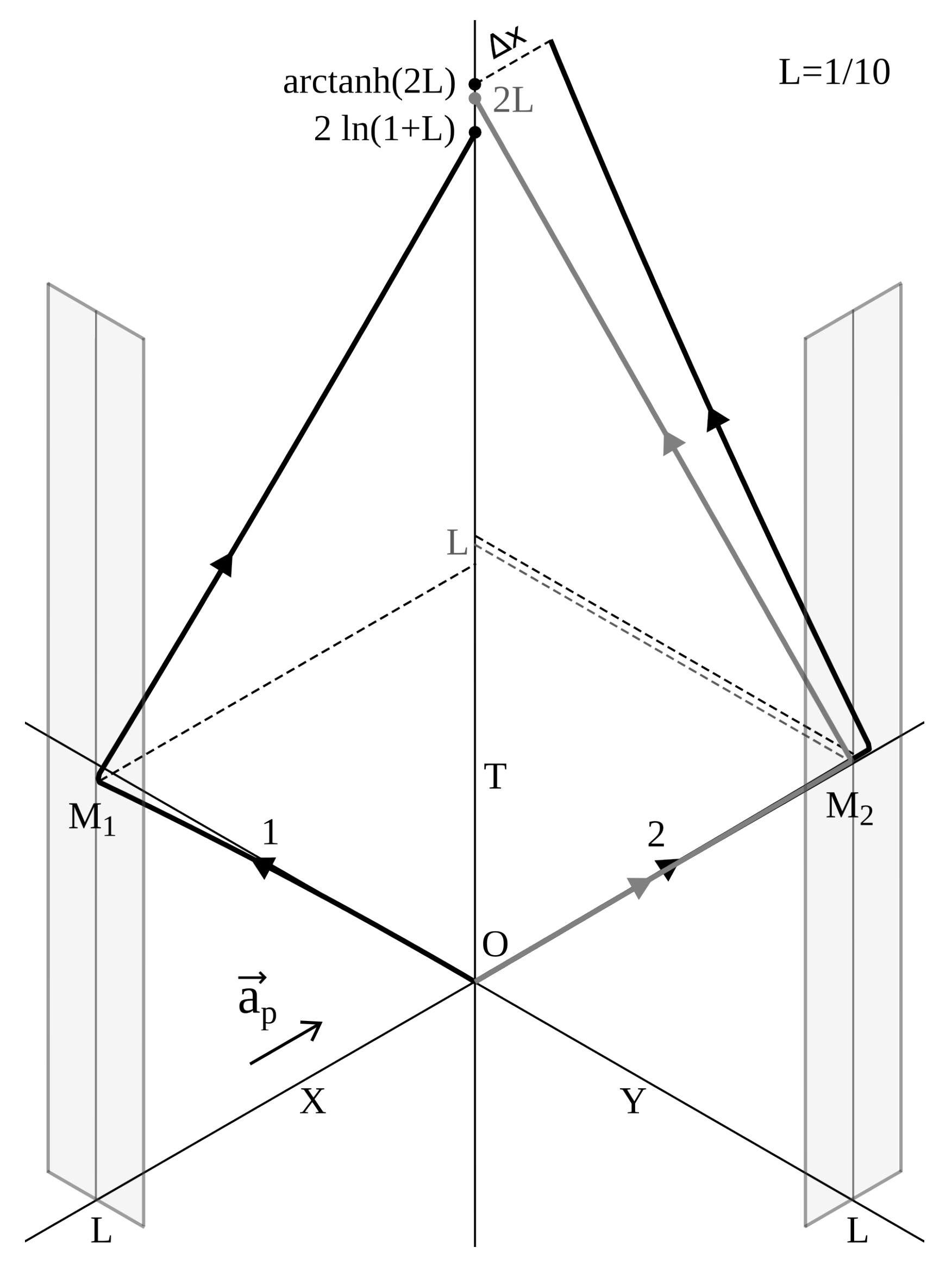
Figure 20.
In black, light signals: . In gray, there is an initial velocity such that: . Numerical values for : , . , , .
Figure 20.
In black, light signals: . In gray, there is an initial velocity such that: . Numerical values for : , . , , .
Figure 21.
Inertial point of View.
Figure 21.
Inertial point of View.


