Article

Study of Friction Force in Electrodynamic Rail Accelerator: Experiment and Interpretation Using FEM Modelling

1
Department of Electrotechnology, Czech Technical University, Technická 2, 166 27 Praha, Czech Republic
2
Department of Communication Technologies, Electronic Warfare and Radiolocation, University of Defense in Brno, Kounicova 65, 602 00 Brno, Czech Republic
3
Department of Weapons and Ammunition, University of Defense in Brno, Kounicova 65, 602 00 Brno, Czech Republic
4
Department of Electrical Power Engineering, Czech Technical University, Technická 2, 166 27 Praha, Czech Republic
*
Author to whom correspondence should be addressed.
Physics 2020, 2(4), 596-607; https://doi.org/10.3390/physics2040034
Submission received: 8 September 2020 / Revised: 19 October 2020 / Accepted: 20 October 2020 / Published: 25 October 2020
(This article belongs to the Section Applied Physics)

Abstract

:
The paper presents experimental data and a model of an electromagnetic rail accelerator. The model includes an equivalent circuit, magnetic field in the system and movement of the projectile (that is solved separately) which is computed numerically. The main results are compared with our experimental data and friction force during acceleration is evaluated.

1. Introduction

Electromagnetic accelerators nowadays represent an interesting and promising technology, both in military and civil areas [1]. While the development in the field has led to industrial applications already, there are still numerous challenges many of which can be aided by mathematical modelling [2,3,4], finite element method (FEM) in particular [5,6,7,8,9,10,11,12,13,14]. It has been shown since the 1990s that the inherent difficulties of the FEM solution, including the high spatial resolution required for current density in the vicinity of the projectile combined with much larger extent of the rails (which results in high number of mesh elements) or extremely rapid changes of the magnetic field and position, can be overcome and projectile velocities can be predicted for railguns in quantitative agreement with experiments [7,8,9]. Alternative electromagnetic accelerator designs, including the coilgun, also benefit from FEM modelling [15].
Although the design and construction of the device is seemingly not too complicated, one has to solve a number problems to achieve its efficient operation. One example of a serious challenge is the contact between the projectile and rails. The perpendicular force pushing the sides of the projectile to the rails must be neither too high, in order to avoid undesirably strong friction and subsequent heating of the parts in contact, nor too weak, which would lead to higher electric resistance of both parts resulting in unacceptable decrease of the field current and high energy losses. Furthermore, there is a gradual damage of the rails with the number of shots, which depends on the kinds and shapes of projectiles used as well as the design of the rails/barrel [16,17] which has been optimized by FEM modelling recently [6].
In this work we focus on evaluation of the friction force in a railgun device by comparing our experimental data (total force derived from the observed projectile position over time) with the electromagnetic driving force calculated by FEM assuming the experimental current at terminals of the simulated device. The friction force results in heat dissipation which reduces the efficiency and the endurance of the device; however, it is hard to model accurately or measure directly. Our study is motivated by the success of several earlier FEM simulations of the friction force [13,14]. We believe that the insight into the friction mechanism provided by our work can contribute to future optimized railgun designs.
Our analysis of the friction force is limited to low velocities (below 15 m/s) by our experimental equipment and results. However, the practical objective of our work is the minimization of rail degradation rather than maximization of the projectile velocity. The rail degradation is most significant at low velocities when the high current density and friction force lead to maximum heat dissipation [1,17]. Therefore, the relevant range of velocities is fully covered by our data.

2. Problem Formulation

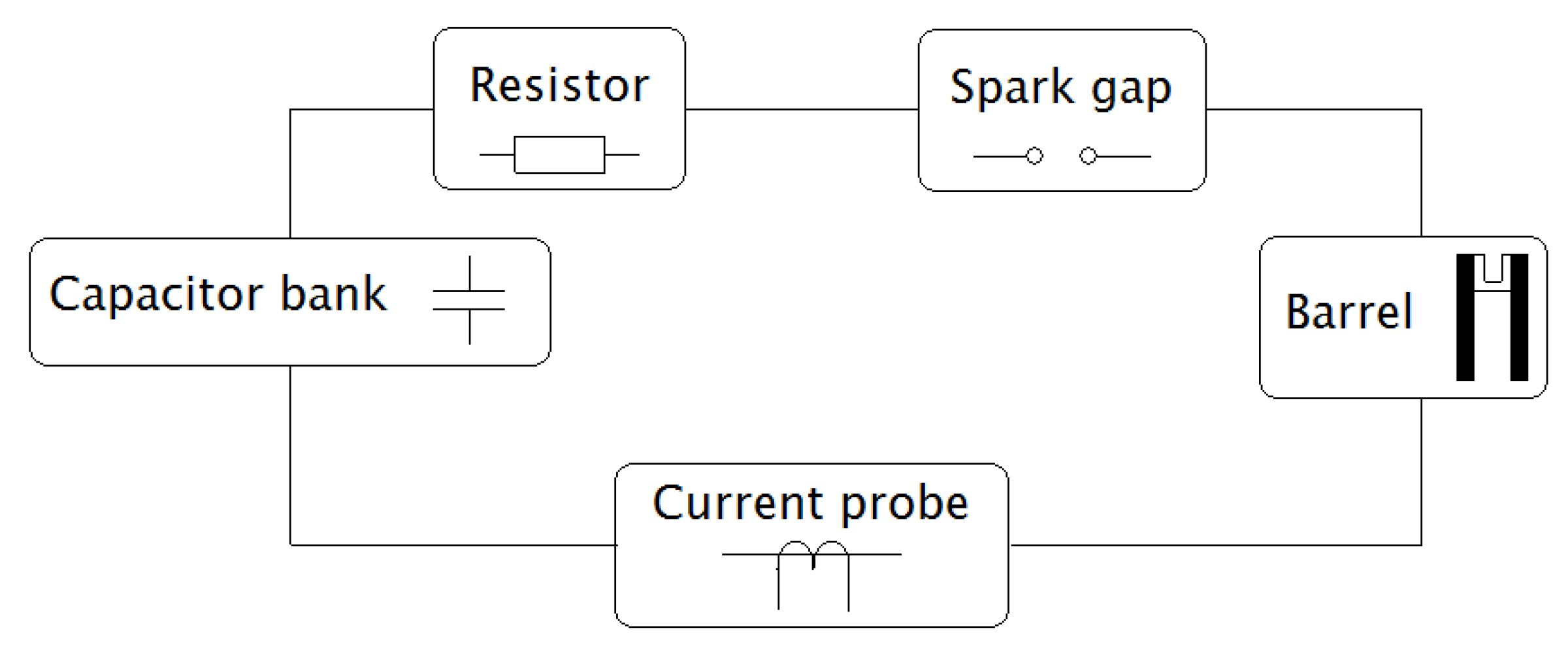
The device may be energized in several ways. We can mention, for instance, a flywheel generator, a homopolar generator, or a capacitor bank. The electric circuits and arrangements of rails can also differ one from another. This paper deals with the device installed in the Department of Weapons and Ammunition of the University of Defense in Brno that is powered by a capacitor bank (see Figure 1). The real arrangement of the whole system is schematically depicted in Figure 2.
As the systems of electrodynamic launching often differ one from another, it is not easy to build a general mathematical model [2,6,18]. The goal of the presented work was to propose a model of the device depicted in Figure 1 including the equivalent circuit and rails with the moving projectile, carry out the corresponding experiment, compare both results, and extract the friction force which is prohibitively complicated to obtain by simulation.
As for the numerical analysis, the procedure consists of the following steps:
  • Modelling the time-dependent equivalent circuit.
  • Finding the time dependence of the field current.
  • Modelling magnetic field in the system rails—projectile.
  • Determining the accelerating and drag forces on the projectile (using our experimental data).
  • Finding the time dependencies of its acceleration, velocity and trajectory, using the same data.
The order of particular steps starting from the measurement is the following:
  • Measuring the transient field current.
  • Measuring the time-dependent trajectory of the projectile.
  • Finding its velocity and acceleration.
  • Finding the total force acting on the projectile.
  • Separating the total force into the magnetic (accelerating) force and the friction force.

3. Modelling of Individual Parts of System

3.1. Equivalent Circuit

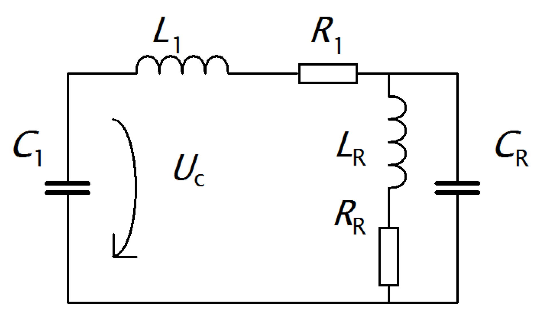
The aim of this subsection is to find the current at the terminal of the barrel as an analytical function of time. Instead of spline interpolation of the current that we measure at certain time points, we build an equivalent circuit for the system and find its parameters by direct measurement or by fitting to the experimental data. Even when the equivalent circuit (see Figure 2) is rather simple, it is necessary to take into account several parasitic elements (connected mainly with the capacitor and barrel) that may significantly influence its behavior. These elements have to be found using a comparison between the measured and modelled current and voltage responses. After several experiments, an acceptable and still sufficiently simple equivalent circuit with lumped parameters was selected as depicted in Figure 3. The significance of particular elements in Figure 3 follows from Table 1.
Here, the capacity C 1 of the capacitor bank is given by the manufacturer and this value corresponds well to the value verified by measurement. The same holds for the resistance R 1 that can be measured directly. Capacity C R of the rails was calculated from their geometrical arrangement (it is of order of 10−11 F). It is not constant, but it depends on the instantaneous position of the projectile. It was found that its presence has only a very small influence on the behavior of the circuit and can be neglected.
The values of L 1 , R R , and L R were determined by fitting of the voltage on the capacitor bank during the discharge and corresponding current passing through the circuit to our measured data. The values listed in Table 2 were determined by the least square fit method, for several different fixed positions of the projectile. This allowed us to analyze the dependence of R R ( x ) and L R ( x ) on position x. We assumed a linear dependence which provided a sufficient accuracy of the fitting as confirmed by Figure 4. All the parameters of the equivalent circuit are summarized in Table 2. The equivalent circuit obeys the differential equation for current i ( t ) in the form:
L 1   i ( t ) + R 1   i ( t ) + L R ( x )   i ´ ( t ) + R R ( x )   i ( t ) = 1 C 1   0 t i ( τ ) d τ   U 0 ,
where i = i t and the initial condition is i ( 0 ) = 0 . The right hand side is U c ( t ) =   1 C 1 0 t i ( τ )   d τ U 0 and U c ( t = 0 ) =   U 0 is a constant.
Similar results were found for the short circuit with x = l / 2 and x = l , l being the length of the rails (l = 1 m). The differences between particular curves do not exceed 2%.
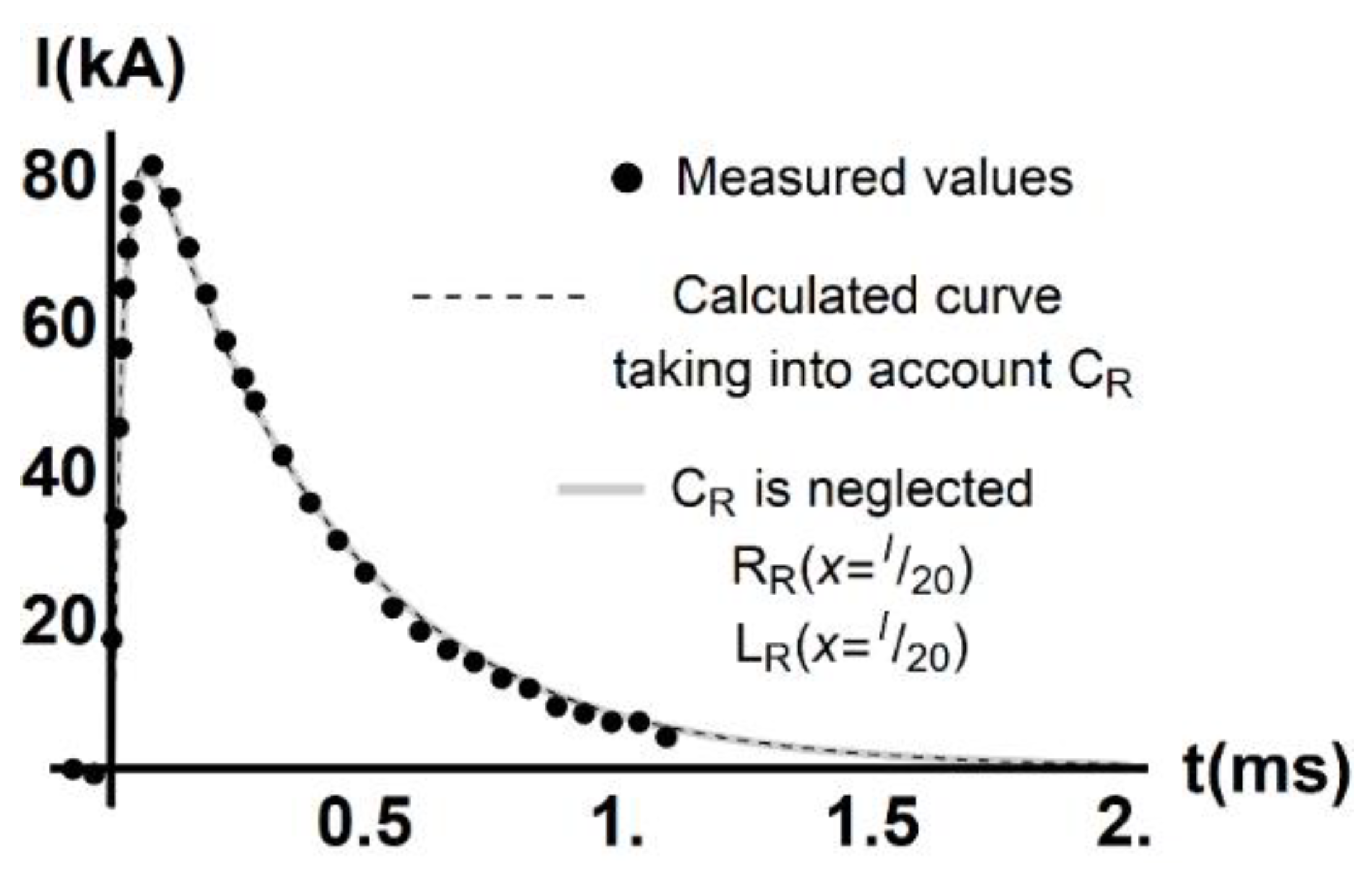
Correctness of the above parameters was verified by the comparison between the measured and calculated time dependencies of current i ( t ) when the rails were short-circuited at their beginning (x = 0). The voltage of the capacitor bank is 7 kV. The results are depicted in Figure 4.
As indicated by the solid line in Figure 4, our fitting shows that the dependence of resistance R R ( x ) and inductance L R ( x ) on position can be neglected. As can be seen in Table 2, the increase of quantity R R ( x ) with the position x is very weak (the corresponding coefficient being by three orders of magnitude lower than the constant parts). It is sufficient to approximate the value of R R ( x ) by a constant of value R R ( x = l 20 ) . The same conclusion holds for L R ( x ) . The linear term is very small compared to L 1 at the point of maximum acceleration, x l 20 (note that x ~ 0.02 m). Therefore, for the purpose of determining the current i ( t ) we replace L R ( x ) with a constant of value L R ( x = l / 20 ) . The error of the resulting current i ( t ) does not exceed 1.2% at any time. The analytical function i ( t ) is used as a boundary condition of our FEM simulation to describe the current at the terminals of the rails at any point in time.

3.2. Magnetic Field in System Rails–Projectile

Magnetic field in the system is described in terms of magnetic vector potential A following a Maxwell relation:
curl ( 1 μ curl A ) + γ ( A t v × curl A ) = J ext ,
where μ is the permeability, γ is the electric conductivity, v denotes the vector of the projectile velocity, and J ext is the vector of the current density driven by the external source current. We neglected the term 2 A t 2 as the time dependence of the current (see Figure 4) corresponds to 2 kHz only. Equation (2) has to be solved in each time step of the FEM simulation.
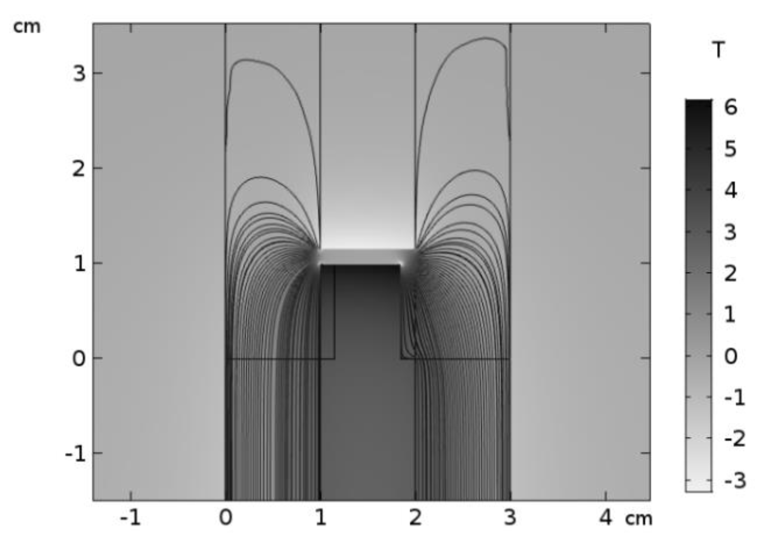
The boundary condition is of Dirichlet type; along a sufficiently distant boundary it may be written in the form A = 0. The non-uniform distribution of this current is accounted for using a finite element simulation (implemented in COMSOL Multiphysics [19]) as illustrated by Figure 5. The input current at the terminals of the device described by Equation (2) is i ( t ) shown in Figure 4 (gray curve), given as the solution of Equation (1). The knowledge of magnetic field (presented in Figure 5) then makes it possible to find the Lorentz force F acting on the projectile. Its value is given by the integral:
F = V ( J ext × B ) d V ,
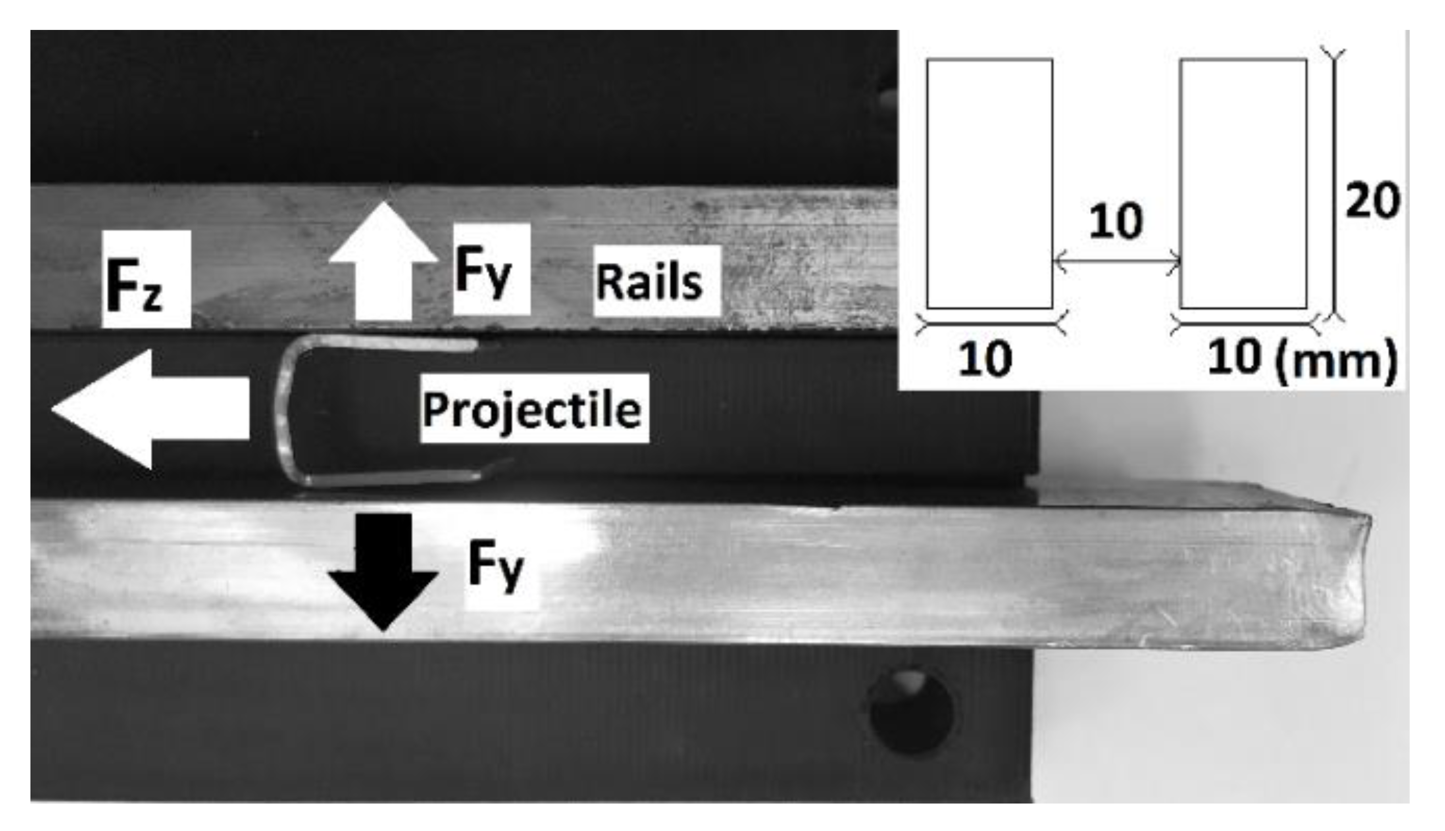
where B = curl A and integration is carried out over the volume of the projectile. The vector of F generally consists of two parts Fz and Fy, see Figure 6.
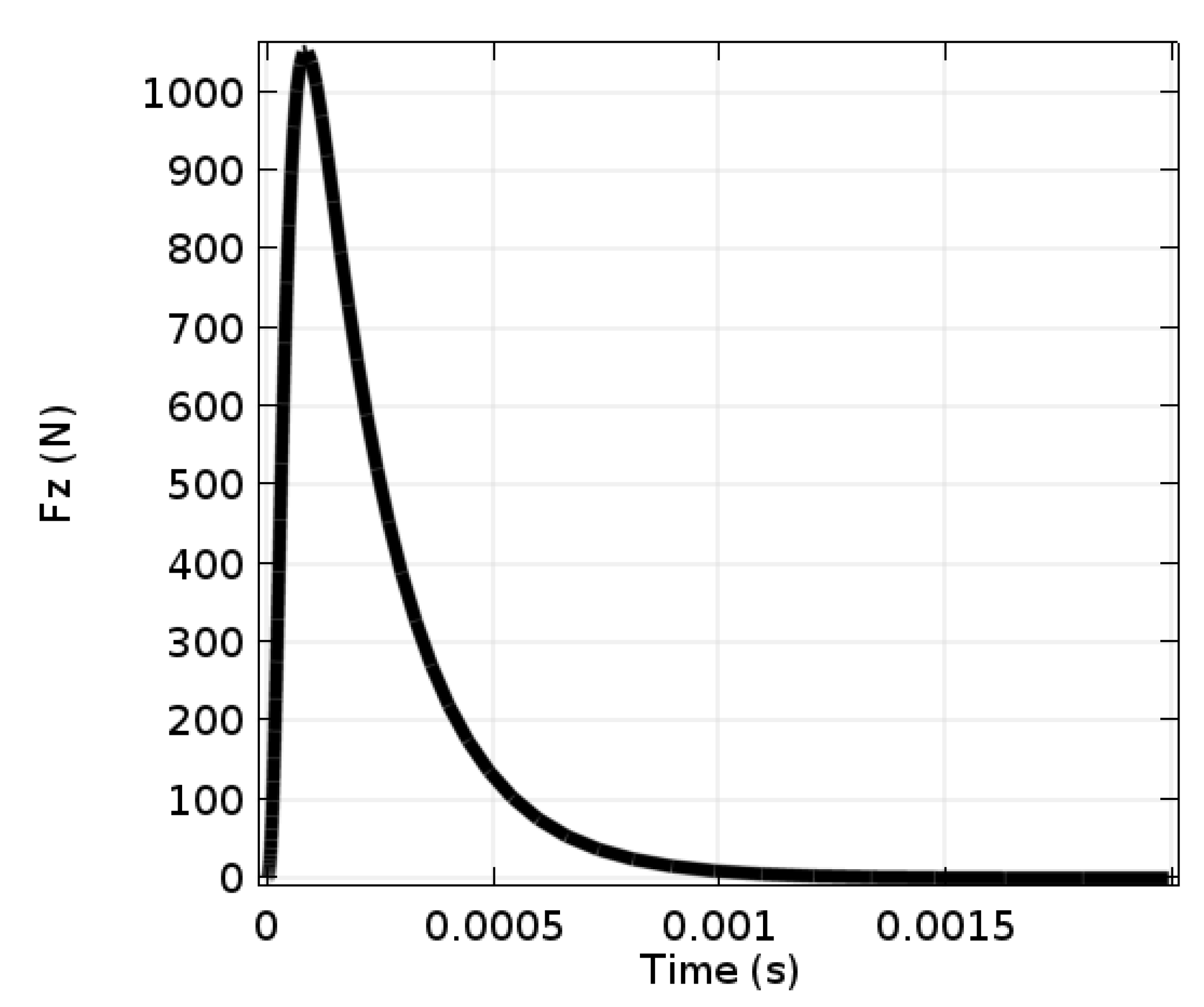
The force Fz produced by the current passing through the front of the projectile accelerates it in the z direction, while the current passing through both sides of the projectile produces the friction force Fy, in the y direction. The dependence of force Fz on time is shown in Figure 7. The peak value of the force Fz reaches about 1050 N.

3.3. Motion of the Projectile

The equation of motion can be written in the form:
m x = F z F f ,  
where m is the mass of the projectile, and Ff is the sum of drag forces (consisting generally of the friction force and the aerodynamic resistance). The initial conditions for this equation are x(0) = 0 and x(0) = 0, and the prime denotes the time-derivative.
The system of Equations (1)–(4) is strongly nonlinear and a numerical solution is required, e.g., FEM modelling has shown merit in describing rail guns in agreement with experiment as mentioned in the Introduction. An important complication is also represented by some parameters that cannot be determined exactly, such as the drag forces. We used the following additional simplifications: first, no part in the system rails–projectile is ferromagnetic. In such a case, Equation (2) may be rewritten in the form below taking into account the Coulomb condition div A = 0.
Second, the velocity ν of the projectile in the experiment is of the order of 10 m/s so the last term of Equation (2) is negligible compared to the first two terms. We obtain:
Δ A   μ γ A t = μ J ext .
These approximations facilitate a numerical solution of Equation (5), to obtain the magnetic field and the accelerating force for a current density Jext according to Equation (3). Note that the current density varies dramatically in the cross-section of the rails but is relatively homogenous in the projectile due to its small dimensions and it is a function of input from the capacitor bank, indeed. We used COMSOL Multiphysics [19] to simulate the device in three dimensions. It was established that the component Fz of the Lorentz force F acting on the projectile is produced mainly by the current passing through its front part, but a non-negligible contribution of it is also generated in its legs.
On the other hand, the current density Jext over its cross section is distributed non-uniformly (see Figure 5) because of the complicated geometry of the system and because of the skin effect generated by time changes of the magnetic field.
The drag force acting on the projectile by rails is given by the component Fy of the Lorentz force multiplied by the corresponding coefficient and by the force of elastic origin caused by heating of the rails and projectile whose dimensions may expand. This downforce can only be estimated from a suitable experiment. The aerodynamic drag force is a function of the frontal area of the projectile and square of its velocity (via Mach number) [20].

4. Measurements

The measurements consisted of finding the field current and measurement of the time-dependent trajectory of the projectile.

4.1. Measurement of the Circuit Parameters and Field Current

The measurement of inductances was carried out by the four-point method, using apparatus MT 4080A (the frequency being 100 kHz). The inductance of the barrel was measured when it was short-circuited at the beginning and in the end. These two values were used for determining the dependence of inductance on the projectile position.
The time dependence of the field current was measured using an oscilloscope. The results are the black points in Figure 4 and their agreement with the modelled values is excellent.

4.2. Measurement of the Magnetic Force

The aim of this measurement was to find the force acting on the projectile during its acceleration. As any direct measurement of this force is practically impossible, we chose a procedure which consists of measuring the projectile trajectory as a function of time. Its derivative with respect to time then provides its velocity and another derivative is its acceleration, which, after multiplication by the mass of the system, gives the driving force.
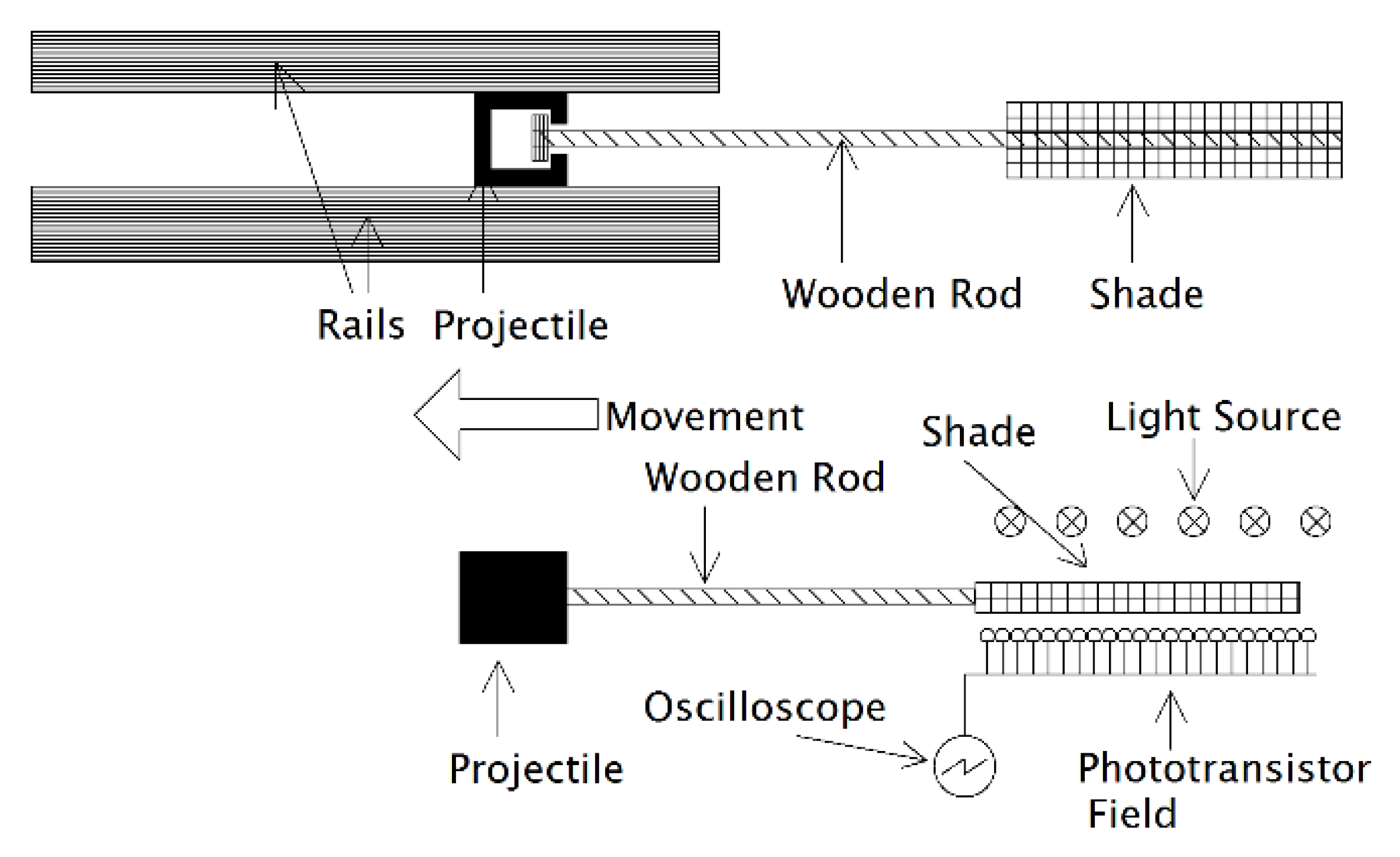
Preliminary experiments, using a high-speed camera, showed that the acceleration is produced only on a very short part of the trajectory (several cm), recorded the position of the projectile. For such short trajectories and corresponding times, the camera proved to be unusable because of an unacceptable distortion of the results. That is why we used a dense network of optical gates instead, consisting of phototransistors KPX89. The projectile was mechanically connected with a drawbar with shade (see Figure 8) and the whole system was carefully weighed. From above, the phototransistors were illuminated by LED diodes placed at a sufficient distance from them so as the luminous flux at the place of phototransistors was uniform.
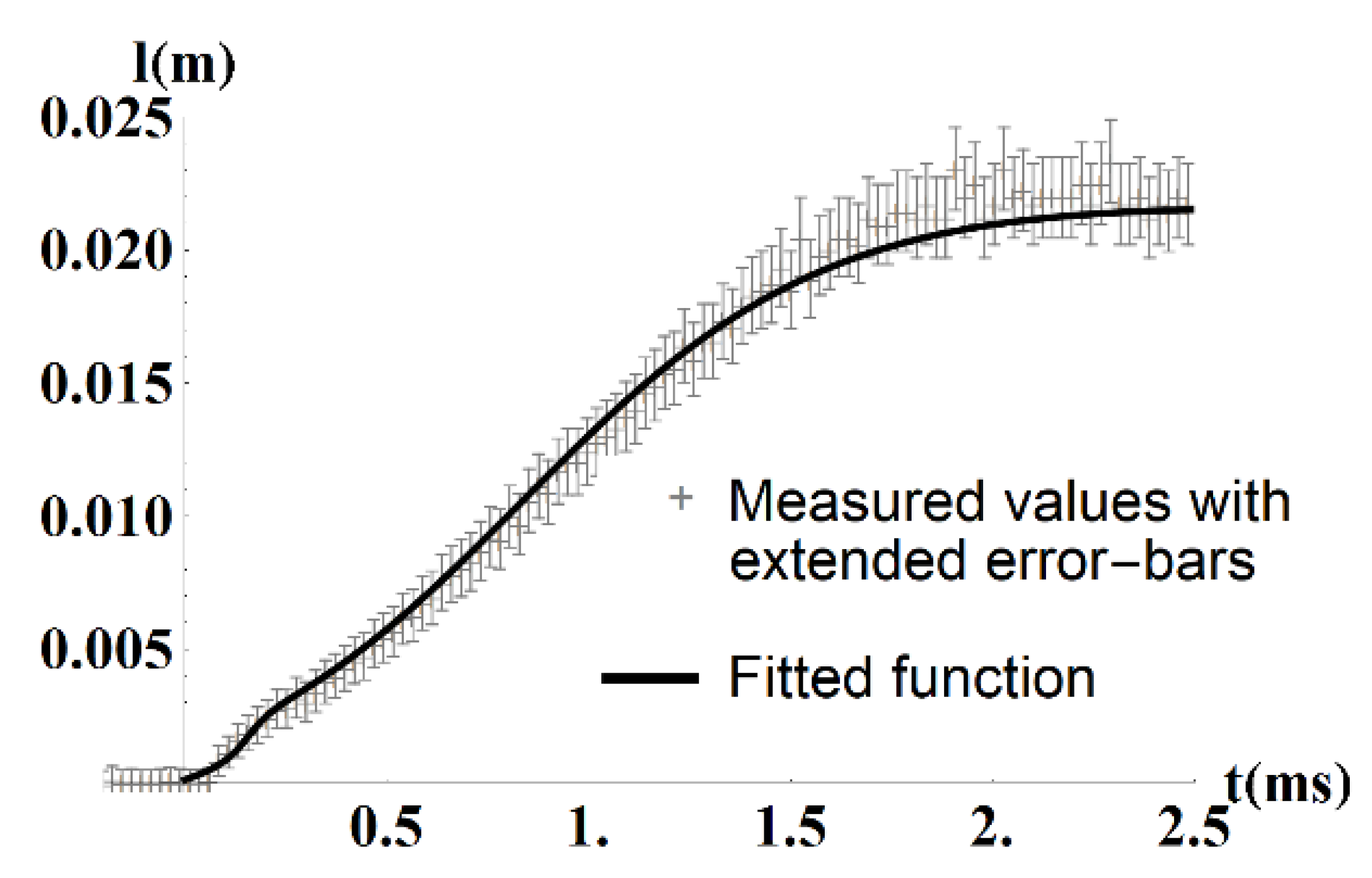
The position was recorded by the oscilloscope as a voltage on a voltage divider. The voltage was proportionally connected with a towed shade, so the trajectory was then determined from this voltage (the dependence of position on voltage was calibrated before and was strongly nonlinear). We also included uncertainties that could occur during the measurements. These were incorporated in the accuracy of recording the position and measurement of voltage (uncertainty of type B). The launch was repeated four times and it was observed that the peak of the force (determined by the initial curvature of position as a function of time) was always the same. For further analysis, we selected the launch, where the projectile sustained the least amount of plastic deformation during acceleration. As a result, the uncertainty of type A was neglected. The comparison of different uncertainties of type B showed that the error of oscilloscopic measurements is negligible with respect to the error of recording the position, and, therefore, it was not considered. The final uncertainty of type B was determined as 0.25 mm at time t = 0 and extended by coefficient 2. At t > 0 this uncertainty grows due to combination of signal from more phototransistors and nonlinear dependence of detected voltage on position. The resultant dependence of the position x on time (together with the corresponding error-bars) is depicted in Figure 9.
An analytical description of the trajectory was obtained by fitting a combination of two sigmoidal functions and one linear function shifted by a constant time t 0 = 0.05   ms to the discrete data from the measurement of trajectory. The fitted function is shown in Figure 9. The first sigmoid was intended for modelling the initial growth and the peaks of velocity and force. The second sigmoid describes the time evolution of trajectory after the first peak of velocity and force mainly in the interval (0.5 ms–2.0 ms).
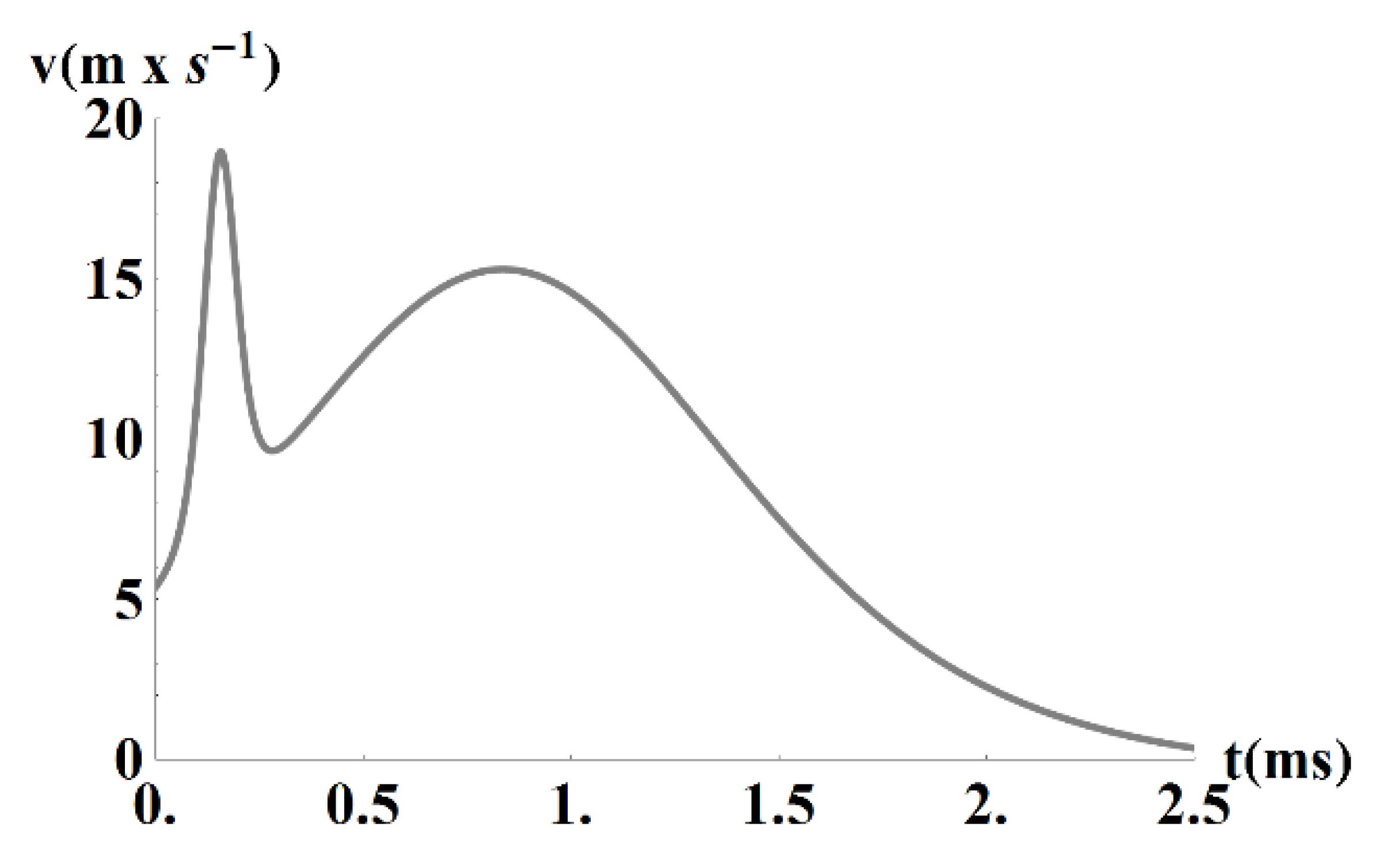
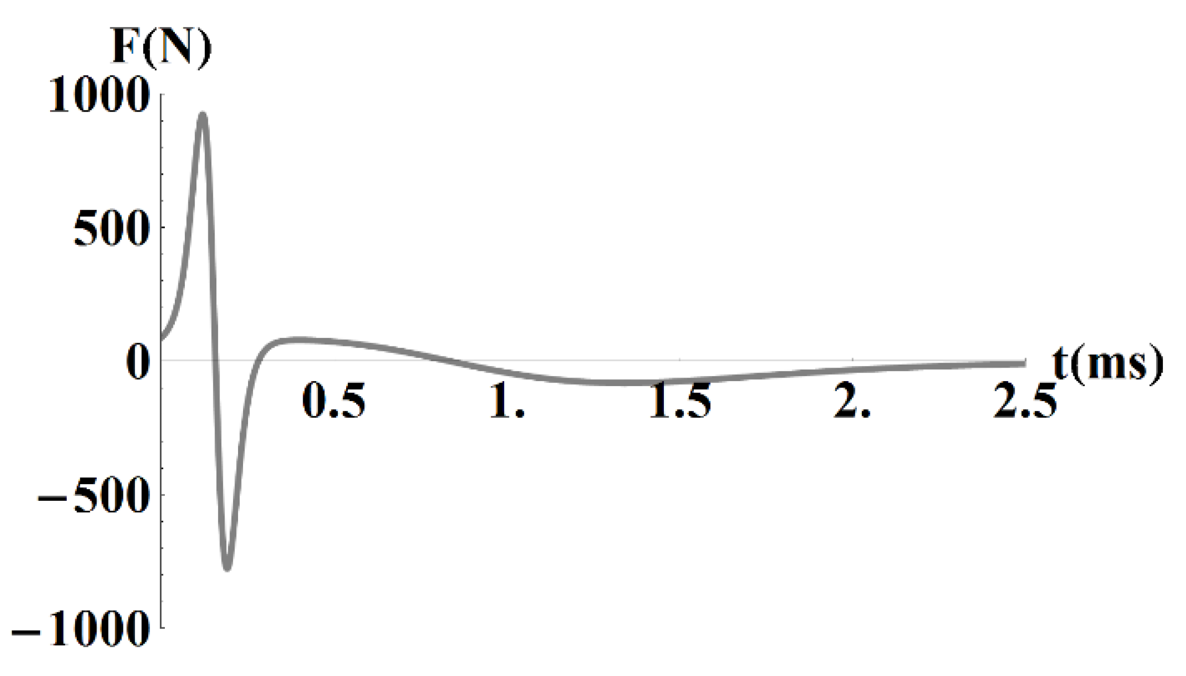
The velocity and acceleration trends of the projectile were obtained by taking time derivatives of the analytical expression for position. The force then follows from Equation (4). Their time dependencies are shown in Figure 10 and Figure 11.
We convinced ourselves that the above two sigmoidal functions, in combination with a linear function of time allow for a much better fit of the position as a function of time than higher order polynomial functions. A fit based on higher order polynomials introduces unphysical artefacts in the resulting force at higher times. This drawback outweighs the nonzero velocity and force at t = 0 , introduced by the use of smooth sigmoidal functions in combination with the measured abrupt increase of position at t = 0 (see Figure 9), caused by the finite reaction time in our position tracking device. Another uncertainty is most probably caused by the parasitic effects in electronics exposed to strong magnetic field generated at the beginning of the current pulse, despite capturing data in the optical manner. However, this behavior does not compromise our comparison of the measured and simulated forces at higher times.
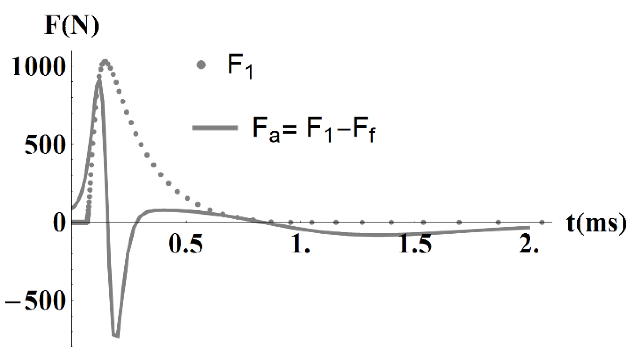
Figure 12 contains the time dependence of two forces: the simulated magnetic force (see Figure 7) and the force accelerating (decelerating) the projectile (in Figure 11) derived from our experiment. These forces were obtained for a projectile of mass 5.3 g that was measured before the shot. Their difference should provide the information about the total drag force causing deceleration of the projectile.
The simulated force was shifted in time so that the first maximum of its first derivative with respect to time would coincide with the same maximum of the measured force. This synchronization is based on an assumption that the time dependence of the drag force is much smaller than in case of the accelerating force at t 0.1   ms .
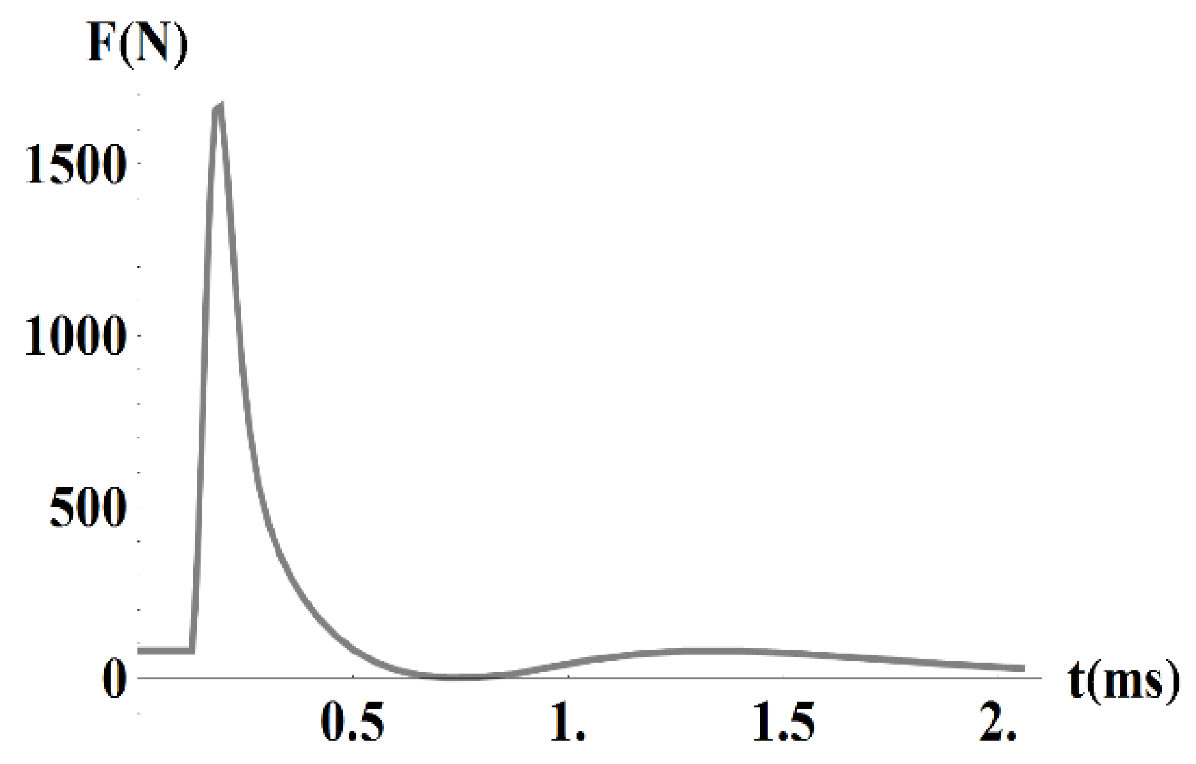
The trend of the friction force (the drag force after subtraction of the aerodynamic force and the static friction force) is depicted in Figure 13. It can be seen that the total friction force is positive as excepted. In a small interval around 0.7 ms the friction force approaches zero but remains positive. Its minimum value is particularly sensitive to inaccuracies both in modelling and experiments.
At times smaller than approximately 0.05 ms, our experimental and modelling methods do not provide reliable description of the friction force. However, it is reasonable to assume, that it is dominated by a constant initial friction force, as shown in Figure 13 at small times. The point of “unsticking” of the projectile from the initial position (point of sharp increase of force on Figure 13), coincides with the peak current. Then a sharp increase of the friction force follows, caused by the pressure between the projectile and rails (see force Fy in Figure 6). The time dependence of the friction force presented in Figure 13 is the main result of this work.

5. Conclusions

The article presents experimental data of a railgun and their interpretation based on a mathematical model. The first part of the model consists of the equivalent circuit, which represents the capacitor bank and rails with the moving projectile. The complete model is given by two ordinary differential equations describing the transient current in the equivalent circuit and motion of the projectile, and one partial differential equation describing the distribution of magnetic field necessary for finding the magnetic force.
The model was solved using several approximations. Mainly, we estimated the currents induced in electrically conductive parts due to motion of the projectile to be negligibly small compared to the current supplied by the capacitor bank, and also, we neglected the parasitic capacitance of the rails.
One of the most error prone tasks was the measurement of the position of the projectile in a short time interval after launching. Any noise in the position as a function of time brings about greater inaccuracies in the velocity, acceleration, and total accelerating (decelerating) force.
The simulated time dependence of force is broadly in agreement with the measured quantities. We are encouraged mainly by the good quantitative agreement of the maxima of the measured and simulated forces. We note that our study focused on lower velocities where the friction force has a significant impact on rail degradation. The only unintuitive feature is the almost vanishing value of the friction force in a short time interval around 0.7 ms. We note that it is extremely complicated to model the friction force directly as it is affected by many factors related to the parameters of the interface between the projectile and the rails which are hard to track even experimentally.
Our further research in the domain will be focused on improving the mechanical part of our model in order to provide even better time-dependent characteristics. Furthermore, efforts will be devoted to developing more accurate experimental methods.

6. Patents

The reported work resulted in a patent application filed with the Czech National Patent Office, number: PV 2019-524 (D19083379). The first search report is pending.

Author Contributions

Conceptualization, T.T., J.Z. and I.D.; Data curation, T.T.; Investigation, F.R.; Methodology, I.D.; Project administration, T.T.; Resources, V.P.; Supervision, L.D. and I.D.; Validation, L.D.; Visualization, F.R.; Writing—original draft, T.T.; Writing—review and editing, J.Z. and I.D. All authors have read and agreed to the published version of the manuscript.

Funding

This research received no external funding. T.T. received internal funding from a doctoral student funding scheme provided the Faculty of Electrical engineering of CTU Prague, project number: SGS19/061/OHK3/1T/13.

Acknowledgments

This paper was realized thanks to support of Department of Electrotechnology on the Faculty of Electrical Engineering, Czech Technical University in Prague. We also acknowledge fruitful discussions with colleagues from University of Defense in Brno, and the contribution of the Czech ministry of Defense, that manages the experimental facility.

Conflicts of Interest

The authors declare no conflict of interest. The funders had no role in the design of the study; in the collection, analyses, or interpretation of data; in the writing of the manuscript, or in the decision to publish the results.

References

  1. McNab, I.R. Launch to space with an electromagnetic railgun. IEEE Trans. Magn. 2003, 39, 295–304. [Google Scholar] [CrossRef] [Green Version]
  2. Siaenen, T.; Schneider, M.; Hogan, J. Block diagram model for the simulation of an electromagnetic rail accelerator. In Proceedings of the 17th International Symposium on Electromagnetic Launch Technology, La Jolla, CA, USA, 7–11 July 2014; pp. 1–5. [Google Scholar]
  3. Uryukov, B.A.; Lebedev, A.D.; Milyaev, C.C. Influence of materials properties on the dynamics of metal armature acceleration in a railgun. In Proceedings of the Fourth European Symposium on Electromagnetic Launch Technology, Gelle, Germany, 2–6 May 1993; pp. 153–158. [Google Scholar]
  4. Zhang, Y.; Ruan, J.; Liao, J.; Hu, Y.; Liu, K. Nonlinear scaling study of a railgun. In Proceedings of the 16th International Symposium on Electromagnetic Launch Technology, Beijing, China, 15–19 May 2012. [Google Scholar] [CrossRef]
  5. Wang, Z.H.; Wan, M.; Li, X.J. Numerical modeling of electromagnetic railgun rail temperature field. Int. J. Appl. Electromagn. Mech. 2016, 51, 173–183. [Google Scholar] [CrossRef]
  6. Yin, D.; Xiao, H.; Li, B. Dynamics response of filament-wound composite barrel for rail gun with acceleration load. IEEE Trans. Plasma Sci. 2018, 46, 1847–1854. [Google Scholar] [CrossRef]
  7. Khandryga, D.V.; Plekhanov, A.V.; Tereschenko, A.N. Numerical simulation and experimental results of the metal armature acceleration. IEEE Trans. Magn. 1995, 31, 193–197. [Google Scholar] [CrossRef]
  8. Rodger, D.; Lai, H.C. A comparison of formulation for 3D finite element modelling of electromagnetic launchers. IEEE Trans. Magn. 2001, 37, 135–138. [Google Scholar] [CrossRef]
  9. Hundertmark, S. Comparing a Dynamic railgun simulation with experiment. J. Electr. Eng. 2011, 11, 4. [Google Scholar]
  10. Hundertmark, S.; Roch, M. Transient 3-d simulation of an experimental railgun using finite element methods. In Proceedings of the 16th International Symposium on Electromagnetic Launch Technology, Beijing, China, 15–19 May 2012. [Google Scholar] [CrossRef]
  11. Bayati, M.S.; Keshtkar, A.; Gharib, L. Numerical analyzing the electromagnetic launcher using FEM-3D in time domain. In Proceedings of the 16th International Symposium on Electromagnetic Launch Technology, Beijing, China, 15–19 May 2012. [Google Scholar] [CrossRef]
  12. Zhang, Q.; Li, J.; Li, S.; Liu, P.; Cao, R.; Cheng, L.; Yuan, W. Simulation and test study on different structure bore of electromagnetic launch. In Proceedings of the 17th International Symposium on Electromagnetic Launch Technology, San Diego, CA, USA, 7–11 July 2014. [Google Scholar] [CrossRef]
  13. Tumonis, L.; Kačianauskas, R.; Kačeniauskas, A. Evaluation of friction due to deformed behaviour of rail in the electromagnetic railgun: Numerical investigation. Mechanika 2007, 63, 58–63. Available online: https://mechanika.ktu.lt/index.php/Mech/article/view/14786 (accessed on 22 October 2020).
  14. An, S.; Lee, B.; Bae, Y.; Lee, Y.H.; Kim, S.H. Numerical analysis of the transient inductance gradient of electromagnetic launcher using 2-D and 3-D finite-element methods. IEEE Trans. Plasma Sci. 2017, 45, 1635–1638. [Google Scholar] [CrossRef]
  15. Go, B.S.; Le, D.V.; Song, M.G.; Park, M.; Yu, I.K. Design and electromagnetic analysis of an induction-type coilgun system with a pulse power module. IEEE Trans. Plasma Sci. 2019, 47, 971–976. [Google Scholar] [CrossRef]
  16. Meger, R.A.; Huhman, B.; Neri, J.; Brintlinger, T.; Jones, H.; Michopoulos, J.; Cairns, R.; Douglas, S. Electromagnetic railgun barrel damage experiments. NRL Rev. 2012, 85–92. Available online: https://www.nrl.navy.mil/content_images/2012Review/12_FA2.pdf (accessed on 22 October 2020).
  17. Marshall, A. Railgun overview. In Proceedings of the Impact Fusion Workshop, Los Alamos, NM, USA, 10–13 July 1979. [Google Scholar]
  18. Taher, S.A.; Jafari, M.; Pakdel, M. A new approach for modeling electromagnetic railguns. IEEE Trans. Plasma Sci. 2015, 43, 1733–1741. [Google Scholar] [CrossRef]
  19. COMSOL Multiphysics® version 5.3a. Available online: www.comsol.com (accessed on 22 October 2020).
  20. NATO—STANAG 4367, Thermodynamic interior ballistic model with global parameters, 2012–05. Available online: https://standards.globalspec.com/std/1686991/STANAG%204367 (accessed on 22 October 2020).
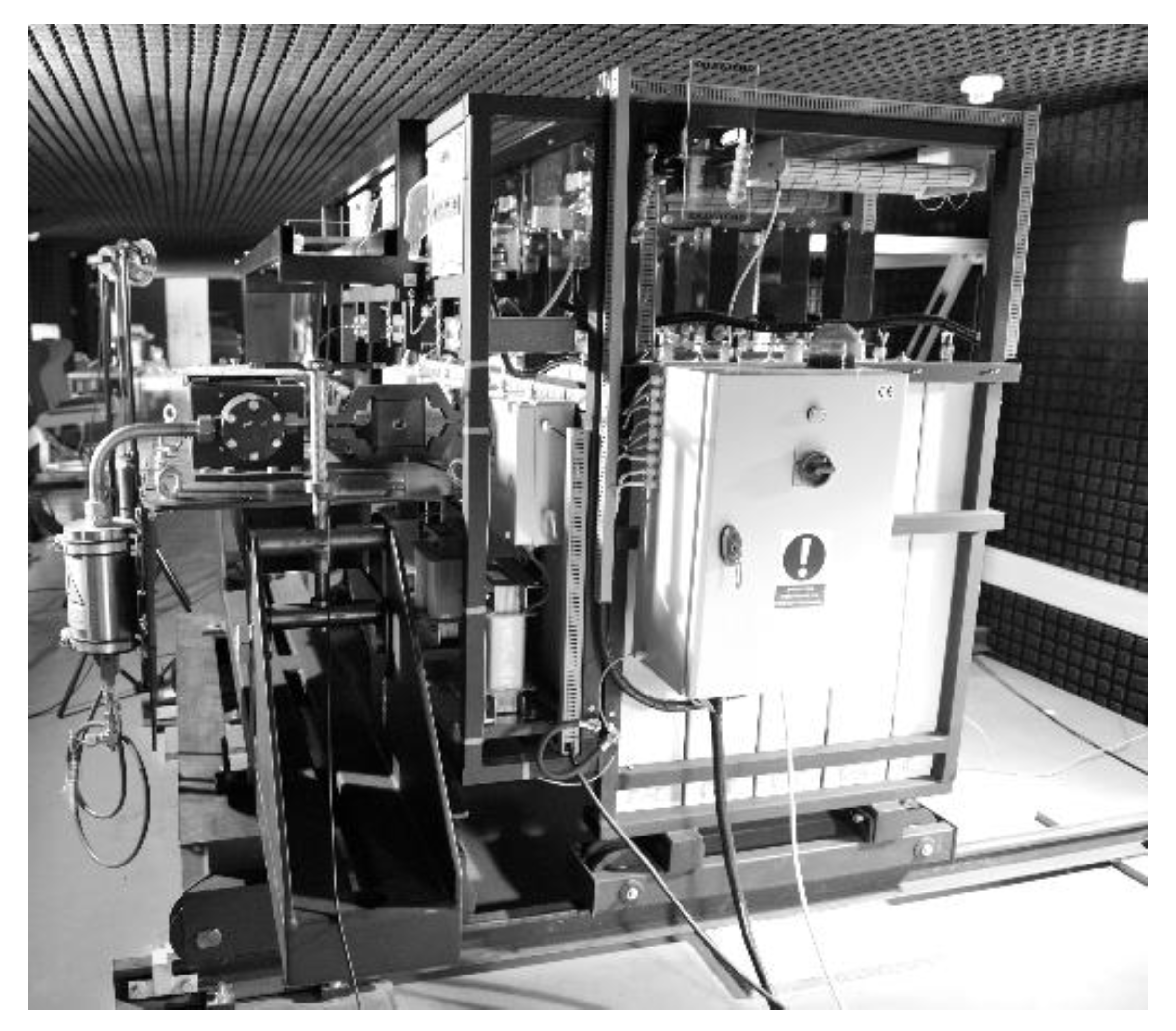
Figure 1. Experimental device including the capacitor bank.
Physics 02 00034 g001
Figure 2. Arrangement of the system.
Physics 02 00034 g002
Figure 3. Equivalent circuit of the system.
Physics 02 00034 g003
Figure 4. Time evolution of field current i ( t ) .
Physics 02 00034 g004
Figure 5. Rails and projectile with streamlines of the current at the time of its maximum magnitude, and component of magnetic field B perpendicular to the plain of the plot.
Physics 02 00034 g005
Figure 6. Rails and projectile with indicated magnetic forces (the cross section through rails is in top right corner).
Physics 02 00034 g006
Figure 7. Time dependence of force F z .
Physics 02 00034 g007
Figure 8. Measurement of trajectory: top view and side view.
Physics 02 00034 g008
Figure 9. Measured time dependence of trajectory.
Physics 02 00034 g009
Figure 10. Time dependence of velocity obtained from numerical derivative of trajectory in Figure 9.
Physics 02 00034 g010
Figure 11. Time dependence of accelerating (decelerating) force acting on the projectile.
Physics 02 00034 g011
Figure 12. Comparison of forces.
Physics 02 00034 g012
Figure 13. Time dependence of friction force.
Physics 02 00034 g013
Table 1. Meaning of particular elements in equivalent circuit in Figure 3.
L 1 Inductance of capacitor bank, circuit conductors and resistors
L R Inductance of rails
R 1 Resistance of conductors in capacitor bank and feeding cables
R R Resistance of barrel and projectile
U c Voltage of capacitor bank
Table 2. Values of parameters of the equivalent circuit (without C R that can be neglected).
ElementValue (Unit)
C 1 5.18 × 10⁻³ (F)
R 1 0.069 (Ω)
L 1 1.525 × 10⁻⁶ (H)
L R ( x ) 0.053 × 10⁻⁶ + 0.344 × 10⁻⁶x (H)
R R ( x ) 7.512 × 10⁻³ + 182 × 10−6x (Ω)
Publisher’s Note: MDPI stays neutral with regard to jurisdictional claims in published maps and institutional affiliations.