1. Introduction
Charged particle traps are important tools for studying the basic properties of atomic systems. Paul and Penning traps, and combinations thereof, can confine small numbers of particles over long timescales, by producing a potential energy minimum in which particles are stably confined [
1,
2]. With increasing trapped particle density, space charge can degrade confinement by decreasing the effective potential well depth. The present study explores whether it is possible to improve on the space charge limit in a Paul trap-type device by neutralizing the charge—that is, by loading the trap with quasi-neutral plasma instead of single or multiple species of the same charge [
3,
4]. Single species trapping is a well-established and thoroughly investigated topic; the trapping of plasma has rarely been considered, and most considerations were for specific applications such as antimatter storage [
5,
6]. New methods of trapping plasma for laboratory study, especially in the presence of radio-frequency (RF) fields and electrodes, are of ongoing interest in the field of low temperature plasma physics [
7].
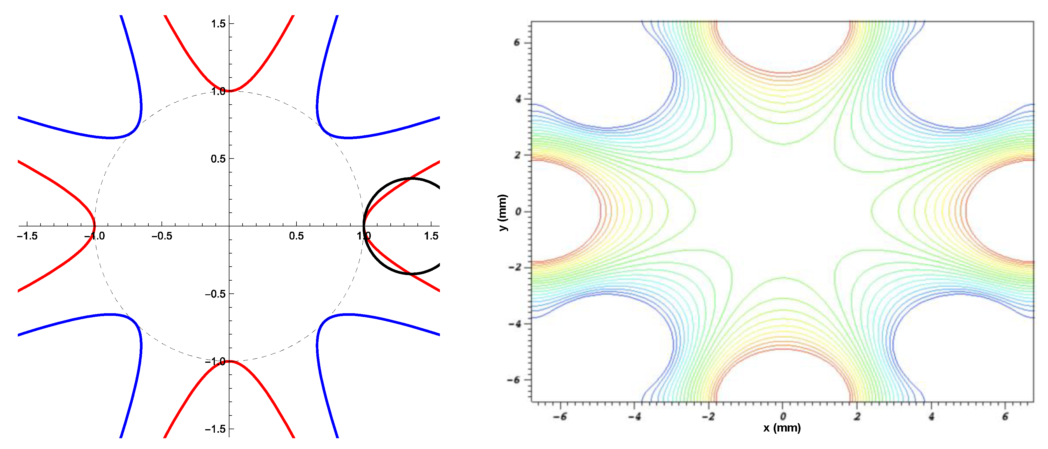
Charged particles cannot be trapped in three spatial dimensions (3D) by a static electric field (Earnshaw’s theorem). However, in a device with a spatially inhomogeneous external electric field that also varies in time, particles can experience a net restoring force toward the center. To achieve this, the equipotential surfaces generally should have a 3D saddle point at the center, and the time variation repeatedly flips the polarity of the saddle. Charged particles experience alternating focusing and defocusing forces with time. Because the focusing phase results in the particle moving closer to the center of the trap, where the field is weaker, the subsequent defocusing phase is relatively weaker, and the net effect is to restore the particle to the center. This is the principle of “strong focusing”, used also in particle accelerators and quadrupole mass spectroscopy. A quadrupole electrode geometry is often chosen, because it is well-described analytically and has simple periodic particle orbits; however, higher order multipoles—a subject of this study, see
Figure 1—stably trap particles as well, and have the advantage of a larger “field-free” region.
For particles to be stably trapped by a quadrupole field, the trap voltage and driving frequency must be chosen corresponding to the condition on the stability parameter:
where
q/
m is the particle charge-to-mass ratio, and the other parameters characterize the applied electric field,
is the voltage applied to the electrodes,
r0 is the quadrupole aperture radius, and Ω is the field oscillation frequency.) An approximate transverse (radial) potential well depth for a 2D quadrupole is given by
D = 1/4
Q V0 (note that this leads to a strong dependence on
V0) [
8]. The RF quadrupole strongly focuses particles within a range of charge-to-mass ratios, irrespective of sign.
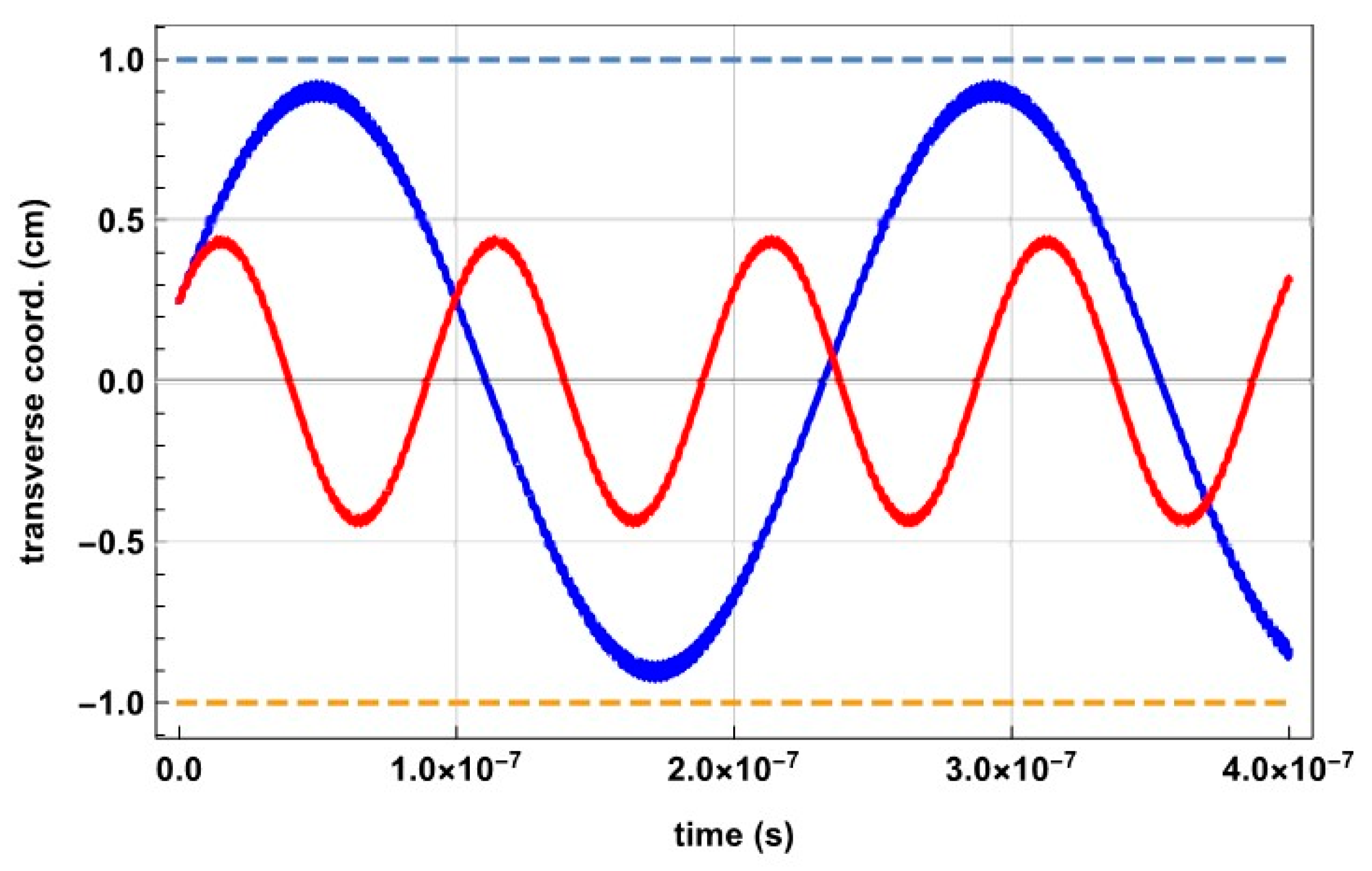
Figure 2 shows that two particles with equal mass but opposite charge (as in a pair plasma), and with the same initial position and velocity, are both stably trapped transverse to the quadrupole axis. The difference in trajectory arises due to the opposite direction of force initially experienced by the particles. Two distinct frequencies of oscillation are observed: high frequency RF jitter, superimposed on low frequency “secular” oscillation due to harmonic motion in the effective potential well of the trap. If the particles’ charge-to-mass ratio differs, both particles may still have stable trajectories (
Q < 0.9).
Figure 2 shows trajectories of particles with a charge-to-mass disparity of a factor of 10. With an equal charge magnitude, the light particle is more strongly focused, resulting in higher frequency secular motion, whereas the heavy particle experiences a shallower effective potential well and slower secular oscillation.
Higher-order multipole traps are not characterized by the single, constant stability parameter
Q, but rather by an adiabaticity parameter that depends on the location (radial position
r) within the trap:
where
N is the multipole order, and the inequality has been determined empirically [
10]. If a particle traverses regions of the trap for which
η > 0.3, it may gain kinetic energy; if sufficient energy is gained, it will subsequently be lost. This energy gain may in fact be useful in the context of collisionless RF heating [
11,
12], but is generally to be avoided in charged particle traps.
As the trapped particle density increases, space charge repels particles from the trap center, limiting the attainable trapped density and total trapped particle count.
Figure 3 shows that the effect of increasing space charge repulsion is to decrease the effective potential well, causing higher amplitude harmonic oscillation at a reduced secular frequency. With a continuing buildup of space charge, this effect will cause the particle to cross the trap boundary and be lost from the system. Consideration could be given to neutralizing this space charge [
13,
14]; for example, a positive ion distribution could be neutralized by adding electrons. But if the trap is stable for the relatively heavy ions (e.g., in the case of a quadrupole: 0.1 <
Qi < 0.9), the electrons will be unstable (
Qe > 100) and will be promptly ejected from the trap. If, on the other hand, the trap is designed to be stable for electrons, then ions will have
Qi ≈ 0—they are too massive to respond on the timescale of the trapping field, and they will be neither stabilized nor destabilized by the trap (see
Figure 2).
If the electrons are stably trapped, the positive ions will themselves be confined by the trapped negative space charge. If a trap is loaded with quasi-neutral ion-electron plasma of finite temperature, it is expected that the light species will initially expand faster than the heavy species, and ambipolar diffusion will then occur. The potential in the bulk plasma takes on the sign of the heavy species. The influence of the trap, though, is to restore the light species to the center; when this occurs, the density of the light species will now exceed that of the heavy species in the bulk plasma and a potential well will form. The heavy species becomes trapped by this well. The light species sees the effective trapping potential plus the space charge potential; the heavy species sees only the space charge potential, since its relatively large inertia reduces its effective trapping potential to close to zero.
2. Simulation Methods and Results
To test the hypothesis presented above for quasi-neutral plasma trapping, electrostatic particle-in-cell (PIC) simulation using the VSim 7.2 code from Tech-X Corporation (Boulder, Colorado, USA). [
15] has been performed. In the first case, a linear RF multipole with
V0 = 5.0 kV,
f = 100 MHz,
r0 = 0.5 cm is simulated in 2D, with a time step = 0.5 ns (or 1/20 the RF period), 100 particles per cell, and 250 cells spanning each transverse dimension. The essential points can be investigated in 2D, which makes simulations quick to run for testing various parameters and reduces needed computing resources. The criterion of setting the simulation time step equal to 1/20 of the RF period was used for all of the simulation runs (no significant changes to simulation outcomes were observed by using a finer time step). Following the usual electrostatic PIC framework [
16]: charge density is calculated by depositing macroparticle charge on a discrete grid; the electric potential and field are calculated from Poisson’s equation; a leapfrog particle mover is used to update particle positions and velocities. Collisions are not explicitly included in these simulation runs (see Discussion for future work).
In order to resolve the light species motion without having lengthy simulation runs to capture the heavy species motion, a mass disparity for the simulated plasma of
m−/
m+ = 1/10 is chosen (specifically, the negative particles have electron charge and proton mass, and the positive particles have proton charge and 10-times proton mass). This is sufficient to preserve the essential quality that would apply to an ion-electron plasma, i.e., that the heavy species is negligibly focused compared to the light species. A multipole of order
N = 8 (16 electrode poles) is chosen in order to demonstrate the feasibility of this type of configuration, with the imparted benefit of a larger trap-field-free volume due to the steeper trap potential well, with increasing multipole order.
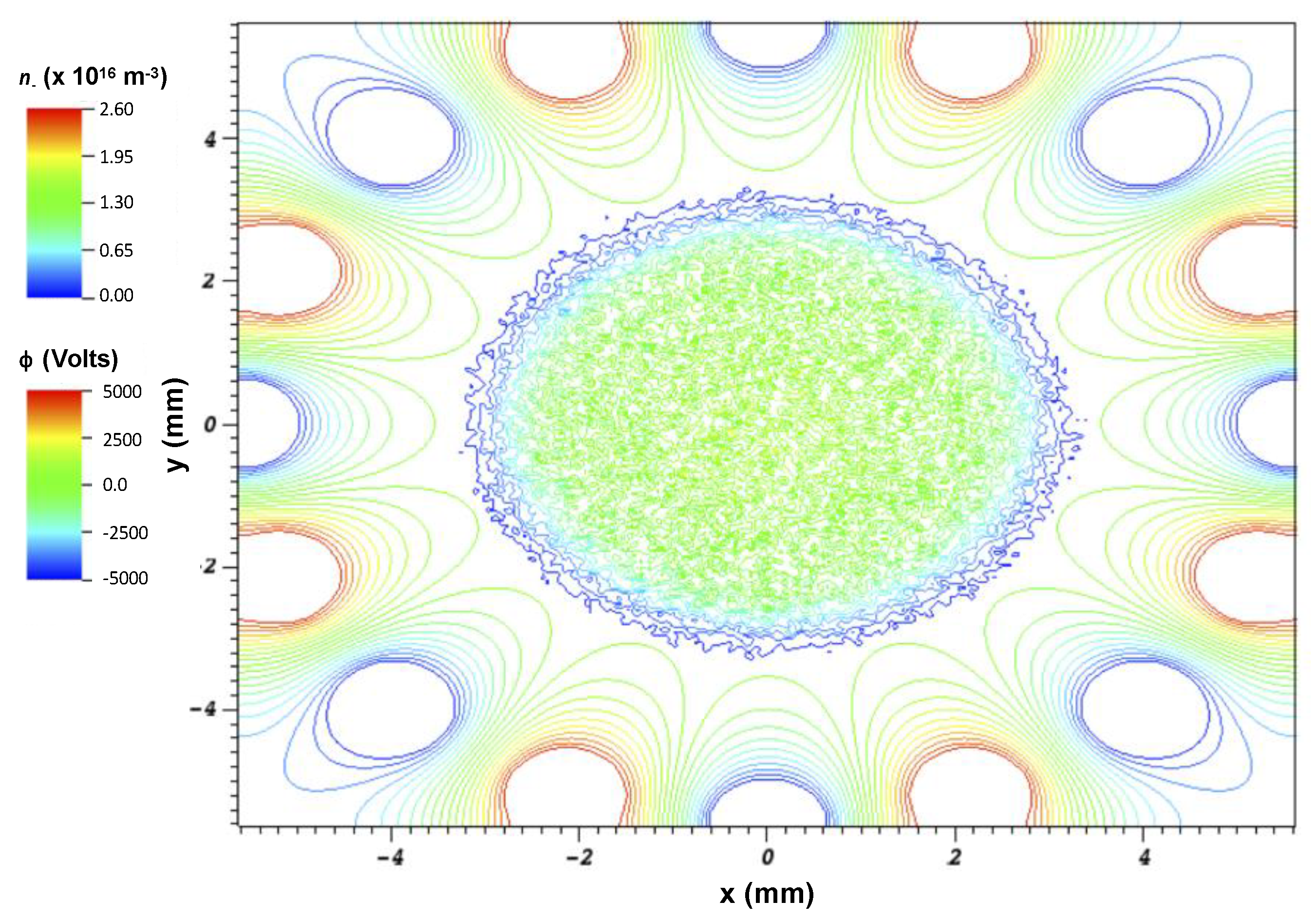
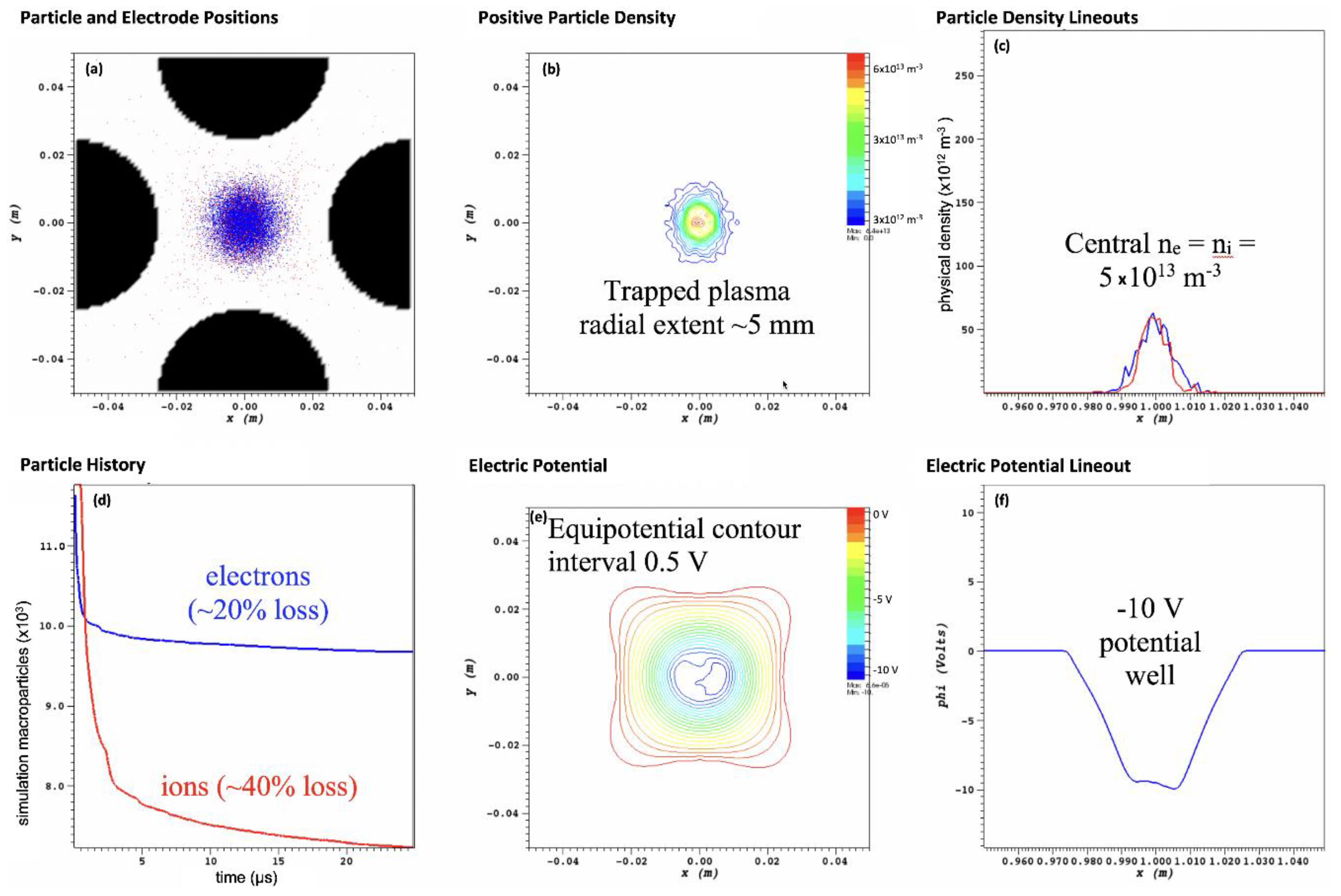
Figure 4 shows an example of simulation results from this configuration, confirming the ability of the multipole field to stably trap the quasi-neutral plasma of disparate mass. For comparison, with the same configuration but zero RF voltage, the plasma was quickly lost from the trap by ambipolar diffusion (over 50% particle loss by 1.2 μs).
In the second simulation case,
N = 8 at
f = 100 MHz is still employed, but with five times the aperture radius (
r0 = 2.5 cm) (this would correspond to two orders of magnitude greater trap volume in a 3D case in which volume ~
r03). To partially compensate for the larger radius, trap voltage is increased (
V0 = 10.0 kV).
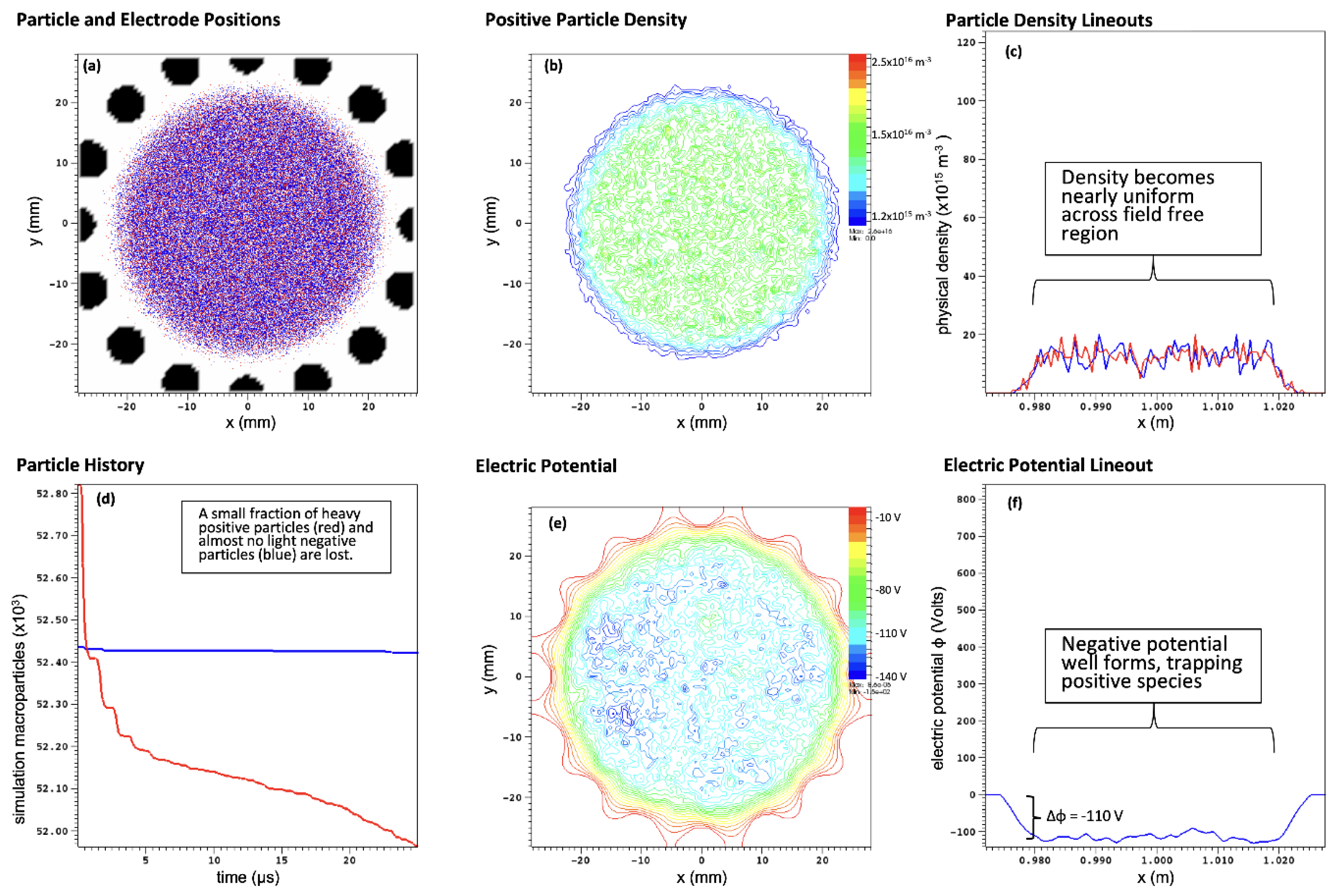
Figure 5 shows details of this simulation. An initial Gaussian spatial profile (half-width 5.0 mm) for each species is loaded with peak density
n = 1.0 × 10
17 m
−3 and temperature 1.0 eV. The light particle species experiences almost no losses during the run (25 μs, 2500 RF periods). The heavy species is negligibly affected by the trapping RF, and the faster heavy particles in the initial distribution are lost within the first 5 μs. Additional heavy particle loss occurs until the excess of light, the negative charge that develops leads to a negative potential well, and this well (~100 V depth) electrostatically traps the remaining heavy, positive particles, and less than 5% of the heavy particles are lost over the course of the simulation. The density profile flattens, with nearly uniform density
n = 1.5 × 10
17 m
−3 occupying the field-free volume of the trap, and a sharp edge near the trap boundary (
r = 2.0 cm).
To consider the effect of the full ion–electron mass disparity, a hydrogen plasma in an RF quadrupole is simulated (see
Figure 6). The RF voltage is 1.0 kV, and the frequency is 250 MHz, with an aperture radius of 2.5 cm, such that the quadrupole stability parameter of the electrons is
Qe = 0.45 (strongly trapped) while that of the protons is
Qp = 2.0 × 10
−4 (negligibly trapped, but stable). The figure shows the simulation state after many RF periods (
t = 6200 τ
RF), and the time shown is during the zero-crossing of the RF (so that the electric potential shown is just due to the plasma). The initial particle distribution loaded in the trap was Gaussian, with peak density 2.5 × 10
14 m
−3, and temperature 1.0 eV. The particle count history vs. time shows that some electrons (~20%) in this distribution have initial energies greater than the pseudopotential well depth of the trap; these are promptly lost (Δ
t ~ 1 μs), leaving an excess of positive charge. This positive space charge that develops in turn causes electrons to be refocused to the trap center, and a fraction of the protons (~40%) to be expelled (Δ
t ~ 1 μs). After this initial equilibration, protons continue to be lost at a slower and decreasing rate, increasing the negative space charge in the trap. This continues until a negative potential well forms (approximately −10 V) of sufficient depth to prevent further significant proton loss. The initial loss of electrons, leading to a positive space charge, drives the loss of ions in this simulation case. A smaller value of
Qe could reduce this prompt expulsion of electrons, or, alternatively, a higher order multipole could prevent the RF field from strongly perturbing the initial distribution; the latter approach is explored in the next case.
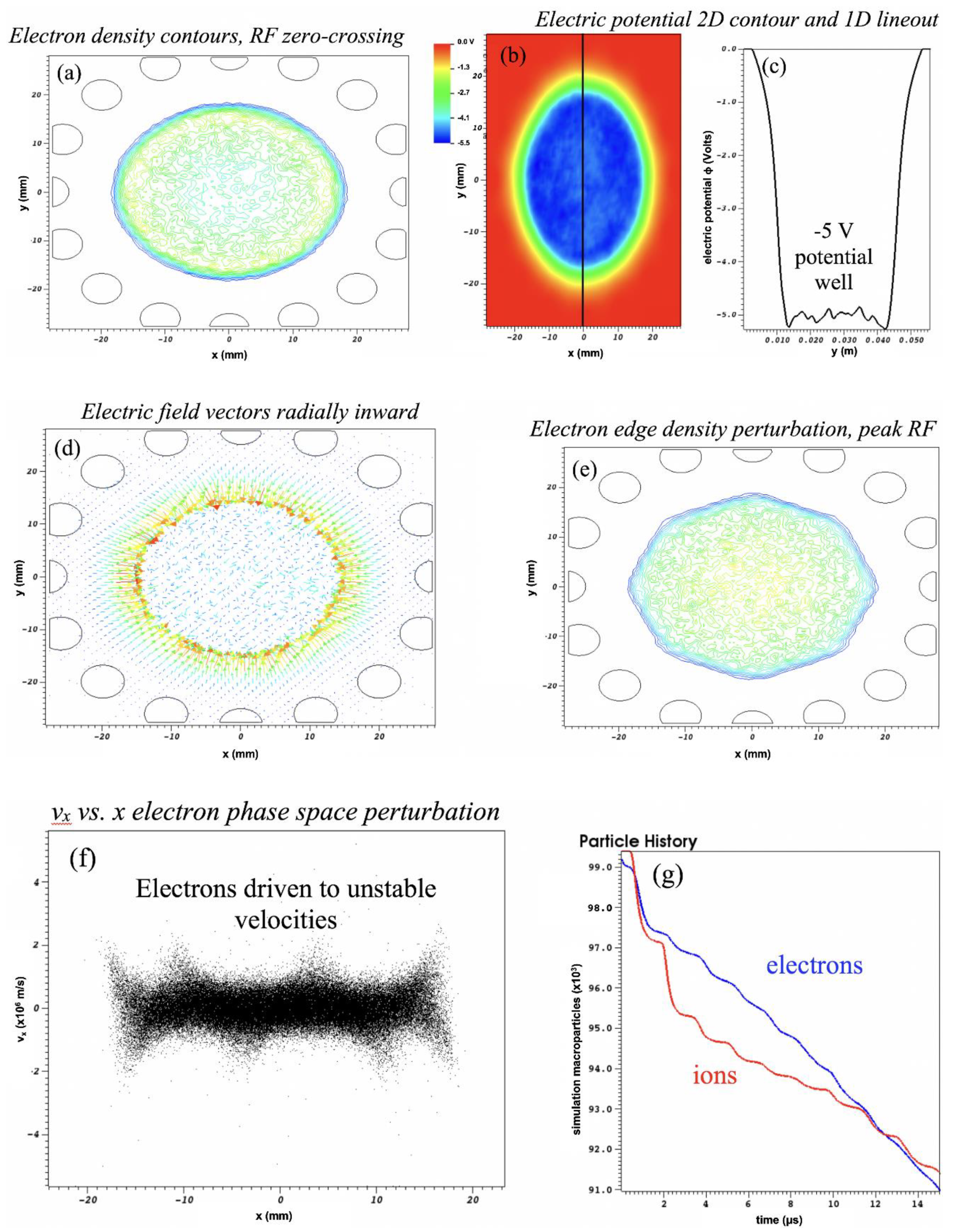
Figure 7 shows a simulation of a hydrogen plasma in a 2D hexadecapole (
N = 8), with the same initial plasma and RF characteristics as in
Figure 6 (except now f = 500 MHz). Higher order multipoles have larger regions that are nearly field free at trap center, and, correspondingly, the pseudopotential well is not parabolic as in the quadrupole case but has much steeper edges. The result is a sharp boundary to the trapped plasma distribution, as shown in the density contour plot
Figure 7a, and a steep edge gradient and central plateau in electric potential φ, as shown in the electric potential contour plot
Figure 7b and lineout
Figure 7c. As compared to a case without trapping RF, in which ambipolar diffusion would show a prevailing electric field radially outward,
Figure 7d shows a field free region at center of the trapped plasma region, and a strong radially inward field pointing from a halo of positive ions toward the excess of trapped electrons in the trap volume. The strong trapping field at the edge drives significant perturbation of the plasma spatial distribution, as shown in
Figure 7e, where the
N = 8 perturbation is clearly observed (RF is at peak value here). This perturbation also manifests in the plasma velocity distribution, as shown in the electron phase space plot of
x-velocity vs.
x-position in
Figure 7f. The
N = 8 signature is observed, and some electrons are driven to unstable trajectories and subsequently lost. These electrons are lost from the trap at a nearly constant rate from
t = 5 to 15 μs (see
Figure 7g), and the electron loss rate exceeds the proton loss rate, meaning that the negative potential well will deteriorate as time advances further and the plasma trapping will degrade correspondingly. Indeed, an oscillation of the central potential vs. time is often observed in this type of simulation run, with the average well depth decreasing. However, if this 2D case is extrapolated to a 3D, spherical distribution, the loss current associated with the outward electron flux is only ~10 μA—this means that the electron loss could be replenished or even reversed in an experimental situation by a modest influx from an electron source.
3. Discussion
The concept exploration study presented here with 2D PIC simulation results has illustrated the possibility of trapping plasma of various compositions (light ion-heavy ion and ion–electron) and at various multipole orders (quadrupole to hexadecapole). A broad range of practicable plasma trapping scenarios exists, and laboratory experiments to test the concept of trapping plasma with RF multipole fields, both with and without background magnetic field, are in preparation [
17]. The choice of experimental parameters may be guided by further simulation studies, both in 2D and 3D, which can explore in depth the effect on plasma trapping of multipole order, frequency, voltage, aperture radius, and, in particular, 3D geometry. The necessity of remaining in the adiabatic regime as the multipole order increases is to be scrutinized, as the collisionless RF heating effect associated with non-adiabatic trajectories at the trap boundary could be balanced by thermalization of these energetic particles when they return to the bulk plasma. Electron losses in the results presented here are caused by the deep penetration of the trapping field into the bulk plasma (quadrupole case) or a strong edge field causing energy gain of particles near the trap boundary (hexadecapole case). Both loss scenarios may be ameliorated through judicious choice of trap loading schemes (e.g., introduce quadrupole particles continuously so that the entire RF cycle is sampled) and by adjusting parameters in the hexadecapole case, such that the adiabaticity condition
η < 0.3 is maintained throughout the trap volume sampled by plasma particles. The effect of Coulomb collisions will be studied in future work, with plasma conditions of greater collisionality and longer simulation duration, since it is to be expected that some fraction of collisions between unlike species will destabilize particle trajectories. Fine spatial resolution, with respect to the Debye length, will be employed to capture long-range effects via deposition of charge on the PIC grid, and a collisions framework within VSim will be explored for elastic binary Coulomb collisions, as well. Additional simulations may also explore in detail the addition of axial or cusp external magnetic fields, with field strength varying such that conditions above, at, and below ponderomotive gyroresonance [
18] are investigated. Furthermore, the transition to higher plasma density is to be studied, such that the driving frequency and plasma frequency become comparable,
fRF–
fp. In the latter case, especially with a low multipole order, as in the quadrupole, a large field enhancement due to plasma response is possible, and plasma may be depleted, as in the formation of caviton structures [
19]. The formation of RF plasma sheaths in case of high density at the trap boundary may be observed, and the skin depth of the plasma (with and without magnetized electron species) will play a determining role in trapping field penetration in the high-density case.
