1. Introduction
The petroleum industry remains one of the major energy providers as well as the supplier of products to petro-chemical industries. It represents a critical infrastructure that at the same time needs to manage the risks of potential major accidents from handling hazardous materials. Norway is one of the larger oil and gas producers, with a high number of subsea production and processing facilities, topside platforms with seabed mounted or submersible structures, and floating production, storage, and offloading vessels located on the Norwegian Continental Shelf.
The control and safety of the operation are ensured by the on-board Operational Technology (OT) systems. The term “OT systems” is commonly defined with reference to Gartner Glossary as “hardware and software that detects or causes a change, through the direct monitoring and/or control of industrial equipment, assets, processes, and events” [
1].
In the past, OT systems used to be physically separated from the outside world and largely built upon proprietary technologies. In recent years, more off-the shelf information and communication (ICT) technologies have been integrated into OT systems to meet the demands for high connectivity and open platforms for data exchange. This demand for connectivity and data exchange go beyond the borders of the OT systems, as many applications that rely on data, such as systems for condition monitoring, plant optimization, and maintenance planning, are located in various information technology (IT) networks.
New ways of operating the facilities means that vital OT functions, such as control, are moved to remote operation centres. IT equipment is also increasingly used to safeguard OT functions. Examples are field instrument monitoring, maintenance, and configuration systems that have traditionally been seen as IT systems because they do not directly affect production.
This creates a need for more holistic solutions where OT systems must be able to operate without the negative influence by outside IT systems. This includes the management and monitoring of the multiple connection points to the company’s IT systems and their extensions via the internet to external networks and cloud solutions.
Parts of the OT systems are dedicated to ensure safety. This includes systems, such as emergency shutdown (ESD) systems, fire and gas (F&G) detection systems, and process shutdown (PSD) systems. A key principle advocated in international standards regarding the design and operation of these systems, such as IEC 61508 [
2] and IEC 61511 [
3], is to ensure their ability to act independently of other systems, including in the case of faults. The increased complexity of IT systems means that new dependencies are introduced and that the systems are therefore more closely connected.
This may make the facilities more difficult to understand, operate, and maintain, and, in emergencies, it may be more difficult for the operator to obtain an overview of the situation. The requirement about independent systems is also enforced through the Norwegian national regulations, a requirement that stems from lessons learned, for instance, from the Piper Alpha accident in 1988 and the Bravo Blowout in 1977.
The paper builds on the results of a recent project conducted for the Norwegian Petroleum Safety Authority (PSA). The starting point for this project was to investigate how the independence of OT systems is ensured on existing Norwegian oil and gas facilities for older facilities that have been subject to several upgrades of OT systems to new facilities where the OT systems are quite modern.
The research method approach applied consisted of four main steps: First, a literature survey was carried out with a focus on identifying requirements and potentially concerns relating to independence, in light of standards and trends in new OT technologies. Second, the insights from step one were used to construct an interview guide to address the industry status and awareness of the requirements and concerns. Third, the guide was used as basis for seven interviews with representatives from key industry players. The interviewees were selected to cover OT system providers and companies delivering software and digital solutions to customers within oil and gas.
The interviews were not planned for the purpose of gathering statistics, but rather qualitative insights that could be used in the fourth step, which was to give recommendations to the industry on where to direct the focus to secure the fundamental requirement of ensuring independence of vital OT functions. The work was carried out in 2021 and the interviews were evenly distributed over a period of 6 weeks approximately. The scope of the research did not include a general investigation of previous cyber-security threats in the petroleum industry and the like; however, in a future work, it could be of interest to also investigate the same threats to independence that are experienced elsewhere.
The remainder of this article is structured as follows: In
Section 2, we introduce key theoretical aspects of independence, and in
Section 3, we highlight the relevant standards, guidelines, and requirements for independence. In
Section 4, we explore some recent technological trends, and in
Section 5, we focus on the role of cyber security.
Section 6 discusses dependencies and negative influences, followed by an assessment of how requirements can be met in
Section 7. We provide recommendations for the industry in
Section 8, and conclude in
Section 9.
2. Aspects of Independence
In petroleum and process industries with major accident potentials, the strategy has been to establish multiple countermeasures to prevent or mitigate the consequences of loss of control with hazardous materials and processes. This approach is referred to as defence-in-depth [
4]. The Norwegian Petroleum Safety Authority (PSA) advocates the use of barriers to control the risk of major accidents. Barriers are safeguards (measures, counter-measures, and solutions) whose function is to offer protection in failure, hazard, and accident situations.
Their function is provided by barrier elements that may be technical, organisational, or operational. Where more than one barrier is necessary, there shall be sufficient independence between barriers. The requirement for independence entails that it should not be possible for multiple important barriers to be impaired or malfunction simultaneously, e.g., as a result of a single fault or a single incident. Thus, OT systems performing safety functions shall be able to perform the intended functions independently of other systems and in addition to systems for management and control.
The safety systems may have an interface with other systems if it is not adversely affected as a consequence of system failures, errors, or isolated incidents in these systems. Safety systems generally have a high level of resilience against internal failures and loss of power and communication (as required by design specifications), but the resilience against potential influences from external devices and threats is less mature since safety systems have historically been well-isolated.
The ideal situation, from a reliability perspective, is that safety systems are fully independent. Yet, safety systems in offshore facilities generally share network infrastructure with process control systems, and achieving independence in safety systems is therefore about identifying, analysing, and reducing dependencies. Some aspects of independence are elaborated in the following.
2.1. What Is Meant by Independence
Independence can be viewed from different angles. It can relate to a property of a system, as well as the nature of coinciding events. Starting with the latter, mathematically speaking, two events
A and
B are independent if:
This means that event B has the same probability of occurring regardless of whether A occurs or not (and vice versa). This also implies that the probability of two independent events occurring at the same time is given by the product of the probabilities. If this is not the case, the two events are dependent. When calculating the probability of failure on demand (PFD) for safety functions, the factor is used to indicate the degree of dependency.
An independent system is a system whose ability to function is not influenced in a negative way by other systems or its interaction with the environment. Various forms of dependencies can be introduced, some of which may be unintended and unknown to the system owner. In this paper, we employ the following qualitative classification of dependency (not necessarily mutually exclusive).
- (1)
Functional dependency, i.e., a system relies on another system to function.
- (2)
Cascading faults—that is, faults in one system that occur as a direct result of faults in another system—can be associated with hardware and software errors.
- (3)
Common components—i.e., the same component or module is part of multiple systems—this may also include common software.
- (4)
Common cause failures that stem from faults introduced due to similarities in exposure, design, installation, use, and/or maintenance. For example, a common location that allows the systems to be subjected to common influence from either the environment (external influence) or operational personnel (human influence).
Some dependencies between systems and components can be obvious, such as a pump needing cooling to function or having a common Emergency Shutdown Device (ESD) and process safety valve, while other dependencies—such as common networks or the same software—may be more demanding to uncover.
Dependencies are often created as a result of technology development, operational, and economic assessments, increased standardisation in projects, and software upgrades. We present some examples of links and dependencies that are now quite common in the Norwegian petroleum industry:
Dependencies between the process control and PSD system, for example through the sharing of common operator stations and common networks shared with other safety systems, such as ESD and F&G.
Dependencies between PSD, ESD, and F&G and related support systems, such as the seawater system to feed fire pump systems, the use of common components (such as valves and pumps) to perform normal ballasting control and emergency ballasting, and the HVAC system to stop fans and close dampers on the command from the fire and gas system.
Common components, such as firewalls, network components, operator drives/HMI, configuration tools, clock systems, and domain controllers.
From a safety perspective, dependencies are generally undesirable, such as between the safety systems and process control systems. At the same time, complete independence means duplication of equipment, which adds more complexity (network-wise, to accommodate the need for data exchange) and potentially new hazards (mechanics-wise, such as new leakage points associated with additional flanges). Complete independence could therefore reduce the overall safety, in addition to being more costly. The compromise is therefore a technical solution that provides sufficient independence and where a further decrease of dependency cannot be made without a negative impact on safety.
2.2. Modelling and Analysis of Dependencies
In general, today’s reliability and risk analyses are incorporating the impact of dependencies. Yet, the underlying models and data build on certain assumptions and simplifications, which do not cater well to the new types of dependencies introduced with the more interconnected IT and OT systems. This is discussed further for the key analysis methods below.
Quantitative risk analyses of the type TRA (Total Risk Analysis) often include all physical areas and safety functions on a facility and cover most incident categories that contribute to the major accident risk. By nature, these analyses are therefore relatively rough and rarely address details related to complexity and links between the systems. For example, common components, common influences, cascade errors, and operational dependencies are analysed only to a limited extent.
For hydrocarbon incidents, the analysis normally starts in the event of a leak, which means that the control system and the process shutdown system have been analysed only to a limited extent. Generic data is mostly used, which implies that an average performance of technical systems and personnel is assumed. Analysis of underlying causes of error and correlations is therefore often limited. Potential dependencies and vulnerabilities in user interfaces and networks, for example, are therefore rarely captured in such high-level risk analyses (type TRA/Safety Case).
It should be noted that the primary purpose of the overall risk analyses is to verify an acceptable total risk for the facility under consideration, as well as provide input to design at a relatively rough level. It is therefore not given that these analyses are suitable to go into the kind of detail that will be required to analyse possible dependencies and links. Rather, specific studies and analyses of the architecture of the safety and security systems are more suitable for this purpose.
Reliability analyses, including safety integrity level (SIL) analyses, normally focus on individual systems, and therefore often go into greater detail on these than is the case in a TRA (where reliability of safety systems often emerges as branch probabilities in a fault tree). However, since reliability analyses normally focus on individual systems, it is in their nature that links to and dependencies on other systems can quickly fall outside the scope. The same arguments also apply to FMECA analyses (Failure Mode, Effect, and Criticality Analyses). There is not much variation between the analyses, and of course there are exceptions to these general considerations.
Layer of Protection Analyses (LOPA) [
5] has become a popular method for determining risk reduction requirements and performance requirements for different layers of protection (safety features). On the Norwegian Continental Shelf (NCS), the methodology is often used as an alternative or supplement to the NOROG 070 [
6] guideline for the use of IEC 61508 [
2] and 61511 [
3] (with deterministic minimum SIL requirements). Simply put, the steps in LOPA are as follows:
Identify unwanted incidents.
For a given event, identify how often protection is needed to avoid this (demand rate).
Identify independent layers of protection (IPL) to avoid unwanted incidents.
Determine the risk reduction requirements for the various IPLs that provide protection.
Normally, these analyses derive their input parameters/numerical values from predefined tables and then multiply the probability of error (PFD) of the individual independent protections together to estimate the performance of all identified layers of protection seen in context.
Since the LOPA methodology itself places limited emphasis on special assessments of possible dependencies, the quality of any such assessment will largely depend on the competence of the LOPA team and, of course, the time and resource use allocated for the analyses. Some other challenges related to the follow-up of LOPA analyses are:
It is not verified that the demand rate and reliability of IPLs have the values retrieved from the tables.
It is not always verified in operation that the IPLs are maintained to maintain assumed performance throughout their lifetime.
It is very demanding to verify that assumptions related to goodness of manual intervention are fulfilled in operation.
It is not verified that the protective layers are truly independent (that ).
These observations are also supported by the original developers of LOPA [
5].
2.3. Functional Safety and ICT Security—Unintended and Intentional Risk Elements
Historically, there has been a distinction in industry between administrative computer systems (office support systems) that process data and information (IT and ICT systems) and computer systems that monitor and control operations (OT systems) on production and drilling facilities.
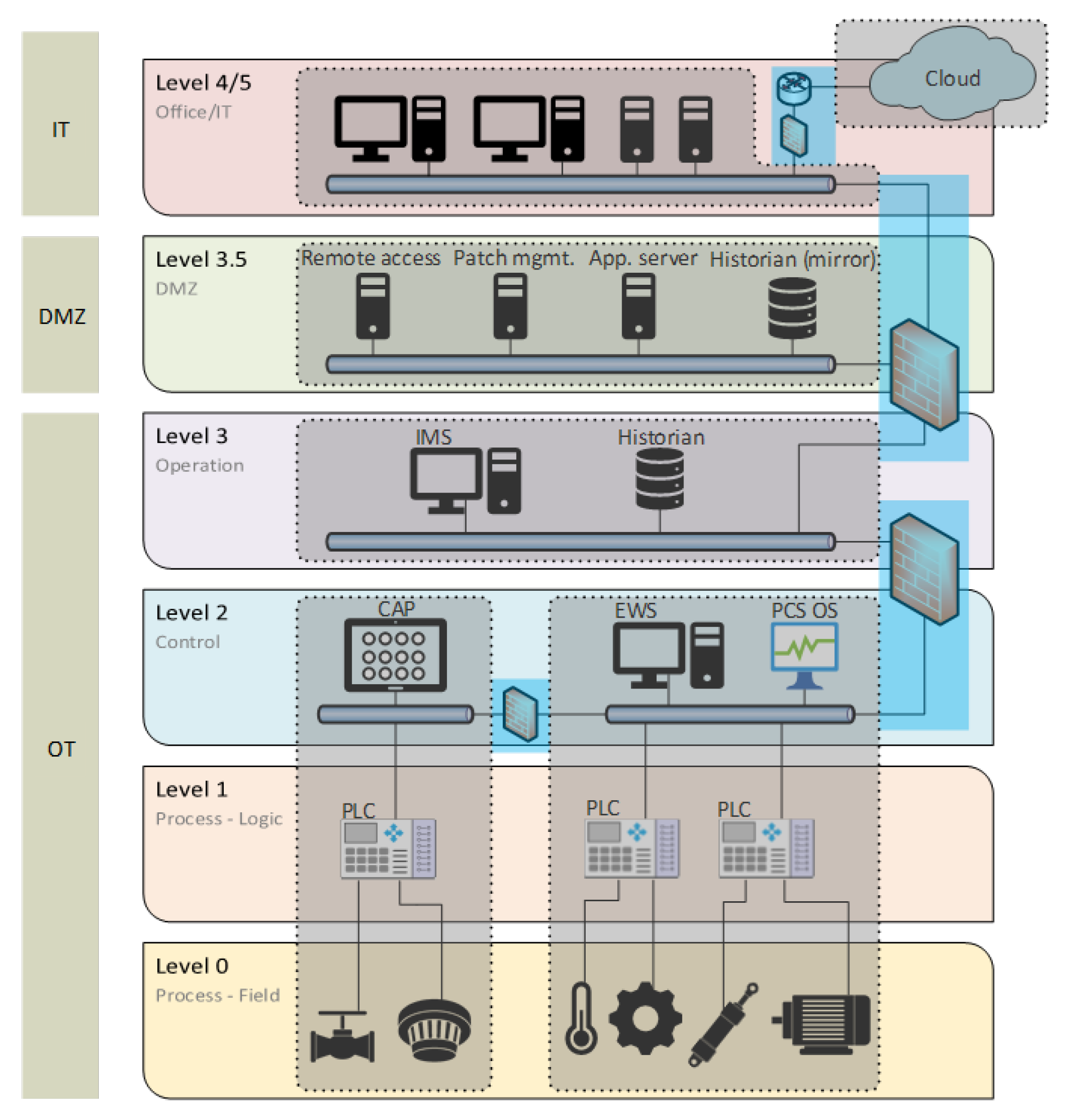
The OT system (industrial automation and control system) is a collection of personnel, hardware, software, procedures, processes, and policies involved in the operation of the industrial process and that can affect or influence its safe, secure, and reliable operation. The Purdue model [
7] is a generalized network topology model for industrial facilities, and is often used as a reference architecture to organize systems and their interconnections. As shown in
Figure 1, this model outlines the following principles:
The network topology is split into several levels, here named 0, 1, 2, 3, 3.5, and 4, mainly to organize sub-networks according to their main purposes.
The four lowest levels (0–3) cover the OT systems, while the highest level (4) is the IT system. The networks at levels 0–3 are sometimes referred to as the technical networks.
The separation between the OT and IT systems is ensured through a demilitarized zone (DMZ), referred to as level 3.5.
At each level, there may be one or more security zones, i.e., logical or physical grouping of systems that share common security requirements.
Conduits are used to define the secured link between each zone.
Figure 1.
Example of network topology for an industrial facility. In addition to the Purdue levels, the figure also shows how components can be divided into zones (gray) and conduits (blue).
Figure 1.
Example of network topology for an industrial facility. In addition to the Purdue levels, the figure also shows how components can be divided into zones (gray) and conduits (blue).
The PSA’s regulations refer to ICT systems as systems that address the need for the collection, processing, and dissemination of data and information (Cf. SF §15). Industrial ICT systems are generally used for OT systems that can control changes in physical equipment and processes, such as control and monitoring systems and security systems. The PSA’s area of authority in relation to ICT systems is mainly aimed at industrial ICT systems (OT systems) and, in particular, systems that have a barrier function (safety systems).
Safety has traditionally been linked to the need to protect people and the environment from the uncontrolled flow of energy as a result of accidental events and malfunctions. Technical safety encompasses many different types of technical barriers, while functional safety is used specifically for barriers implemented with electrical/electronic and programmable systems.
Safety is affected by ICT security in both IT and OT systems, and ICT events include both intentional actions and unintended incidents. Important attributes of the ICT system are confidentiality, integrity, and accessibility. Confidentiality, data protection, and information protection against intentional (malicious) actions are often emphasized in IT systems, while availability related to unintended events and error conditions is often emphasized in OT systems.
As a result of new links and dependencies between different systems, the energy area and information area will increasingly intervene.
It should be noted that the PSA’s regulations and traditional barrier management have primarily been about controlling energy, and that the information area has been relevant to the extent that it can adversely affect the energy area and have the potential to cause physical damage.
3. Standards, Guidelines, and Requirements for Independence
The following discusses some relevant standards and guidelines with emphasis on the requirements for independence and proposed solutions beyond what is stated in the Petroleum Safety Authority Norway regulations. It should be noted that there are several other relevant international standards and guidelines published by, e.g., ISO/IEC, NIST, ABS, and DNV, on the functional safety and security of OT systems.
3.1. IEC 62443
IEC 62443 [
8] is a series of standards designed to secure industrial communication networks and OT systems. The 62443 series is considered by many actors to be a natural framework for building and safeguarding security in OT systems and is, among other things, central to DNV’s class notation “Cyber Secure” for maritime OT systems [
9]. There is a limited focus on independence between 62443 series systems; however, some of the basic concepts are to divide systems and networks into appropriate zones and conduits, to group functions and devices based on criticality, and to minimize the consequences of undesirable incidents, see
Figure 1. Furthermore, zones and conduits will protect devices and the links between them from undesirable outside influence.
The philosophy of zones and conduits helps to create independence; however, there are no specific requirements for full isolation/independence. The 62443 series proposes choosing network topology and security barriers based on risk assessments, and thus the degree of independence may vary between different applications/interpretations of 62443.
A key term in IEC 62443 is the “Security Level” (SL). The concept focuses on the fact that zones and conduits should be graded at different levels (SL1–SL4), and is in IEC 62443-3-3 and IEC 62443-4-2 described as requirements for systems and components included in the different zones, respectively. Based on a risk assessment, these security levels represent a framework for determining the necessary protections and measures. The higher the SL, the greater the assessed risk and the higher the level of protection one should have against any malicious attacks.
The “Security Level Capability” a system or component can achieve depends on the degree of fulfilment of seven types of “Foundational Requirements”–FR. These are:
FR1—Identification and Authentication Control.
FR2—Use Control.
FR3—System Integrity.
FR4—Data Confidentiality.
FR5—Restricted Data Flow.
FR6 —Timely Response to Events.
FR7—Resource Availability.
For each of the seven basic types of requirements, IEC 62443-3-3 describes a number of specific system requirements (SRs) and associated requirement enhancements that must be met to achieve a certain level of security (SL), and, to meet, for example, SL2, all requirements that are applicable for level 2 must be met for all seven basic requirements categories (FR1–FR7). Similarly, IEC 62443-4-2 contains a series of requirements that reflect the system requirements at the component level.
The standard is extensive and rich and is well suited for use in OT environments. It is international and well-known and thus facilitates common understanding and effective interaction between actors. The main disadvantage of this series is that it is demanding to familiarize oneself with, as it is so extensive. This is especially true for smaller players, who may find that they have to devote considerable resources to familiarize themselves with standards rather than specific safety work.
Sub-standards 3-3 and 4-2 contain requirements for systems and components related to the Security Levels (SLs), respectively. Which of the requirements to be chosen arises from a risk analysis and also an assessment from those who will operate/own the systems (through establishing a so-called “profile” with requirements). Application of, and possibly certification according to, IEC 62443 is not necessarily enough to assert that a system is completely independent, but it is reasonable to expect a significant degree of independence in systems that meet strict 62443 requirements. The value of a certificate depends on the requirements included in the certification, and it is up to the certification bodies to define good requirements specifications.
3.2. IEC 61508
IEC 61508 [
2] is a generic functional safety standard and comprises, in total, seven parts of which the first four have the status as normative. That the standard is generic means that it applies to the design and operation of any safety system as long as it involves electrical/electronic/programmable electronic technologies. Manufacturers of safety systems at Purdue levels 0–2 will often apply this standard to qualify for for use in more than one industry sector.
IEC 62508, similar to the PSA’s Facilities Regulations (§§ 32–34), requires that the control system shall be independent of the safety systems. When elaborating on the independence requirement, the wording “sufficiently low” about the probability of simultaneous errors is used, which has its parallel in
Section 5 of the Management Regulations that barriers shall be sufficiently independent. However, IEC 61508 elaborates somewhat on the requirement for independence by specifying that common components, auxiliary systems, and operational and testing procedures should be avoided.
3.3. IEC 61511
IEC 61511 [
3] is the process sector specific standard that is based on IEC 61508. The standard has adopted the term “safety-instrumented system” (SIS) to denote any E/E/PE safety system that is separate from the (not safety-related) process control system (PCS). A reasonable interpretation of the standard is that SIS and PCS needs to be sufficiently independent as the SIS must be able to act upon events not managed by the PCS. The specific conditions for what is sufficient, is not defined by the standard. Here, the Norwegian Oil and Gas Association guideline GL 070 [
6] has proposed some examples for when common components can be allowed, considering that a sufficient capability and priority of SIS-functions is ensured.
3.4. DNV-RP-G108
DNV-RP-G108 [
10] has extracted the most important elements for maritime OT systems from a range of IEC 62443 standards. DNV-RP-G108 is a useful summary of the most important content of IEC 62443.
DNV-RP-G108 (September 2017 version, revised in October 2021 in terms of the name change from DNV GL to DNV) is based on part 2-1, 2-4, 3-2, and 3-3 of the IEC 62443 series, and it is likely that new relevant parts and/or new versions of the aforementioned parts will be published. Furthermore, DNV plans to update DNV-RP-G108 in 2022. One should therefore be aware of which versions from the IEC 62443 series and which version of DNV-RP-G108 are in effect at all times, so as not to miss new information.
4. Technological Trends, New ICT Systems, and Industrial Internet of Things (IIoT) Solutions
In this section, technological trends, technologies and solutions that may lead to new dependencies and possible negative influences, partly as a result of new systems being able to be connected to technical networks are described. The list of technologies and concepts is not meant to be exhaustive but rather to reflect some of the technologies and trends that were discussed in the interviews with the industry.
A main challenge with the new solutions is that traditional layering is blurred when components are allowed to communicate autonomously, for instance, by use of Industry 4.0 concepts. The purpose of this chapter is to describe some of the key technologies and concepts that may influence the data exchange within OT and between OT and IT.
4.1. Industry 4.0
The term Industry 4.0 [
11] describes the fourth industrial revolution, or rather an evolution in which the internet merges with production and products. The Internet of Things (IoT) is a main driving force in this development, bringing the physical and digital world together, and it consists of four main parts: things, internet connections, data, and analytics.
In connection with Industry 4.0, new platforms are being explored for the seamless interconnection of equipment and data sharing. Industry 4.0 originated in the German manufacturing industry; however, the concept has gained acceptance worldwide as part of the general digitalisation trend.
With increased demand for efficiency within the oil and gas industry, technologies, such as cloud computing, big data, and IoT, are gradually being applied, replacing, or evolving traditional industrial production technologies. To enable this transition, the oil and gas industry needs to embrace the nine pillar technologies of Industry 4.0: autonomous robots, digital twins, cloud computing, 3D printing, augmented reality, big data, the industrial internet of things (IIoT), cybersecurity, and system integration [
12].
Initially, the petroleum industry emphasized the development of cloud solutions where large amounts of data from facilities are collected and shared, but this has been done without major changes in the underlying networks and systems in OT. At the same time, new initiatives are being launched that target both the design of OT networks and equipment, both from German and global organizations. This includes requirements and solutions for integration and data exchange between field equipment, controllers, operator stations, servers, and clients for various applications.
At the core of the digitalisation process for Industry 4.0 lies the Reference Architecture Model (RAMI4.0), which describes how an asset can be converted into a digital representation and processed in the digital world [
13]. While RAMI 4.0 provides the overall framework for how system integration should occur, there are several competing platforms that describe how this can be solved practically within both OT and the IT network, including, for instance Open Process Automation (OPA), Modular Type Package (MTP), and Namur Open architecture (NOA). Namur is covered in more detail in
Section 4.3.
In summary, great expectations have been created for the gains by using Asset Administration Shell (AAS), which is the implementation of a digital twin to realize RAMI 4.0. At the same time, this raises concerns that the traditional divisions built into networks and between systems may be erased. Both tools and code, for example for AAS, are published and further developed through open websites (github) as a kind of industry effort. Despite the fact that the various platforms (OPA, MTP, NOA, and AAS) claim to safeguard cybersecurity, the solutions also represent the risk of new vulnerabilities through new network structures and ways of exchanging data.
4.2. OPC UA
Open Platform Communication Unified Architecture (OPC UA) [
14] is a standard for industrial communication and information modelling that was first published in 2008 and has been increasingly adopted in recent years. OPC UA is, as the name implies, an open standard, and the purpose of the standard is to ensure the secure and platform-independent exchange of data at the field equipment level and between OT and IT.
Finding good solutions for this is becoming increasingly relevant as more field data becomes available. The OPC UA has been adopted by several sectors and is often described as the protocol that can bring data from the field equipment to the office network and/or cloud. The process industry often represents this exchange of data using the “ISA-95 reference architecture/Purdue model”. The OPC UA has also become more international as the IEC has issued a number of OPC UA standards.
4.3. Namur Open Architecture
NAMUR Open Architecture (NOA) [
15] is a framework that will simplify the introduction of principles and solutions related to Industry 4.0, digitalization and industrial IoT in the process industry. NOA describes how information exchange between process control systems and the new area “monitoring and optimization (M+O)” can be performed with open interfaces based on data diodes to ensure adequate information security.
NOA is intended for existing brownfield processing plants where, in terms of cost and complexity, it is unrealistic to change the basic principles of the automation pyramid and the Purdue model’s layering. NOA shall thus safeguard the integrity of process control systems (OT) while making data and information from controllers and I/O devices available for further analysis and processing in the IT domain (M+O).
In this context, a concept called “NOA diodes” will provide one-way communication with adequate mechanisms for information security. NOA also defines a solution for communicating, e.g., new set points for process control from M+O back to the OT systems, but details of how this will be implemented as of November 2021 are not fully specified.
An important limitation of NOA is that communication to and from safety instrumented systems (SIS) is not part of the standard. It is explicitly stated that the concepts in NOA should not be used for this purpose. Awareness in the petroleum industry around this will be important in order to ensure independence by reducing the risk that NOA will, in the future, be used to extract information from systems that safeguard functional safety.
4.4. Digital Twins, Big Data, and the IIoT
There are several definitions of a digital twin. In 2010, the National Aeronautics and Space Administration (NASA) stated that a digital twin is an “integrated multi-physics, multi-scale, probabilistic simulation of a vehicle or system that uses the best available physical models, sensor updates, fleet history, etc., to mirror the life of its flying twin” [
16]. According to this definition, the digital twin is a detailed simulation model of a system, with the intention to reproduce its physical behaviour as closely as possible in a digital world [
17].
However, a more suitable definition for the purpose of using the digital twin for asset performance management was defined by Hicks: “A Digital Twin is an appropriately synchronised body of useful information (structure, function, and behaviour) of a physical entity in virtual space, with flows of information that enable convergence between the physical and virtual states” [
18].
Big data can be defined as a large amount of unstructured or structured data from a variety of sources [
12]. The potential of big data has not yet been fulfilled within the oil and gas industry, even though large amount of data are generated on a daily basis. A great amount of historical data are also available, and it is expected that the use of this data could produce great value. However, in the same way as for digital twins, the flow of information that can be required for some of the relevant applications of big data can introduce new vulnerabilities.
The industrial internet of things (IIoT) refers to a subset of IoT that is focused on improving safety and efficiency in industrial environment where failures can lead to dangerous situations. IIoT integrates sensors, instruments, and communication technology to enable data collection, exchange, and analysis to with the intention to improve productivity and efficiency as well as other economic benefits [
12].
The flow of information required for digital twins, big data, and the IIoT can, as already stated in
Section 4.1, introduce new vulnerabilities and dependencies that must be appropriately handled.
4.5. Data Diode
A data diode is a physical network component that, when connecting network
A with network
B, can guarantee that data can flow from
A to
B, but not from
B to
A. There are a number of different ways to implement a data diode; an early suggestion from Kang and Moskowitz [
19] involved a trusted process that wrote to a communication buffer (i.e., a queue), and another trusted process that read from the other end of the communication buffer.
However, many such data diodes were designed to ensure confidentiality in situations with data moving from a lower classification level (e.g., “Confidential”) to a higher classification level (e.g., “Secret”). This is in line with the Bell–LaPadula model; however, in our case, the situation is the other way around: we want to communicate data from a high-integrity zone to a zone with lower integrity requirements; and we are not concerned with confidentiality but concerned that the equipment in the latter zone cannot affect equipment in the former (functional independence).
The solution from Kang and Moskwitz was quite complicated, and later solutions exemplified by Jones and Bowersox [
20] were rather based on the use of an LED and a phototransistor. In principle, this is the same as taking a fibre-optic interface where you physically remove the return fibre.There are a large number of data diodes from different providers that have been evaluated according to the Common Criteria at the highest level [
21].
The data diode is an attractive solution in the way that it can physically guarantee that A is independent of B if the data diode represents the only connection between the two. In the meantime, it may present a problem if there is a need for A to be updated or reconfigured from B.
In this case, there would be a need for some way to bypass the data diode; on a device, this may be that maintenance personnel physically travel out to make the changes, but this of course appears to be very cumbersome. In practice, this means that many people who use data diodes at the same time create “additional solutions” that make it possible to connect to A from B (and elsewhere); this would mean that the independence guarantee represented by the data diode would no longer be real.
4.6. Edge Devices
Edge devices appear to be increasingly used to extract data from the OT systems. There is no unambiguous definition, other than that they are used on the edge of what is otherwise available by IT/OT. The technology and protocols are also not unambiguous but depend on the supplier and who will retrieve data. There are several reasons why these devices are used:
Information may be lost on the way through the layers of the Purdue model because one may want to reduce bandwidth and storage needs, such as:
- -
Only sending averages for a time interval.
- -
Not sending over all values.
- -
Updating values only when they have changed since the last time.
One wants to retrieve information other than what is available and mounts IIoT devices that can extract other information.
This solution initially looks permissible; however, one must bear in mind that, in order to realize a lossless transfer, one must use a protocol that has messages both ways. One must either inquire about values or sign on to receive, and this requires good protection to prevent anything else from joining these messages.
In particular, where information is extracted from devices that are part of safety functions, it is critical to protect against “stowaways”. To avoid problems with operations, one must generally also protect the PCS. Such protections can be demanding especially for “cheap” devices where one does not have enough computing power and battery capacity, especially in wireless devices and also, for example, in a pressure transmitter.
4.7. Handheld Devices
Handheld devices are an example of new ICT systems that are connected to technical networks. The information presented in handheld devices may be used as a substrate for work in the processing plant, for example, to check the pressure and conditions of part of the process before opening a manhole for internal inspection and work. Even if all formalities, such as work permits, are in order, one can imagine that a dangerous situation could occur if the handheld device incorrectly shows that the pressure has been evacuated, and the operator opens the manhole because he trusts this information.
4.8. Wireless Instrumentation
Wireless instrumentation presents some of the same challenges as handheld devices. A wireless detector can be connected to the F&G node with its own dedicated network that has nothing in common with other networks so that the information does not have to be brought down through the DMZ. The fact that the detector uses a protocol based on the same principles as the PROFIsafe does not provide a satisfactory solution to protect against such penetration of the DMZ.
5. Measures to Resist Cyberattacks
The importance of cyber security in the petroleum domain has been acknowledged for more than a decade [
22,
23], and after some spectacular attacks in the broader energy sector [
24,
25], industry actors would be justified in feeling that cyber threats are coming uncomfortably close to home [
26]. Common good practice for secure computing is largely applicable to OT systems [
27], and can profitably be combined with, e.g., the NIST Cybersecurity Framework [
28].
A cyberattack may target one or more systems within OT or IT, often by first obtaining unauthorized privileges at some ICT resources that can be used to control and command the attack. If a System A can be subjected to cyberattacks from a System B, this would be a threat to the independence of System A. Consequently, a system will have to be protected from cyberattacks to truly be independent.
In this context, we are most concerned with cyberattacks that can affect the integrity and availability of systems and data and which can ultimately affect independence. In terms of data, we can most often solve this by building blocks of encryption, message authentication, and/or digital signatures. It is also common to divide into different zones, which often assumes that different forms of conduits are used for communication between the zones. A special case is the use of data diodes to ensure that communication can go from one zone to another but not back again. These topics are described in more detail in the following subsections.
Software can be subjected to attack, and a successful attack can enable an actor to change the behaviour of a system; this may affect the independence. For proprietary software, it is important to follow good software security practices to make sure that the software does what it is intended to do, even when exposed to a malicious influence. Of course, this should also be sought for software from an external supplier; however, there is often less control in that case. Thus, it will most often also be necessary to use network mechanisms that limit which actors are able to (attempt to) communicate with software that may affect functional security.
5.1. Communication for Functional Safety
IEC 61508 states that when a safety function is dependent on communication, the communication system should be regarded as a component of the safety function. Functionally safe communication can then be achieved by one of two methods:
The entire communication channel (including the endpoints) is designed, developed, and validated according to the IEC 61508 and either IEC 61784-3 or EN 50159.
Parts of the communication channel are not designed, developed, or validated in accordance with IEC 61508, are endpoints only (transceiver). In this case, necessary measures for safe error handling of the communication system as a whole shall nevertheless be implemented in accordance with either IEC 61784-3 or EN 50159.
Method I is called “whitechanneling” and requires the development of a dedicated communication system solely for secure communication. In most cases, this is very time-consuming and costly and is thus not widespread. Method II is called “blackchanneling” and involves adding safety features to the endpoints of the communication in order to avoid certification of the entire communication system.
IEC 61784-3 for industrial communication networks defines principles for the transmission of safety-related messages between participants in a distributed fieldbus network in accordance with requirements for black channel in IEC 61508. IEC 61784-3 also describes one set of profiles for safe communication for a selection of fieldbus standards:
Profile 1: Functional safety with FOUNDATION Fieldbus.
Profile 2: Functional safety with Common Industrial Protocol (CIP).
Profile 3: Functional safety with PROFIBUS and PROFINET.
Profile 6: Functional safety with INTERBUS.
Profile 8: Functional safety with CC-Link.
Profile 12: Functional safety with EtherCAT.
Profile 13: Functional safety with Ethernet POWERLINK.
Profile 14: Functional safety with Enhanced Performance Architecture (EPA).
Each of these profiles is specified under IEC 61784-3-x, e.g., IEC 61784-3-3 addresses functional safety for PROFIBUS and PROFINET—a profile called PROFISafe. The secure communications profiles are based on the underlying protocols and are transmitted on the same network/cable as other messages. However, the utility message is extended with the following information:
A safety code that should be able to detect accidental errors of a random and systematic nature in messages.
Unique sender and recipient identification for the message.
Sequence number of the message.
When the next message should arrive at the recipient.
Although the profiles in IEC 61784-3 address various communication channel error modes, the standard is somewhat inadequate when it comes to information security coverage. Reference is made to IEC 61784-4 for fieldbus-related security and to IEC 62443 for general security, but without any further explanation or requirements regarding how it should be implemented.
Unfortunately, it is not difficult for unauthorized persons to manipulate messages without it being detected by the mechanisms of these profiles; this can affect safety. Neither is there any protection against other traffic being adversely affected. The only thing these profiles ensure is that the recipient goes to a predefined safe state if any error is detected on the transfer.
In the context of closer integration between process control and safety systems and the fact that several different industrial ICT systems and IIoT solutions are connected to technical networks, existing security systems should be required to be certified in accordance with the regulations. IEC 61784-3 has sufficient mechanisms for information security. Protection against unauthorized access can then be done in two ways:
Of these two procedures, the first will require a change in communication elements in the safety function, with subsequent time-consuming and costly re-certification. The second procedure avoids changing the SIS by preventing unauthorized access to the communication channel using zones and conduits as defined in IEC 62443.
5.2. Encryption
An important vulnerability in today’s OT systems is that they often contain older equipment that does not have built-in support for cryptography. This means that high data integrity depends on good shell protection. Digital signatures or message authentication codes (MAC), which provide the ability to verify that data is authentic and has not been altered, are not usually used in OT systems. DNV-RP-G108 [
10] contains the following recommendation:
There has been a previously widespread misconception that encrypting a communication channel (for example, in the form of a Virtual Private Network) makes it impossible to manipulate the data transmitted without it being detected by the recipient. In recent years, however, the IT industry has had to accept that such guarantees can only be given if one of the more closely defined protocols for authenticated encryption is used, such as AES-GCM [
29] or AES-CCM [
30].
If quantum computers become available in the short term, this will lead to dramatic changes in which algorithms and key lengths provide sufficient levels of security [
31]. If this is to be taken into account, this may, among other things, have the following consequences:
Today’s public-key algorithms that rely on discrete log or factorization of large numbers (Diffie–Hellman, RSA, and ECC are the most common examples) need to be replaced with quantum-safe options.
The key length of symmetric encryption algorithms (AES) must be doubled—256 bits or more.
The length of hashes must be doubled (SHA3-384 or SHA3-512).
As of today, there is no consensus on which public-key algorithm to choose; however, various alternatives are being developed. Authenticated encryption does not appear to be an issue that receives a great deal of attention in the petroleum industry; neither is quantum-proof encryption.
Depending on the choice of profile in IEC 62443, encryption requirements may apply, and the OPC UA may also include encryption. There are also drawbacks to using encrypted messages within OT due to the fact that signature-based IDs (Snort, Suricata, Bro…) will not be able to detect intrusion attempts. Network monitoring will then also become more difficult. For individual applications, it is possible to consider proxy solutions that decrypt the traffic entering/exiting specific zones.
Encryption between devices in OT has not been implemented on Norwegian facilities, partly because the equipment used today rarely supports the encryption of traffic, and partly because encryption/decryption requires resources and may come at the expense of response time and the possibilities for exchanging information between the individual systems, and the operator interface may also be slower. Shell protection in the form of zones and conduits according to IEC 62443 may, in the short term, represent a better solution for OT systems.
There are SIL 4 certified hardwired safety systems in accordance with IEC 61508, where logic cannot be influenced via ICT systems. The logic is not vulnerable to ICT threats, and information and status can be extracted, for example, with OPC (but the OPC part has not yet been certified according to current IEC 62443 standards). This means that logic does not need protection against ICT threats, while the information on OPC has the same challenge as other software-based infrastructure.
5.3. Properties of Zones and Conduits
The concept of zones and conduits as illustrated in
Figure 1 is often pointed to as the solution to protect against undesirable external influence; however, these concepts do not guarantee independence, partly because the scope of proposed measures will depend on the application, established SL, what requirements are actually implemented, and the fact that all systems/components within a zone cannot necessarily be implemented with the given SL requirements for the zone.
Requirements for the implementation of zones and conduits are given in different parts of the IEC 62443 standard series. Below are some issues that can be solved if relevant measures have been implemented:
A conduit between two zones can be made to protect against undesirable influences, also through the conduit, but this is not part of the requirements that follow directly from the level (SL, Security level) and other requirements for conduits and zones in IEC 62443. Such protection must either be realized in the conduit or at the receiver if one is not to be able to influence SIS from other systems. (IEC 62443-2-4, SP.05.02). This means that requirements of the type stated in NOG 070 are still necessary.
In IEC 62443, there is a possibility that the safety systems (SIS) may be logically or physically separated in zones that are different from those containing those systems that are not safety systems (PCS). If they cannot be separated, both must be in the same safety-related zone. (IEC 62443-3-2 Chapter 4.4.4). For devices in the same zone, the standard does not provide any protection or independence.
Configuring SIS on remote access may prevent configuration. This must also be verified by an independent third party. (IEC 62443-2-4, SP.05.09)
The measures found in 62443-2-4 are described as opportunities (or capabilities) that a supplier should be able to offer a plant owner and are not explicitly linked to the security level (SL). On the other hand, the requirements of IEC 62443-3-3 (for systems) and IEC 62443-4-2 (for components) are linked to a fixed SL, which in turn shall appear as a result of risk assessments. However, it is the plant owner who ultimately decides which requirements should actually be implemented, typically by establishing a “profile”. It is therefore essential that this profile includes the requirements that one believes are important for providing as much independence as possible.
5.4. OPC UA PubSub as an Approach to Computer Diodes
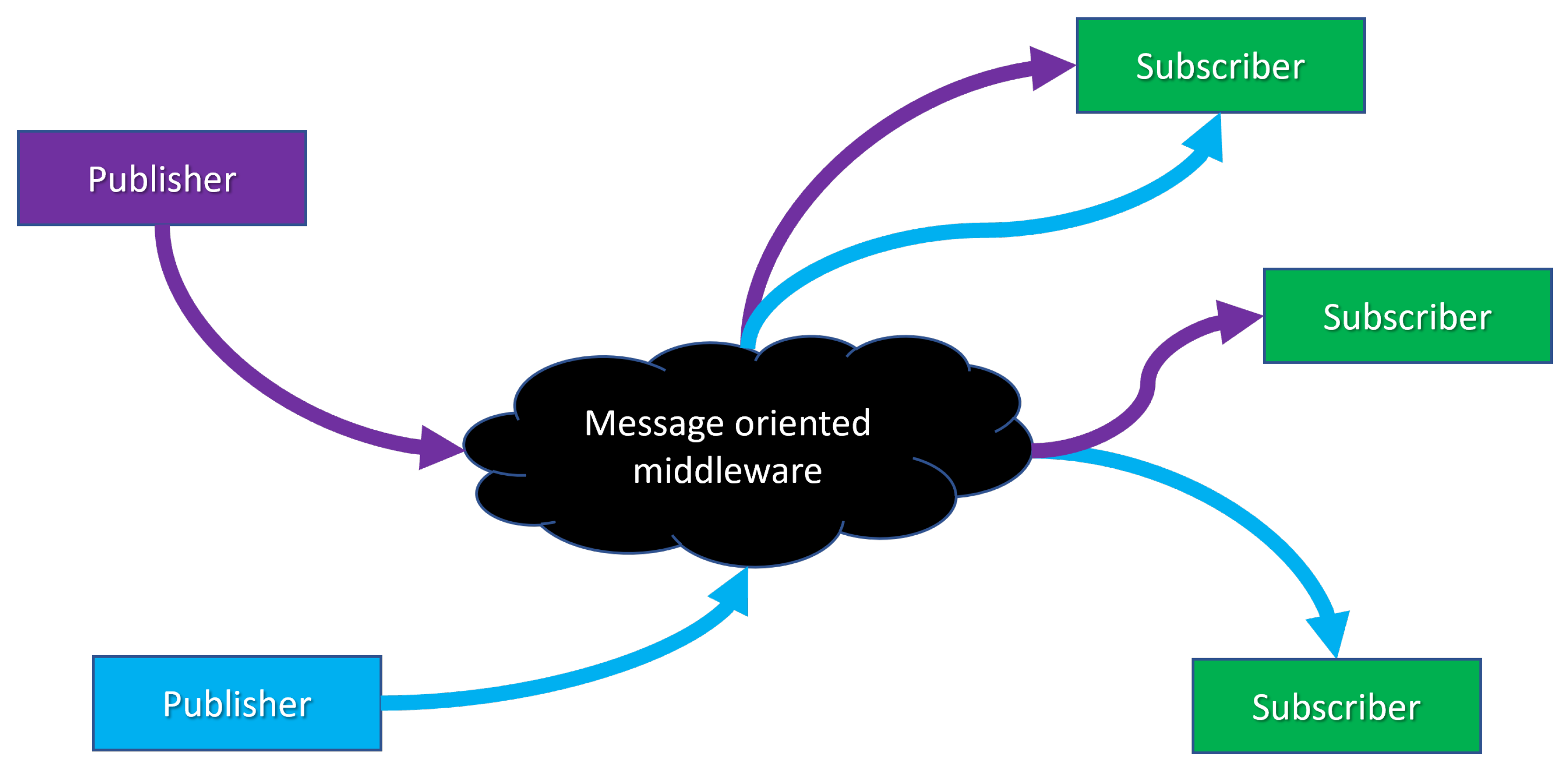
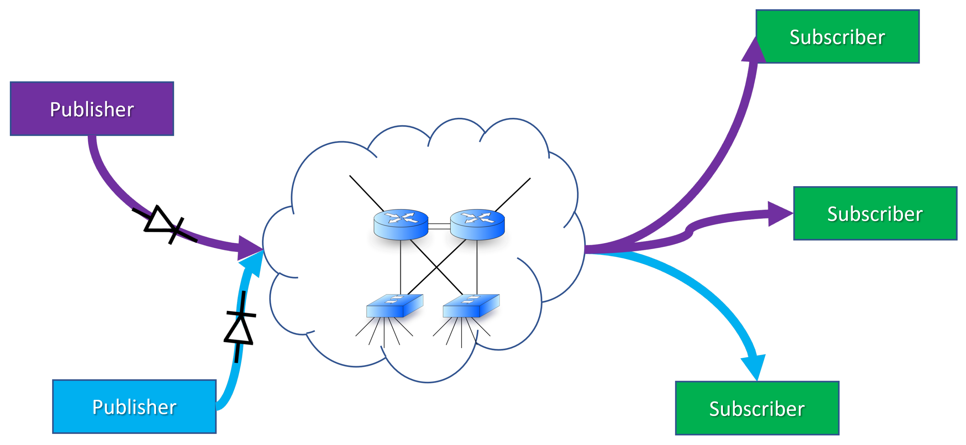
Publish-Subscribe (PubSub) is described in OPC UA part 14 [
32]. The model can be illustrated as in
Figure 2; one or more entities that publish data and one or more entities that subscribe to data. This is done through a middleware that can be implemented in different ways. Essentially, all the devices can be “normal” OPC UA devices that communicate in the usual way, but one explicit option is to use a UDP datagram without a receipt. In this case, it will be possible to place a “unidirectional gateway” (i.e., data diode) between the manufacturer and the consumer (see
Figure 3).
PubSub claims to support signing or signing and encryption (although references to a shared key between publisher and subscriber would indicate that what is involved is a Message Authentication Code rather than a digital signature). Individual data items are grouped into a “DataSetMessage”, and several of these can again be grouped into a “NetworkMessage”, which eventually makes up the payload in a transport protocol message (in our case, UDP). If there are several subscribers, one can use UDP multicast addresses; however, for our purposes, it is assumed that UDP unicast addresses will suffice.
The data field in “DataSetMessage” consists of the information specified in
Table 1. The most important ones here are an ID that identifies the sender, a sequence number, and a timestamp.
UDP makes no guarantees about timeliness, delivery receipt, order, or duplicate protection. When using a data diode, it will not be possible to request the retransmission of missing packets; however, it is possible to send multiple copies of the same package. This must then be configured if there is a communication channel with too much packet loss. The sequence number then makes it possible to discard the duplicate packets [
32]. If one uses UDP, consumers must probably be adapted so that they can work even if some packages do not arrive.
5.5. Zero Trust Versus Shell Protection
In the early days of the computer age, computers were monolithic colossuses that filled entire rooms, and the only form of communication was done in the form of stacks of punch cards that were carried in and out. However, the world moved on, and modern computer networks saw the light of day.
At one point, computers from different organizations began to be connected, and when the Internet became public in the late 1990s, anyone could connect to any computer system. This also left the way open to attackers, and many organizations found that securing each machine was difficult. Thus, shell protection of local area networks was implemented in the form of a firewall; to quote Bill Cheswick: “a hard shell around a soft, chewy center” [
33].
In recent years, shell securing with firewalls in IT networks has proved challenging, partly because a number of services now require the creation of “holes” in the firewall for them to work, partly because today there are so many mobile devices that are brought into corporate networks, and partly because the use of cloud computing has increased to a great extent. Thus, a new trend that almost brings us back to the starting point has become popular: zero trust computing [
34,
35].
The concept is that security should no longer be based on shell protection where all devices inside the firewall are trusted but instead require all devices to authenticate themselves to any other device with which they mean to interact. Furthermore, all devices must then also be authorized in order for them to be allowed to interact with a given device.
Zero Trust computing requires mechanisms for key distribution and key management in place; it often involves a PKI, although there are also other ways to do it. This also means that one must rely on the use of cryptographic mechanisms in OT networks that would use this.
6. Possible Dependencies and Negative Influences
In this section, we discuss how new solutions can lead to possible dependencies and negative influences and also reflect on whether the requirements in IEC 61508 and IEC 61511 for independence can be said to be fulfilled or not.
6.1. What Do We Mean by Negative Influence?
With “negative influence”, we consider here when an error or incident in a system or its component can impair or prevent the functioning of another system or component of another system (a so-called dangerous failure if the system affected is a safety system). This could be due, for example, to common components, a functional or physical dependency, or common external influences.
Negative impact can also be associated with failures or events that affect the production capacity of other systems or components (but do not prevent the safety function itself). For example, a valve in the production line shuts down as a result of a failure of the hydraulic system (so-called safe faults). This is also negative influence, both in terms of regularity and on the basis of the fact that shutdowns and start-ups themselves represent a risk. However, our primary focus in this report is safety-critical (dangerous) errors.
A key question then becomes whether the PSD or other safety systems, such as the ESD and F&G system, can be adversely affected as a result of failures in other systems. For example, can they negatively affect each other, can they be negatively affected by the control system, or can they be adversely affected by other ICT systems and IIoT solutions, including links to provider-based cloud solutions outside the OT domain?
6.2. New Dependencies and Links
Even in layered solutions that follow the Purdue model, there is a challenge when it comes to reducing the potential negative impacts of having connections between the different systems. This can relate, for example, to the possibility to exploit the connections to send unauthorized signals or links via the operator interface. It is very challenging to show that any abnormal event occurring in one system cannot adversely affect another.
Some operate with a dedicated safety network that separates SIS from the other systems; however, even with such a topology, there will be connection points, such as to a common operator interface. Having a separate safety network helps reducing the load of traffic between devices and systems within this network but is not able to ensure that all safety-related information is protected from other systems due to the need to also communicate over other shared networks.
Zones and conduits according to 62443 can provide protection against undesirable external influences; however, this does not guarantee full independence. Within a zone one has the same challenges as for today’s solutions, and through conduits one can, in principle, have a negative impact by transferring the wrong value. As long as the value is within legal limits, it may have a negative impact. This is comparable to the fact that 4–20 mA is within the legal limit, but in any case, 16 mA can lead to SIS not receiving 8 mA, which should have resulted in a safe action.
The independence that is achieved with segmenting networks is to ensure some possibility of control over the series of links that are established between the zones. However, the definition/delineation of a system becomes unclear when different functions are placed in different zones. According to DNV’s RP-G108, different systems should be segmented into different zones, as long as they do not have functional or operational dependencies that require them to be in the same zone.
This approach is challenged by the new solutions that have been outlined with more/many links across zones. Examples of this are 5G base stations that will be used across all layers of the Purdue model and future flattening of the automation pyramid where everyone can communicate with everyone as defined by the OPC UA.
In the case of remote connectivity (or other cross-zone links), there is no longer a clear connection between the system and zone. It can be argued that a system spans several zones, as its functions are located in several different zones; however, this is not in line with the recommendation to have different systems in different zones.
Newer technologies, such as edge devices and IIoT devices, face challenges if information is to be retrieved from devices that are part of the safety systems as long as they use a lossless protocol that must send either requests or receipts to the device. Here, it is also important to note that NOA, which defines how to retrieve information from OT to IT using data diodes, does not include safety systems.
If you look at the IT/OT systems as a unit, there may be a good deal of common components, although this can, of course, vary between installations. If these are not critical today, one must focus on whether they can be and especially whether they can be used as attack points. Some examples of such are:
Firewalls and other network components.
Human–machine interfaces.
Configuration Tools.
Clock systems.
Field Equipment Management Systems.
5G.
Domain controllers.
Backup Systems.
Hardware and software (hypervisor) for virtualization.
Active directories.
Authentication Systems.
Key management (applicable for all authentication/encryption schemes and for Zero Trust).
It is difficult to say anything generic about the extent to which these are used by the OT systems, but if one is to assess attack points and dependencies, these must be included. To remove these possibilities for dependent errors, one should consider whether IT and OT should have their own functions. One must not forget about the possible dependencies that can exist already in today’s solutions with common networks and signals between devices both within SIS and between SIS and PCS.
In some of the initiatives to integrate information from the IT/OT systems into cloud solutions or otherwise, we see that the levels of the Purdue model are under pressure, and that these systems are opened up for edge devices, IIoT, and others to harvest information and bring it out. Although each connection seems well secured, the large number of connections is a challenge as the protection is fresh and needs to be updated and maintained. New challenges related to cloud solutions are also introduced at 5G, where mobile operators can access the configuration and setup of 5G infrastructure on facilities via cloud-based services.
7. To What Extent Will the Requirements for Independence Be Met?
We can first conclude that it is difficult to give a definitive answer as to whether the requirements for independence in IEC 61508 and IEC 61511 are met. Both standards open up for allowing some degree of dependency, as long as the dependencies are identified and managed so that the ability of each safety function to act independently is not impaired.
Over time, the industries have established a set of design and operation principles and strategies where an adequate level of independence has been achieved. These principles and strategies are partly reflected in regulations (such as the PSA regulations and their guidelines) and national and international standards. What is learned from our study is that security threats and cyber attacks are able to impair the OT and IT systems in new ways, meaning that dependencies that were acceptable in the past can now pose a risk.
The fundamental requirement that any SIS system should be able to perform independently from other systems (including PCS) are more tangible and the following observations and comments can be linked to them:
Current risk and reliability analyses contain limited detailed assessments of new hazards and threats related to existing links and dependencies between systems.
As a result of increased complexity and multiple links, it is very challenging to show that any error that can occur in one system cannot adversely affect another system.
Suppliers generally do not appear to have standard documentation showing that their solution provides full independence and/or does not adversely affect other systems.
The operators also do not have any such documentation.
If we attempt to answer the question in the headline, the answer must be: The requirements for independence may be met; however, there is no documentation to show it.
This discussion can also be linked to the PSA’s new definition of the risk concept, which, in the guidelines for Section 11 of the Framework Regulations, states that risk means the consequences of the activities with associated uncertainty. In the clarification of “associated uncertainty”, it is that the degree of complexity in and knowledge of the phenomena, systems, and operations one faces should be emphasized in risk management.
Since today’s risk and reliability analyses primarily focus on how dependencies may be impaired from uncontrolled physical phenomena and operational errors in the process, and documentation of independence considering the new risks of cybersecurity is somewhat absent, one can conclude that the uncertainty, and thus the risk, associated with possible unknown dependencies is considerable.
8. Recommendations for the Industry
This section summarises the identified challenges along with our recommendations and proposed measures for the industry to ensure that the process safety and security systems shall perform their intended functions independently of other systems.
Challenge: Common functions and systems. Avoid or reduce the use of systems and components common to SIS and other IT/OT systems and, where it cannot be avoided, establish multiple barriers to prevent attacks against common solutions.
Challenge: Limited protection against digital attacks. Even though there are a number of measures for SIS and PCS, further measures are needed. One must ensure that these systems are protected from attacks in other ways.
An obvious protection is to use hardwired safety systems where the logic is implemented in electronics without software or CPU. Measures to reduce the safety consequences of digital attacks include electric fail-safe designs combined with non-programmable means to cut power, which will give the operator a last resort. Process design where secondary barriers are mechanical non-programmable devices, such as Pressure Safety Valves (PSVs), will also reduce the safety consequences of digital attacks.
Challenge: Separate networks for SIS and PCS. One should not rely on separate networks to provide full independence but should introduce/retain other measures to avoid dependencies and undesirable influences.
Challenge: Data diodes. Ensure that other methods are used if one has to temporarily enter OT components from outside, so that the data diodes must not be disabled or weakened to allow this type of communication.
Challenge: PROFIsafe provides poor protection against attacks.
Ensure that such communication is further protected from undesirable influences by additional mechanisms when it may be available from outside (zones and conduits, etc.).
Challenge: Independence requirements between PCS and SIS. Independence is a prerequisite in both IEC 61508 and IEC 61511 in order to meet SIL. Ensure that the requirement is met even after the OT systems have been commissioned and the necessary exchange of signals is implemented.
Challenge: Inadequate analyses and documentation. Conduct more detailed and targeted analyses that look specifically at links and possible dependencies between systems also in relation to ICT threats.
Challenge: Vendor certification. Assess whether/how certification of equipment and working methods will be a cost-effective measure.
Challenge: Disappearing layers in the Purdue model. Ensure that the protection provided by the layers of the Purdue model is safeguarded in other ways.
Challenge: Increased network complexity and dependencies. Limit the complexity and number of connections by questioning the necessity of each connection and allowing only connections that are deemed strictly necessary. Connections that, individually or in aggregate, generate an unacceptable risk of adverse influences on OT systems should not be allowed.
Challenge: Extraction from local 5G systems. If 5G is introduced as a medium of communication, it must be ensured that the use of common key components cannot lead to undesirable incidents and dependencies.
Challenge: Edge devices. Handheld devices are initially used to provide information to the field operators. This can easily change due to the fact that the handheld device can also send information to OT. Operators may mistakenly rely on the information from the handheld devices.
Ensure that information on these devices is not used for security-critical operations and that information from them does not affect OT systems.
Challenge: Use of IEC 62443. The use of IEC 62443 does not guarantee independence but can contribute to this if the right requirements are identified and implemented Develop “profiles” based on the requirements of IEC 62433 as documents and justify the choice of relevant requirements that contribute to independence.
Challenge: Misuse of NAMUR OA for SIS. Namur Open architecture (NOA) is considered by many to be a promising initiative to extract information from existing facilities, but it is explicitly stated in it that it should not be used against SIS (“out of scope”). Ensure that only solutions adapted to it are used for linking to SIS.
Challenge: Insufficient SIS security requirements. Having too low requirements (SL level) regarding SIS is challenging. With lower staffing, the use of edge units, and IIoT, one will likely have to grant access to more people and organizations more often and perhaps permanently through the access system. Assess whether the SIS zone should have higher protection so that it is also well protected from both accidental and intentional influence from those who are deliberately let through into the IT/OT systems.
9. Conclusions
This research project focused on the challenge to maintain independence between control and safety systems as required by IEC 61508, which is the basis for designing control and safety systems for offshore facilities. This independence is challenged by the increasing demand for data collection and remote access to improve operations and compensate for reduced manning offshore.
To meet the challenges against independence, several recommendations have been given to counteract but still allow the retrieval of information from the safety systems. Although IEC 62443 is part of the solution, it is challenging to select the adequate measures to achieve the necessary independence and to develop profiles that can be applied. Cybersecurity barrier management also needs to be developed based on experiences with safety barrier management.
We recommend that regulatory authorities highlight the importance of ICT barriers. We see an emerging need for the definition of barriers to be expanded from controlling energy to also encompass the information area, e.g., that protection against unwanted data flow and the subsequent negative impacts is treated as a barrier function.
Even though key parts of IEC 62443 are not available in updated versions, we recommend that the regulatory authorities should be included in their regulations and hence refer to (parts of) the IEC 62443 series in their guidelines. In particular, IEC 62443-3-3 contains several system requirements (and substandard 4-2 corresponding component requirements) that, if implemented, can contribute to independence.


 ,
, 


