Article

Seismic Performances of Masonry Educational Buildings during the 2023 Türkiye (Kahramanmaraş) Earthquakes

1
Department of Civil Engineering, Bitlis Eren University, Bitlis 13100, Türkiye
2
Department of Civil Engineering, Epoka University, 1001 Tirana, Albania
3
Department of Civil Engineering, Middle East Technical University, Ankara 06100, Türkiye
4
Department of Architecture, Bitlis Eren University, Bitlis 13100, Türkiye
5
Vocational School, Çanakkale 18 Mart University, Çanakkale 17400, Türkiye
6
Institute of Structural Mechanics (ISM), Bauhaus-Universität Weimar, 99423 Weimar, Germany
7
Department of Civil Engineering, Polytechnic University of Tirana, 1001 Tirana, Albania
*
Authors to whom correspondence should be addressed.
GeoHazards 2024, 5(3), 700-731; https://doi.org/10.3390/geohazards5030036
Submission received: 12 June 2024 / Revised: 8 July 2024 / Accepted: 10 July 2024 / Published: 12 July 2024

Abstract

:
Huge losses of life and property occurred as a result of two independent catastrophic earthquakes on 6 February 2023 in the Eastern Anatolian Fault Zone, where no significant earthquake has occurred in approximately 500 years. The earthquakes, whose epicenters were in the Pazarcık and Elbistan districts of Kahramanmaraş province at 9 h intervals, had magnitudes of Mw = 7.7 and Mw = 7.6 and caused different levels of structural damage, especially in masonry-style structures in rural areas. In this study, the damage that occurred in masonry village schools, especially in rural areas, during these two earthquakes was evaluated in terms of the characteristics of the earthquake and within the scope of civil engineering, and the causes of the damage were discussed. The damage levels of the masonry schools examined were classified using the European Macroseismic Scale (EMS-98). Information about the Kahramanmaraş earthquakes was given and structural analyses were carried out for a widely used reference school building. The school building block was analytically modeled, and its seismic load-bearing capacities were predicted through pushover analysis in TREMURI software. The study also includes repair and strengthening recommendations for such structures.

1. Introduction

Natural disasters, which cause the destruction of the complete environment and cause loss of life and property, have been one of the biggest problems faced by humanity throughout history. Earthquakes are much more destructive than other natural disasters with the damage they cause and the large-scale loss of life resulting from the damage. Finally, two major earthquakes occurred consecutively on 6 February 2023 in the Eastern Anatolian Fault Zone (EAFZ), which is the one of main tectonic elements of Türkiye. The pair of earthquakes that hit on the same day caused huge losses of life and property in 11 different provinces, such as Kahramanmaraş, Hatay, Adıyaman, Adana, Osmaniye, Kilis, Şanlıurfa, Gaziantep, Diyarbakır, and Malatya. These earthquakes were felt strongly in a very large region, leaving local resources inadequate and requiring urgent assistance at a global level. In addition to causing great destruction to different structural systems, the earthquakes also caused ground damage, especially in the Gölbaşı district of Adıyaman province and the İskenderun district of Hatay province. In terms of structural damage, loss of life, and property caused by earthquakes, these earthquakes have gone down in history as the largest earthquake event in the instrumental period for Türkiye. The fact that the earthquakes occurred on the same day and that aftershocks continued after the earthquakes negatively affected both the losses and the post-earthquake emergency response process. Structures that showed adequate earthquake performance after the first earthquake, which occurred at 04:17 local time in Pazarcık (Kahramanmaraş), caused different levels of damage after the second earthquake happened at 13:24 local time in Elbistan (Kahramanmaraş) on the same day. The two earthquakes, the first of which was Mw = 7.7 and the second was Mw = 7.6, occurred very close to the surface.
As in different parts of the world, post-earthquake site investigations in Türkiye, the precautions that can be taken because of these investigations, and the reasons why the earthquake performance of the buildings was not sufficient have come to the fore. Studies carried out after the earthquake are an important part of post-disaster management. The post-disaster operations in terms of structural and earthquake engineering are briefly summarized in Figure 1.
The most important step of post-earthquake field work is damage assessment. In damage assessments, first of all, buildings that need to be demolished urgently are identified. By using the obtained damage assessment data, the damages are classified along with which type of damage occurred in which type of structural system. These data also serve as a source for developing earthquake-resistant building design guidelines and determining the earthquake hazard of the region more realistically. In this context, performing post-earthquake damage assessment procedures quickly and practically on a scientific basis is also important in terms of spatial management. In addition, these findings are an important support tool for decision-makers in determining the strategies for new buildings to be built [1,2,3,4,5,6,7].
There are many studies on the evaluation of structural damage in different structural systems after earthquakes in various locations of the world. While some of these studies take into account all structures in the region affected by earthquakes, in some studies, specially selected building systems or groups can be taken into account. Abbati et al. [8] introduced a new numerical procedure for assessing the seismic behavior of historic masonry structures, which was demonstrated by its application to a medieval fortress that was significantly damaged by the 2012 Emilia earthquake. Valente and Milani [9] evaluated seismic response and damage models for seven different churches after the 2012 Emilia-Romagna (Italy) earthquake. Miranda et al. [10] evaluated structural damage as a result of field investigations following the 2020 Croatia (Petrinja) earthquake. Preciado et al. [11] schematically examined the damage assessment and crack propagation for churches and old masonry structures after the 2017 Mexico (Puebla and Morelos) earthquake. Idris et al. [12] examined the structural damage following the 2016 Indonesia (Pidie Jaya) earthquake within the framework of cause and effect. Caglar et al. [13] and Isik et al. [14] evaluated the damage caused by earthquakes in different types of structural systems after the 2020 Türkiye (Elazığ) earthquake within the scope of earthquake and civil engineering. Gusella et al. [15] and Tabrizikahou et al. [16] evaluated the damage using different methods after the 2003 Iran (Bam) earthquake and made recommendations for strengthening. Shakya et al. [17] evaluated the structural damage in traditional masonry structures in the region following the 2015 Nepal (Gorkha) earthquake. Bilgin et al. [18] examined the damage in masonry buildings constructed after 1970 following the 2019 Albania earthquakes. Sezen and Whittaker [19] examined the structural damage in industrial buildings after the 1999 Türkiye (Izmit) earthquake. Yamazaki and Liu [20] tried to determine the damage after the 2016 Japan (Kumamoto) earthquake using remote sensing techniques. Villalobos et al. [21] evaluated the results of damaged field observations during the 2016 Ecuador earthquake. Smyrou et al. [22] examined the 2011 New Zealand (Christchurch) earthquake in detail in terms of both geotechnical and structural damage.
In addition to these studies, many studies containing suggestions for the repair and strengthening of buildings after earthquakes have found their place in the literature. As a first example, an assessment of functionality and seismic vulnerability, along with subsequent repairs, was conducted on a masonry building of cultural and artistic significance situated in the Municipality of Cento (Ferrara, Italy) following the 2012 Emilia-Romagna earthquakes [23]. Valente and Milani [24] examined advanced numerical modeling and reinforcement techniques in monumental masonry churches after an earthquake. Preciado et al. [25] presented damage assessment and reinforcement recommendations in unenclosed masonry buildings following the 2017 Mexico earthquakes. Ademović et al. [26] made post-earthquake damage assessments in cultural heritage buildings built in the masonry style after the 2020 Zagreb earthquake, as well as recommendations for strengthening such structures. Lulić et al. [27] examined the behavior of educational buildings under the influence of an earthquake, specifically in an educational building located in Zagreb, the capital of Croatia, which was affected by the earthquake. In their study, Bothara et al. [28] made suggestions for designers and builders to protect educational buildings against earthquakes. Paudyal et al. [29] not only assessed the damage to educational buildings in the region after the 2015 Nepal earthquake but also made suggestions for the reconstruction of such structures. Ferreira et al. [30] evaluated the earthquake resistance of school-type buildings after the 1998 Azores earthquake. Alcocer et al. [31] provided detailed information about the damage observed in school buildings after the 2017 earthquakes. Shaheen [32] examined the earthquake’s effects on both educational buildings and libraries in the Azad-Kashmir region.
In addition, after the 6 February 2023 Kahramanmaraş earthquakes, studies on the evaluation of the damage in different types of structural systems as a result of field observations have also found their place in the literature. İnce [33] and Ivanow and Chow [34] investigated the damage to reinforced concrete buildings in Adıyaman province. Işık et al. [35,36] examined the damage to mosques, minarets, and masonry structures in Adıyaman province. Işık [37] studied the damage to adobe buildings in the earthquake zone, and Avcil [38] examined the damage to prefabricated buildings in the region. In addition, Avcil et al. [39] investigated the damage in different types of buildings in Kahramanmaraş province. Zengin and Aydın [40] studied the effect of material strength on earthquake damage in buildings in the Elbistan district. Karaşin [41] and Karataş and Bayhan [42] investigated the effects of earthquakes in Diyarbakır city. Erkek and Yetkin [43] evaluated a historical minaret in the earthquake zone, and Altunsu et al. [44] investigated the effects of earthquakes on the structures in Hatay province. Işık et al. [45] classified the damage to reinforced concrete structures in the earthquake zone using EMS-98. Kahya et al. [46] evaluated the effects of earthquakes on masonry structures in the case of the Hatay Government Building, and Onat et al. [47] examined the history of earthquakes in the case of Yusuf Ziya Pasha mosque.
Detection and assessment of structural damage after any earthquake is important to prevent increased losses of life and property that may occur in the future, to reveal the earthquake danger of the region more realistically, and to develop earthquake regulations. This research aims to disclose the impact of the February 6 Kahramanmaraş earthquake, which was Türkiye’s worst disaster of the century, on masonry-style school buildings. Structural damage resulting from field observations and investigations was examined within the framework of cause and effect within the scope of earthquake and structural engineering. School buildings located in the rural areas of cities and districts in Kahramanmaraş and Adıyaman, which are among the three provinces where there was the most destruction and loss of life, were taken into consideration. In the study, initially, information about the Kahramanmaraş earthquakes was given. A comparison of spectrum curves for the two provinces subject to the study was made for a 2% damping ratio. Damage situations in the school buildings subject to the study were classified, making use of the damage levels given for 124 masonry buildings in the European Macro-seismic Scale (EMS-98). In the study, repair and strengthening methods were suggested for such school buildings. Additionally, structural analyses were performed for the masonry school building chosen as an example.
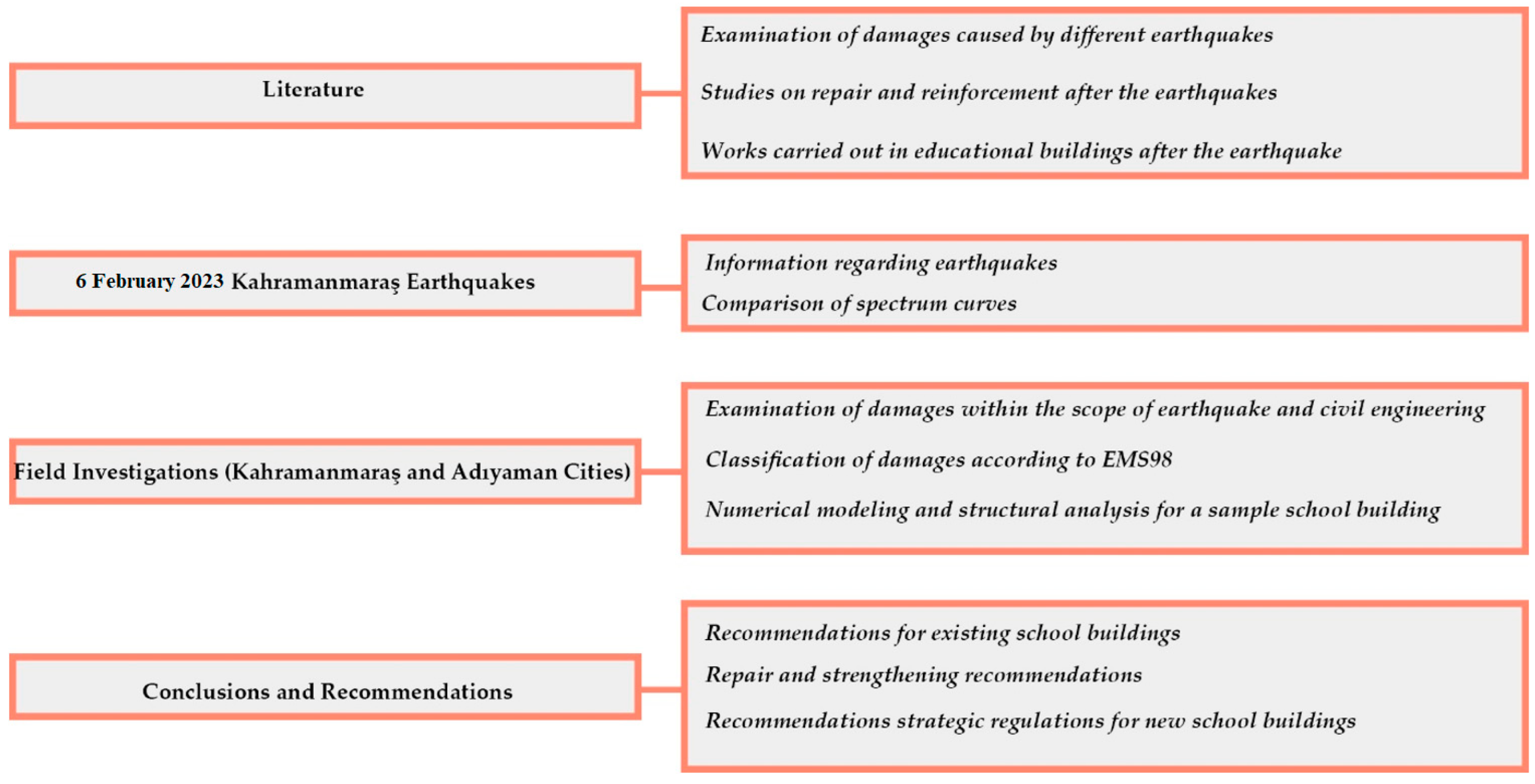
The most significant part that distinguishes this paper from other studies is that this paper focuses only on damage to masonry school buildings after the Kahramanmaraş earthquakes. This study is the first study conducted in this context. Only the masonry educational buildings in the region affected by these major earthquakes were examined in detail for the first time. No study has been found in the literature specifically for such buildings after the February 6 earthquakes. Such school buildings constitute the main goal of this paper due to the risks of loss of life that may occur due to the number of students in such buildings, especially in the event of an earthquake during an hour when education is continuing. The work and processes performed within the scope of this work, i.e., the flow chart of this article, are given in Figure 2.

2. 6 February 2023 Kahramanmaraş Destructive Earthquakes

Türkiye, located in the Alpine-Himalayan seismic zone, has been affected by very large and destructive earthquakes from time to time, and after the last earthquakes, it was once again revealed that it will continue to do so. The major tectonic elements of the country can be listed as the North Anatolian Fault Zone (NAFZ), the Eastern Anatolian Fault Zone (EAFZ), and the Aegean Graben System. As the African/Arabian plates move towards the Eurasian plate, Türkiye is compressed and deformed on the Eastern Anatolian side. The Anatolian plate is also moving towards the West along the KAFZ and EAFZ faults due to compression.
The oldest recorded earthquake in Türkiye occurred in 411 BC. Since instrumental records began in 1900, there have been 20 earthquakes of magnitude 7 or higher. In other words, earthquakes with magnitude 7 and above occur every 6–7 years in Türkiye. However, there have been 269 earthquakes since 1900 that have caused damage and loss of life. Among these, the 6 February 2023 earthquakes rank first in terms of economic loss and loss of life. The intricate process of plate tectonics between the African, Arabian, and Eurasian plates is intimately linked to seismic activity in and around Türkiye. Subduction, continental collision, extension, and escape tectonics are all parts of this complex tectonism. The 6 February 2023 Kahramanmaraş disaster sequence corresponds to the current movement of the fault, which formed approximately 15 million years ago and moves in the northeast direction along the Eastern Anatolian fault system. The Eastern Anatolian Fault System caused many large earthquakes until the early 1900s and showed more seismic activity, especially in the 19th century. The EAF system has produced nearly ten destructive earthquakes, starting with the 1789 Palu earthquake and ending with the 1905 Malatya earthquake. Although the system appeared relatively dormant in the 20th century, it caused several medium-sized earthquakes, including the Bingöl earthquake of 22 May 1971 (M = 6.8) and the 1986 Doğanşehir (M = 5.8 and 5.6) earthquakes. The EAFZ system, which became more active in the 2000s, continued until the earthquakes of 6 February 2023, a devastating earthquake (Mw = 6.3) in Bingöl on 1 May 2003, followed by Karlıova (Bingöl) (Mw = 5.8) on 14 March 2005, (Malatya) (Mw = 5.7) on 21 February 2007, Kovancılar (Elazığ) (Mw = 6.1) on 8 March 2010, Sivrice (Elazığ) (Mw = 6.8) on 24 January 2020, and Karlıova (Bingöl) (Mw = 5.7) on 14 June 2020.
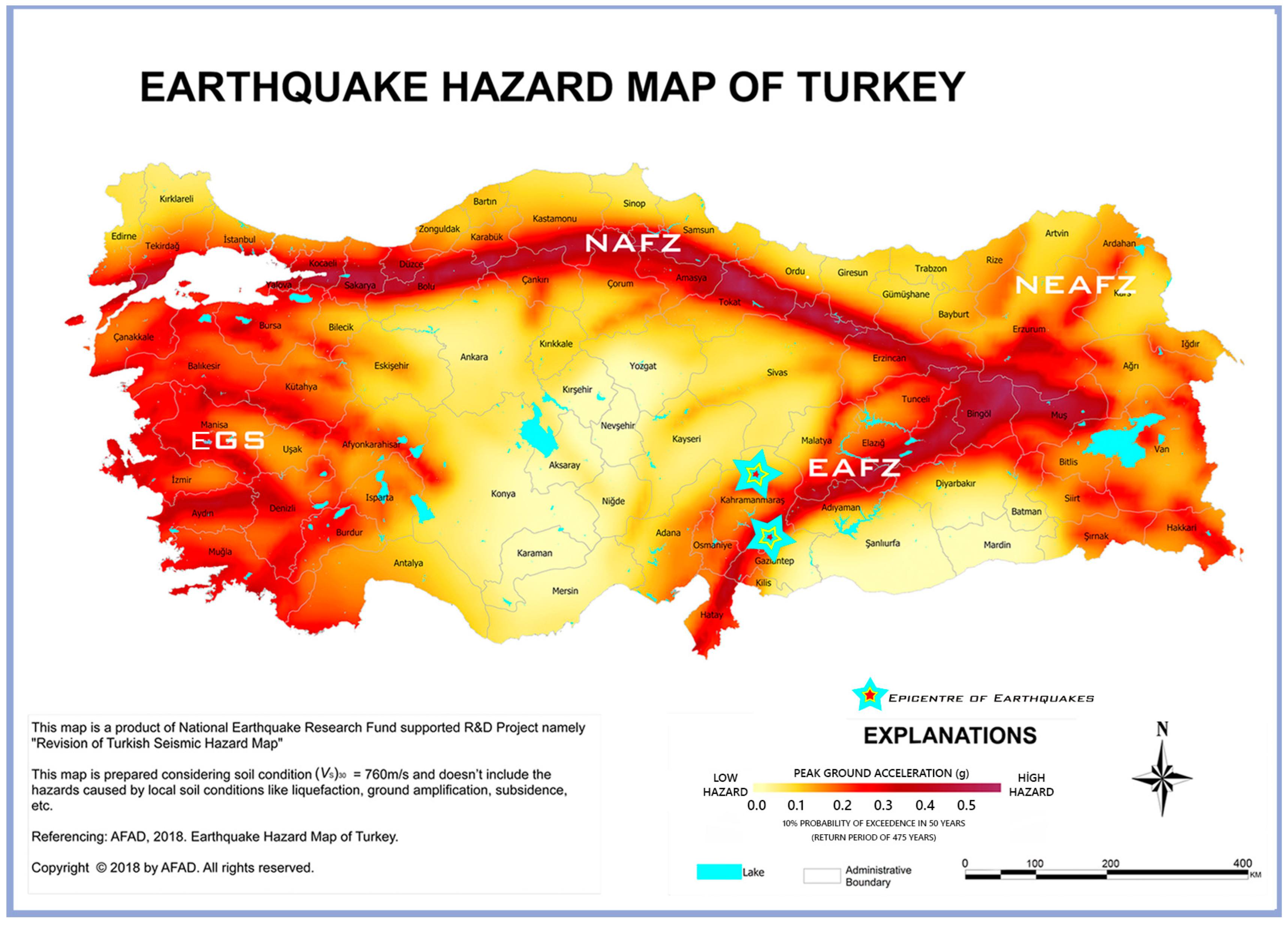
EAFZ, which has had moderate (M < 7) activity since 1905, entered a new activity period that started with the Sivrice (Elazığ) (Mw = 6.8) earthquake on 20 January 2020 and was broken in a large part of the southwestern part of the Eastern Anatolian fault with the February 6 earthquakes. Although the plate movements in this region, which represent complex faulting related to the interactions between the African, Arabian, and Anatolian plates, are low (~10 mm/year), it has been observed that even regions where plate movements are slow can cause extremely damaging earthquakes. The earthquake sequence started in the northernmost part of the Dead Sea fault and caused damage in a wide area by breaking a significant part of the Eastern Anatolian fault. The stress changes that occurred in the crust of the region with the occurrence of the earthquake sequence probably triggered or facilitated additional ruptures in neighboring faults such as the Sürgü fault, which hosted the M 7.5 earthquake and significant aftershocks [48]. The main tectonics of Türkiye are shown in Figure 3.
The 6 February 2023 earthquakes happened in the Pazarcık and Elbistan districts of Kahramanmaraş city, an area where the EAFZ has been silent for approximately 500 years. While the earthquakes caused great loss of life and property in eleven different cities in Türkiye, they were also felt at a significant level in neighboring provinces. The earthquakes also caused loss of life and property in Syria, and more than 5000 people lost their lives. The maximum acceleration values measured in the Kahramanmaraş and Adıyaman provinces for both earthquakes are shown in Table 1.
For the first earthquake, as shown in Figure 4 and Figure 5, the highest value was measured as 2.2 g in the N–S direction in the Kahramanmaraş/Pazarcık (4614) station, which is the epicenter of the earthquake in Kahramanmaraş province, and 0.9 g in the E–W direction in the Adıyaman/Center (0201) station. For the second earthquake, the peak value was measured as 0.65 g in the N–S direction at the Kahramanmaraş/Göksün (4612) station, and as 0.13 g in the E–W direction at the earthquake station in the Tut district of Adıyaman (0213) province. The very high PGA values measured in both earthquakes and the fact that the earthquakes occurred consecutively on the same day greatly increased the destructiveness of the earthquakes. In addition, poor local ground conditions and structural weaknesses had a substantial impact on the destructiveness of the earthquakes.
The response spectrum curves obtained by taking a 2% damping ratio for the 0201 and 0213 stations with the highest acceleration values in Adıyaman province of the two earthquakes with Pazarcık and Elbistan epicenters are given in Figure 6. As seen from the curves, the Spectral acceleration values measured in the earthquake, whose epicenter was Pazarcık, exceeded the DD-1 and DD-2 design ground motion levels, and in the vertical direction, only the DD-2 design ground motion level was exceeded. DD-1 indicates the ground motion level with a repetition period of 2475 years and a 2% probability of exceedance in 50 years. DD-2 indicates the standard ground motion level with a repetition period of 475 years.
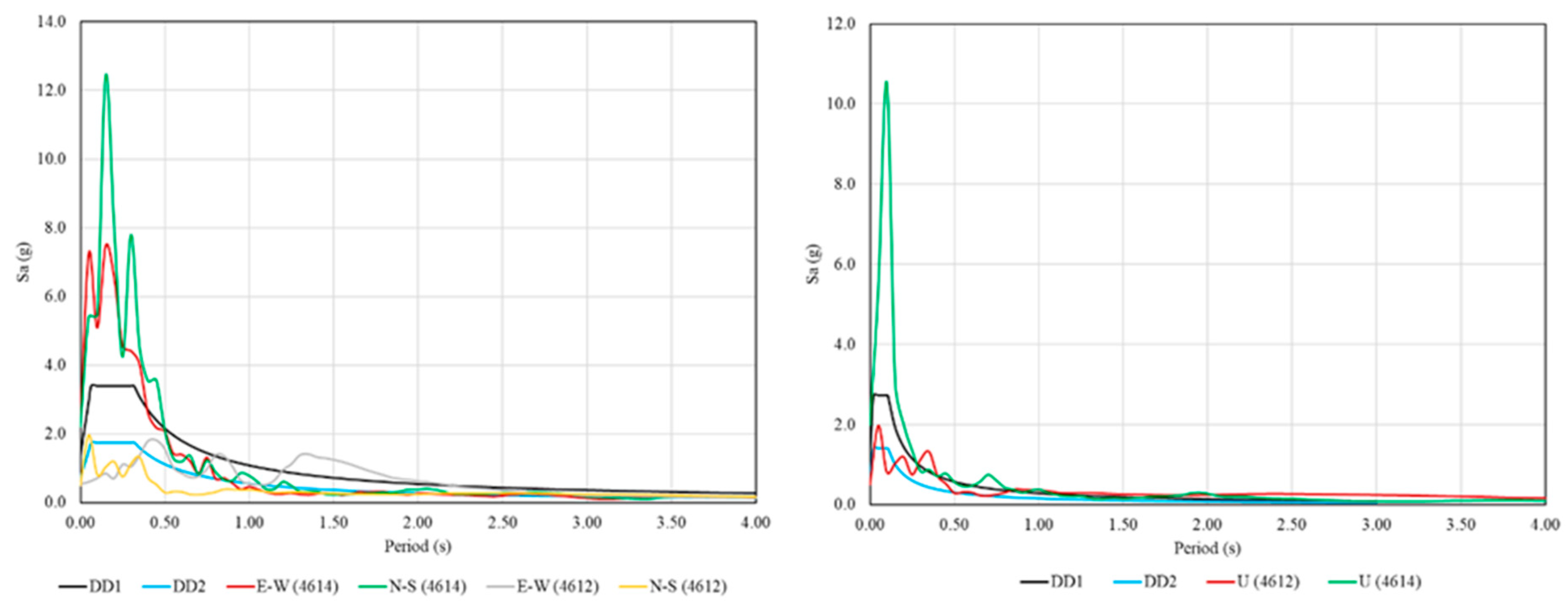
The response spectrum curves obtained by taking a 2% damping ratio for stations 4614 and 4612, which have the highest acceleration values of two separate earthquakes in Kahramanmaraş province, are given in Figure 7. As seen from the curves, in the Pazarcık-centered earthquake, both horizontal and vertical values exceeded the DD-1 and DD-2 design ground motion levels.
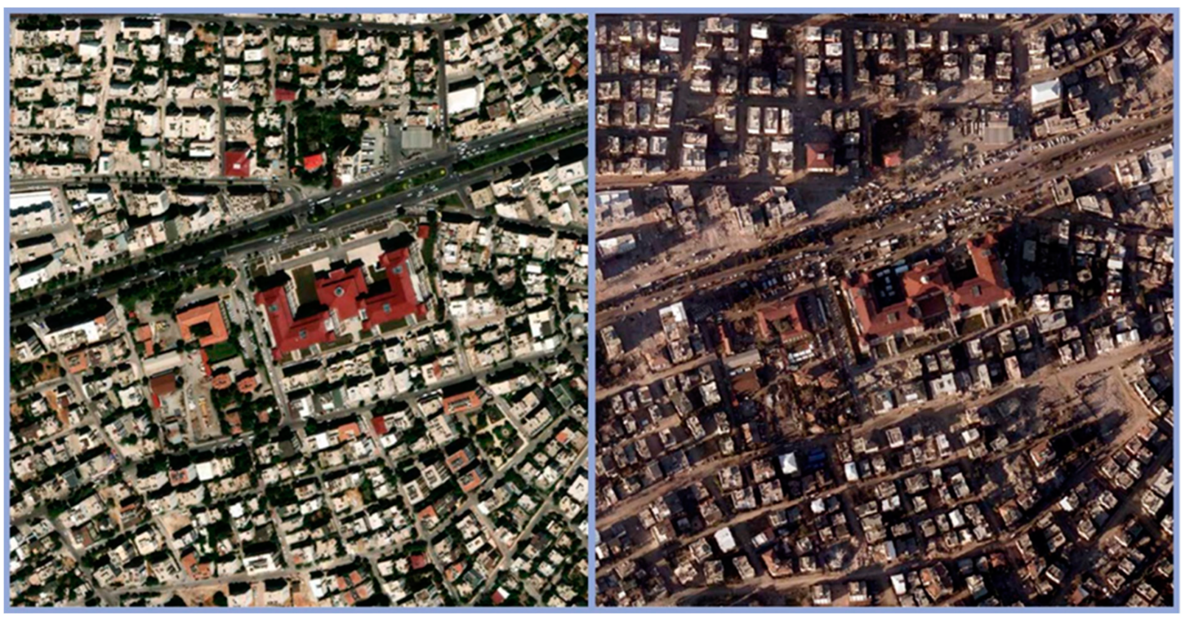
Aerial views before the earthquake and aerial views of the destruction caused by the earthquakes in the Kahramanmaraş and Adıyaman provinces, where more than 350,000 buildings were affected by the earthquake, are shown in Figure 8 and Figure 9, respectively.
After these two earthquakes, the current population, employment, number of affected buildings, and number of damaged buildings of the Kahramanmaraş and Adıyaman provinces and their ratio in the earthquake zone are shown in Table 2.
Due to the earthquakes, which affected 11 provinces at different levels, the buildings in the Kahramanmaraş and Adıyaman provinces that collapsed needed to be urgently demolished, and heavily damaged buildings constituted a total of 30% of the earthquake zone. This ratio clearly indicates that these two provinces were very affected by the earthquake.

3. Educational Buildings in Rural Areas and Observed Damage

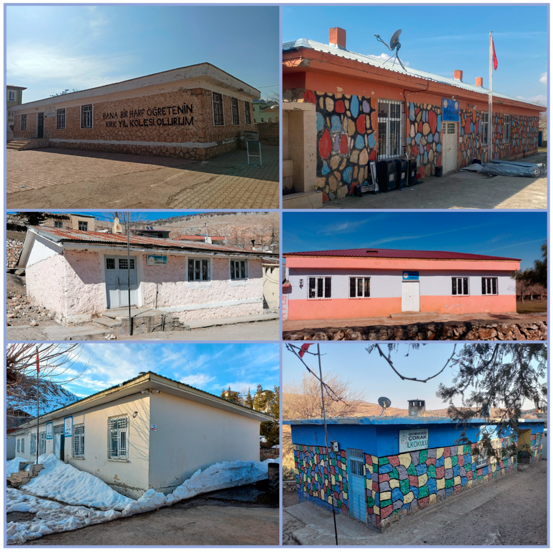
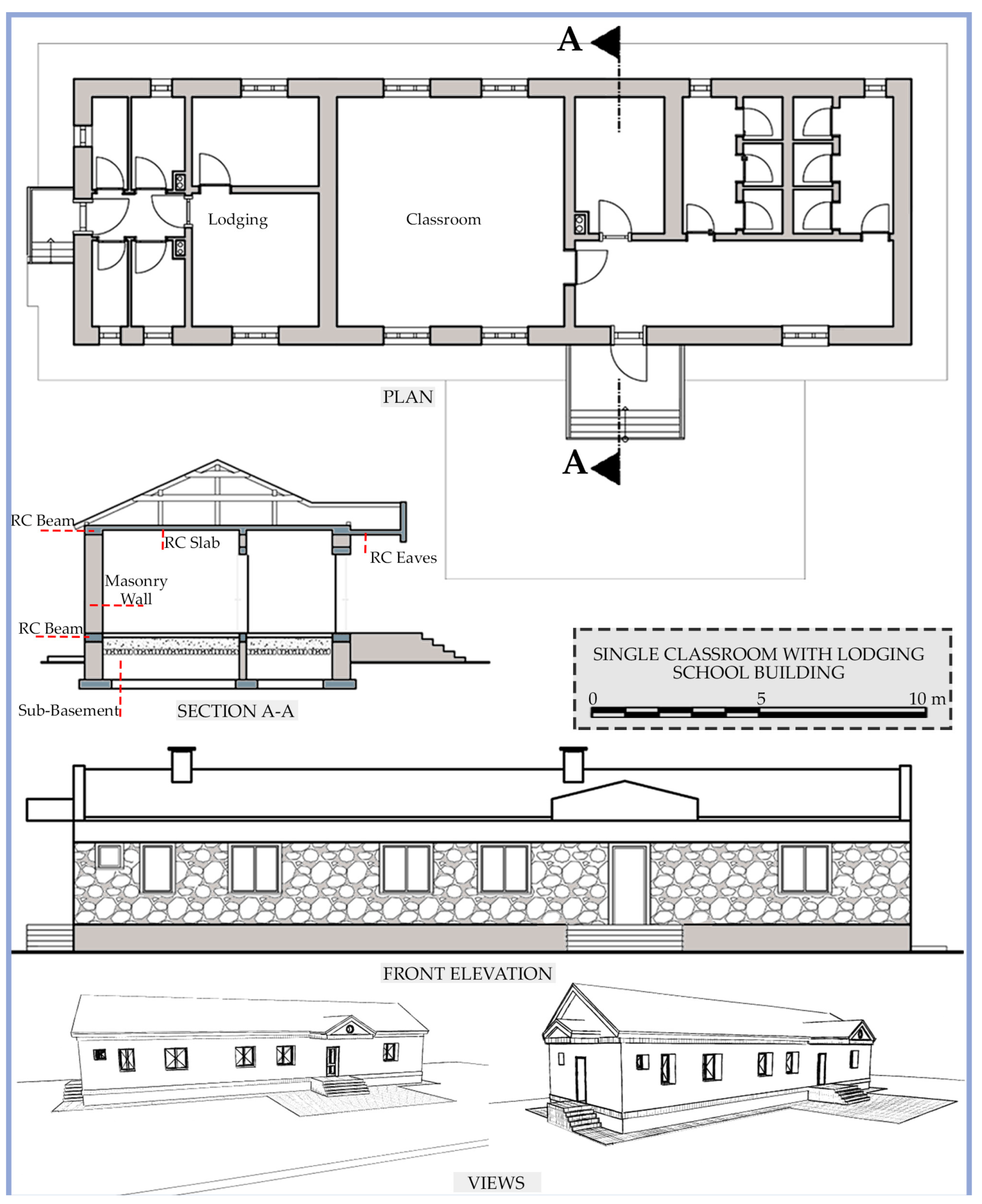
Single-story masonry school buildings with various numbers of classrooms were commonly built in the rural regions of Kahramanmaraş and Adıyaman, which were among the provinces most affected by the disaster. Examples of commonly constructed school buildings are shown in Figure 10.
When constructing masonry school buildings, the sub-basement section is constructed after the excavation of a shallow foundation. In this part, a lower beam is created using concrete, reinforced concrete, or stone to fit under the load-bearing wall. The main purpose of these elements is to transfer the loads on the load-bearing walls to the ground more easily. Additionally, there is a reinforced concrete bond beam on all building facades, just above the sub-basement. Bearing walls are built on the bond beam by combining different wall materials with cement mortar. Beams made of reinforced concrete are used on these masonry walls. The structure is completed by using reinforced concrete slabs on the beams. Depending on the climatic conditions, a roof can be used over the flooring. As a result of the observations made in the region, some school buildings use parapets on the four sides of the building on reinforced concrete floors, and there is no roof in such buildings. There are no reinforced concrete columns or enclosure systems in these buildings, and only the walls serve as vertical components. An example view of these schools is shown in Figure 11.
School buildings of different typologies are shown in Figure 12. Variations in the number of classrooms, the wall material used, and the roof shape can be considered as variables seen in such buildings.
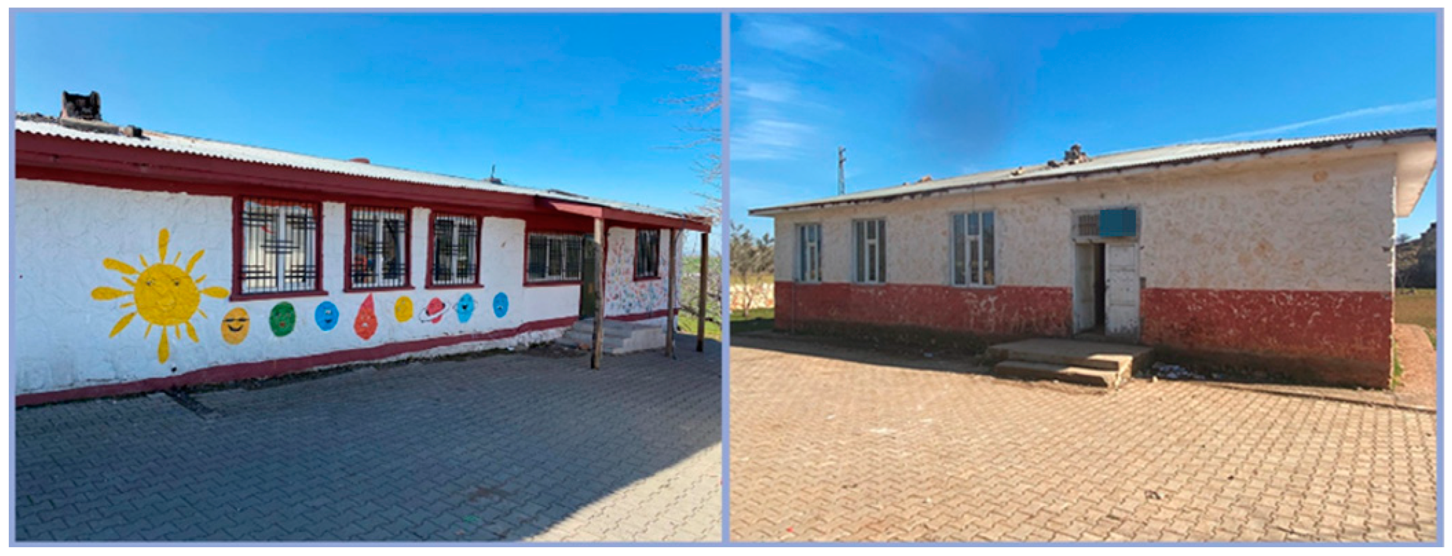
In these masonry school buildings, the load-bearing wall materials have high compressive strength and very low tensile strength identical to other types of masonry structures. While these walls can show sufficient strength under the influence of large pressure forces, they cannot show sufficient resistance against bending and shear forces. These components are susceptible to bending and shear stresses in this situation since they may be subjected to high-pressure forces [53,54,55,56,57,58] Damage levels in masonry structures may vary due to the large pressure forces that occur based on the magnitude of the earthquake. Examples of single-story schools that were built in rural areas affected by the Kahramanmaraş earthquakes and were not damaged at all are shown in Figure 13.
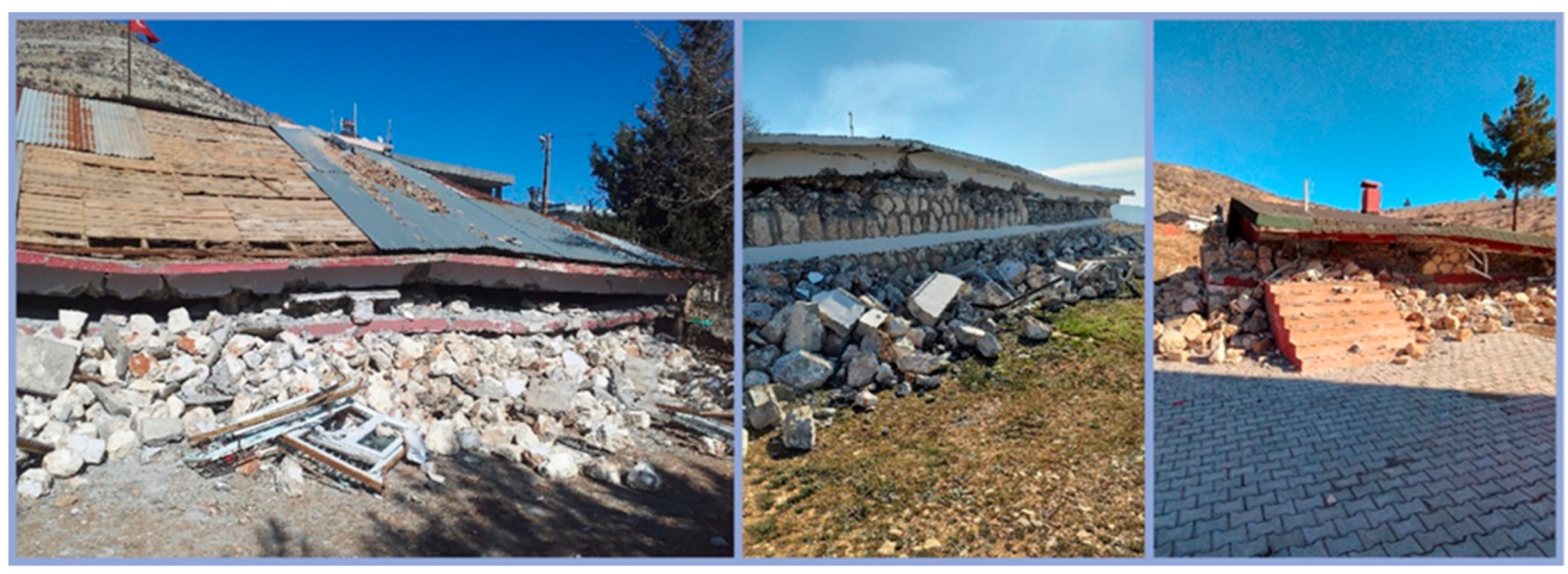
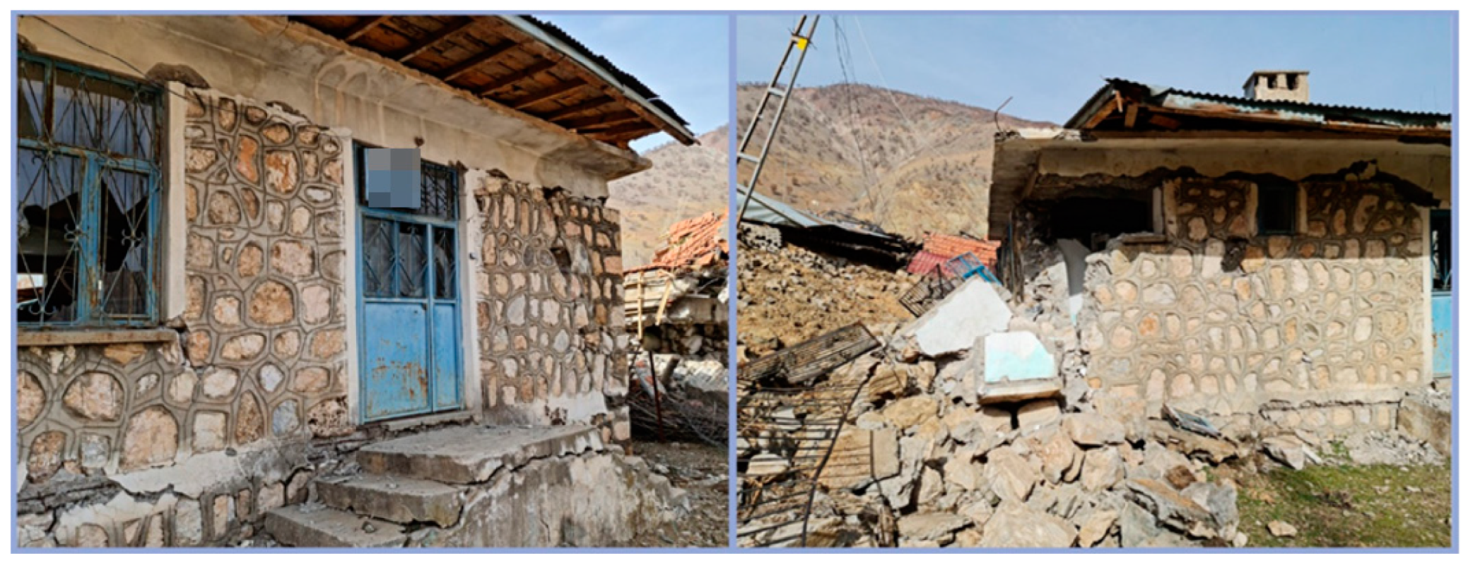
Near the epicenter of the earthquake, most of the masonry buildings had either completely collapsed or suffered significant damage. The poor load-bearing walls were the main cause of this. In general, neither the unsupported wall length nor the necessary window openings, the length between corners and the closest doors or windows, or the apertures between windows and doors were met by the load-bearing walls of the masonry structures. Examples of school buildings that collapsed completely and became rubble due to the effect of the earthquakes are shown in Figure 14.
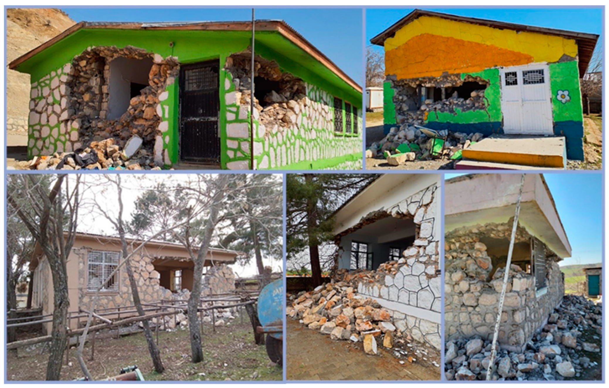
Examples of school buildings that did not collapse as a result of the first earthquake, but a large part of the building was exposed to collapse after the second major earthquake and the subsequent aftershocks, are shown in Figure 15.
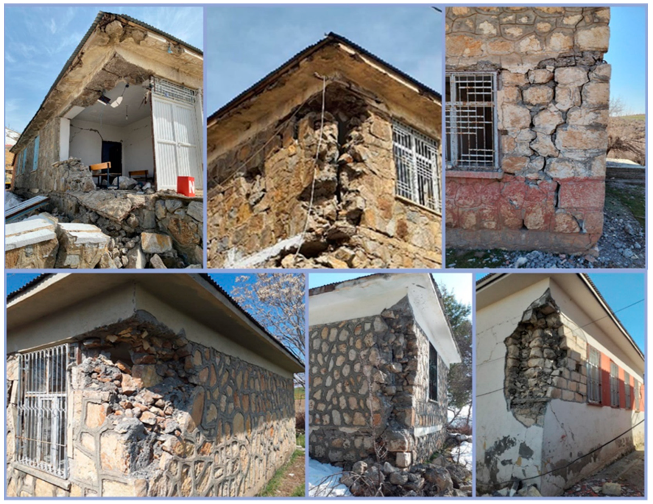
In the formation of the corners of masonry structures, the lack of connection between load-bearing walls in this region causes them to show weak behavior under earthquake loads. This mechanism is usually caused by the absence of a diaphragm provided by the cornerstones that provide adequate connection, preventing wall separation and out-of-plane failure [59]. Examples of such damage occurring at the corners are shown in Figure 16.
Since masonry structures are not homogeneous and monolithic and have negligible tensile strength and high weight, early local damage mechanisms often occur during earthquakes. Due to the low load-bearing wall material strength, wall thicknesses are much greater than reinforced concrete structures. By combining different layers to ensure thickness, more load is provided by increasing the cross-sectional areas of the walls. However, failure to ensure adequate interlocking between layers prevents these layers from working together, especially under earthquake loads. Examples of damage resulting from insufficient interlocking between layers are shown in Figure 17. In order to achieve greater thickness, structural walls consist of different layers. While the layers are created from the same material, they can sometimes be constructed from different types of materials. In general, while better materials are used on the outside, relatively worse materials are used on the inside. In particular, not creating sufficient connections between layers causes separation between layers. In addition, in walls built using materials with different properties, the different strength properties of the materials directly affect their earthquake performance.
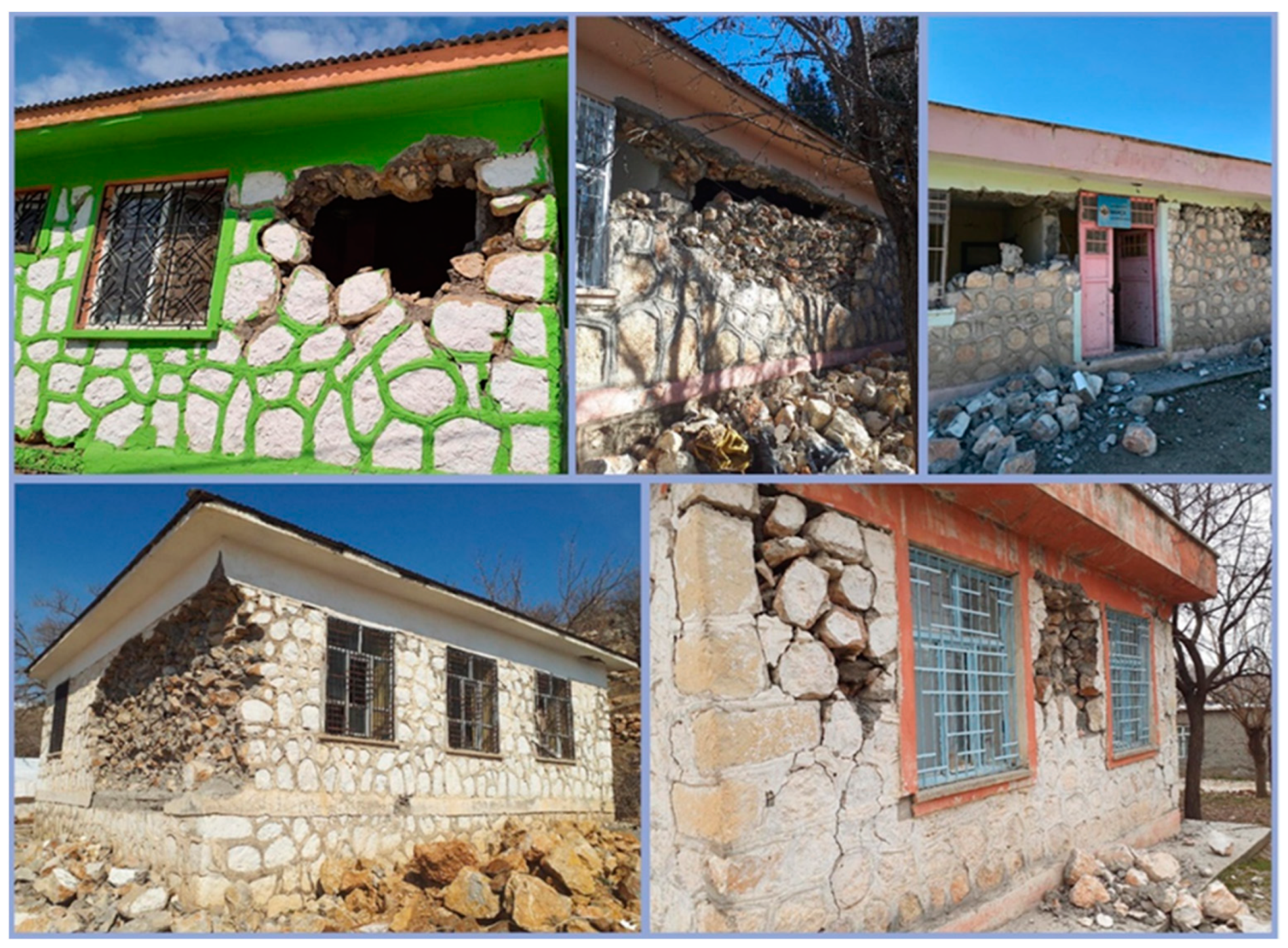
One of the commonly observed damages on load-bearing walls, which are used in masonry structures to both protect the structure from external forces and to divide the spaces, is the damage that occurs as a result of these walls being subjected to out-of-plan failure mechanisms. Examples of out-of-plane failure mechanism damage are shown in Figure 18.
The use of low-strength mortar in the creation of load-bearing walls, poor masonry work, and random use of wall materials have caused different levels of damage to the load-bearing walls. Examples of failure resulting from these situations are shown in Figure 19.
Some structures had no damage during the earthquake or survived with slight damage, but non-bearing structural elements such as chimneys suffered different levels of damage. Examples of collapsed chimneys are shown in Figure 20.
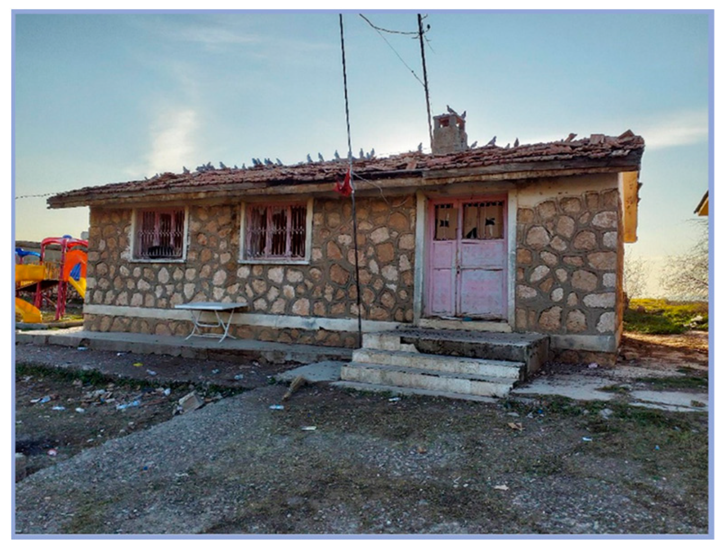
Figure 21 shows a masonry school building with an improper roof connection. It can be seen that the roof, which was disconnected from the structure due to the effect of the earthquake loads, had a horizontal displacement of more than 1 m and the structure was severely damaged.
Although it is not widely used in the region, the use of tiles on roofs has been observed in settlements where climatic conditions are suitable. The roof tiles of some masonry school buildings, which were slightly damaged during the earthquake, were separated and the roof was damaged. An example of damage to this type of roof is shown in Figure 22.
Cracks that do not cause a decrease in the bearing capacity of the load-bearing walls are one of the other types of failure noticed in such structures in the earthquake zone. Examples of cracks that do not affect the earthquake performance of the buildings are shown in Figure 23.
In some buildings, damage was also observed in the reinforced concrete bond beams used in the sub-basement section and just above the sub-basement section. Examples of the damage to these structures, most of which have minor damage, are shown in Figure 24.
The use of wall materials with various strength characteristics in the construction of load-bearing walls also caused damage due to the different behavior of each material under earthquake loads. Examples of damage caused by using different wall materials together are shown in Figure 25.
The lack of a connection between the reinforced concrete beam used to form the roof and the load-bearing wall, i.e., insufficient interlocking, also caused separation damage between the RC beam and the wall. Examples of such damage are shown in Figure 26.
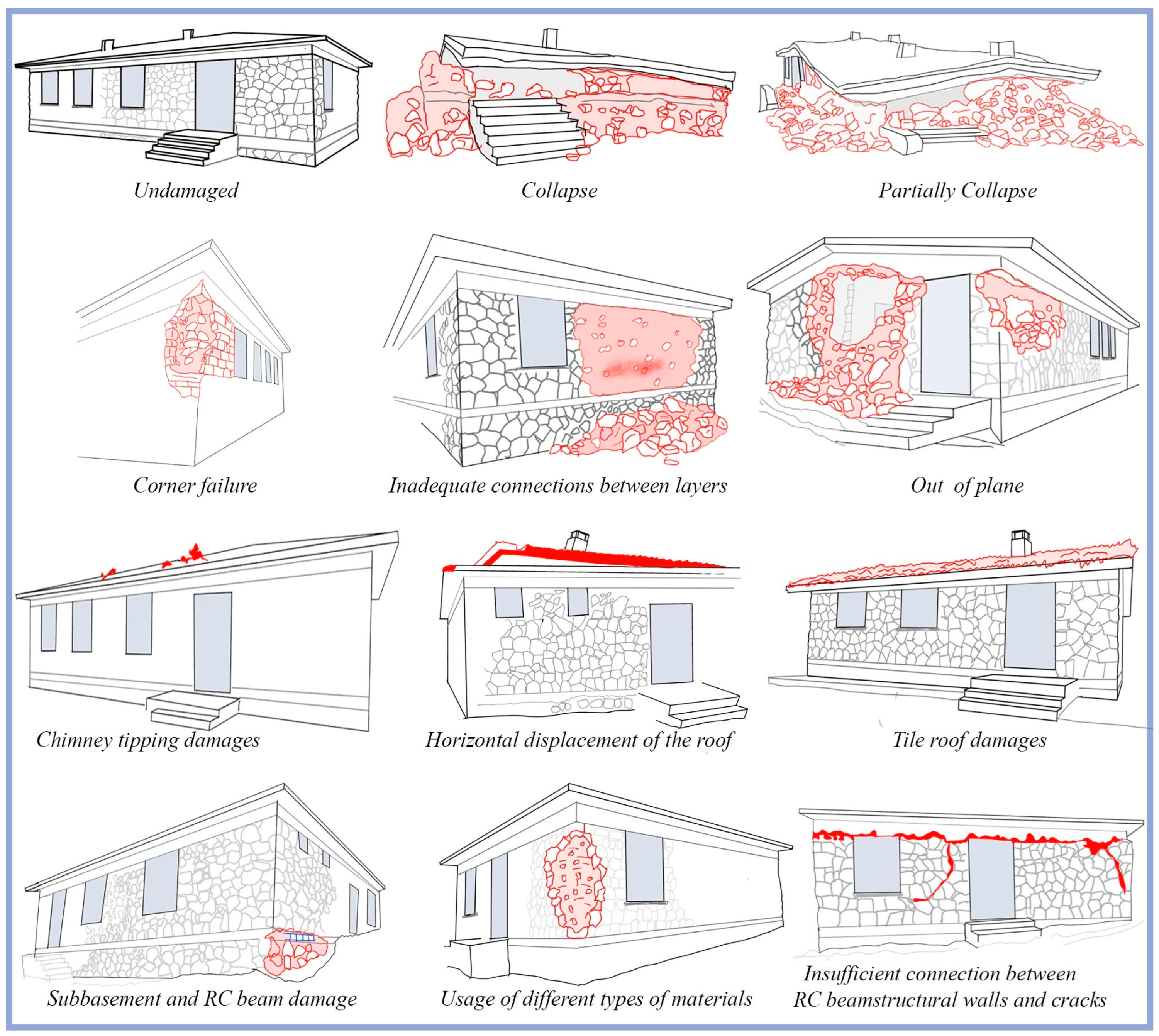
The damage observed in masonry school buildings as a result of field observations made by the authors in the disaster region is clarified in detail. The schematic representation of the structural damage as a consequence of the field investigations is given in Figure 27. The red colors show the damage and cracks of the buildings.

4. Classification of the Damage in Educational Buildings in the Earthquake Region

The destruction of the completed environment is one of the biggest effects of the earthquake. These effects can be classified as loss of life and property, structural damage, and economic losses resulting from these. The effect of the earthquake on structures is called structural damage, and different levels of grading damage can be predicted. By using structural damage data, information about the effects and severity of the earthquake can be obtained. Within the scope of this study, the effects of the Kahramanmaraş earthquakes, which caused significant structural damage in eleven different provinces, on masonry structures were examined observationally. As a result of on-site observational examinations for each building, an attempt was made to establish the cause-and-effect relationship of damage. In general, the damage that occurred is similar to the damage that occurred in previous earthquakes.
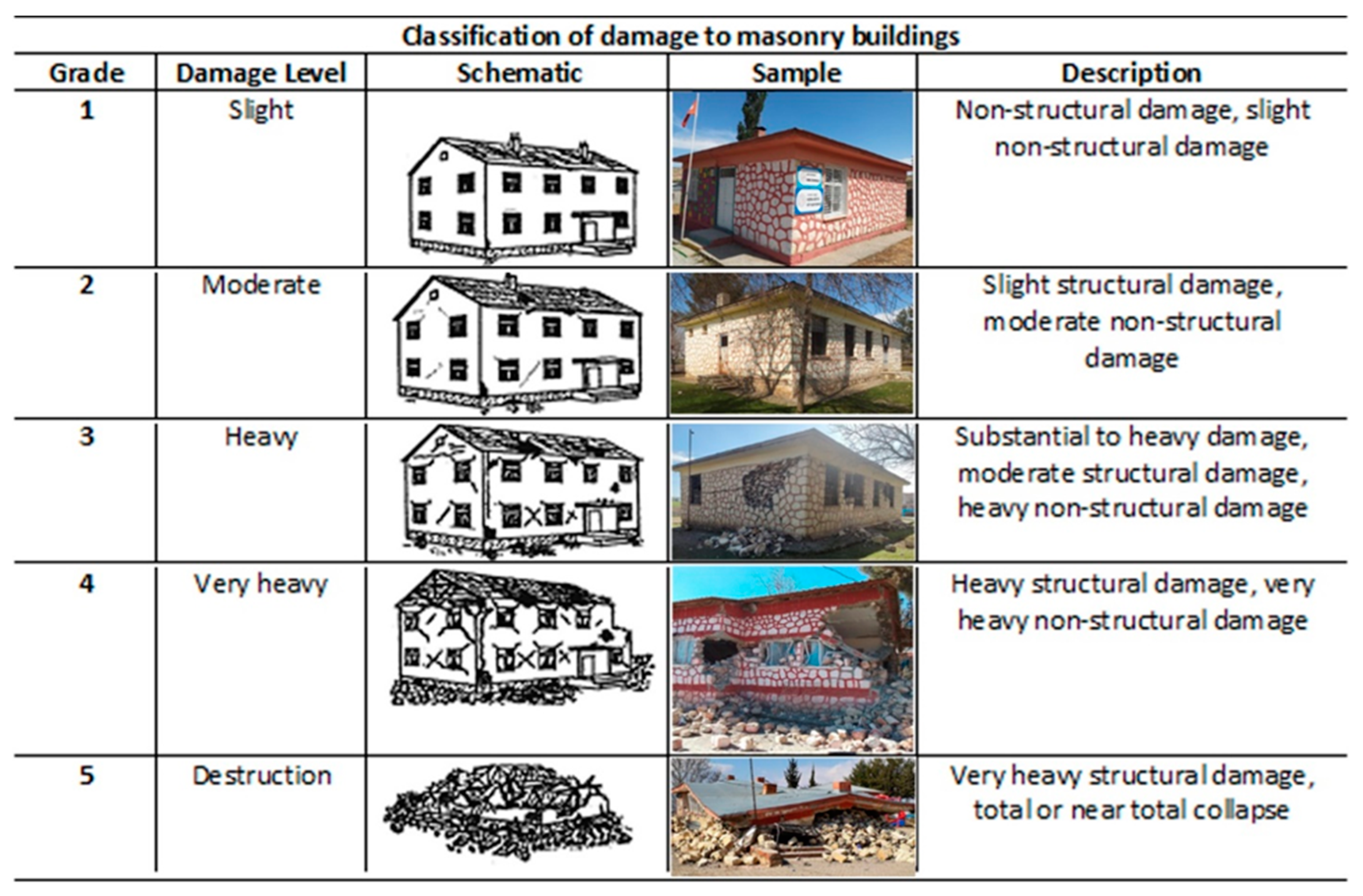
Furthermore, in earthquake-prone areas, building damage information is crucial for search and rescue, humanitarian relief, and restoration efforts. Damage scales can be used in the field to assess building damage [60]. The masonry constructions under investigation in this study were subjected to damage grading using EMS-98. The European Commission of Seismology (ESC) designed the European Macro-Seismic Scale (EMS-98) with extensive damage levels in mind [61,62,63]. Figure 28 displays the damage grading of masonry structures in EMS-98. The studied structures were all classified as vulnerability class A since they are all made of adobe.
The classification of damage levels for the 124 masonry school buildings is shown in Table 3.

5. Structural Analysis for the Reference School Building

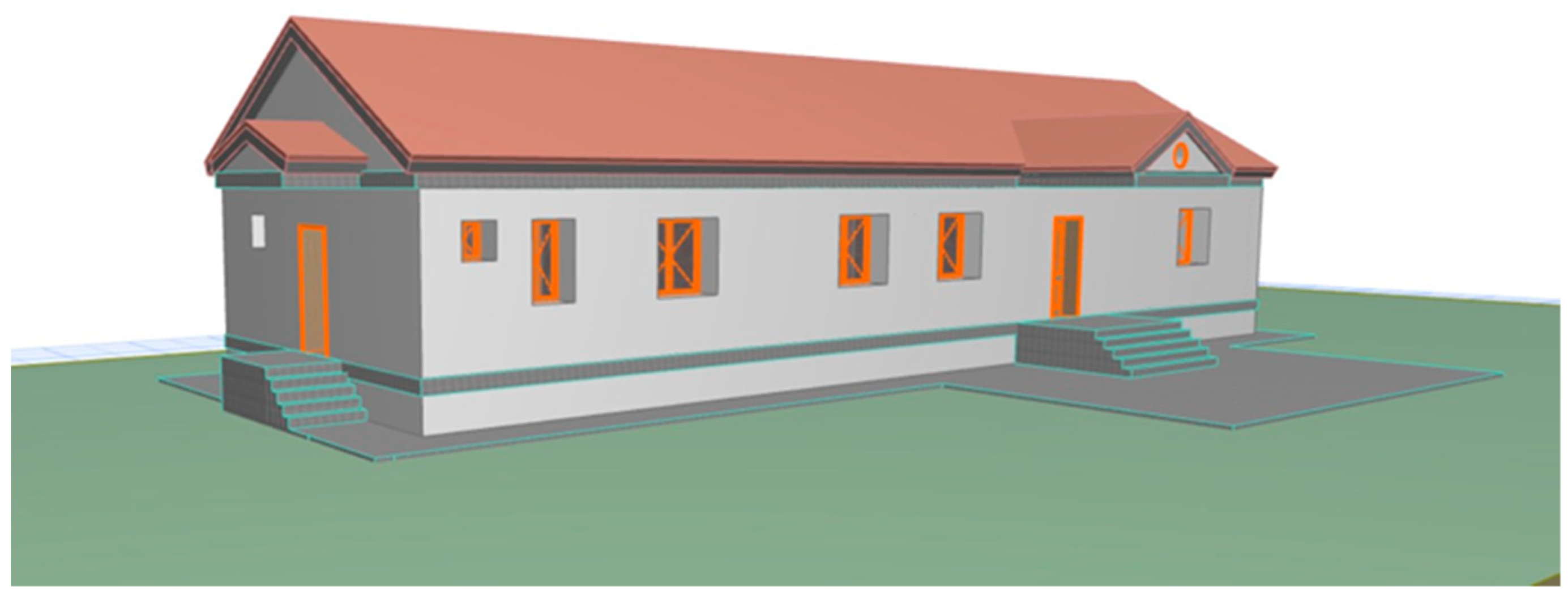
The selected school was constructed and situated within the city of Kahramanmaraş. Figure 29 provides an overview of the selected school building. The reference building has a rectangular plan of 7.40 and 23.32 m in width and length and is 3 m high. The outer wall thickness is 0.5 m and the inner wall thickness is 0.3–0.5 m.
The primary dimensions of the school building’s load-bearing system were determined through on-site investigations and then compared with the architectural blueprints. The analysis was conducted in accordance with the identified load-bearing system dimensions. Due to the age of the buildings under examination, there were very few architectural drawings or information about the original state of the structures. As a result, a comprehensive examination of the current buildings was conducted. In these projects, the positions and sizes of doors, windows, and walls were established. The measurements were used to create structural floor plans for the current building, and TREMURI Software was used to create the matching structural models for seismic analysis [64].

5.1. Estimation of the Seismic Capacity of the Building

When modeling the selected building, two key considerations must be taken into account: making certain that the mathematical model is accurately represented and taking into account the inelastic properties of materials. Unreinforced Masonry (URM) serves as a composite building material, consisting of mortar and masonry units. Typically, masonry units involve bricks and stones, with mortar serving to connect these units. The load-bearing capacity of masonry, viewed as the assembly of mortar and masonry units under both horizontal and vertical forces, is affected by factors such as compressive, shear, and flexural strengths, as well as thermal expansion, water absorption, and considerations of durability.
Describing the properties of masonry walls in existing structures is a complicated task. In this paper, mechanical properties were determined through the analysis of building regulations, blueprints, and structures constructed during corresponding periods. In situations where experimental data are insufficient, various equations provided by different codes and guidelines are employed to estimate the compressive strength of the masonry walls. The guidelines found in Eurocode [65] were employed for this investigation.
Modeling masonry structures is challenging because of the nonlinear behavior of masonry and the limited availability of experimental studies on the inherent properties of masonry structural members. In order to obtain the essential geometry and structural information, on-site studies were carried out. On-site studies were performed to obtain the necessary geometry and structural details.
Masonry, a heterogeneous material made up of mortar, masonry bricks, and stones, displays mechanical qualities based on the characteristics of its constituent parts. Its behavior under various loadings can be highly complex. Many presumptions and analytical models that have been put out in the literature, such as [66], are employed to model the response of masonry. Each technique necessitates the adoption of different constitutive models.
A macro-modeling technique was used in this work because of the sophistication of the case study building, different material property assumptions, and the need for high-performance computers to run nonlinear analysis. Pushover analysis was conducted using TREMURI software, a versatile finite element program dedicated to the linear and nonlinear analysis of masonry structures. Pushover analysis using TREMURI software was used to evaluate the seismic load-bearing capacity of the school building block, which was analytically modeled (Figure 30).
Using a convenient damage indicator that may express seismic performance with suitable damage limits, damage limit states function as mathematical definitions of performance levels. Quantitative measures of structural behavior, including displacements and deformation quantities, should be used to describe these states. Damage limit states were defined in this study based on the suggestions made in Eurocode 8 [67].
Eurocode 8 [67] is used in the assessment of the researched buildings’ capacities. The research takes into account three degrees of damage limit states: “Limited Damage” (LD), “Significant Damage” (SD), and “Near Collapse” (NC).

5.2. Seismic Analysis for the Existing Case

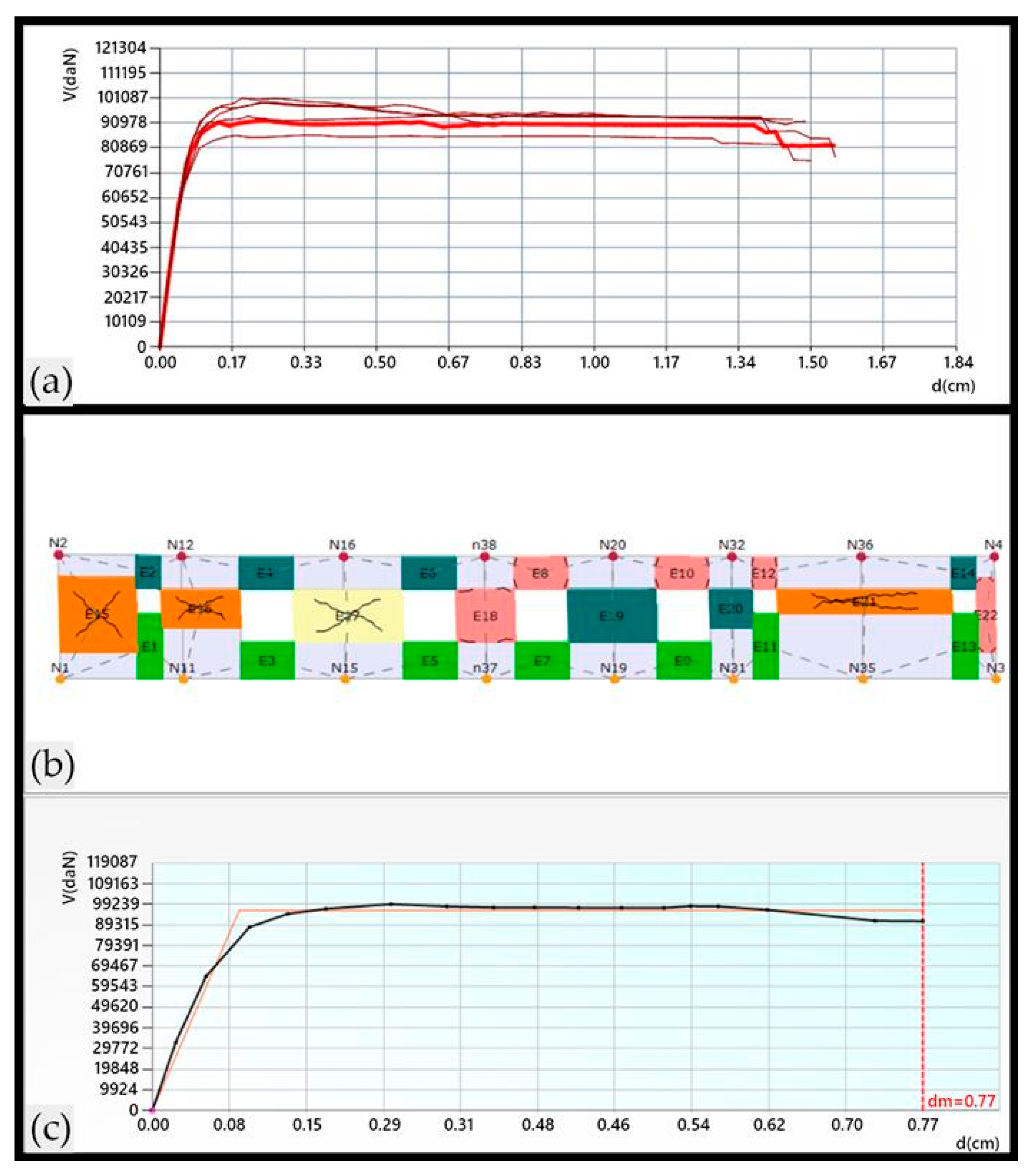
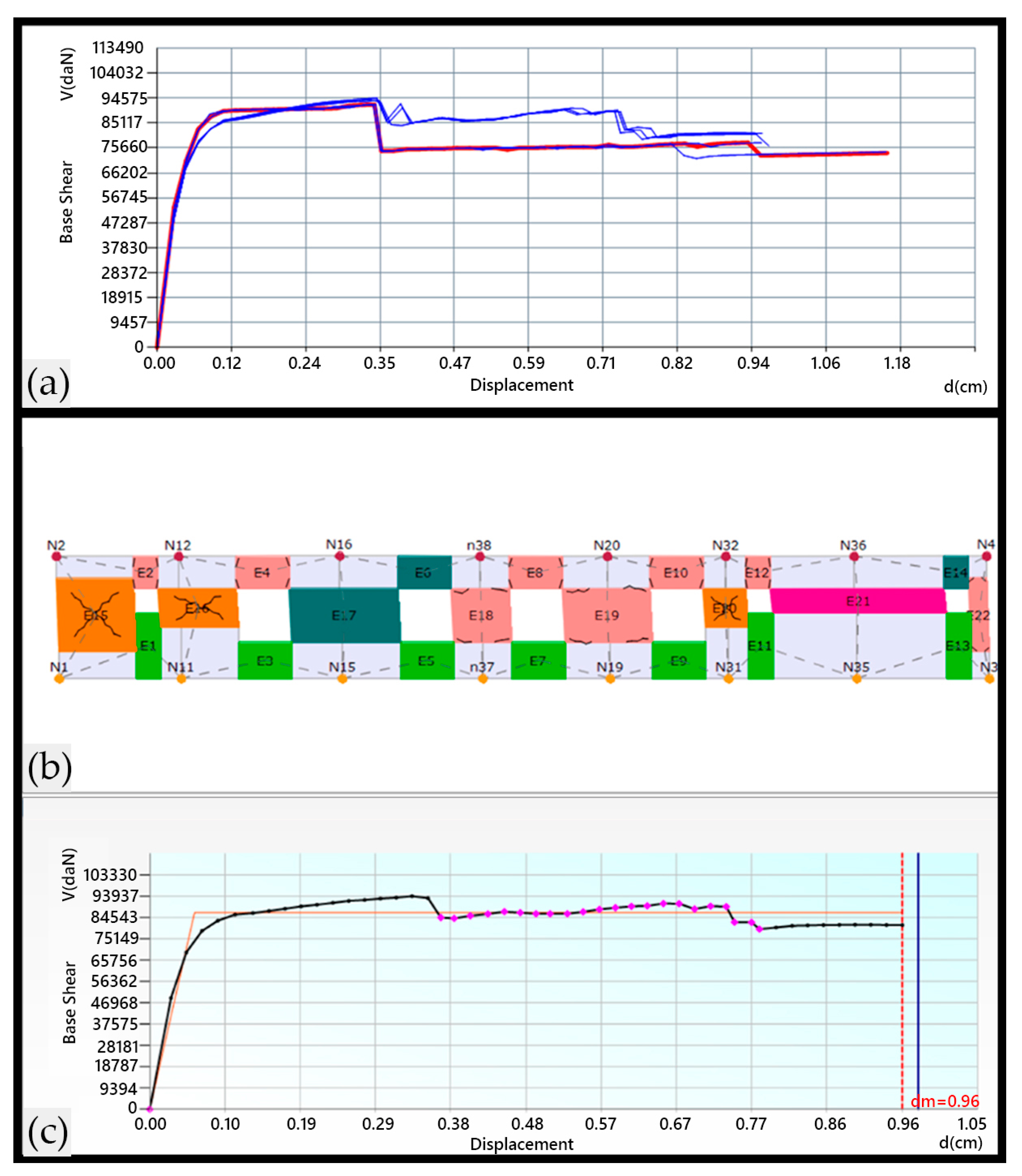
In the TREMURI software package, two types of load patterns are utilized: one that is proportional to the distribution of the structure’s first mode shape (static), which is based on the fundamental mode shape of the structure, and another involving a uniform load distribution across all stories. These load patterns are applied separately in both the X and Y directions, with both positive and negative values, resulting in a total of eight analyses: +x MF1, +x uniform, −x MF1, −x uniform, +y MF1, +y uniform, −y MF1, and −y uniform. Each of these analyses is conducted for every combination, with and without the eccentricity of gravity loads at two different levels. Thus, a total of 24 analyses are performed for both red clay and silicate brick buildings, considering all load combinations, earthquake directions, and eccentricity scenarios. The most critical scenarios from these analyses are selected to represent the pushover curves for both the X and Y directions of the buildings, as shown in Figure 31a and Figure 32a.
Figure 31b and Figure 32b display a detailed distribution of damage along the height of the walls within the analyzed building. The building experiences failure when the perimeter walls reach their load-bearing capacity in both orthogonal directions. Specifically, failure occurs when the right portion of the perimeter wall fails due to bending stress, along with the wall at the rear portion on upper levels.
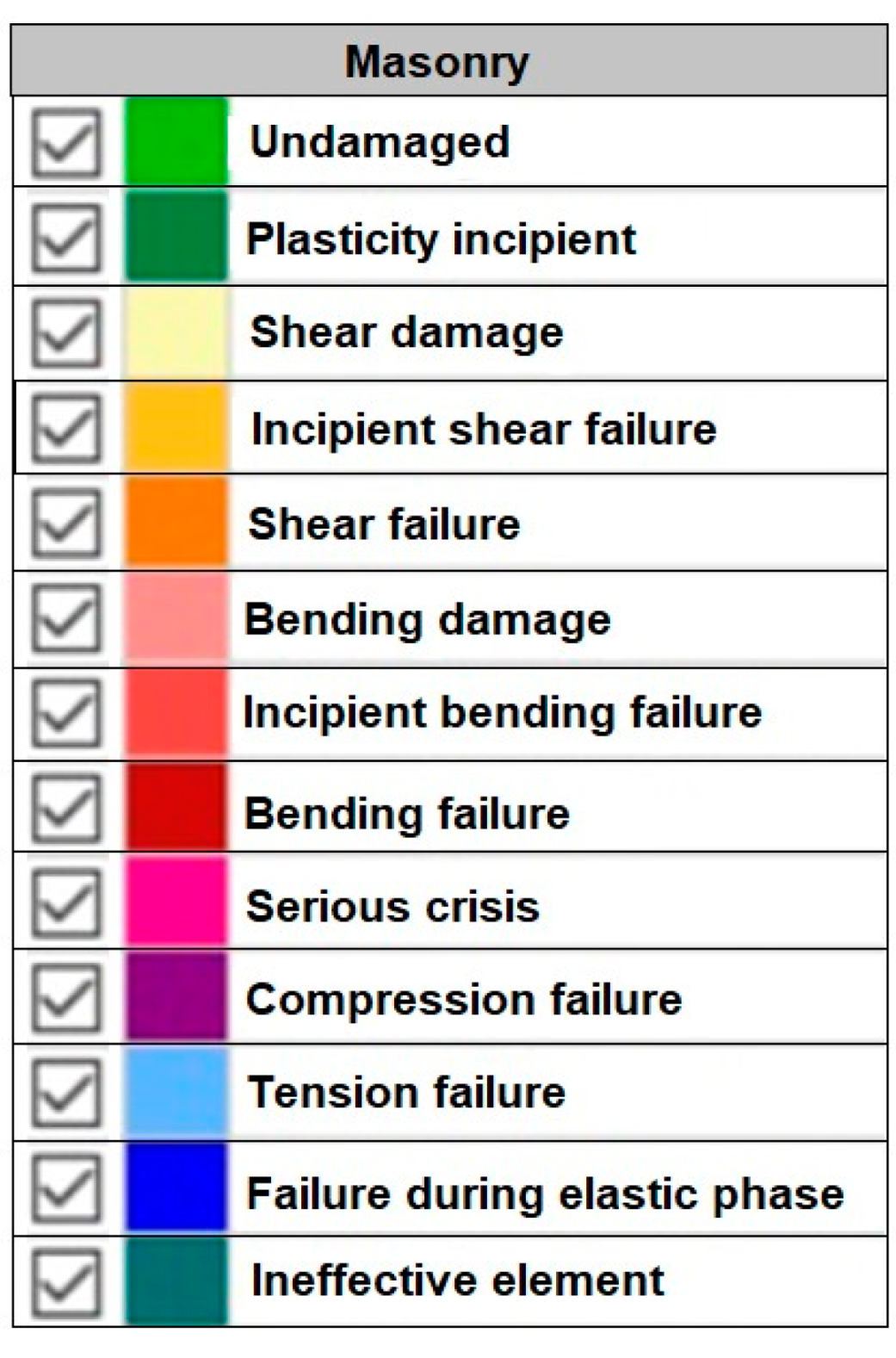
The legend for Figure 31 and Figure 32 is shown in Figure 33.
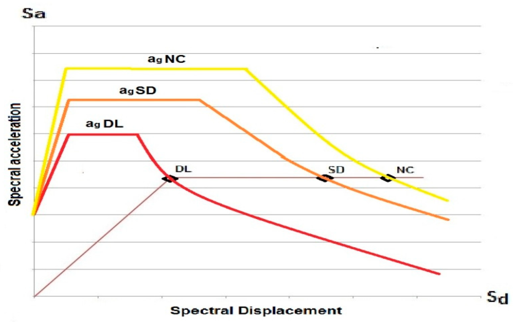
The drift ratio is the primary parameter used to define performance points. The limit states are calculated and compared with the EC spectrum using the equivalent displacement method to determine if the limit state is exceeded by the given ag value. This process is repeated for different ag levels for all three limit states: DL, SD, and NC. Throughout this procedure, all spectrum parameters, except ag, remain constant (including soil conditions and periods). Capacity versus demand analysis (determination of the performance point) is repeated until the limit state is reached and exceeded. The resulting value is the maximum ag that the limit state can endure. This analysis was conducted using the 3muri software. The simplified procedure is given in Figure 34.
Table 4 outlines the peak ground acceleration (PGA) limits that buildings can withstand for various damage limit states, as per the guidelines of Eurocode 8 [67].
The material properties of the chosen building were determined from the reference values of the mechanical parameters and the average specific weight of the different masonry typologies to be adopted for seismic risk assessment [68].
In the absence of experimental data, various codes and guidelines offer multiple equations to estimate the compressive strength of masonry walls. This study follows the guidelines presented in Eurocode 6 [69], as outlined below:
fk = K × fb0.70 × fm0.30 (MPa)
where fb is the normalized mean compressive strength of masonry units; fm is the mean compressive strength of mortar; and K is an empirical coefficient depending on the classification of masonry units.
According to Lourenço et al. [70], the tensile strength is generally considered to be 5% of the compressive strength. To determine the normalized compressive strength of masonry units, the mean compressive strength of the tested units is multiplied by the δ factor, as outlined in Eurocode 6 [69]. When experimental data are not available, Eurocode 6 [69] suggests using a Young’s Modulus value of E = 1000 fk (MPa). The fracture energy is calculated using Equation (2), as described by Lourenço et al. [70].
Gf = 0.025 × (2 × ft)0.7 (MPa)
where Gf is the tensile fracture energy and ft represents the tensile strength.
In accordance with the directives provided by Eurocode 6 [69], the relevant material properties were used to compute the necessary input parameters for the analytical modeling of the examined building. These values were then adopted for the subsequent analyses.
Damage limit states are defined by mathematical expressions of performance levels, utilizing a practical damage indicator to effectively represent seismic performance through appropriate damage thresholds. Various damage limit states have been proposed in the literature, including works by Tomazevic et al. [71] and Costa et al. [72]. For this study, the definition of damage limit states followed the specifications outlined in Eurocode 8.
The assessment of seismic capacity is conducted in accordance with Eurocode 8. This involves examining three distinct levels of damage limit states: “Damage Limitation” (DL), “Significant Damage” (SD), and “Near Collapse” (NC). Notably, Eurocode 8, Part 3 specifically addresses the seismic assessment of existing buildings, in contrast to Eurocode 8, Part 1, which is focused on newly designed structures. Additionally, Part 3 provides estimates for the drift capacities of unreinforced masonry (URM) piers.
Regarding the “Limited Damage” state, it is crucial that the strength and stiffness of the unreinforced masonry (URM) structure remain substantially intact, with any permanent drifts being negligible, as outlined by Eurocode 8, Part 3. The “yield” drift, denoted as θy, marks the intersection of the elastic range with the pier’s strength, defining the rotational limit state referred to as “Limited Damage” (θLD). The second limit state, termed “Significant Damage”, is critically important in seismic structure assessment, especially for a seismic action return period of 475 years. Eurocode 8 provides guidelines for the drift capacities of masonry piers, taking into account factors such as the failure mode (shear or flexure) and the shear aspect ratio H0/L. Here, H0 represents the height at which the moment is zero, while L denotes the length of the pier wall.
Pier Shear failure: δSD = 0.4%
Pier Flexural failure: δSD = 0.80% (H0/L)
Equations (3) and (4) provide the drift capacities for the “Significant Damage” (SD) limit state. To calculate the drift capacity for the “Near Collapse” (NC) limit state, the values given in Equations (1) and (2) are adjusted by a factor of 4/3, as specified in EN 1998-1 [73]. This approach is also utilized in other design codes, as illustrated by Kržan et al. [68].
In the context of an entire structure, Eurocode 8 defines the “Near Collapse” (NC) limit state in terms of “roof displacement”, where the total base shear drops below 80% of the structure’s peak resistance. This decrease is due to the progressive damage and failure of lateral load-resisting components. For individual structural elements such as piers or spandrels, Eurocode 8 does not provide a quantitative measure of the strength reduction at the “NC” limit state. Instead, it qualitatively indicates that while piers may have significantly lost their lateral strength and stiffness, they should still be able to transfer vertical loads to the foundation.
The seismic capacity of the school structure is relatively limited in both directions due to the low quality of materials and, consequently, insufficient stiffness, especially when compared to similar structures of this type. Damage to the school building sustained by the 6 February 2023 earthquake is confirmed by pushover analysis results and damage inspection findings.

5.3. Seismic Retrofitting Methodology

Buildings damaged by earthquakes undergo a protracted retrofitting and renovation process after their initial evaluation. Improving the seismic resilience of current buildings is crucial to enhance their performance in the event of future earthquakes. Structure strength can be increased by using traditional strengthening methods such as grouting or reinforced concrete jacketing [74,75,76]. Furthermore, research on the application of FRP for strengthening a wide range of different material-based structures has been carried out throughout the years [77,78,79,80,81]. The authors of ref. [82] performed two tests on unreinforced and retrofitted masonry walls. In the first test, one side of the wall received shotcrete and reinforcement, while in the second, the panel’s two sides received an equal distribution of reinforcing mesh. The lateral force was given in increasing steps throughout testing until the wall failed. The walls’ ultimate lateral load resistance was raised in both retrofit tests by a factor of roughly 3.6. The surface treatment resulted in a three-fold increase in stiffness at peak loading, whereas the starting stiffness remained unchanged. Moreover, it can be said that the final load-carrying capacity of the modified models is much increased by the use of shotcrete. Using finite element modeling combined with static analysis in SAP2000 and nonlinear pushover analysis in TREMURI, ref. [83] conducted a seismic analysis of a building. For the construction, reinforced concrete splints and bandages were used on the inner and exterior walls. It was discovered that compared to TREMURI-based nonlinear pushover analysis, SAP2000-based linear retrofitting design yields a more conservative outcome. In ref. [84], the authors assessed the performance and fragility of an unreinforced masonry school structure before and after strengthening in order to study the efficacy of Ferro cement in creating an unreinforced masonry Ferro cement composite. Analytical methods based on the equivalent frame technique were developed and applied to nonlinear static analysis in order to estimate the increase in capacity. To illustrate the capacity increase resulting from retrofitting, the maximum PGA sustained and damage probability at the predicted level of earthquake threat was employed. Pier Analysis and the finite element method were employed by [85] to assess a typical unreinforced masonry construction. In contrast to the FEM method, the Pier Analysis method was shown to be more conservative. The unreinforced masonry’s stresses were determined using linear dynamic analysis performed in FEM. The unstable unreinforced masonry piers were retrofitted using cement splints and bandages made of welded wire mesh. It was discovered that the wall piers’ lateral capacity increased by 3.67 times. Both in-plane and out-of-plane seismic loads were confirmed to be safe for the piers.
Seismic strengthening solutions aim to effectively improve the performance of existing buildings, aligning with predetermined performance targets. These targets are typically established either by design codes or project-specific criteria. In certain countries including Türkiye, technical regulations and standards for existing buildings may allow for more lenient seismic performance objectives during the evaluation and retrofitting process compared to the design requirements for new structures.
In a seismic retrofitting project, a crucial design aspect involves identifying retrofitting goals. Following the seismic assessment of a structure and the identification of deficiencies, it is essential for the designer to determine specific retrofitting objectives. These goals may include enhancing the lateral load-resisting capacity, stiffness, ductility, or a combination of these structural characteristics in the existing structure. Once these retrofitting goals are established, an appropriate seismic strengthening solution can be selected to address the identified needs.
Figure 35 provides an illustration of various seismic retrofitting goals [86,87]. In many instances, the primary objective of retrofitting is to improve the ductility of an existing structure, particularly in the retrofitting of older reinforced concrete (RC) structures (Figure 35a). Alternatively, retrofitting goals may include stiffness and capacity enhancement (Figure 35b) for existing non-ductile structures. Common retrofitting techniques, such as the addition of new RC shear walls or steel bracings, are employed to enhance both the stiffness and capacity of existing structures.
In certain cases, retrofitting aims to enhance stiffness, capacity, and ductility simultaneously (Figure 35c), which is suitable for existing buildings facing high seismic demands, necessitating an increased lateral load-resisting capacity. Some strengthening approaches, such as adding new shear walls or bracing, have inherent qualities that can result in higher stiffness. However, ductility can be increased by adequate confinement or special strengthening methods (e.g., steel- or wood-based solutions). Because masonry is brittle, it is doubtful that ductility will be significantly increased in the context of Unreinforced Masonry (URM) structures. Consequently, it is anticipated that the primary goal of a typical global retrofitting solution for a URM structure will be to increase its lateral load-resisting capability. Many academics have compared the efficacy of different seismic retrofitting methods for RC and masonry buildings [88,89].
The primary objective of seismic retrofitting was to improve the overall structural integrity. This was proposed by installing vertical reinforced concrete columns along the building’s plan, as highlighted in navy blue in Figure 36. The decision to focus on exterior retrofitting was driven by the aim to minimize disturbances to the occupants of the building. The 30 × 30 cm RC columns (C12/15) were attached to the existing walls as confining elements. The smallest possible values were chosen in order to show the effect of the reinforcement more clearly.
Considering the above performance objective for URM, the following retrofitting scheme (Figure 34) has been employed and the PGA limit states were calculated (Table 5).
This study considers the impact of non-linear seismic responses in cracked URM walls for the specific building under examination. This consideration aligns with the provisions outlined in EC8-3 for masonry buildings, involving the reduction of wall stiffness.
As shown in Table 5, significant improvements in lateral load-bearing and ductility capacities have been achieved following the retrofitting proposal for the existing school building. Comparing Table 4 and Table 5 reveals that the proposed retrofitting methodology resulted in performance increases of approximately 50%, 60%, and 40%, respectively. It is believed that the approach used in this study could substantially improve the seismic capacity of such typologies. Similar studies are known in the current literature [90,91,92,93,94].

6. Conclusions and Discussion

This paper assessed structural failures caused by the 2023 Kahramanmaraş earthquakes, which was Türkiye’s disaster of the century, in educational structures that were built in the masonry style and are still commonly used in rural areas in the context of structural and earthquake engineering. School buildings situated in rural parts of the Adıyaman and Kahramanmaraş provinces, which are among the most devastated by the earthquakes, were included in this study’s scope. Field observation-related damage was evaluated using the cause-and-effect paradigm. Along with comprehensive information regarding earthquakes, structural losses in these two provinces that were considered for this study are provided. The study reaffirmed the significance of earthquake-resistant building design guidelines. In addition to detailed damage assessments in the school buildings taken into account as a result of field observations, damage ratings for all these buildings were created according to EMS-98, which is widely used around the world. Separate structural analyses were carried out by adding reinforced concrete columns in order to reveal how much the earthquake performance changes when vertical elements are used in these structures, which were built without any vertical load-bearing elements. It can be clearly seen from the structural analysis that the use of vertical load-bearing elements in these types of structures significantly improves the earthquake performance of the structure.
Although the number of floors of the educational buildings under investigation is low and their heights are short, the complete collapse and explosion of the load-bearing walls reveal the great destruction of the earthquake. As can be seen in Table 1, the PGA values resulting from the earthquakes are very high.
The Kahramanmaraş earthquakes caused much greater destruction, especially on the urban building stock. In addition, significant structural damage has occurred on a regional basis in buildings located in rural areas. School buildings were also greatly affected by earthquakes and suffered different levels of damage. The damage observed in school-type buildings built in the masonry style is similar to the damage in masonry buildings in the region. However, the damage level was lower than other masonry buildings. The primary reason for this is that such structures are built with engineering services. In addition, most school buildings are built from a single floor, and reinforced concrete slabs are used instead of heavy earthen roofs that cause damage in masonry structures. In addition, the RC beams used between the wall and the roof, the sub-basement section, and the use of bond beams in this section were effective factors in reducing the damage levels. Despite all this, the main factors behind the damage were the fact that the earthquakes were very large and occurred consecutively and the fact that these school buildings were old. Considering the damage observed in the field, the following recommendations can be made:
  • Corner connections on walls should be well-made and carefully made. It is important to observe the appropriate constructive rules and take care not to deviate from the plan’s symmetrical wall layout. One of the damage reduction measures resulting from the recent earthquakes will be the demolition of old masonry buildings, regardless of their level of damage, along with renovation using projects that provide optimum design principles specific to each rural location. Furthermore, inadequate oversight and subpar construction are other elements that may contribute to the extent of damage.
  • In newly built masonry buildings, earthquake-resistant building design principles should be applied with sensitivity.
  • In such structures, the rigidity of the structure should be increased by using bond beams in both horizontal and vertical directions.
  • Load-bearing walls should be designed to be symmetrical and in sufficient quantity.
  • Interlocking should be maximized by using the necessary connection members at the corner points.
  • High-strength mortars should be used as binding mortars.
No structural damage was observed in some of the masonry educational buildings examined in the study. Some had negligible damage. Damage varied depending on the earthquake, local soil condition, and structural characteristics. Compliance with earthquake-resistant building design principles, good ground properties, distance to the epicenter of the earthquake, and similar factors directly affected the damage level.

Author Contributions

Conceptualization, E.I., F.A., H.B. and A.B.; methodology, E.I., A.B., H.B., F.A. and M.H.; software, H.B., M.H., R.İ. and E.A.; validation, H.B., E.I., A.B. and M.H.; formal analysis, E.A., R.İ., E.H. and F.A.; investigation, E.I., F.A., A.B., H.B. and R.İ.; resources, E.H., M.H. and E.A.; data curation, E.I., F.A. and A.B.; writing—original draft preparation, E.I., F.A., E.H., A.B. and H.B.; writing—review and editing, E.I., F.A., A.B., H.B. and E.H.; visualization, E.A.; supervision, E.I.; project administration, E.I.; funding acquisition, E.H. All authors have read and agreed to the published version of the manuscript.

Funding

This research received no external funding.

Data Availability Statement

No new data were created or analyzed in this study. Data sharing is not applicable to this article.

Conflicts of Interest

The authors declare no conflicts of interest.

References

  1. Latifi, R.; Hadzima-Nyarko, M.; Radu, D.; Rouhi, R. A brief overview on crack patterns, repair and strengthening of historical masonry structures. Materials 2023, 16, 1882. [Google Scholar] [CrossRef]
  2. Hadzima-Nyarko, M.; Pavić, G.; Lešić, M. Seismic vulnerability of old confined masonry buildings in Osijek, Croatia. Earthq. Struct. 2016, 11, 629–648. [Google Scholar] [CrossRef]
  3. Işık, M.F.; Işık, E.; Harirchian, E. Application of IOS/Android rapid evaluation of post-earthquake damages in masonry buildings. Gazi J. Eng. Sci. 2021, 7, 36–50. [Google Scholar] [CrossRef]
  4. Milani, G. Lesson learned after the Emilia-Romagna, Italy, 20–29 May 2012 earthquakes: A limit analysis insight on three masonry churches. Eng. Fail. Anal. 2013, 34, 761–778. [Google Scholar] [CrossRef]
  5. Preciado, A.; Ramirez-Gaytan, A.; Santos, J.C.; Rodriguez, O. Seismic vulnerability assessment and reduction at a territorial scale on masonry and adobe housing by rapid vulnerability indicators: The case of Tlajomulco, Mexico. Int. J. Dis. Risk Reduct. 2020, 44, 101425. [Google Scholar] [CrossRef]
  6. Grillanda, N.; Chiozzi, A.; Milani, G.; Tralli, A. Collapse behavior of masonry domes under seismic loads: An adaptive NURBS kinematic limit analysis approach. Eng. Struct. 2019, 200, 109517. [Google Scholar] [CrossRef]
  7. Valente, M.; Milani, G. Advanced numerical insights into failure analysis and strengthening of monumental masonry churches under seismic actions. Eng. Fail. Anal. 2019, 103, 410–430. [Google Scholar] [CrossRef]
  8. Abbati, S.; D’Altri, A.M.; Ottonelli, D.; Castellazzi, G.; Cattari, S.; Miranda, S.; Lagomarsino, S. Seismic assessment of interacting structural units in complex historic masonry constructions by nonlinear static analyses. Comput. Struct. 2019, 213, 51–71. [Google Scholar] [CrossRef]
  9. Valente, M.; Milani, G. Seismic response and damage patterns of masonry churches: Seven case studies in Ferrara, Italy. Eng. Struct. 2018, 177, 809–835. [Google Scholar] [CrossRef]
  10. Miranda, E.; Brzev, S.; Bijelic, N.; Arbanas, Ž.; Bartolac, M.; Jagodnik, V.; Lazarević, D.; Mihalić Arbanas, S.; Zlatović, S.; Acosta, A.; et al. Petrinja, Croatia December 29, 2020, Mw 6.4 Earthquake Joint Reconnaissance Report (JRR); ETH Zurich: Zurich, Switzerland, 2021. [Google Scholar]
  11. Preciado, A.; Peña, F.; Fonseca, F.C.; Silva, C. Damage description and schematic crack propagation in Colonial Churches and old masonry buildings by the 2017 Puebla-Morelos earthquakes (Mw = 8.2 and 7.1). Eng. Fail. Anal. 2022, 141, 106706. [Google Scholar] [CrossRef]
  12. Idris, Y.; Cummins, P.; Rusydy, I.; Muksin, U.; Syamsidik; Habibie, M.Y.; Meilianda, E. Post-earthquake damage assessment after the 6.5 mw earthquake on December, 7th 2016 in Pidie Jaya, Indonesia. J. Earthq. Eng. 2022, 26, 409–426. [Google Scholar] [CrossRef]
  13. Caglar, N.; Vural, I.; Kirtel, O.; Saribiyik, A.; Sumer, Y. Structural damages observed in buildings after the January 24, 2020 Elazığ-Sivrice earthquake in Türkiye. Case Stud. Constr. Mater. 2023, 18, e01886. [Google Scholar] [CrossRef]
  14. Isik, E.; Aydin, M.C.; Buyuksarac, A. 24 January 2020 Sivrice (Elazig) earthquake damages and determination of earthquake parameters in the region. Earthq. Struct. 2020, 19, 145–156. [Google Scholar] [CrossRef]
  15. Gusella, L.; Adams, B.J.; Bitelli, G.; Huyck, C.K.; Mognol, A. Object-oriented image understanding and post-earthquake damage assessment for the 2003 Bam, Iran, earthquake. Earthq. Spectra 2005, 21, 225–238. [Google Scholar] [CrossRef]
  16. Tabrizikahou, A.; Hadzima-Nyarko, M.; Kuczma, M.; Lozančić, S. Application of shape memory alloys in retrofitting of masonry and heritage structures based on their vulnerability revealed in the Bam 2003 earthquake. Materials 2021, 14, 4480. [Google Scholar] [CrossRef] [PubMed]
  17. Shakya, M.; Kawan, C.K.; Gaire, A.K.; Duwal, S. Post-earthquake damage assessment of traditional masonry buildings: A case study of Bhaktapur municipality following 2015 Gorkha (Nepal) earthquake. Eng. Fail. Anal. 2021, 123, 105277. [Google Scholar] [CrossRef]
  18. Bilgin, H.; Shkodrani, N.; Hysenlliu, M.; Ozmen, H.B.; Isik, E.; Harirchian, E. Damage and performance evaluation of masonry buildings constructed in 1970s during the 2019 Albania earthquakes. Eng. Fail. Anal. 2022, 131, 105824. [Google Scholar] [CrossRef]
  19. Sezen, H.; Whittaker, A.S. Seismic performance of industrial facilities affected by the 1999 Turkey earthquake. J. Perform. Constr. Facil. 2006, 20, 28–36. [Google Scholar] [CrossRef]
  20. Yamazaki, F.; Liu, W. Remote sensing technologies for post-earthquake damage assessment: A case study on the 2016 Kumamoto earthquake. In Proceedings of the 6th Asia Conference on Earthquake Engineering, Cebu City, Philippines, 22–24 September 2016. [Google Scholar]
  21. Villalobos, E.; Sim, C.; Smith-Pardo, J.P.; Rojas, P.; Pujol, S.; Kreger, M.E. The 16 April 2016 Ecuador earthquake damage assessment survey. Earthq. Spectra 2018, 34, 1201–1217. [Google Scholar] [CrossRef]
  22. Smyrou, E.; Tasiopoulou, P.; Bal, İ.E.; Gazetas, G. Ground motions versus geotechnical and structural damage in the February 2011 Christchurch earthquake. Seismol. Res. Lett. 2011, 82, 882–892. [Google Scholar] [CrossRef]
  23. Formisano, A.; Marzo, A. Simplified and refined methods for seismic vulnerability assessment and retrofitting of an Italian cultural heritage masonry building. Comput. Struct. 2017, 180, 13–26. [Google Scholar] [CrossRef]
  24. Valente, M.; Milani, G. Earthquake-induced damage assessment and partial failure mechanisms of an Italian Medieval castle. Eng. Fail. Anal. 2019, 99, 292–309. [Google Scholar] [CrossRef]
  25. Preciado, A.; Santos, J.C.; Silva, C.; Ramírez-Gaytán, A.; Falcon, J.M. Seismic damage and retrofitting identification in unreinforced masonry Churches and bell towers by the september 19, 2017 (Mw = 7.1) Puebla-Morelos earthquake. Eng. Fail. Anal. 2020, 118, 104924. [Google Scholar] [CrossRef]
  26. Ademović, N.; Toholj, M.; Radonić, D.; Casarin, F.; Komesar, S.; Ugarković, K. Post-earthquake assessment and strengthening of a cultural-heritage residential masonry building after the 2020 Zagreb Earthquake. Buildings 2022, 2, 2024. [Google Scholar] [CrossRef]
  27. Lulić, L.; Ožić, K.; Kišiček, T.; Hafner, I.; Stepinac, M. Post-earthquake damage assessment—Case study of the educational building after the Zagreb earthquake. Sustainability 2021, 13, 6353. [Google Scholar] [CrossRef]
  28. Bothara, J.K.; Guragain, R.; Dixit, A. Protection of Educational Buildings against Earthquakes: A Manual for Designers and Builders; National Society for Earthquake Technology-Nepal (NSET): Lalitpur Metropolitan City, Nepal, 2002. [Google Scholar]
  29. Paudyal, Y.R.; Bhandary, N.P.; Yatabe, R. Preliminary damage survey of school buildings and proposed plan for reconstruction of school buildings after 2015 Gorkha earthquake in Nepal. Res. Sq. 2020. [Google Scholar] [CrossRef]
  30. Ferreira, M.A.; Proença, J.M.; Oliveira, C.S. Vulnerability assessment in educational buildings–inference of earthquake risk. A methodology based on school damage in the July 9, 1998, Faial Earthquake in the Azores. In Proceedings of the 14th World Conference on Earthquake Engineering, Beijing, China, 12–17 October 2008; pp. 12–17. [Google Scholar]
  31. Alcocer, S.M.; Murià-Vila, D.; Fernández-Sola, L.R.; Ordaz, M.; Arce, J.C. Observed damage in public school buildings during the 2017 Mexico earthquakes. Earthq. Spectra 2020, 36, 110–129. [Google Scholar] [CrossRef]
  32. Shaheen, M.A. Earthquake effects on educational institutions and libraries of Azad Kashmir: An appraisal. Libr. Rev. 2008, 57, 449–456. [Google Scholar] [CrossRef]
  33. İnce, O. Structural damage assessment of reinforced concrete buildings in Adıyaman after Kahramanmaraş (Türkiye) Earthquakes on 6 February 2023. Eng. Fail. Anal. 2024, 156, 107799. [Google Scholar] [CrossRef]
  34. Ivanov, M.L.; Chow, W.K. Structural damage observed in reinforced concrete buildings in Adiyaman during the 2023 Turkiye Kahramanmaras Earthquakes. Structures 2023, 58, 105578. [Google Scholar] [CrossRef]
  35. Işık, E.; Avcil, F.; Büyüksaraç, A.; İzol, R.; Arslan, M.H.; Aksoylu, C.; Harirchian, E.; Eyisüren, O.; Arkan, E.; Güngür, M.; et al. Structural damages in masonry buildings in Adıyaman during the Kahramanmaraş (Turkiye) earthquakes (Mw 7.7 and Mw 7.6) on 06 February 2023. Eng. Fail. Anal. 2023, 151, 107405. [Google Scholar] [CrossRef]
  36. Işık, E.; Avcil, F.; Arkan, E.; Büyüksaraç, A.; İzol, R.; Topalan, M. Structural damage evaluation of mosques and minarets in Adıyaman due to the 06 February 2023 Kahramanmaraş Earthquakes. Eng. Fail. Anal. 2023, 151, 107345. [Google Scholar] [CrossRef]
  37. Işık, E. Structural failures of adobe buildings during the February 2023 Kahramanmaraş (Türkiye) earthquakes. Appl. Sci. 2023, 13, 8937. [Google Scholar] [CrossRef]
  38. Avcil, F. Investigation of precast reinforced concrete structures during the 6 February 2023 Türkiye Earthquakes. Sustainability 2023, 15, 14846. [Google Scholar] [CrossRef]
  39. Avcil, F.; Işık, E.; İzol, R.; Büyüksaraç, A.; Arkan, E.; Arslan, M.H.; Aksoylu, C.; Eyisüren, O.; Harirchian, E. Effects of the February 6, 2023, Kahramanmaraş earthquake on structures in Kahramanmaraş city. Nat. Hazards 2023, 120, 2953–2991. [Google Scholar] [CrossRef]
  40. Zengin, B.; Aydin, F. The effect of material quality on buildings moderately and heavily damaged by the Kahramanmaraş Earthquakes. Appl. Sci. 2023, 13, 10668. [Google Scholar] [CrossRef]
  41. Karasin, I.B. Comparative analysis of the 2023 Pazarcık and Elbistan Earthquakes in Diyarbakır. Buildings 2023, 13, 2474. [Google Scholar] [CrossRef]
  42. Karataş, L.; Bayhan, B. Damage assessment and restoration proposal following the 2023 Türkiye earthquakes: UNESCO World Heritage Site Diyarbakır City Walls, Türkiye. Herit. Sci. 2023, 11, 228. [Google Scholar] [CrossRef]
  43. Erkek, H.; Yetkin, M. Assessment of the performance of a historic minaret during the Kahramanmaraş earthquakes (Mw 7.7 and Mw 7.6). Structures 2023, 58, 105620. [Google Scholar] [CrossRef]
  44. Altunsu, E.; Güneş, O.; Öztürk, S.; Sorosh, S.; Sarı, A.; Beeson, S.T. Investigating the structural damage in Hatay province after Kahramanmaraş-Türkiye earthquake sequences. Eng. Fail. Anal. 2023, 157, 107857. [Google Scholar] [CrossRef]
  45. Işık, E.; Shendkar, M.R.; Avcil, F.; Büyüksaraç, A.; Deshpande, S.S. A study on the determination of damage levels in reinforced concrete structures during the Kahramanmaraş Earthquake on February 06, 2023. In E3S Web of Conferences; EDP Sciences: Les Ulis, France, 2023; Volume 405, p. 04029. [Google Scholar] [CrossRef]
  46. Kahya, V.; Genç, A.F.; Sunca, F.; Roudane, B.; Altunişik, A.C.; Yilmaz, S.; Günaydin, M.; Dok, G.; Kirtel, O.; Demir, A.; et al. Evaluation of earthquake-related damages on masonry structures due to the 6 February 2023 Kahramanmaraş-Türkiye earthquakes: A case study for Hatay Governorship Building. Eng. Fail. Anal. 2024, 156, 107855. [Google Scholar] [CrossRef]
  47. Onat, O.; Deniz, F.; Özmen, A.; Özdemir, E.; Sayın, E. Performance evaluation and damage assessment of historical Yusuf Ziya Pasha Mosque after February 6, 2023 Kahramanmaras earthquakes. Structures 2023, 58, 105415. [Google Scholar] [CrossRef]
  48. Alkan, H.; Büyüksaraç, A.; Bektaş, Ö. Investigation of earthquake sequence and stress transfer in the Eastern Anatolia Fault Zone by Coulomb stress analysis. Turk. J. Earth Sci. 2024, in press. [CrossRef]
  49. Available online: https://tadas.afad.gov.tr/event-detail/17966 (accessed on 6 June 2023).
  50. Available online: https://tadas.afad.gov.tr/event-detail/17969 (accessed on 6 June 2023).
  51. T.C. Cumhurbaşkanlığı. 2023 Kahramanmaraş ve Hatay Deprem Raporları. 2023. Available online: https://www.sbb.gov.tr/2023-kahramanmaras-ve-hatay-depremleri-raporu/ (accessed on 8 June 2023).
  52. Cumhurbaşkanlığı, T.C. 06 Şubat 2023 Kahramanmaraş Depremleri Asrın Felaketi; Cumhurbaşkanliği İletişim Başkanliği Yayinlari: Ankara, Türkiye, 2023; ISBN 978-625-7377-39-3. [Google Scholar]
  53. Bayülke, N. Yığma yapıların deprem davranışı ve güvenliği. In Proceedings of the 1. Türkiye Deprem Mühendisliği ve Sismoloji Konferansı, Ankara, Türkiye, 11–14 October 2011; pp. 23–36. [Google Scholar]
  54. Çırak, İ.F. Yığma yapılarda oluşan hasarlar, nedenleri ve öneriler. SDU Int. Techn. Sci. 2011, 3, 55–60. [Google Scholar]
  55. Arkan, E.; Işık, E.; Harirchian, E.; Topçubaşı, M.; Avcil, F. Architectural characteristics and determination seismic risk priorities of traditional masonry structures: A case study for Bitlis (Eastern Türkiye). Buildings 2023, 13, 1042. [Google Scholar] [CrossRef]
  56. Ademovic, N.; Hrasnica, M.; Oliveira, D.V. Pushover analysis and failure pattern of a typical masonry residential building in Bosnia and Herzegovina. Eng. Struct. 2013, 50, 13–29. [Google Scholar] [CrossRef]
  57. Savalle, N.; Lourenço, P.B.; Breul, P. Vulnerability of masonry structures to settlement loading: A numerical DEM investigation. Acad. J. Civ. Eng. 2023, 41, 31–44. [Google Scholar]
  58. Angelillo, M.; Lourenço, P.B.; Milani, G. Masonry behaviour and modelling. In Mechanics of Masonry Structures; Springer: Vienna, Austria, 2014; pp. 1–26. [Google Scholar]
  59. Vlachakis, G.; Vlachaki, E.; Lourenço, P.B. Learning from failure: Damage and failure of masonry structures, after the 2017 Lesvos earthquake (Greece). Eng. Fail. Anal. 2020, 117, 104803. [Google Scholar] [CrossRef]
  60. Sharma, R.C.; Tateishi, R.; Hara, K.; Nguyen, H.T.; Gharechelou, S.; Nguyen, L.V. Earthquake damage visualization (EDV) technique for the rapid detection of earthquake-induced damages using SAR data. Sensors 2017, 17, 235. [Google Scholar] [CrossRef]
  61. Zanini, M.A.; Hofer, L.; Faleschini, F. Reversible ground motion-to-intensity conversion equations based on the EMS-98 scale. Eng. Struct. 2019, 180, 310–320. [Google Scholar] [CrossRef]
  62. Grunthal, G. European Macroseismic Scale 1998; Conseil de L’Europe, Cahiers du Centre Europeen de Geodynamique et de Seismologie: Luxembourg, 1998; Volume 15. [Google Scholar]
  63. Grünthal, G.; Levret, A. L’Echelle Macrosismique Européenne European Macroseismic Scale 1998: (EMS-98); Conseil de L’Europe, Cahiers du Centre Europeen de Geodynamique et de Seismologie: Luxembourg, 2001. [Google Scholar]
  64. Lagomarsino, S.; Penna, A.; Galasco, A.; Cattari, S. TREMURI program: An equivalent frame model for the nonlinear seismic analysis of masonry buildings. Eng. Struct. 2013, 56, 1787–1799. [Google Scholar] [CrossRef]
  65. Lourenço, P.; Marques, R. Design of masonry structures (General rules): Highlights of the new European masonry code. In Brick and Block Masonry-From Historical to Sustainable Masonry, Proceedings of the 17th International Brick/Block Masonry Conference, Kraków, Poland, 5–8 July 2020; CRC Press: Boca Raton, FL, USA, 2020; p. 3. [Google Scholar]
  66. Lourenco, P.; Mendes, N.; Marques, R. Earthquake design and assessment of masonry structures: Review and applications. In Trends in Civil and Structural Engineering Computing; Topping, B.H.V., Neves, L.F.C., Barros, R.C., Eds.; Saxe-Coburg Publications: Stirling, UK, 2010; Chapter 4. [Google Scholar] [CrossRef]
  67. EC8-3; Eurocode 8. Design Provisions for Earthquake Resistance of Structures. Part 3: Assessment and Retrofitting of Buildings. European Committee for Standardization: Brussels, Belgium, 2005.
  68. Kržan, M.; Gostič, S.; Cattari, S.; Bosiljkov, V. Acquiring reference parameters of masonry for the structural performance analysis of historical buildings. Bull. Earthq. Eng. 2015, 13, 203–236. [Google Scholar] [CrossRef]
  69. EN 1996-1; European Masonry Design Code. Design of Masonry Structures. Part 1: General Rules for Reinforced and Unreinforced Masonry Structures. European Standards Organizations: Brussels, Belgium, 2005.
  70. Lourenço, P.B.; Oliveira, D.V.; Roca, P.; Orduña, A. Dry joint stone masonry walls subjected to in-plane combined loading. J. Struct. Eng. 2005, 131, 1665–1673. [Google Scholar] [CrossRef]
  71. Tomaževič, M. Earthquake-Resistant Design of Masonry Buildings; Imperial College Press: London, UK, 1999; 268p. [Google Scholar]
  72. Costa, A.A.; Penna, A.; Magenes, G. Seismic performance of autoclaved aerated concrete (AAC) masonry: From experimental testing of the in-plane capacity of walls to building response simulation. J. Earthq. Eng. 2011, 15, 1–31. [Google Scholar] [CrossRef]
  73. EN 1998-1; European Seismic Design Code. Design of Structures for Earthquake Resistance. Part 1: General Rules, Seismic Actions and Rules for Buildings. European Standards Organizations: Brussels, Belgium, 2004.
  74. Deng, M.; Zhang, Y.; Li, Q. Shear strengthening of RC short columns with ECC jacket: Cyclic behavior tests. Eng. Struct. 2018, 160, 535–545. [Google Scholar] [CrossRef]
  75. Salsavilca, J.; Yacila, J.; Tarque, N.; Camata, G. Experimental and analytical bond behaviour of masonry strengthened with steel reinforced grout (SRG). Constr. Build. Mater. 2020, 238, 117635. [Google Scholar] [CrossRef]
  76. Mahmoud, K.M.; Sallam, E.A.; Ibrahim, H.M.H. Behavior of partially strengthened reinforced concrete columns from two or three sides of the perimeter. Case Stud. Constr. Mater. 2022, 17, e01180. [Google Scholar] [CrossRef]
  77. Babatunde, S.A. Review of strengthening techniques for masonry using fiber reinforced polymers. Compos. Struct. 2017, 161, 246–255. [Google Scholar] [CrossRef]
  78. Padalu, P.K.V.R.; Singh, Y.; Das, S. Out-of-plane flexural strengthening of URM wallettes using basalt fibre reinforced polymer composite. Constr. Build. Mater. 2019, 216, 272–295. [Google Scholar] [CrossRef]
  79. Padalu, P.K.V.R.; Singh, Y.; Das, S. Out-of-plane flexural behaviour of masonry wallettes strengthened using FRP composites and externally bonded grids: Comparative study. Compos. Part B Eng. 2019, 176, 107302. [Google Scholar] [CrossRef]
  80. Kišiček, T.; Stepinac, M.; Renić, T.; Hafner, I.; Lulić, L. Strengthening of masonry walls with FRP or TRM. Građevinar 2020, 72, 937–953. [Google Scholar] [CrossRef]
  81. Piccolo, A.P.; Longobardi, G.; Formisano, A. Seismic vulnerability and consolidation by FRP/FRCM systems of a masonry school building in the district of Naples. Buildings 2022, 12, 2040. [Google Scholar] [CrossRef]
  82. ElGawady, M.A.; Lestuzzi, P.; Badoux, M. Retrofitting of masonry walls using shotcrete. In 2006 NZSEE Conference; NZSEE: Christchurch, New Zealand, 2006; Volume 45. [Google Scholar]
  83. Tiwari, K.; Pradhan, S.; Guragain, R.; Shrestha, H. Multiple analytical approaches on seismic retrofit design of unreinforced masonry buildings in Nepal. In Proceedings of the 17th World Conference on Earthquake Engineering, Sendai, Japan, 13–18 September 2020. [Google Scholar]
  84. Kadam, S.B.; Singh, Y.; Bing, L. Seismic fragility reduction of an unreinforced masonry school building through retrofit using ferrocement overlay. Earthq. Eng. Eng. Vib. 2020, 19, 397–412. [Google Scholar] [CrossRef]
  85. Padalu, P.K.V.R.; Singh, Y. Seismic safety evaluation methodology for masonry building and retrofitting using splint and bandage technique with wire mesh. Front. Struct. Civ. Eng. 2022, 16, 478–505. [Google Scholar] [CrossRef]
  86. Thermou, G.E.; Elnashai, A.S. Seismic retrofit schemes for RC structures and local–global consequences. Prog. Struct. Eng. Mater. 2006, 8, 1–15. [Google Scholar] [CrossRef]
  87. Thermou, G.E.; Pantazopoulou, S.J.; Elnashai, A.S. Upgrading of RC Structures for a target response shape. In Proceedings of the 13th World Conference on Earthquake Engineering, Vancouver, BC, Canada, 1–6 June 2004. [Google Scholar]
  88. Ademovic, N.; Oliveira, D.V.; Lourenço, P.B. Seismic evaluation and strengthening of an existing masonry building in Sarajevo, B&H. Buildings 2019, 9, 30. [Google Scholar] [CrossRef]
  89. Brzev, S.; Begaliev, U. Practical Seismic Design and Construction Manual for Retrofitting Schools in the Kyrgyz Republic; World Bank Group: Washington, DC, USA, 2018; pp. 1–251. Available online: http://documents.worldbank.org/curated/en/505451593451983935/Practical-Seismic-Design-and-Construction-Manual-for-Retrofitting-Schools-in-The-Kyrgyz-Republic (accessed on 15 December 2023).
  90. Bilgin, H.; Leti, M.; Shehu, R.; Özmen, H.B.; Deringol, A.H.; Ormeni, R. Reflections from the 2019 Durrës earthquakes: An earthquake engineering evaluation for masonry typologies. Buildings 2023, 13, 2227. [Google Scholar] [CrossRef]
  91. Bidaj, A.; Bilgin, H.; Hysenlliu, M.; Premti, I.; Ormeni, R. Performance of URM structures under earthquake shakings: Validation using a template building structure by the 2019 Albanian earthquakes. Res. Eng. Struct. Mater. 2022, 8, 811–834. [Google Scholar] [CrossRef]
  92. Shkodrani, N.; Bilgin, H. Seismic performance of existing low-rise URM buildings considering the addition of new stories. Struct. Eng. Mech. 2021, 79, 767–777. [Google Scholar] [CrossRef]
  93. Shkodrani, N.; Bilgin, H.; Hysenlliu, M. Influence of interventions on the seismic performance of URM buildings designed according to pre-modern codes. J. Res. Eng. Struct. Mater. 2021, 7, 315–330. [Google Scholar] [CrossRef]
  94. Yılmaz, S.; Tama, Y.S.; Bilgin, H. Seismic performance evaluation of unreinforced masonry school buildings in Turkey. J. Vib. Contr. 2013, 19, 2421–2433. [Google Scholar] [CrossRef]
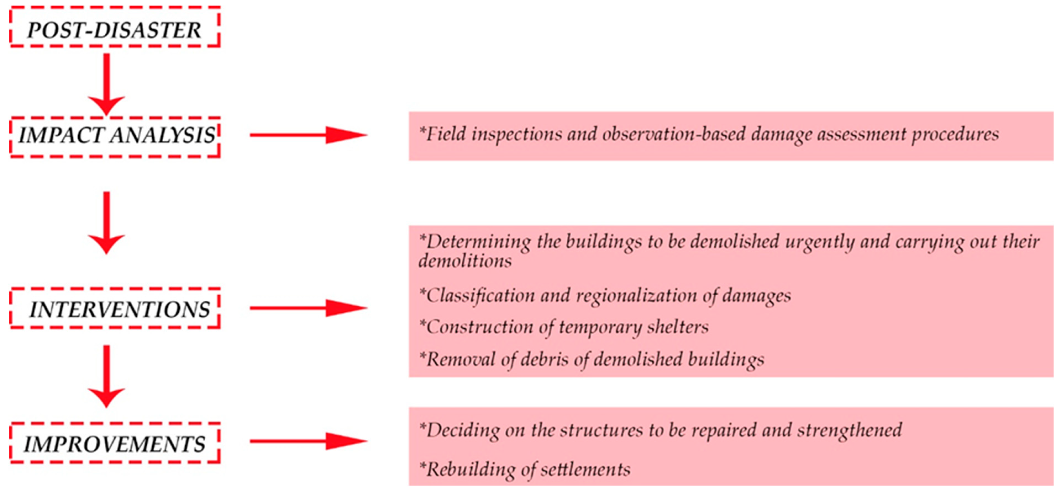
Figure 1. Post-disaster processing in terms of structural and earthquake engineering.
Geohazards 05 00036 g001
Figure 2. Flow chart diagram of this study.
Geohazards 05 00036 g002
Figure 3. View of Türkiye’s main tectonic elements and the epicenters of the Kahramanmaraş earthquakes on the current earthquake hazard map. DSF: Dead Sea Fault, EAFZ: East Anatolian Fault Zone, NAFZ: North Anatolian Fault Zone, NEAFZ: Northeast Anatolian Fault Zone, AGS: Aegean Graben System.
Geohazards 05 00036 g003
Figure 4. Acceleration–time graph: (a) 0201 Station (Mw = 7.7 Pazarcık Earthquake) and (b) 0213 Station (Mw = 7.6 Elbistan Earthquake).
Geohazards 05 00036 g004
Figure 5. Acceleration–time graph: (a) 4614 Station (Mw = 7.7 Pazarcık Earthquake) and (b) 4612 Station (Mw = 7.6 Elbistan Earthquake).
Geohazards 05 00036 g005
Figure 6. Response spectrum graph of 0201 and 0213 Stations.
Geohazards 05 00036 g006
Figure 7. Response spectrum graph of Stations 4614 and 4612.
Geohazards 05 00036 g007
Figure 8. Earthquake destruction in Kahramanmaraş province [51].
Geohazards 05 00036 g008
Figure 9. Earthquake destruction in Adıyaman province [52].
Geohazards 05 00036 g009
Figure 10. Examples of traditional school buildings with various numbers of classrooms.
Geohazards 05 00036 g010
Figure 11. View of the building under investigation.
Geohazards 05 00036 g011
Figure 12. School buildings in different typologies.
Geohazards 05 00036 g012
Figure 13. Examples of school buildings without any damage.
Geohazards 05 00036 g013
Figure 14. Examples of masonry school buildings that completely collapsed.
Geohazards 05 00036 g014
Figure 15. Examples of masonry school buildings that largely collapsed during earthquakes.
Geohazards 05 00036 g015
Figure 16. Examples of corner failure according to different weaknesses.
Geohazards 05 00036 g016
Figure 17. Local failures of the external leaf due to wall disintegration.
Geohazards 05 00036 g017
Figure 18. Examples of out-of-plane failure of the structures.
Geohazards 05 00036 g018
Figure 19. Examples of walls damaged at different levels due to various reasons.
Geohazards 05 00036 g019
Figure 20. Examples of collapsed non-load-bearing chimneys in the building.
Geohazards 05 00036 g020
Figure 21. Roof damage.
Geohazards 05 00036 g021
Figure 22. Example of damage to a tile roof.
Geohazards 05 00036 g022
Figure 23. Examples of crack damage on exterior walls.
Geohazards 05 00036 g023
Figure 24. Examples of damage to the sub-basement and bond beam.
Geohazards 05 00036 g024
Figure 25. Examples of damage caused by using wall materials with different properties.
Geohazards 05 00036 g025
Figure 26. Insufficient connection between the RC beam and structural walls.
Geohazards 05 00036 g026
Figure 27. Schematic representation of structural damage.
Geohazards 05 00036 g027
Figure 28. Damage grading used for masonry structures according to EMS-98.
Geohazards 05 00036 g028
Figure 29. Plan and view of the reference building.
Geohazards 05 00036 g029
Figure 30. 3MURI software’s 3D depiction of the school’s mathematical models.
Geohazards 05 00036 g030
Figure 31. (a) Capacity curves for the x-direction (results for all 12 analysis cases), (b) a comprehensive distribution of the damage along the wall heights (c) Capacity curve for the x-direction (worst case).
Geohazards 05 00036 g031
Figure 32. (a) Capacity curves for y-direction (results for all 12 analysis cases), (b) A comprehensive distribution of the damage along the wall heights (c) Capacity curve for y-direction (worst case).
Geohazards 05 00036 g032
Figure 33. Legend for Figure 31 and Figure 32.
Geohazards 05 00036 g033
Figure 34. Simplified procedure.
Geohazards 05 00036 g034
Figure 35. Seismic strengthening objectives for existing buildings; (a) Increment of ductility, (b) Increment of strength and stiffness, and (c) Increment of strength, stiffness, and ductility [83].
Geohazards 05 00036 g035
Figure 36. Suggested retrofitting for the existing building.
Geohazards 05 00036 g036
Table 1. The highest measured acceleration values for Kahramanmaraş and Adıyaman [49,50].
StationPGA
N-S (cm/s2)
PGA
E-W (cm/s2)
PGA
UD (cm/s2)
Repi (km)
6 February 2023 04:17 Mw = 7.7 (Pazarcık- Kahmaranmaraş) (Depth = 8.6 km)
4614 Pazarcık/Kahramanmaraş2165.622178.721951.6831.42
0201 Center/Adıyaman474.12879.95318.97120.12
6 February 2023 13:24 Mw = 7.6 (Elbistan-Kahramanmaraş) (Depth = 7 km)
4612 Kahramanmaraş/Göksun635.45523.21494.9166.68
0213 Tut/Adıyaman121.30126.6271.3568.73
Table 2. Population, employment, and number of damaged buildings in the Kahramanmaraş and Adıyaman provinces.
CityPopulationEmploymentNumber of Affected BuildingsNumber of Heavily Damaged + Demolished ResidencesNumber of Moderately Damaged Residences Number of Slightly Damaged Residences
Kahramanmaraş 1,177,436338,000243,15399,32617,887161,137
Adıyaman 812,580122,000120,49656,25618,71572,729
Earthquake Zone (Total)14,013,1963,841,0002,618,697518,009131,5771,279,727
Total percentage of two cities within the earthquake zone (%)141213.8302818
Table 3. Distribution of the investigated masonry structures according to their damage levels.
Damage GradeNumber of Buildings
No damage59
Grade 127
Grade 25
Grade 312
Grade 414
Grade 57
Table 4. PGA limit states for the existing building.
Limit StatesPeak Ground Acceleration (PGA (g))
Damage Limitation (DL)0.127
Significant Damage (SD)0.201
Near Collapse (NC)0.299
Table 5. PGA limit states after retrofitting.
Limit StatesPeak Ground Acceleration (PGA (g))
DL0.189
SD0.323
NC0.411
Disclaimer/Publisher’s Note: The statements, opinions and data contained in all publications are solely those of the individual author(s) and contributor(s) and not of MDPI and/or the editor(s). MDPI and/or the editor(s) disclaim responsibility for any injury to people or property resulting from any ideas, methods, instructions or products referred to in the content.