1. Introduction
Beketov pioneered the aluminothermic reduction process in 1859 [
1]. Once lower-cost aluminium became available in the 19th century, the practical application of aluminothermic reduction expanded through the work of Beketov and Goldschmidt, respectively [
1]. Thermic reduction with Al or Si as reductant is a well-established method of producing low-carbon ferroalloys of manganese and chromium from a molten slag [
2]. Medium–carbon ferromanganese (MCFeMn) can be produced by thermic reduction or via oxygen refining of high-carbon ferromanganese (HCFeMn). Silicothermic reduction of manganese oxide-based slags is performed in an electric furnace because the exothermic heat generated by silicothermic reduction is insufficient to meet overall process heat requirements [
2]. Low-carbon ferromanganese (LCFeMn) is only produced with silicothermic reduction because of excessive manganese losses in oxygen refining.
Table 1 presents the chemical compositions of the various carbon ferromanganese alloys [
3]. The silicon reductant is sourced as silicomanganese alloy of 16–30% Si for medium-carbon ferro-manganese production, and 32–33%Si for low-carbon ferro-manganese production. The silico-manganese minimum %Si content is selected based on the target %C in the product alloy because the carbon solubility in Fe–Mn–Si–C alloys decreases drastically with increased %Si [
2]. The need for low-carbon and low-phosphorus manganese alloys is motivated in the production of transformation-induced plasticity (TRIP) and twinning-induced plasticity (TWIP) steels since these grades contain high manganese (15–25% Mn), silicon (3%), and aluminium (3%) and low carbon levels (0.01% C) [
4]. Furthermore, the application of aluminium-silicon-manganese (AMS), ferromanganese-aluminium (FMA), and ferrosiliconmanganese–aluminium (FAMS) complex alloys in conventional steelmaking plants is more efficient than adding individual deoxidiser alloys [
5,
6]. These alloys are produced in electric furnaces operated at high temperatures, using coke as a reductant to reduce Al
2O
3 to Al [
6].
The application of aluminium as a reductant opens the possibility of a circular process with reduced CO
2 emissions as proposed in recent studies [
7,
8,
9,
10]. These studies explain that since aluminium is produced electrochemically in the Hall–Héroult process, and the slag and aluminium are reacted in an electric furnace, most of the process CO
2 formation can be negated. Recent work applied discarded smelter slag as the MnO source in aluminothermic reduction since much MnO slag is stockpiled [
7,
8]. However, these slags are currently produced as a by-product or discard product of carbothermic reduction processes. Therefore, applying aluminothermic reduction with the ore as the starting material in a single step can provide a simplified circular process [
7,
8,
9,
10]. Some examples of this approach are already being used industrially. For example, low-carbon ferro-manganese production from roasted low-grade manganese ore is described in [
11]. Pre-roasting of the ore is required to convert MnO
2 to Mn
2O
3 or Mn
3O
4, thereby decreasing the violent heat release during aluminothermic reduction with MnO
2 [
11]. The ore feed requirement is a minimum of 46% Mn and a Mn/Fe ratio of 9, with a P content below 0.12%. CaF
2 is added as a flux [
11]. The product alloy composition ranged from 70–84% Mn, 13–16% Fe, 1–10% Si, <0.03% Al, and <0.24% P, and the metal yield was 58–64%.
Researching the fundamentals of the aluminothermic reduction reaction is complicated by the rapid release of heat from the exothermic reaction between Al and oxidants. The implication is that the reaction system is reacted under non-isothermal conditions, which complicates the kinetic analysis [
12]. Oxidants other than air may be added deliberately as an additive, or the oxides targeted for the reduction reaction may form the dual purpose of oxidant and metal/alloy product former. In some studies the mixture is reacted under a protective gas atmosphere, such as Argon gas, to eliminate oxygen in the air from reacting with the feed mixture [
8,
9,
13]. However, it has been shown that some air is required to initiate the reaction in MnO
2–Al mixtures since this mixture did not act under Argon gas [
12]. Therefore, varied reaction mixtures have been reported in the literature with different particle sizes, aluminium-to-oxide ratios, mixture compaction extents, oxide and metal solution phases formed, reactor materials, and, most importantly, inert or oxygen-containing atmosphere selection, with or without ignition chemicals or oxidants [
8,
9,
11,
12,
13,
14]. Industrial applications typically do not use expensive inert atmospheric gases for shielding against air; therefore, process feasibility must be tested in an air atmosphere first. This effect is observed in the work of Sarangi et al. [
12], where a fundamental kinetic study on MnO
2–Al mixtures was conducted in static air, following the failure of the reaction under an Argon atmosphere. Activation energy values ranging from −518 kJ/mol to −910 kJ/mol were reported for heating rates of 5 K/min and 15 K/min [
12]. In comparison, 284 kJ/mol was reported for 5 µm Al reacted, versus 416 kJ/mol for nano-Al reacted at a heating rate of 10 K/min [
15]. In the low-temperature (750–850 °C) reaction of MnO and Mn
3O
4 with a stirred aluminium bath in air, activation energy values of 330 kJ/mol and 36 kJ/mol were reported [
16]. It is clear that the rate constant values from each study result in apparent activation energy values peculiar to the specific factors of the reactant mixture, such as particle size, mixture compaction density, and phase chemistry changes with reaction progress [
12,
15,
16]. Thus, in the aluminothermic reduction process, the attainment of liquid slag and alloy from the aluminothermy heat and mixture formulation is the first process requirement to ensure optimal separation of the produced alloy from the slag.
Since Al
2O
3 has a high melting point, the slag chemistry must be designed to flux most Al
2O
3. Thus, the slag volume can be excessive, and the phase chemistry of the slag will influence the ease of subsequent processing for hydrometallurgical recovery of Al
2O
3 [
7,
8,
17,
18]. Since CaO and Al
2O
3 form low liquidus compounds and CaO in the slag increases the activity of MnO in the slag to promote aluminothermic reduction of MnO, the aim slag of CaO-Al
2O
3 was applied [
7,
8]. The leaching of Al from CaO-Al
2O
3 slag has been demonstrated in a 10% Na
2CO
3 solution, reacted at 30–45 °C [
17]. Only a small quantity of the silicate phase was not leachable. Another approach is a Na
2O-Al
2O
3-based slag since the NaAlO
2 compound is easily leached in water [
18]. Adequate leaching conditions were identified at a solid–liquid ratio of 1:10 with a leaching time of 60 min at 60 °C. The leachate contained Na
+:Al
3+ at 1.43:1. Carbonation with CO
2 gas bubbled through the solution at 80 °C resulted in a pH of 12.5–10.5 for 96.5% Al recovery as α-Al(OH)
3 (Bayerite) particles of 90% +44 μm and 98.8% alumina grade, suitable for feed to the Hall–Héroult process after calcination to α-Al
2O
3 [
18].
This work aims to formulate and test a suitable slag formulation for the application of circular processing of aluminium as the primary reductant in manganese ore reduction, producing a low-carbon ferro–manganese alloy. The slag must have high Al2O3 solubility to effect adequate alloy–slag separation and must allow the Al2O3 product to be recovered via hydrometallurgy. The synergistic effect of carbon and silicon reductants with aluminium is illustrated and compared to distinct scenarios, as well as to the test result with only carbon as a reductant.
3. Results
The base case sample did not form any significant metal within the reaction time, and at the low temperature of the muffle furnace (1350 °C), the crucible contents consisted of a loosely sintered mixture. The magnetic fraction of this sample is shown in
Figure 1a.
Figure 1b,c show that large alloy blobs were effectively separated from the slag in samples A and C, with some smaller metal droplets. It is seen that sample A formed one large alloy volume, and sample C formed multiple smaller alloy volumes. Thus, in sample A with added C and Al, and sample C with added C, Si, and Al, clear slag and alloy formation and separation were achieved.
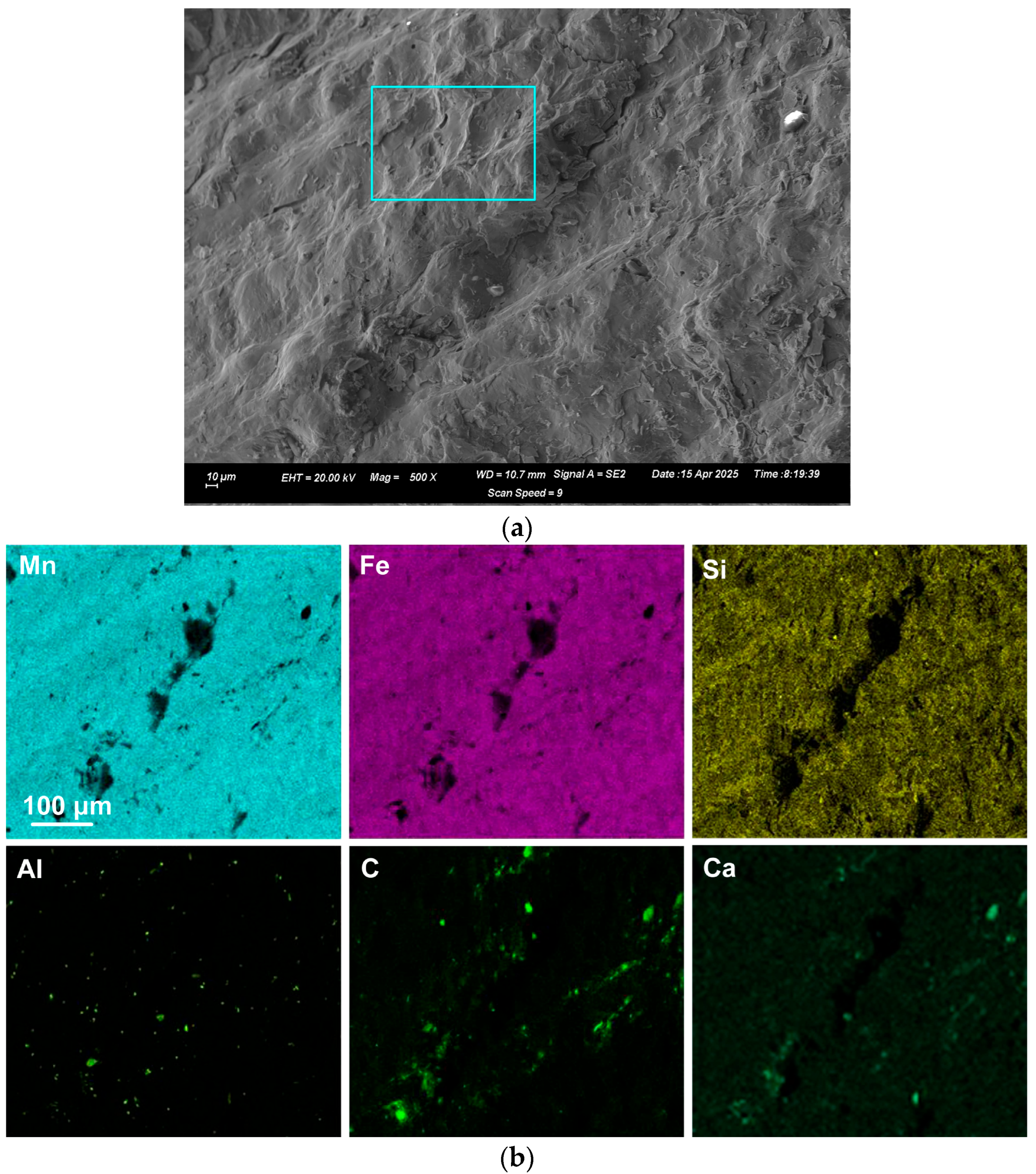
EDX was applied to measure the alloy composition from the fractured surface made through the large alloy volume. A typical analysis area consisted of 0.5 mm × 0.5 mm, as shown for samples A and C alloy in
Figure 2,
Figure 3 and
Figure 4; the analysis of these areas is summarised in
Table 4 and
Table 5. The bulk alloy analyses are also presented in
Table 4 and
Table 5, particularly the %C, as it is not accurately analysed by SEM-EDX. The analyses per area in each sample are closely matched. The main difference is evident in the increased silicon content in some regions of sample C (areas 8–10), most likely due to the incorporation of Si metal powder into the bulk alloy volume. The element maps in
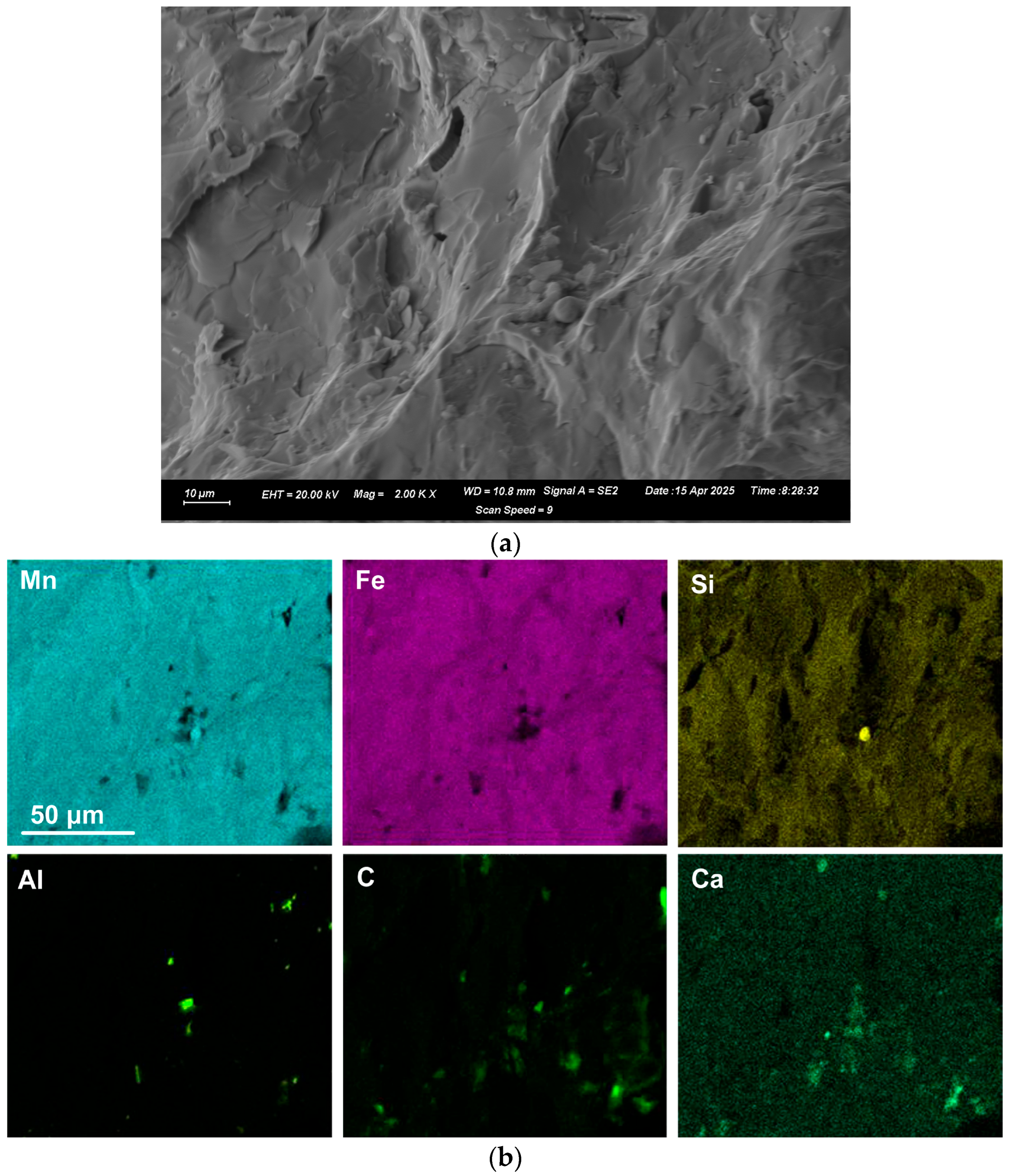
Figure 2 and
Figure 3 indicate that the alloy matrix primarily consists of a Mn–Fe–Si alloy, with Al, Ca, and C appearing as specks. The C appears as surface flakes rather than being dissolved into the alloy. This is better seen in
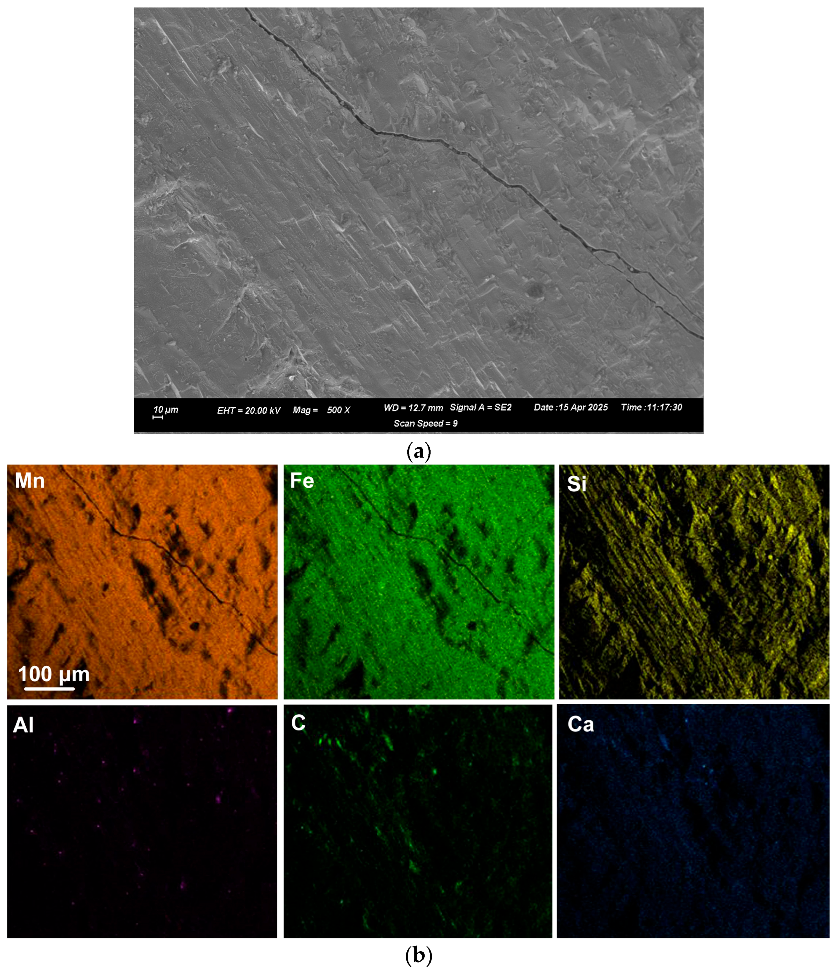
Figure 2b at the higher magnification of 2000X. The element maps for sample C in
Figure 4b appear similar to those for sample A in
Figure 2 and
Figure 3. The slight difference is that no V was analysed. Some S was also analysed as displayed in
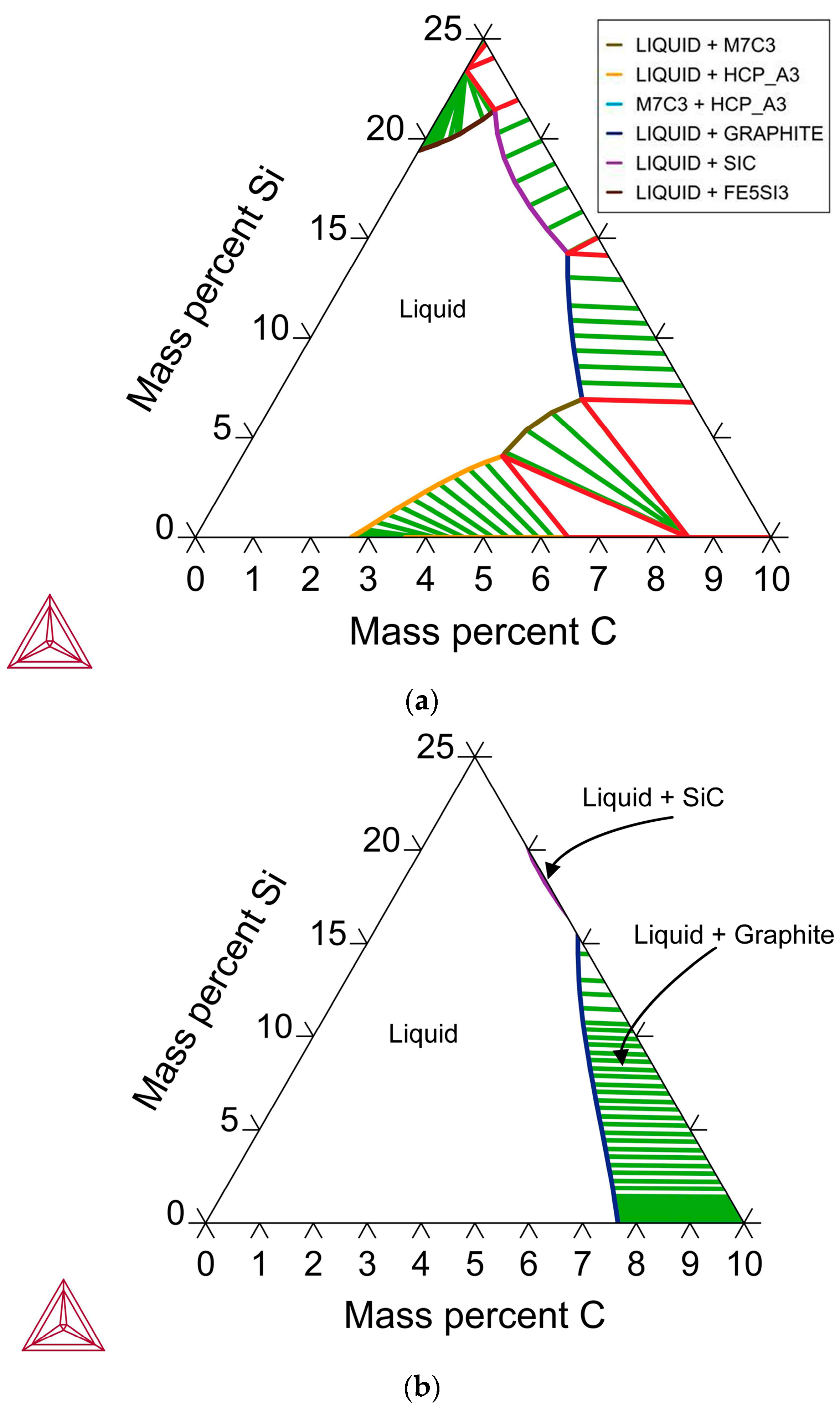
Table 5 and confirmed to be present in both sample A and sample C bulk alloy analyses at 0.03% S and 0.08% S, respectively. The bulk alloy %C decreased with increased %Si, with 3.5% C at 1.4% Si in sample A alloy and 2.2% C at 8.7% Si in sample C alloy. The low Al content in both alloys confirms that the aluminium content addition in
Table 3 is close to optimal. Too little Al addition would cause insufficient reduction of the ore, and too much Al addition would cause a high alloy %Al.


