
Design and Experimental Investigation of Pneumatic Drum-Sieve-Type Separator for Transforming Mixtures of Protaetia Brevitarsis Larvae

Abstract
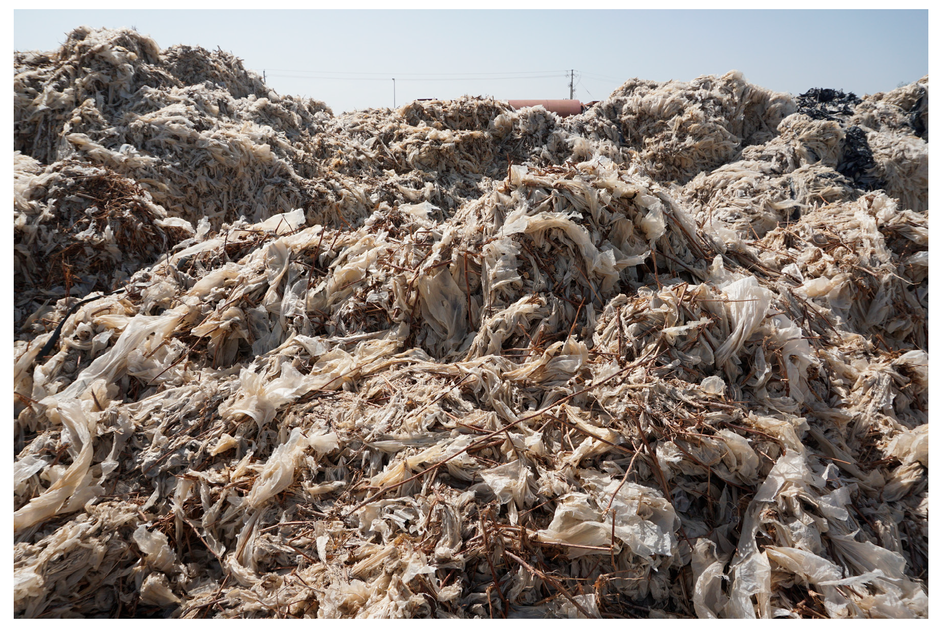
1. Introduction
2. Determination of Material Parameters of Conversion Mixtures
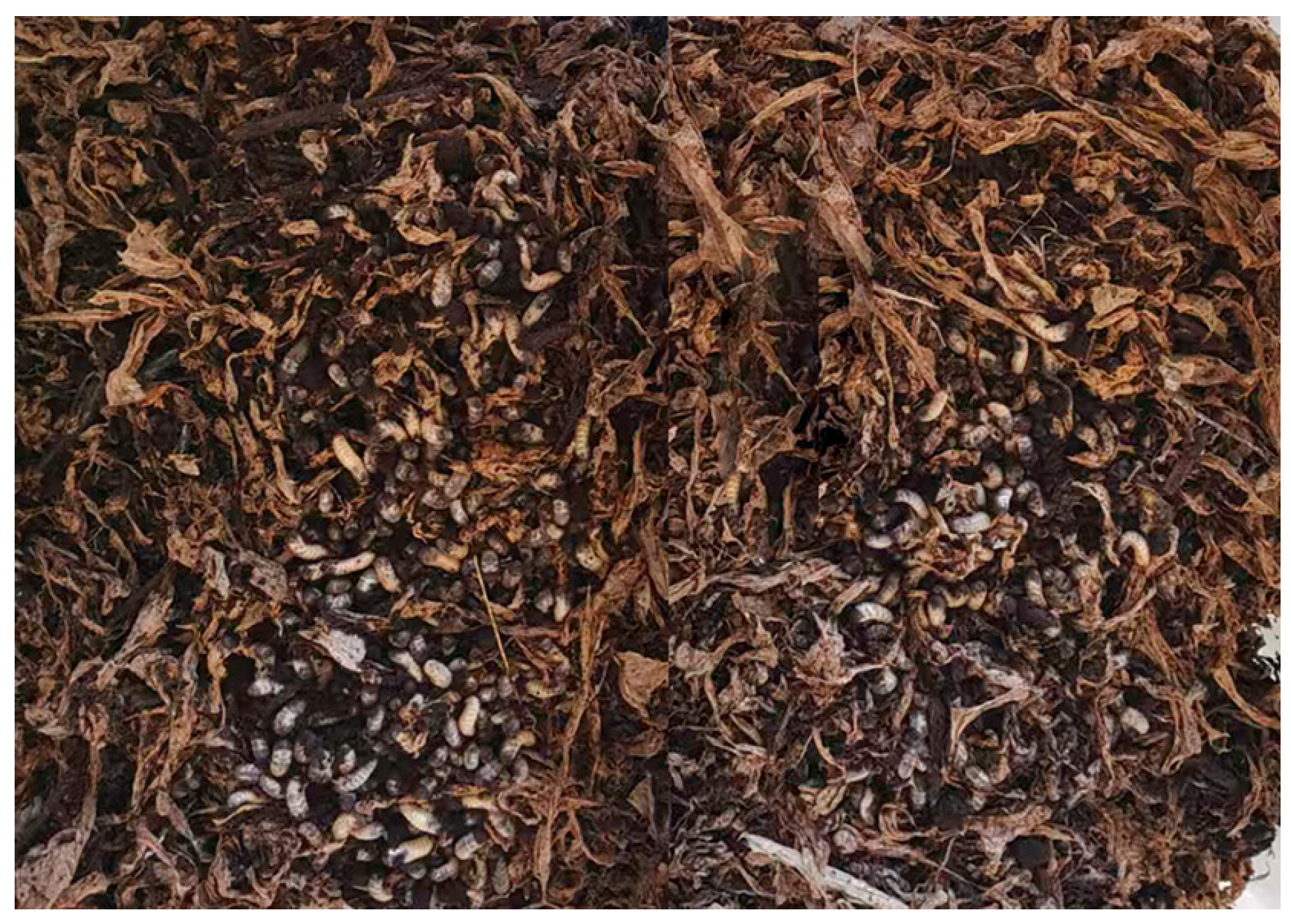
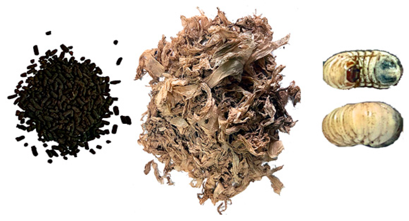
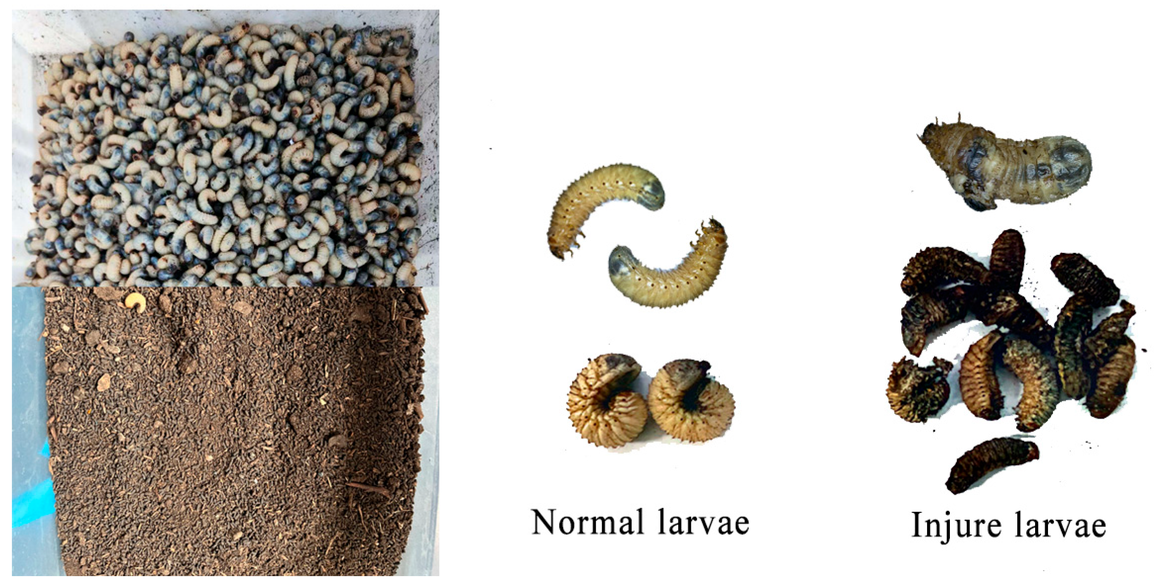
2.1. Determination of Physical Parameters of Mixture
2.2. Suspension Velocity of Transformants
3. Structure and Working Principle of Whole Machine
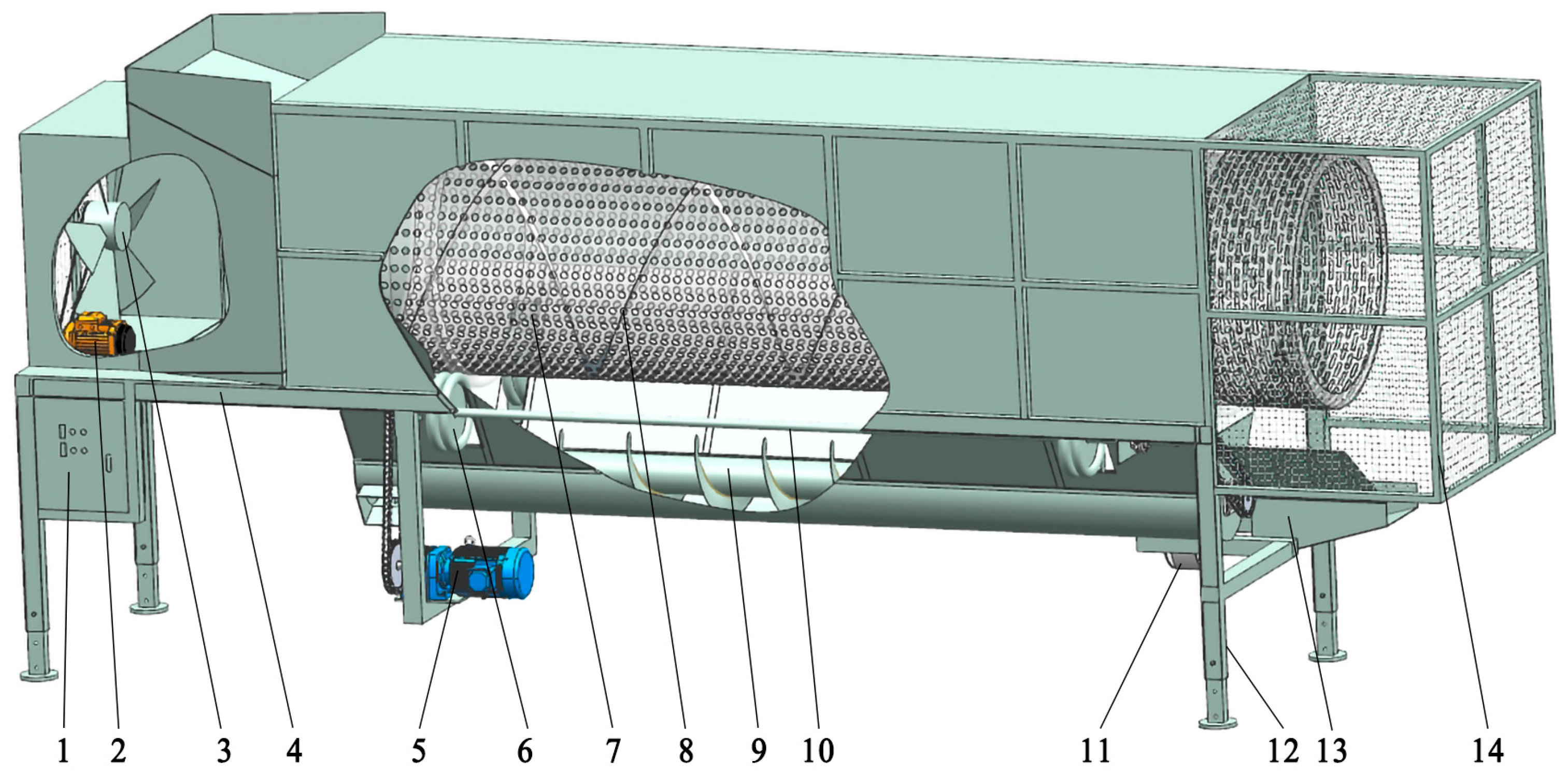
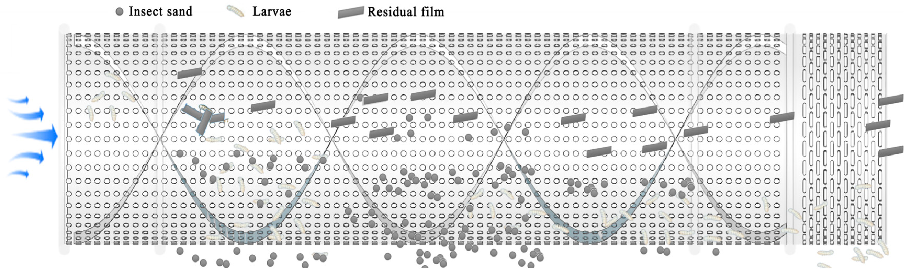
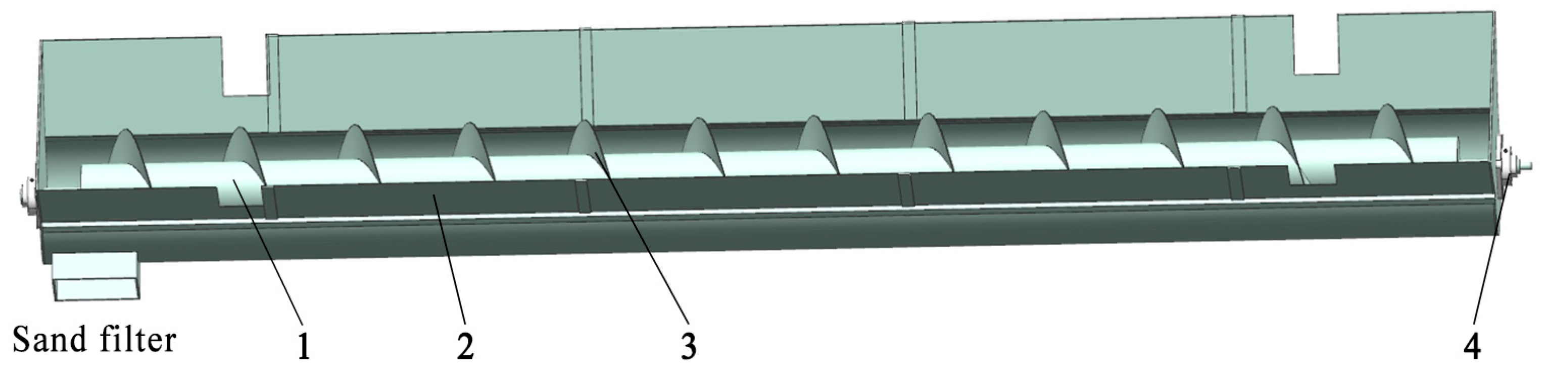
3.1. Structure of the Whole Machine
3.2. Working Principle
4. Key Component Design and Parameter Analysis
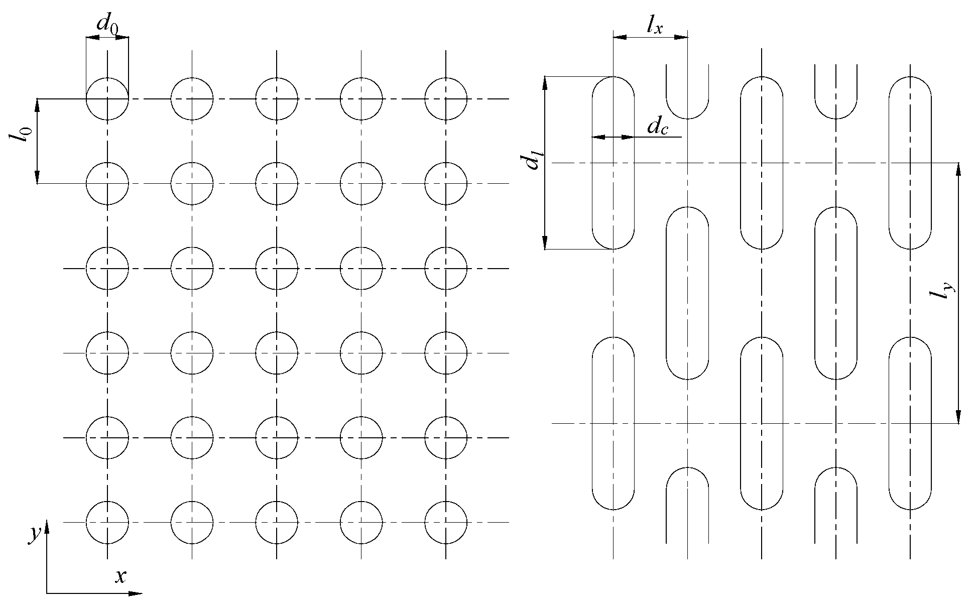
4.1. Design of Segmented Sieve Cylinder
4.1.1. Determination of Perforations of Sieve Cylinder
4.1.2. Determination of the Diameter and Length of the Sieve Cylinder
4.1.3. Determination of the Rotational Speed of the Sieve Cylinder
4.1.4. Determination of Spiral Blade Structure and Parameters
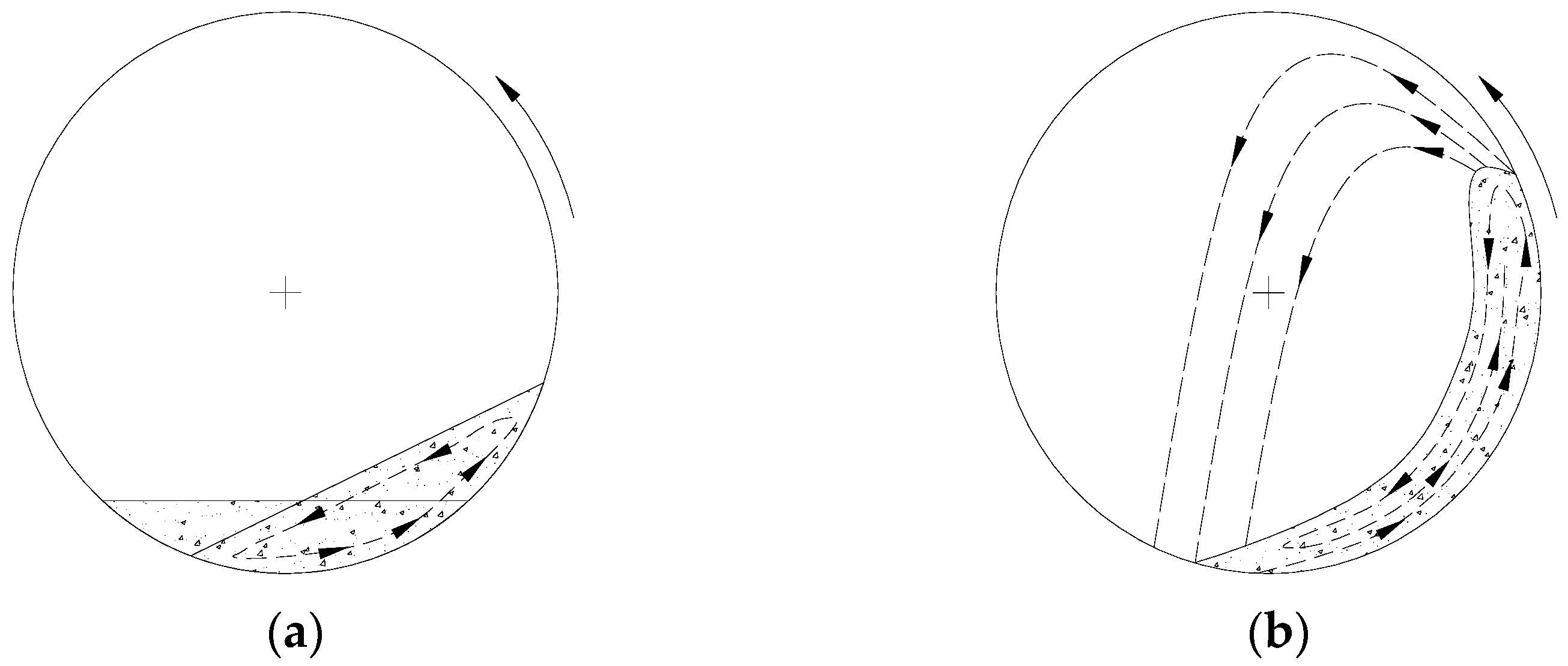
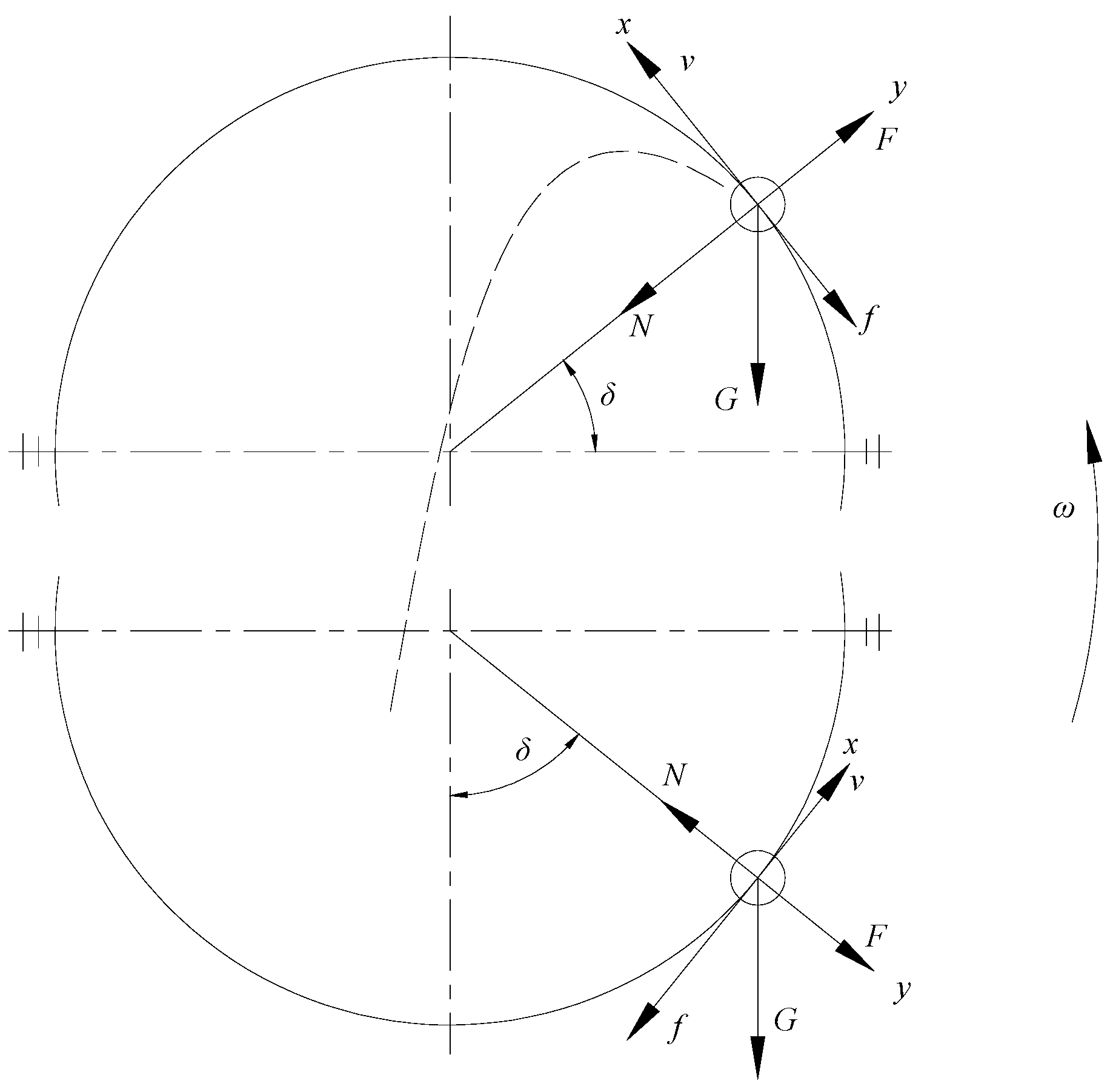
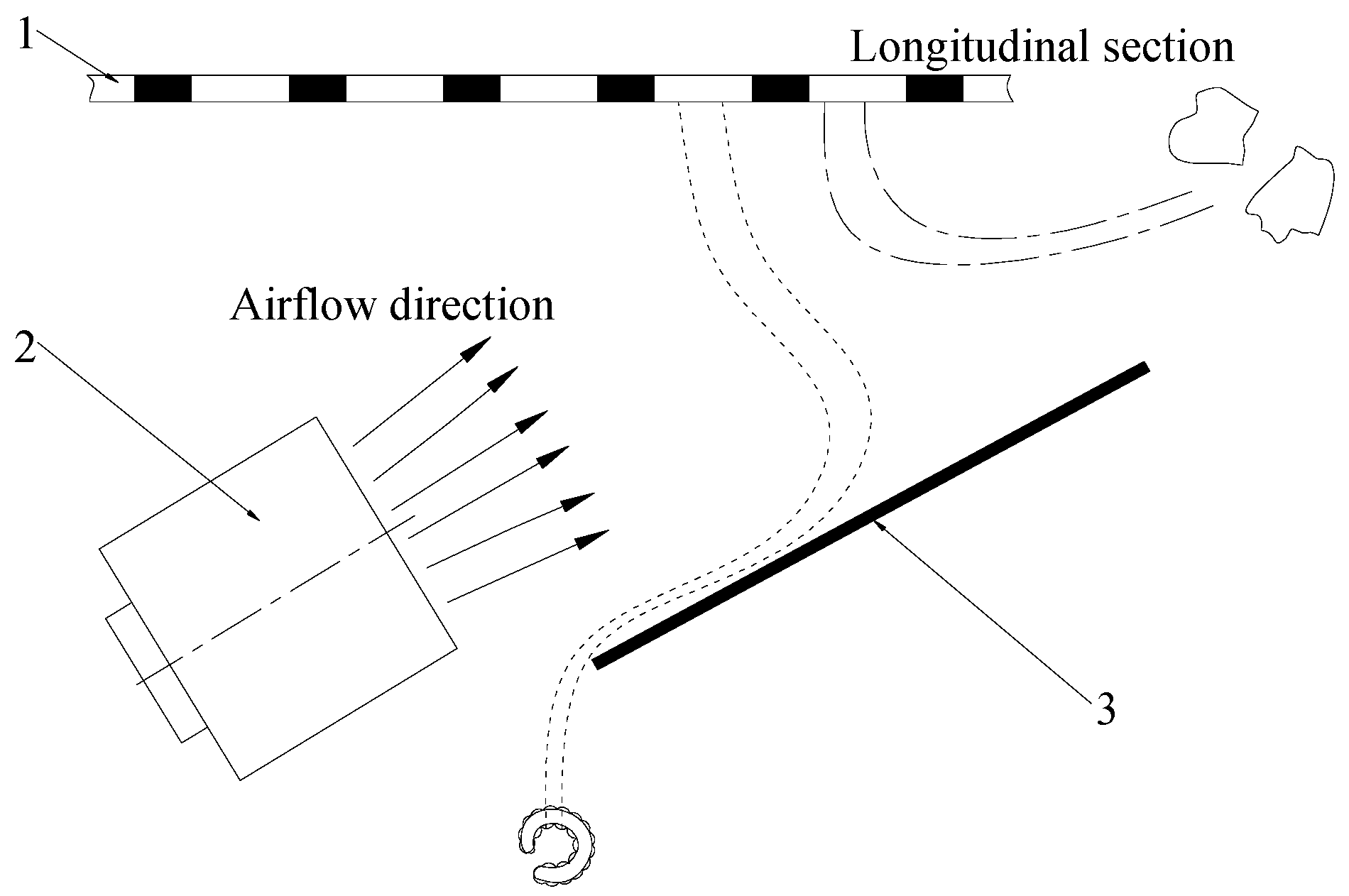
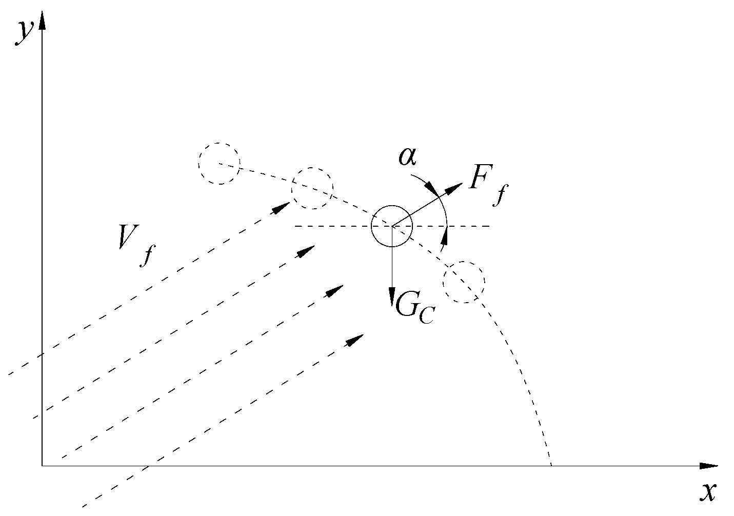
4.2. Kinematic Analysis of Secondary Separation Process of Larvae and Residual Film
4.3. Design of Insect-Sand-Conveying Winch
5. Experiments and Analyses
5.1. Single-Factor Test
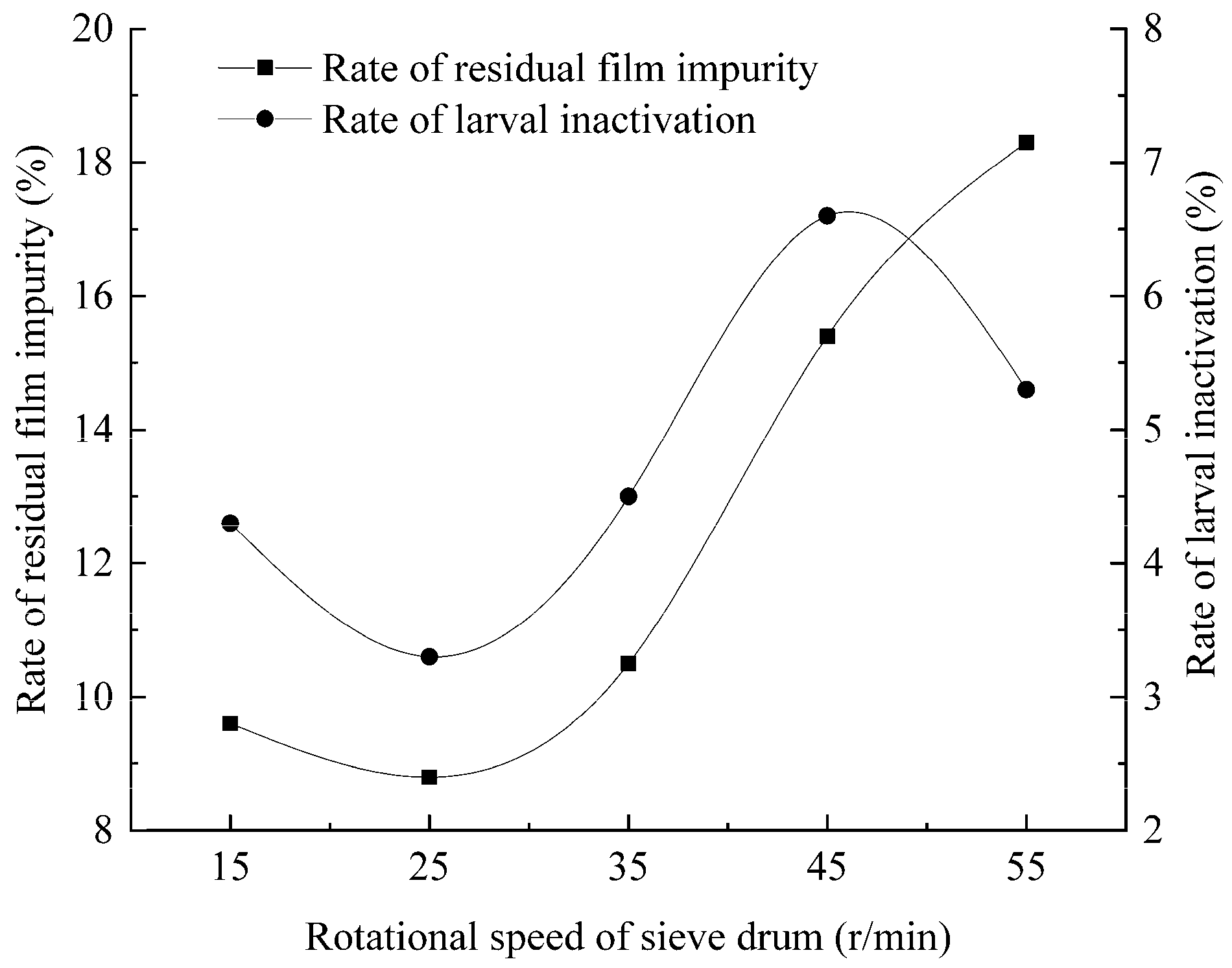
5.1.1. Influence of Sieve Cylinder Rotational Speed on Sieving Effect
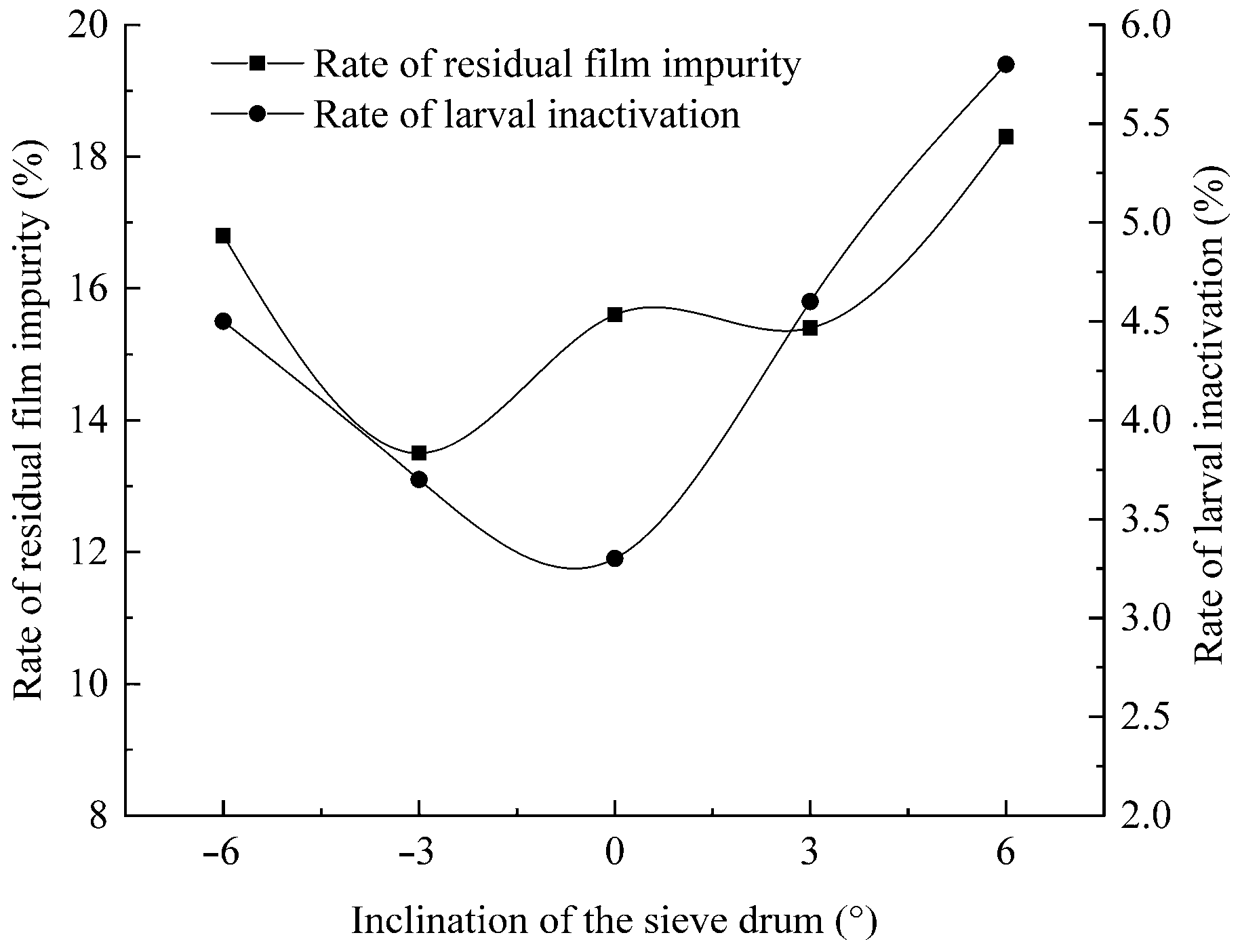
5.1.2. Influence of Sieve Cylinder Inclination Angle on Sieving Effect
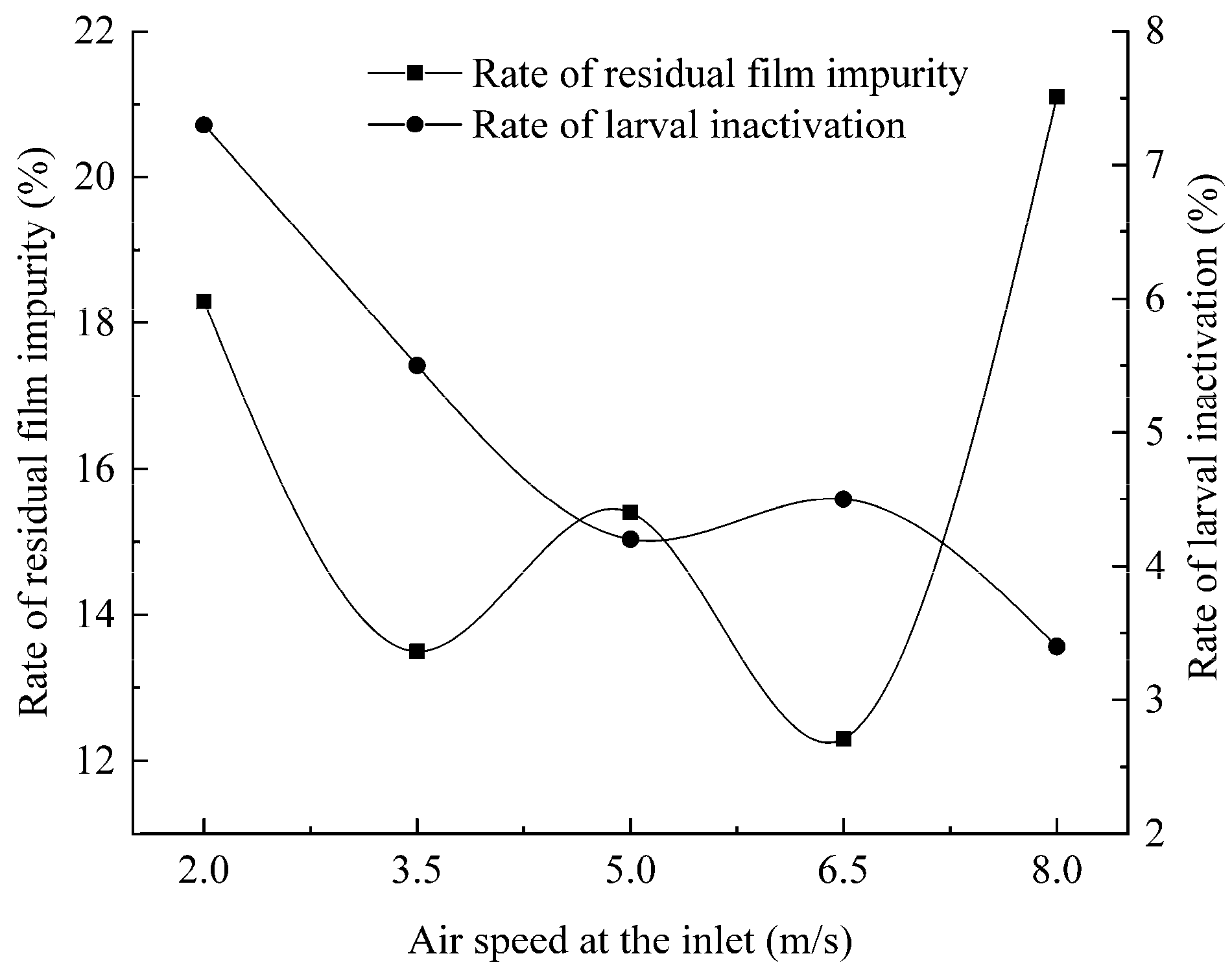
5.1.3. Influence of Inlet Air Velocity on Sieving Effect
5.2. Test Program
5.3. Variance Analysis
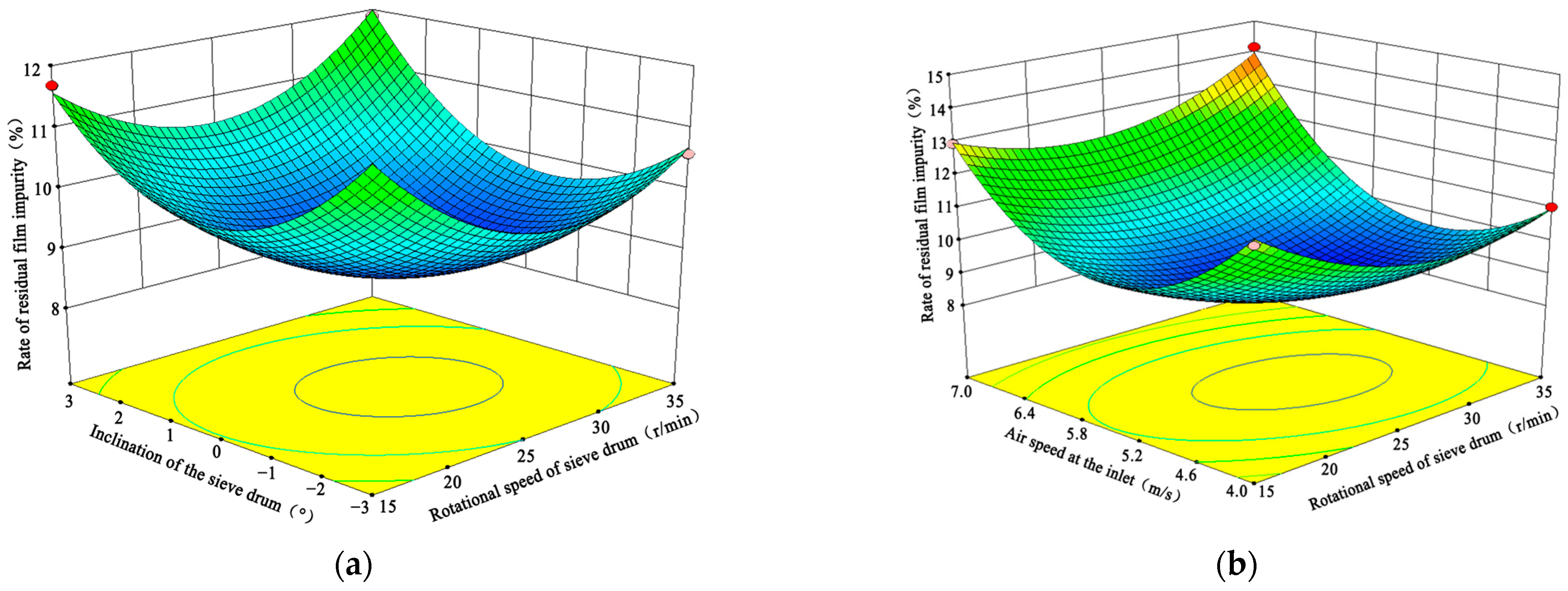
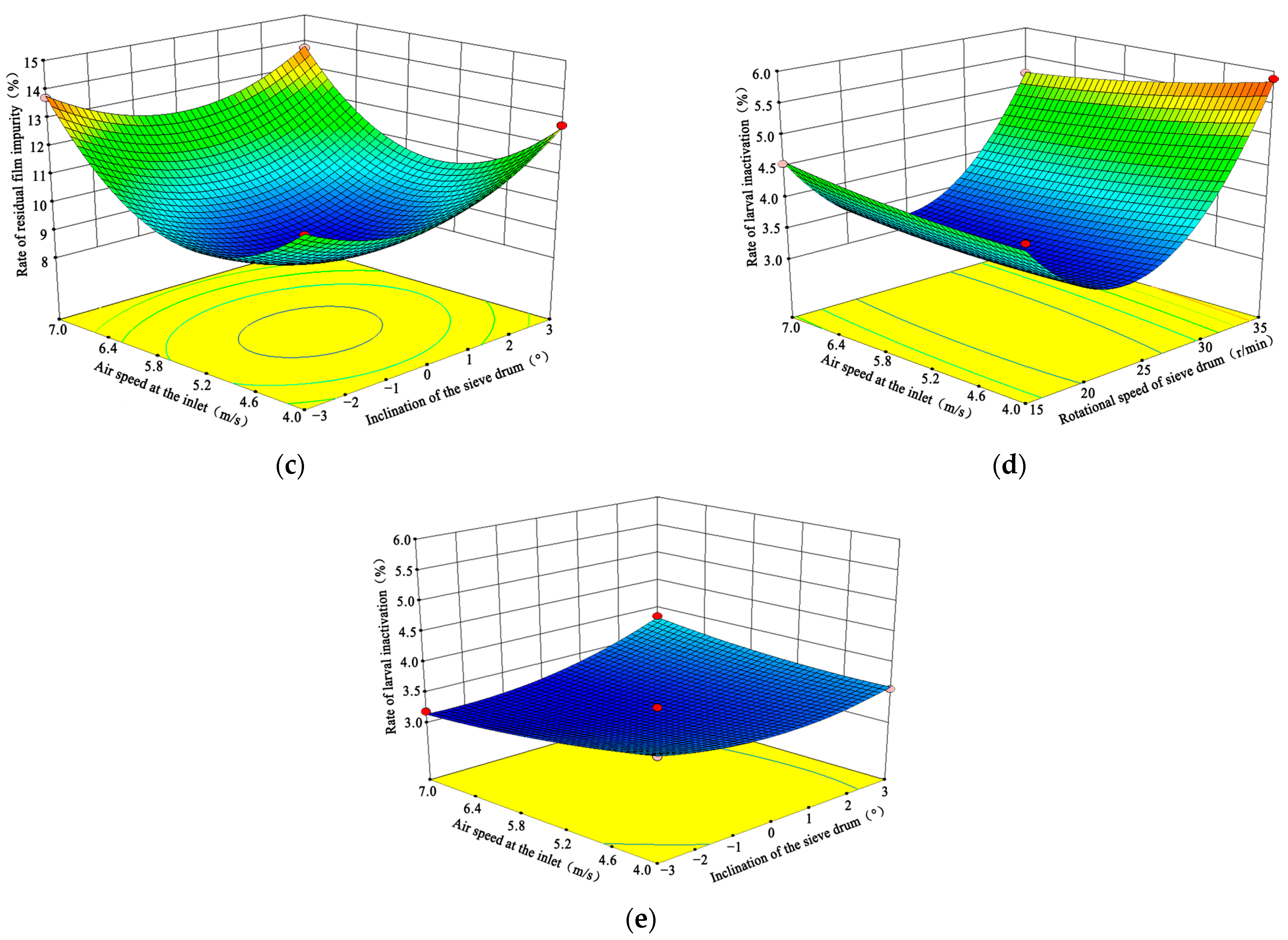
5.4. Response Surface Analysis
5.5. Optimization of Parameters
5.6. Experimental Verification
6. Conclusions
Author Contributions
Funding
Data Availability Statement
Acknowledgments
Conflicts of Interest
References
- Zhang, B.; Liang, R.; Li, J.; Li, Y.; Meng, H.; Kan, Z. Test and Analysis on Friction Characteristics of Major Cotton Stalk Cultivars in Xinjiang. Agriculture 2022, 12, 906. [Google Scholar] [CrossRef]
- Zhang, G.; Zhang, S.; Xia, Z.; Wu, M.; Bai, J.; Lu, H. Effects of Biodegradable Film and Polyethylene Film Residues on Soil Moisture and Maize Productivity in Dryland. Agriculture 2023, 13, 332. [Google Scholar] [CrossRef]
- Yang, H.; Hu, Z.; Wu, F.; Guo, K.; Gu, F.; Cao, M. The Use and Recycling of Agricultural Plastic Mulch in China: A Review. Sustainability 2023, 15, 15096. [Google Scholar] [CrossRef]
- Xue, S.; Chen, X.; Li, J.; Wang, X.; Zhang, Z. Design of and Experiment on a Film Removal Device of an Arc-Toothed Residual Film Recovery Machine before Sowing. Appl. Sci. 2021, 11, 8551. [Google Scholar] [CrossRef]
- Alabi, O.A.; Ologbonjaye, I.A.; Awosolu, O.; Alalade, O.E. Public and environmental health effects of plastic wastes disposal: A review. J. Toxicol. Risk Assess 2019, 5, 1–13. [Google Scholar]
- Hao, A.; Yin, C.; Léonard, A.; Dogot, T. Cost–Benefit Analysis of Mulch Film Management and Its Policy Implications in Northern China. Agriculture 2024, 14, 1081. [Google Scholar] [CrossRef]
- Ivankovic, T.; Jurišic, V. Advances in Waste Treatment and Resource Utilization. Appl. Sci. 2023, 13, 11500. [Google Scholar] [CrossRef]
- Yimei, L.; Tong, F.; Lili, G.; Yu, S.; Haiyan, C.; Fushun, L.; Chunqin, L.; Fuping, S.; Jie, Z.; Changlong, S. Protaetia brevitarsis larvae can efficiently convert herbaceous and ligneous plant residues to humic acids. Waste Manag. 2019, 83, 79–82. [Google Scholar] [CrossRef] [PubMed]
- Guangjie, Z. Studies on the Transformation Techniques of Organic Waste Using Protaetia brevitarsis (Coleoptera: Cetoniidae). Master’s Thesis, Shandong Agricultural University, Tai’an, China, 2019. [Google Scholar]
- Badretdinov, I.; Mudarisov, S.; Lukmanov, R.; Permyakov, V.; Nasyrov, R. Mathematical Modeling and Research of the Work of the Grain Combine Harvester Cleaning System. Comput. Electron. Agric. 2019, 165, 104966. [Google Scholar] [CrossRef]
- Li, Y.; Xie, J.; Zhang, J.; Yue, Y.; Meng, Q.; Du, Y.; Ma, D. Parameter calibration and experimental verification of discrete element simulation model for Protaetia brevitarsis larvae bioconversion mixture. Intern. J. Agric. Biol. Eng. 2024, 17, 35–44. [Google Scholar]
- Yuan, J.; Wu, C.; Li, H.; Qi, X.; Xiao, X.; Shi, X. Movement rules and screening characteristics of rice-threshed mixture separation through a cylinder sieve. Comput. Electron. Agric. 2018, 154, 320–329. [Google Scholar] [CrossRef]
- Sharma, K.; Patel, S.; Jha, S.N.; Devi, M.; Vishwakarma, R.K. Rotating orifice feeding system for continuous and uniform discharge of makhana seeds (Euryale ferox). J. Food Eng. 2021, 299, 110504. [Google Scholar] [CrossRef]
- Wang, L.; Chai, J.; Wang, H.; Wang, Y. Design and performance of a countersunk screen in a maize cleaning device. Biosyst. Eng. 2021, 209, 300–314. [Google Scholar] [CrossRef]
- Chen, P.; Han, Y.; Jia, F.; Zhao, D.; Meng, X.; Li, A.; Chu, Y.; Zhao, H. Investigation of the mechanism of aerodynamic separation of rice husks from brown rice following paddy hulling by coupled CFD-DEM. Biosyst. Eng. 2022, 218, 200–215. [Google Scholar] [CrossRef]
- Kong, X.; Liu, J.; Yang, T.; Su, Y.; Geng, J.; Niu, Z. Numerical simulation of feed pellet breakage in pneumatic conveying. Biosyst. Eng. 2022, 218, 31–42. [Google Scholar] [CrossRef]
- Grajales, L.M.; Xavier, N.M.; Henrique, J.P.; Thoméo, J.C. Mixing and motion of rice particles in a rotating drum. Powder Technol. 2012, 222, 167–175. [Google Scholar] [CrossRef]
- Liao, C.C.; Hsiau, S.S.; Nien, H.C. Effects of density ratio, rotation speed, and fill level on density-induced granular streak segregation in a rotating drum. Powder Technol. 2015, 284, 514–520. [Google Scholar] [CrossRef]
- Zhang, L.; Ma, J.; Wang, Z.; Qin, H.; Bai, J.; Wang, Q. Effect of moving baffle on average velocity and mixing of binary particles in rotating drums. J. Cent. South Univ. 2020, 27, 478–489. [Google Scholar] [CrossRef]
- Zhao, L.; Zhao, Y.; Bao, C.; Hou, Q.; Yu, A. Optimisation of a circularly vibrating screen based on dem simulation and taguchi orthogonal experimental design. Powder Technol. 2017, 310, 307–317. [Google Scholar] [CrossRef]
- Wang, J.; Li, Z.; Hussain, S.; Lu, Q.; Song, H.; Zheng, D. Design and threshing outputs study of internal and external rotary roller buckwheat thresher. INMATEH-Agric. Eng. 2020, 60, 173–182. [Google Scholar] [CrossRef]
- Jin, W.; Zhang, X.; Ding, Y.; Bai, S.; Liu, W.; Zhou, X. Experiment on suspension separation of residual film and impurity based on EDEM-Fluent coupling. Trans. Chin. Soc. Agric. Mach. 2022, 53, 89–98. [Google Scholar]
- Mohamed Halim, R.; Ramli, R.; Che Mat, C.R.; Yuen May, C.; Abu Bakar, N.; Abdul Hadi, N. Dry Separation of Palm Kernel and Palm Shell Using a Novel Five-Stage Winnowing Column System. Technologies 2016, 4, 13. [Google Scholar] [CrossRef]
- Zhu, X.; Xu, Y.; Han, C.; Yang, B.; Luo, Y.; Qiu, S.; Huang, X.; Mao, H. Parameter calibration and experimental verification of the discrete element model of the edible sunflower seed. Agriculture 2025, 15, 292. [Google Scholar] [CrossRef]
- Dai, F.; Guo, W.; Song, X.; Shi, R.; Qu, J.; Zhao, W. Measurement and simulation of the suspension velocity of flax threshing material using CFD-DEM. Int. J. Agric. Biol. Eng. 2021, 14, 230–237. [Google Scholar] [CrossRef]
- Chen, B.; Wang, B.; Yan, J.H.J. Optimization research on screening parameters of elliptical vibrating screen based on DEM theory. Proc. Inst. Mech. Eng. Part E J. Process Mech. Eng. 2022, 236, 1992–2000. [Google Scholar] [CrossRef]
- Ferrer, H.P. Screening Theory and Practice; Butterworths: London, UK, 1968; pp. 12–34. [Google Scholar]
- Zhang, H.; Zhou, Z.; Qu, Z.; Li, Z.; Wang, W. Simulation and Experiment of Sieving Process of Sieving Device for Tiger Nut Harvester. Agriculture 2022, 12, 1680. [Google Scholar] [CrossRef]
- Peng, C.; Zhou, T.; Song, S.; Sun, S.; Yin, Y.; Xu, D. Design and Experiment of Black Soldier Fly Frass Mixture Separation through a Cylinder Sieve with Different Rotation Speeds. Appl. Sci. 2022, 12, 10597. [Google Scholar] [CrossRef]
- Wan, X.; Shu, C.; Xu, Y.; Yuan, J.; Li, H.; Liao, Q. Design and experiment on cylinder sieve with different rotational speed in cleaning system for rape combine harvesters. Trans. Chin. Soc. Agric. Eng. 2018, 34, 27–35. [Google Scholar]
- Shi, X.; Niu, C.; Wang, X.; Zhang, H.; Yang, H. Design of roller sieve waste plastic film and trash winnowing machine. Trans. Chin. Soc. Agric. Eng. 2017, 33, 19–26. [Google Scholar]
- Zheng, W.; Ma, L.; Liu, J.; Yan, B.; Duan, Y.; Chen, S.; Lyu, J.; Xiang, W. Simulation and Test of Key Decorticating Components of Spiral Ramie Decorticator. Agronomy 2025, 15, 122. [Google Scholar] [CrossRef]
- Wang, L.; Yu, Y.; Zhang, S.; Feng, X.; Song, L. Bionic design and performance test of maize grain cleaning screen through earthworm motion characteristics. Int. J. Agric. Biol. Eng. 2021, 14, 12–21. [Google Scholar] [CrossRef]
- Xie, J.; Liu, W.; Cao, S.; Huang, W.; Zhang, J.; Li, Y.; Meng, Q. Design and Test of Countercurrent Hook-type Residual Film Mixture Cleaning and Separation Device. Trans. Chin. Soc. Agric. Mach. 2025, 56, 397–408. [Google Scholar]
- Li, J.; Xu, Y.; Zhang, G.; Zhang, S.; Xu, A.; Meng, Z.; Jiang, P.; Ma, D. The optimization on the decomposition agent and product screening method of “insect-microorganism” separation technology of residue film recovery mixture from cotton field. Chin. J. Appl. Entomol. 2024, 61, 1343–1353. [Google Scholar]
- Chen, L.; Zhang, L.; Li, L.; Zhang, L. Design and Experiment of a Low-Damage Threshing Drum for Corn with Stepless Taper Adjustment. Agriculture 2025, 15, 4. [Google Scholar] [CrossRef]
- Du, X.; Liu, J.; Zhao, Y.; Zhang, C.; Zhang, X.; Wang, Y. Design and Test of Discrete Element-Based Separation Roller Potato-Soil Separation Device. Agriculture 2024, 14, 1053. [Google Scholar] [CrossRef]
- Peng, Q.; Li, K.; Wang, X.; Zhang, G.; Kang, J. Design and Test of Stripping and Impurity Removal Device for Spring-Tooth Residual Plastic Film Collector. Agriculture 2023, 13, 42. [Google Scholar] [CrossRef]


| Material | Length/(mm) | Height/(mm) | Thickness/(mm) | Angle of Repose/(°) | Sliding Friction Angle/(°) |
|---|---|---|---|---|---|
| larvae | 35~40 | 10~12 | / | 30 | 24 |
| insect sand | 3~4 | 2 | / | 40 | 35 |
| residual film | 50~100 | 40~100 | 0.01 | / | / |
| Codes | Rotational Speed of Sieve Drum X1/(r/min) | Inclination of the Sieve Drum X2/(°) | Air Speed at the Inlet X3/(m/s) |
|---|---|---|---|
| −1 | 15 | −3 | 4.0 |
| 0 | 25 | 0 | 5.5 |
| 1 | 35 | 3 | 7.0 |
| Test Number | X1 | X2 | X3 | Rate of Residual Film Impurity Y1/% | Rate of Larval Inactivation Y2/% |
|---|---|---|---|---|---|
| 1 | 0 | 1 | 1 | 13.74 | 3.85 |
| 2 | −1 | 0 | 1 | 12.95 | 4.55 |
| 3 | −1 | 0 | −1 | 12.33 | 4.3 |
| 4 | 1 | −1 | 0 | 10.58 | 5.5 |
| 5 | −1 | −1 | 0 | 11.75 | 4.46 |
| 6 | 0 | 0 | 0 | 8.7 | 3.25 |
| 7 | 1 | 0 | −1 | 11.05 | 5.88 |
| 8 | 0 | 0 | 0 | 8.84 | 3.23 |
| 9 | 0 | 0 | 0 | 8.68 | 3.26 |
| 10 | −1 | 1 | 0 | 11.68 | 4.75 |
| 11 | 1 | 1 | 0 | 11.88 | 5.86 |
| 12 | 1 | 0 | 1 | 14.15 | 5.22 |
| 13 | 0 | −1 | 1 | 13.72 | 3.18 |
| 14 | 0 | −1 | −1 | 11.56 | 3.65 |
| 15 | 0 | 1 | −1 | 12.76 | 3.56 |
| Index | Source of Variance | Square Sum | Degrees of Freedom | Mean Square | F | p |
|---|---|---|---|---|---|---|
| Rate of residual film impurity Y1/% | model | 45.12 | 9 | 5.01 | 160.39 | <0.0001 ** |
| X1 | 0.14 | 1 | 0.14 | 4.41 | 0.0898 | |
| X2 | 0.75 | 1 | 0.75 | 24.01 | 0.0045 ** | |
| X3 | 5.88 | 1 | 5.88 | 188.21 | <0.0001 ** | |
| X1X2 | 0.47 | 1 | 0.47 | 15.01 | 0.0117 * | |
| X1X3 | 1.54 | 1 | 1.54 | 49.20 | 0.0009 ** | |
| X2X3 | 0.35 | 1 | 0.35 | 11.14 | 0.0206 * | |
| X12 | 5.35 | 1 | 5.35 | 171.18 | <0.0001 ** | |
| X22 | 8.63 | 1 | 8.63 | 276.09 | <0.0001 ** | |
| X32 | 26.45 | 1 | 26.45 | 846.12 | <0.0001 ** | |
| residual error | 0.16 | 5 | 0.031 | |||
| lack of fit | 0.14 | 3 | 0.047 | 6.19 | 0.1423 | |
| inaccuracies | 0.015 | 2 | 7.600 × 10⁻³ | |||
| amount | 45.27 | 14 | ||||
| Rate of larval inactivation Y2/% | model | 13.25 | 9 | 1.47 | 823.49 | <0.0001 ** |
| X1 | 2.42 | 1 | 2.42 | 1353.22 | <0.0001 ** | |
| X2 | 0.19 | 1 | 0.19 | 105.75 | 0.0001 ** | |
| X3 | 0.044 | 1 | 0.044 | 24.33 | 0.0043 ** | |
| X1X2 | 1.225 × 10⁻³ | 1 | 1.225 × 10⁻³ | 0.68 | 0.4456 | |
| X1X3 | 0.21 | 1 | 0.21 | 115.76 | 0.0001 ** | |
| X2X3 | 0.14 | 1 | 0.14 | 80.75 | 0.0003 ** | |
| X12 | 10.19 | 1 | 10.19 | 5700.82 | <0.0001 ** | |
| X22 | 0.20 | 1 | 0.20 | 113.21 | 0.0001 ** | |
| X32 | 0.023 | 1 | 0.023 | 12.94 | 0.0156 * | |
| residual error | 8.942 × 10⁻³ | 5 | 1.788 × 10⁻³ | |||
| lack of fit | 8.475 × 10⁻³ | 3 | 2.825 × 10⁻³ | 12.11 | 0.0773 | |
| inaccuracies | 4.667 × 10⁻⁴ | 2 | 2.333 × 10⁻⁴ | |||
| amount | 13.26 | 14 |
Disclaimer/Publisher’s Note: The statements, opinions and data contained in all publications are solely those of the individual author(s) and contributor(s) and not of MDPI and/or the editor(s). MDPI and/or the editor(s) disclaim responsibility for any injury to people or property resulting from any ideas, methods, instructions or products referred to in the content. |
© 2025 by the authors. Licensee MDPI, Basel, Switzerland. This article is an open access article distributed under the terms and conditions of the Creative Commons Attribution (CC BY) license (https://creativecommons.org/licenses/by/4.0/).
Share and Cite
Yang, Y.; Niu, C.; Shi, X.; Xie, J.; Jiang, Y.; Ma, D. Design and Experimental Investigation of Pneumatic Drum-Sieve-Type Separator for Transforming Mixtures of Protaetia Brevitarsis Larvae. AgriEngineering 2025, 7, 244. https://doi.org/10.3390/agriengineering7080244
Yang Y, Niu C, Shi X, Xie J, Jiang Y, Ma D. Design and Experimental Investigation of Pneumatic Drum-Sieve-Type Separator for Transforming Mixtures of Protaetia Brevitarsis Larvae. AgriEngineering. 2025; 7(8):244. https://doi.org/10.3390/agriengineering7080244
Chicago/Turabian StyleYang, Yuxin, Changhe Niu, Xin Shi, Jianhua Xie, Yongxin Jiang, and Deying Ma. 2025. "Design and Experimental Investigation of Pneumatic Drum-Sieve-Type Separator for Transforming Mixtures of Protaetia Brevitarsis Larvae" AgriEngineering 7, no. 8: 244. https://doi.org/10.3390/agriengineering7080244
APA StyleYang, Y., Niu, C., Shi, X., Xie, J., Jiang, Y., & Ma, D. (2025). Design and Experimental Investigation of Pneumatic Drum-Sieve-Type Separator for Transforming Mixtures of Protaetia Brevitarsis Larvae. AgriEngineering, 7(8), 244. https://doi.org/10.3390/agriengineering7080244