Article

Grinding and Mixing Uniformity in a Feed Preparation Device with Four-Sided Jagged Hammers and Impact-Mixing Mechanisms

by
Ruslan Iskakov
1,* and
Alexandr Gulyarenko
2,*
1
Department of Technological Machines and Equipment, S.Seifullin Kazakh Agrotechnical Research University, No 62, Zhenis Str., Astana 010000, Kazakhstan
2
Department of Standardization, Metrology and Certification, S.Seifullin Kazakh Agrotechnical Research University, No 62, Zhenis Str., Astana 010000, Kazakhstan
*
Authors to whom correspondence should be addressed.
AgriEngineering 2025, 7(6), 183; https://doi.org/10.3390/agriengineering7060183
Submission received: 20 April 2025 / Revised: 27 May 2025 / Accepted: 30 May 2025 / Published: 10 June 2025
(This article belongs to the Section Pre and Post-Harvest Engineering in Agriculture)

Abstract

:
This article considers the study of the grinding and homogeneity of a feed mixture in a device that combines the processes of grinding and mixing. It was found that it is important to improve the working elements with the elimination of passive zones. In this regard, the purpose of this study is to improve the working elements of the feed preparation device with an assessment of the quality of the grinding and homogeneity of the feed mixture. For the efficiency of grinding, serrated surfaces have been developed along four planes of the hammer, which maximizes the use of the working surfaces of the hammer and eliminates passive zones. The design parameters of the serrated surfaces are the step between the tops of adjacent serrations (t, mm), the height of the serrations (h, mm), the angle of inclination (α, °) and the sharpness of the serrations (oz, °). It was found that it is necessary to strive to reduce the step between the tops of adjacent serrations t. The results of the experiments with four-sided serrated hammers showed that a significant portion of the crushed grain waste particles was smaller than 1 mm (25.36–34.34%); the particle size was over 1 mm and less than 2 mm (35.09–44.22%); the particle size was over 2 mm and less than 3.55 mm (27.59–28.73%), and an insignificant portion of particles was larger than 3.55 mm (0.99–2.98%). The experiments yielded the following results on the homogeneity of the mixing of grain waste and the control component: 86.6% (after 2 min), 87.2% (after 4 min) and 87.6% (after 6 min). The feed preparation device with the developed four-sided serrated hammers and impact-mixing mechanisms can produce sufficiently crushed and uniformly mixed feed mass.

1. Introduction

The preparation of feed mixtures for farm animals and poultry is of the utmost importance, as it significantly affects the provision of the population with the necessary meat and dairy products [1]. At the same time, the issue of improving the preparation of feed can be solved by using safe waste raw materials [2], as well as by developing new efficient designs for the working parts of feed preparation equipment.
In livestock farms, the process of grinding feed raw materials is the main process in feed preparation, as it ensures the palatability and digestibility of feed and also increases the homogeneity of the mixture when preparing complete feed mixtures [3]. One of the important technological processes affecting the homogeneity of feed is the mixing process, without which it is impossible to obtain the required quality of highly nutritious feed and feed mixtures. At the same time, the preparation of feed mixtures is possible due to the rational combination of the most important technological processes in one device, which requires scientific research and is relevant for agricultural engineering.
It is known that industrial feed formulations are multi-component feed mixtures in the form of bulk materials, which is of great interest [4]. At the same time, obtaining bulk feed mixtures often implies obtaining compound feeds prepared in strict accordance with the formulation aimed at using a fairly large range of feed raw materials. When loading feed components, one should pay attention to the specific order of loading the components [5] into the feed preparation device. Here, it is important to note the dosing of components through the loading hopper [6] and the use of precise methods for weighing, distributing and decomposing particles of feed raw materials into the working sections of the feed preparation device.
Many scientific studies are focused on the study and intensification of the preparation of feed mixtures [7,8]. At the same time, there are limited data on the effect of prolonged mixing and the corresponding particle size [9]. Great importance is given to the production of mixed feed [10]. However, the relationship between the design parameters of a multifunctional machine is not entirely substantiated. It was found that multifunctional machines for preparing feed with a vertically located conical screw in the hopper have high energy consumption—more than 35 kW [11]. However, due attention is not paid to the substantiation of the design parameters.
The functions of the feed preparation device can be expanded by using hammer impact. The analysis of Frenkel’s theory on brittle fractures is of interest [12]. It has been noted in studies that the high rate of crack propagation is regulated by transferring deformation energy into kinetic energy [13]. It is interesting to note that when grinding grains with a moisture content above the ground state, the impact crushing method is ineffective due to the increased plasticity of the material [14]. A partial solution to this problem is possible by combining cutting and impact. It should be noted that the combination of cutting and crushing reduces the energy costs [15]. In feed preparation devices, crushing is most often performed only via hammer impact. Hammers of a rectangular shape with smooth working surfaces [16,17,18,19], lateral cutting edges covering one-third of the hammer length [20], steps at the corners [21,22], five projections [23], two angles of inclination [24] and sharp ends at three upper and lateral sections [25] are known. However, many of the identified hammer designs have some passive areas that would be desirable to improve from a design point of view to increase the efficiency of the grinding process by using all four sides of the hammer to design the serrations, which will activate all the working surfaces of the hammer and facilitate the impact-cutting effect from the penetration of serrations into the particles of the raw material being ground, producing a greater number of cracks.
Among the combined devices, an effective one should be noted for the grinding and mixing design of food waste [26]. In this case, the lower central part is a mixer. In the upper part, food waste is ground. For screw designs, the calculated modeling results include the feed rate of the screw and the particle speed in the screw [27]. Here, the screw can perform several functions, including transportation, mixing, movement, crushing and grinding (in the case of using knives on the screw turns). The transition from multi-hour discrete processing of raw materials to short-term processing of raw materials is important [28].
The most important indicator of the operation of the feed preparation device should be noted as the achieved homogeneity of the feed mixture. The homogeneity of the mixture can be influenced by many factors, including the design of the working bodies. In the studies of feed preparation devices, experiments and numerical modeling of mixing processes with the unloading of two-dimensional particles are presented [29]. For the efficiency of the mixing process, a specific order of loading components into the mixer is proposed [5]. To improve feed preparation, the required loading feed bin is used together with a collector chamber [6]. It is rational to note the study of the effect of liquid additives to the feed on obtaining the achievable homogeneity of mixing [30]. Of interest are the adjusted design parameters of mixers with high shear forces for studying the characteristics of micromixing in a semi-batch system using the Villermot/Dushman reaction system [8]. Among the rational engineering developments, it is worth noting that a horizontal ribbon mixer (a length of 40 cm and a diameter of 9 cm) with a double layer of blade spiral is used. The rotation speed varied from 10 to 90 rpm. It has been observed that finer feed particles of the required homogeneity are achieved in a shorter period of time at a lower rotation frequency, while prolonged periods of high-speed mixing lead to the stratification of the mixture [31].
Based on the existing trends in the development of feed preparation, the importance of improving the design of the working elements for grinding and mixing the feed mass in one device for the intensive destruction and mixing of the components of the feed mass should be noted. Therefore, an urgent direction of research is the study of the grinding and homogeneity of the feed mixture in a device that combines the processes of grinding and mixing in one device. In this regard, the purpose of this study is to improve the working elements of the feed preparation device with an assessment of the quality of the grinding and homogeneity of the feed mixture obtained in the feed preparation device.
In this case, great importance should be given to activating the passive sections of working bodies with an effective combination of the grinding and mixing processes in one device. The development of new engineering solutions should be carried out while taking into account the substantiation of the design parameters of working bodies aimed at intensive grinding with the production of a uniformly mixed feed mixture in a device that combines grinding and mixing processes.

2. Materials and Methods

Experimental studies of impact-splitting grinding and mixing were conducted in an experimental feed preparation device using a series of four-sided serrated hammers of a hammer mill, an auger and an impact-finger shaft. The objects of grinding and mixing were the waste of plant-origin grain waste and peas. When developing the drawings, an automated design using the KOMPAS -3D system (version 22.0.0.1302, ASCON Group, St. Petersburg, Russia)was used. The design documentation was drawn up in accordance with the requirements of the Unified System for Design Documentation [32]. The development and design of the device and the manufacturing of the parts were carried out in the laboratories and workshops of the Saken Seifullin Kazakh Agrotechnical Research University. The process of grinding and mixing the particles of the feed mass was developed by taking into account the motion of bodies of variable mass [33]. The methods of testing agricultural machinery were used [34]. Sieve analysis of the crushed feed particles was carried out using sieves of different diameters (3.55, 2 and 1 mm).
The grain waste was fed by loading the raw material through the bunker of the hammer mill, and the peas were loaded through a separate input bunker into the working area, where the auger and the impact-finger shaft were located. The hammers rotated at a frequency of 2800 rpm; the auger rotated in the range of 10–50 rpm, and the fingers of the impact-mixing finger shaft rotated at 50 rpm.
The homogeneity of mixing (O, %) was determined using Formulas (1–3). The results were processed using a statistical method. The standard deviation (σ, %) was determined using Formula (1)
σ = ( m s m k ) 2 n 1 ,
where ms—the mass of the average sample with the control component, measured in g;
mк—the mass of the control component, measured in g;
n—the number of samples taken.
The coefficient of variation (ʋ, %) was determined using Formula (2)
ʋ = σ × 100 m s m ,
where msm—the average sample weight, measured in g.
Thus, the homogeneity of mixing (O, %) was determined using Formula (3)
О = 100 ʋ .
To eliminate possible errors, 10 samples were taken at each allotted time interval, i.e., at the 2nd, 4th and 6th minutes after the start of the mixing process, which excluded the receipt of random or erroneous samples. The electronic scales AS 220/R2 (RADWAG, Poland, Radom) were used to measure the weight of the samples and sample components.

3. Results and Discussion

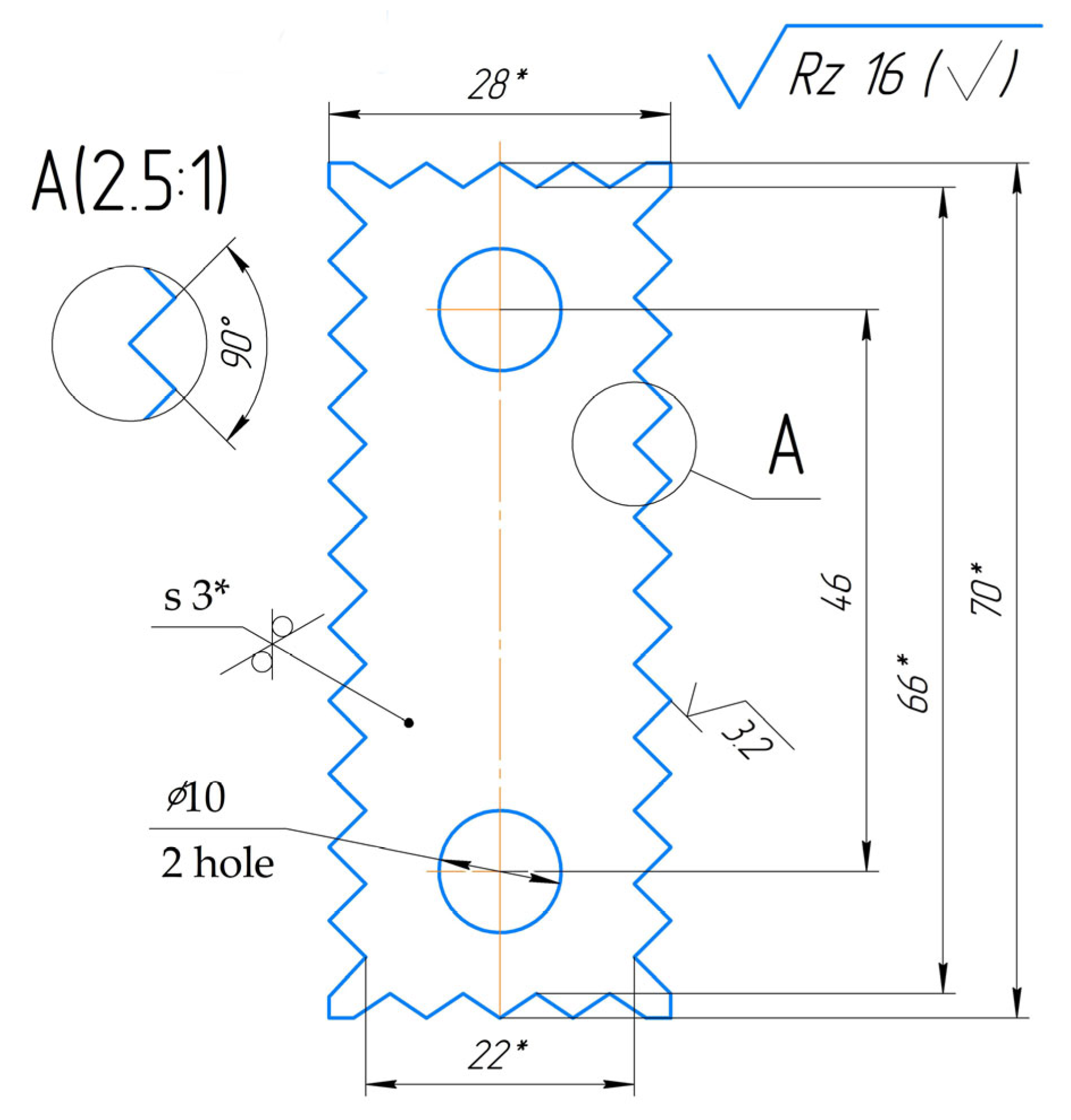
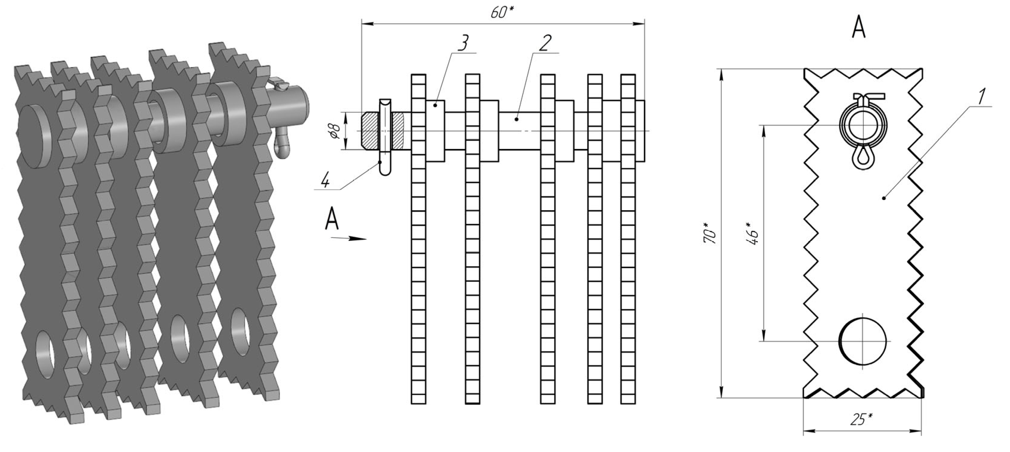
3.1. Theoretical Research on the Development of Four-Sided Serrated Hammers of the Hammer Mill of the Feed Preparation Device

To increase the efficiency of feed preparation processes, it is necessary to combine energy-intensive technological processes in one device. In this regard, we have developed a feed preparation device that combines the processes of grinding and mixing. The main thing here to be noted is a hammer crusher, in which fine grinding can be performed using the developed four-sided serrated hammers. At the same time, the hammers were developed by taking into account the desire for intensive crack formation in the crushed particles. To increase the likelihood of crack formation in the particles subject to destruction, we have put forward a hypothesis about the elimination of passive areas on the working surfaces of the impact organs of the crusher; i.e., the hammers take into account the increase in the efficiency of grinding. In our opinion, the elimination of passive areas can be facilitated by the formation of sharper surfaces on the impact areas of the hammers. At the same time, in some cases, these impact surfaces also serve as reflective surfaces against which chaotically bouncing particles of the crushed material are destroyed during the grinding process in the internal working area of the crusher. Therefore, based on the hypothesis put forward, from the design point of view, we have proposed serrated surfaces on all four planes of the hammer, which maximally utilizes the working surfaces of the hammer and simultaneously eliminates the previously existing passivity of the hammer. In this case, it can be clearly noted that the design parameters of the serrated surfaces are the step between the tops of adjacent serrations (t, mm), the height of the serrations (h, mm), the angle of inclination (α, °) and the sharpness of the serrations (oz, °).
It should be noted from the studies that grain waste particles are elastic and are subject to dry grinding. Each notch of the hammers cuts into the particles of the material being ground to a fraction of the notch height h, forming a split of a certain depth R. Therefore,
R ≤ h.
Ideally, a better ratio can be expected, where
R = h.
For the best impact-cutting effect, the serrations must have sharp blades, which is provided in our case structurally in the form of triangular serrations, i.e., the angle of inclination α and the sharpness of the serrations oz. In this case, the following condition is appropriate:
α m a x O z m a x .
However, from previously conducted scientific studies [20], it is preferable to provide hammers with an effective impact-cutting effect by means of cutting edges of a triangular shape with an angle of 2α = 90°. Therefore, based on previously obtained results, when developing the serrations of four-sided serrated hammers, we chose the inclination angle of adjacent sides of the serrations equal to 2α = 90°; i.e., the inclination angle of one side of the serration is equal to α = 45°. In addition, when choosing the inclination angle of the serrations, it is necessary to maintain a sufficient density of the width b of the hammer in accordance with the indicator of the reliability of its operation and the effectiveness of the blow provided by the required force. In this case, the width b and the length c of the hammer were approximately taken according to the following relations:
b = (0,4… 0,5)с.
с = 0.23 D,
where D—the diameter of the crusher working area.
The size of the notch affects the performance and is often characterized by the step between the tops of adjacent notches t. Meanwhile, it is worth noting that an increase in the step between the tops of adjacent notches t can lead to a decrease in the height of the notches h; most importantly, a decrease in the angle of inclination α; and, accordingly, a decrease in the sharpness of the notches oz, which are clearly demonstrated in Figure 1 under the simultaneous action of the following conditions
t m a x h m i n α m i n O z m i n .
Based on this, one should strive to reduce the step between the tops of adjacent serrations t. It becomes clear that increasing the height of the serrations h together with the angle of inclination α and the sharpness of the serrations oz is preferable, which is clearly demonstrated in Figure 2 with the simultaneous action of the following conditions
t m i n h m a x α m a x O z m a x .
Here, it becomes obvious that the increase in the step between the tops of adjacent serrations t leads to a decrease in the number of serrations, which significantly reduces the number of piercing cuts in grain waste particles. A decrease in the height of serrations h leads to a decrease in the angle of inclination α and the sharpness of serrations oz, which obviously reduces the depth of piercing blows and, consequently, the size of cracks in the crushed grain waste particles. A decrease in the angle of inclination α accordingly reduces the sharpness of serrations oz, which also reduces the depth of piercing blows B of the hammer. Therefore, we conducted special experiments with larger hammers, as shown in Figure 3.
In this case, the angle of inclination α and the sharpness of the serrations oz depend on the step between the vertices of adjacent serrations t and the height of the serrations h; i.e., it depends on two random variables, and the law of distribution of arguments is known.
In this case, the mathematical expectation of the function (x, y) from two random variables x and y for continuous random variables is as follows [35]:
M φ x , y = φ x , y   f x , y d x d y ,
where φ   x ,   y —the argument distribution function;
f   x ,   y —the argument distribution density.
The angle of inclination α and the sharpness of the serrations oz will be characterized by a unit vector with the same probability density and therefore the probability element:
f (t, h) dt dh,
where f (t, h)—the density distribution of the step between the vertices of adjacent serrations t and the height of serrations h.
In our theoretical studies, we found that the value of the average size of feed particles depends on the pitch between the serrations t of a four-sided serrated hammer. This is due to the fact that when grain waste is hit by a series of serrations, the smallest length of the grain waste particles will be equal to the distance between the faces of the serrations, i.e., equal to the pitch between the serrations t of a four-sided serrated hammer. To accurately determine the value of the average size of grain waste particles, we will consider the grain waste particles hitting two adjacent serrations on the hammer. Since four-sided serrated hammers have serrations with an impact-cutting slope, we will therefore consider the minimum size of the crushed particles to be equal to the distance between the faces of the serrations t of the hammer (Figure 4).
When hit by the hammer serrations, grain waste particles will be aligned on the plane of the striking surface of the four-sided serrated hammer. Therefore, the maximum length of grain waste particles when hit by hammers depends on the pitch of the serrations in the hammer t, i.e., the distance between the serrations of the hammer.
In this case, the crushing effect depends on the kinetic energy of the hammer and is also determined by the speed of the collisions of the crushed particles with the hammers and the collisions of particles with particles and particles with the internal parts of the crusher’s working area. For this, we can apply the theorem of the change in the kinetic energy of a mechanical system. In this case, we will use the concept of elementary work of force, where
dA = F·dS·cos α
The unfree motion of a material point is conveniently studied by the kinetostatics method based on the d’Alembert principle. This method is especially convenient when it is necessary to determine the reaction of the constraint for a given law of motion of the point and active forces.
Let us rewrite the differential equation of motion of a point in the following form:
F + R + (−ma) = 0.
This equality is the equation of motion of a material point, and it is written in the form of a condition of the equilibrium of forces. This is the method of kinetostatics for a point.
It is evident from Figure 4 that the sides of the notches of МD, EK, ED and NK have a certain length l each. It is necessary to determine the forces in each of the sides if concentrated masses m1 and m2 are located at points D and K and if angles МDE and EKN are equal to 2α. The acceleration of the masses m1 = ω12lcos α and m2 = ω22lcosα is directed horizontally to the side MEN. Accordingly, the force (−ma) is directed horizontally from the side MEN and is equal to m1ω12lcos α and m2ω22lcos α.
Thus, providing serrated surfaces on all four planes of the hammer will ensure the efficient design of a series of hammers mounted on the axes of the hammer crusher. It has been found that the size of the hammer serrations affects productivity. Based on this, one should strive to reduce the pitch between the tops of adjacent hammer serrations, which will accordingly increase the height of the serrations h together with the angle of inclination α and the sharpness of the serrations oz.

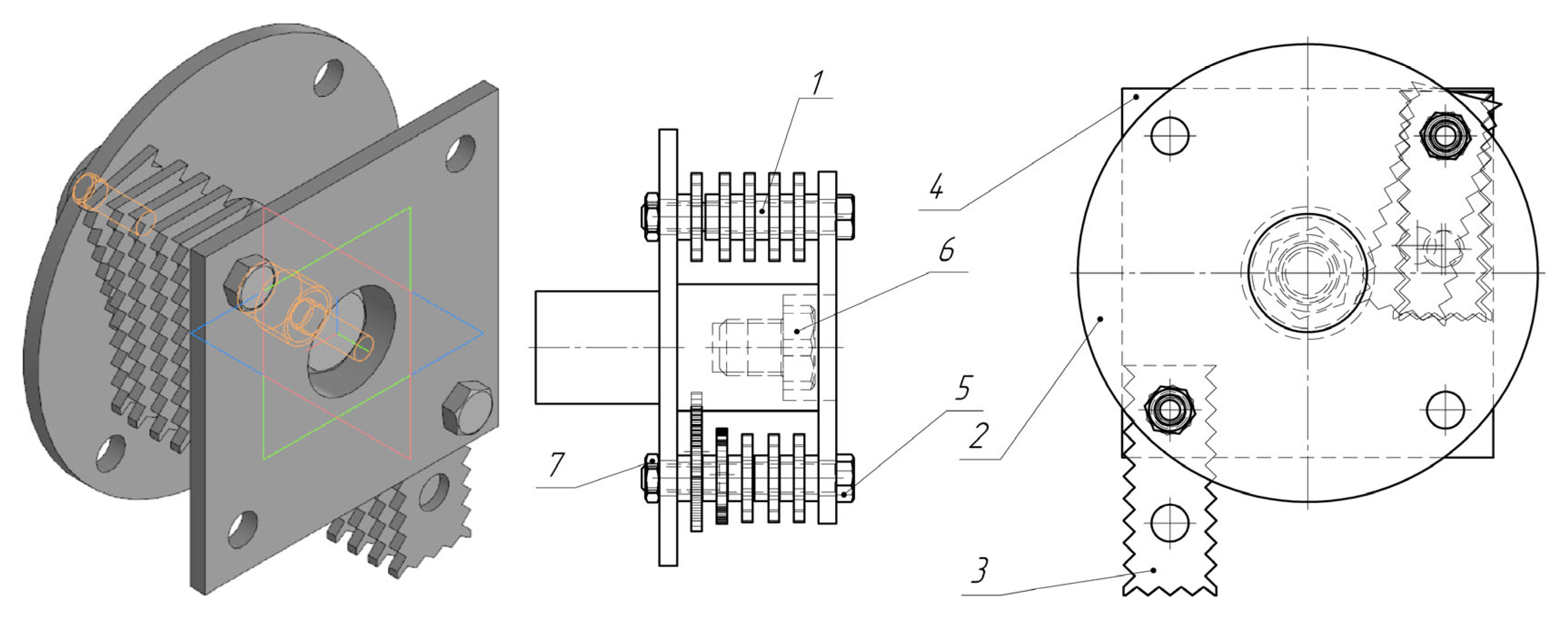
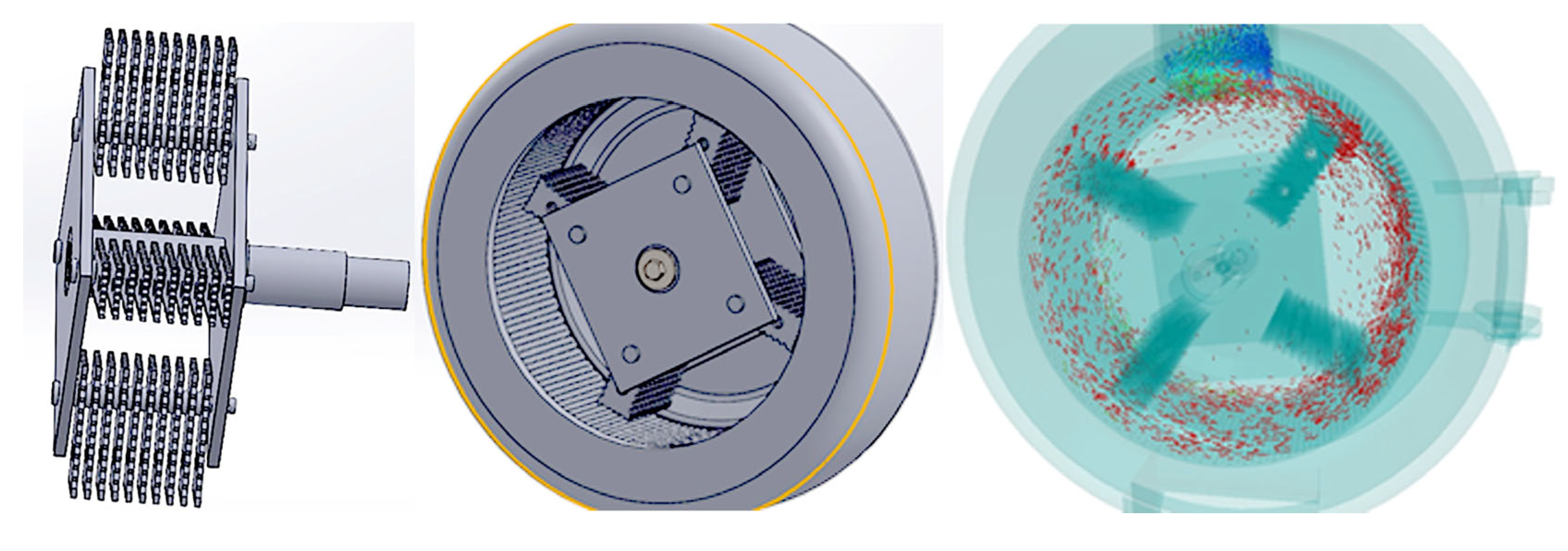
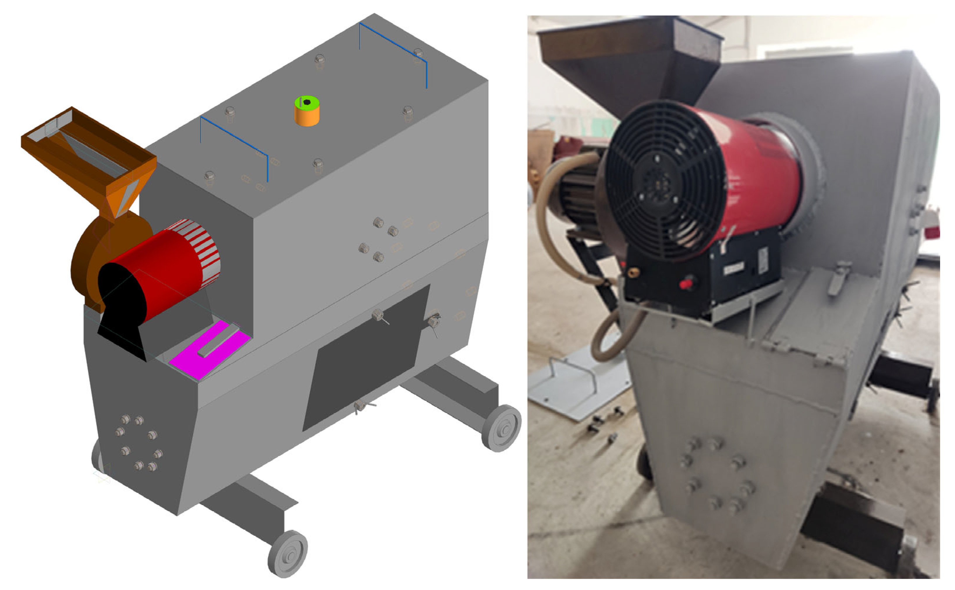
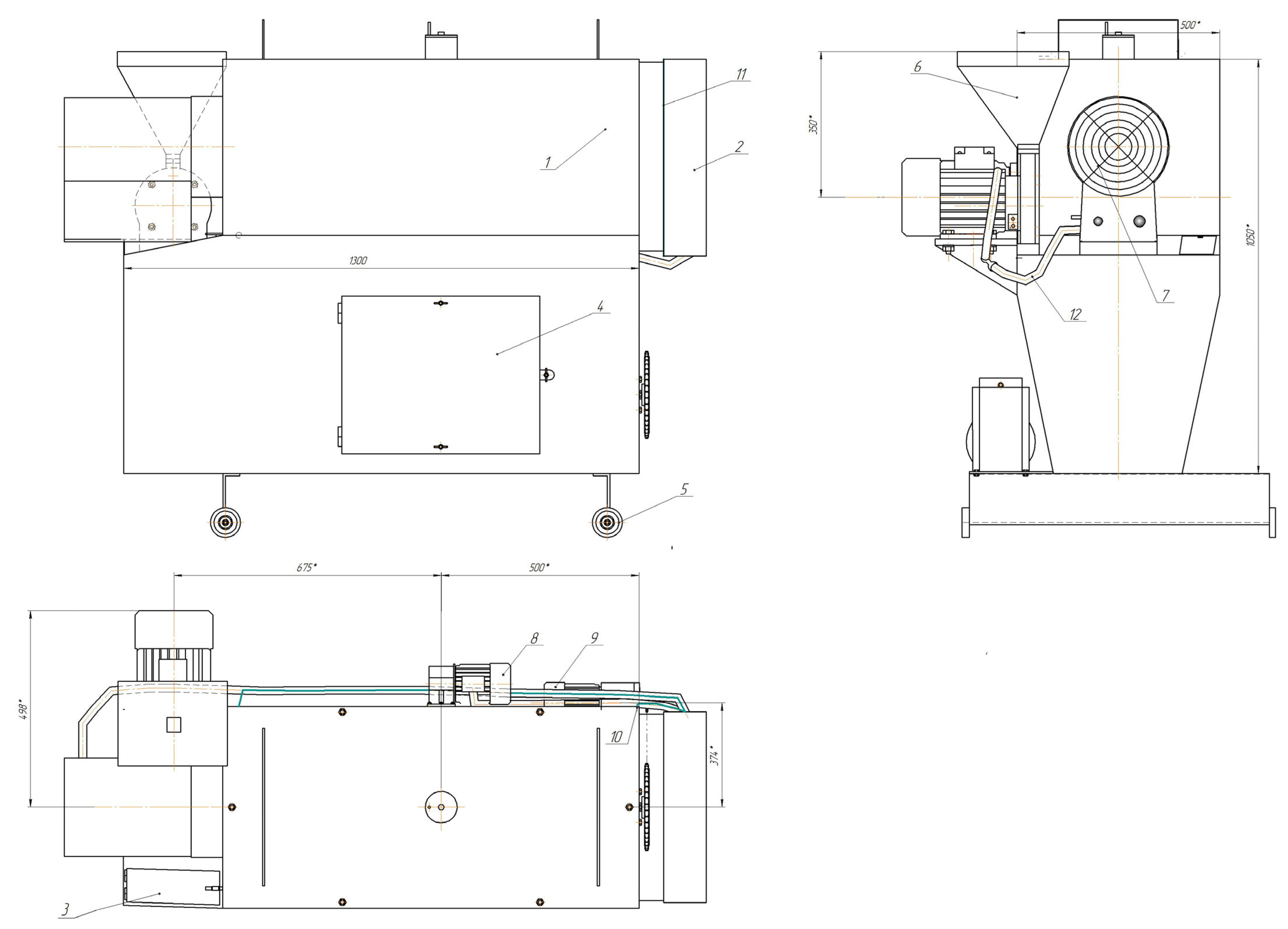
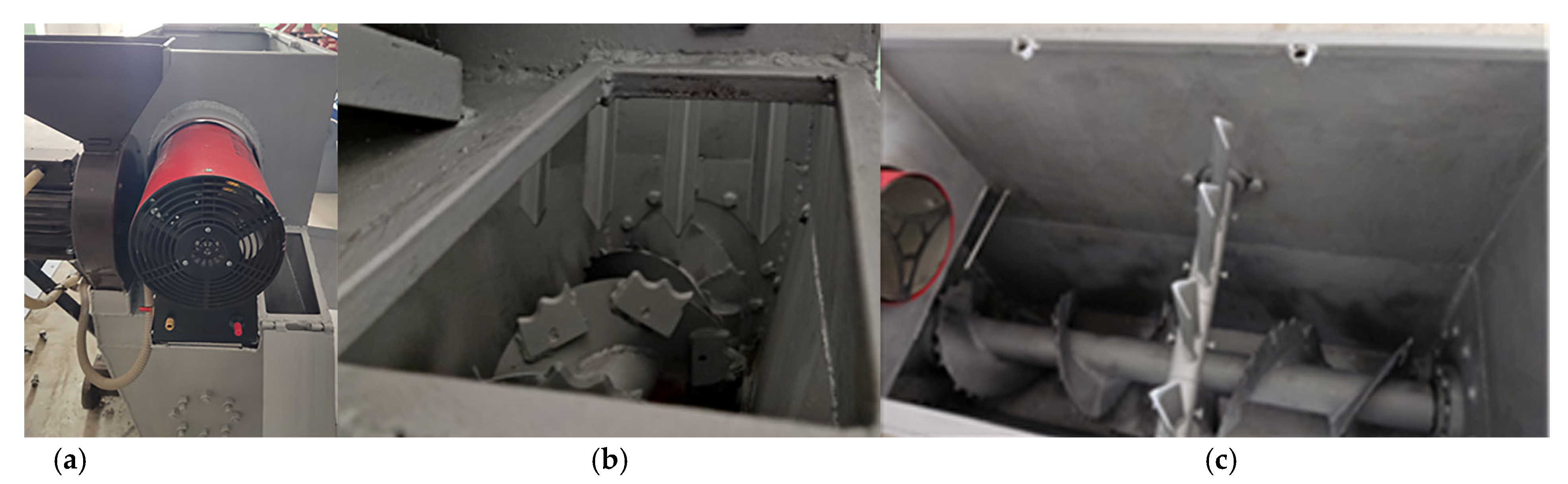
3.2. Design of a Forage Preparation Device with Four-Sided Serrated Hammers, an Auger and a Striking-Finger Shaft

The optimal way to prepare feed mixtures is with special technological devices. We have developed and designed a special feed preparation device, where the main working elements are four-sided serrated hammers for crushing and an auger with a striking-finger shaft for the optimal mixing of feed components. Figure 5 shows the developed four-sided serrated hammer, which is the main working element of the hammer crusher of the feed preparation device. Each of the four surfaces of the hammer has serrations.
It should also be noted that the presence of two replaceable hinge holes of the four-sided serrated hammers ensures an optimal impact angle on the crushed material and shock load cushioning. At the same time, all four serrated surfaces of the hammers have significant shear forces. Figure 6 shows a series of four-sided serrated hammers fixed on an axis.
Based on the hypothesis, we have developed a design and technological scheme of a rotor with two axes on four-sided serrated hammers (Figure 7). Figure 8 shows the 3D photographs of a rotor with four axes on the four-sided serrated hammers.
Figure 9 and Figure 10 shows the drawings of the developed feed preparation device.
In the hammer crusher (Figure 10), which is part of the developed feed preparation device, four-sided serrated hammers are installed, in which the pitch between the serrations is 4 mm; i.e., the distance between the faces of adjacent serrations in the hammer is equal to 4 mm. The four-sided serrated hammers are made of a sheet that is 3 mm thick.
Figure 11a shows the inlet pipe for grain waste through the hammer mill hopper and the inlet pipe for peas. Figure 11b shows the window of the inlet pipe for peas, where the knives on the screw and the impact fingers of the upper shaft, which are used to mix the feed mass, are visible. Figure 11c shows a top view of the mixing working area, where the crushed grain waste from the hammer mill and peas are fed.
In general, the feed preparation device with four-sided serrated hammers, an auger and the impact-finger shaft passed tests in idle mode and with the production of the feed mixture. The design of the feed preparation device provides a hammer crusher with developed four-sided serrated hammers and also an impact-finger shaft in combination with the operation of a spiral-knife auger for grinding and mixing. In addition, the feed preparation device has the ability to dry the feed mass, but in our case, the feed raw material was dry, and therefore, the heat gun was not used.

3.3. Results of Determining the Size of Crushed Grain Waste Particles and the Homogeneity of the Feed Mass Obtained in a Feed Preparation Device

As is known, the actual values of the grinding and mixing processes are determined by the results of experimental studies. Experiments were conducted to determine the quality of grinding grain waste. The grain waste was dry. The initial average size was 8 mm. The feedstock was fed through the hammer mill hopper by opening the valve. At the outlet of the hammer mill, a grate with 4 mm holes was installed. The average size of the crushed particles was determined via sieve analysis. Table 1 shows the results of the sieve analysis. In this case, the number of samples taken was three.
The capabilities of the feed preparation device allow for the preparation of various feed mixtures, and therefore, during the experimental work, after grinding in a hammer mill using four-sided serrated hammers, the crushed particles from the outlet pipe of the hammer mill immediately entered the working area via mixing using the feed preparation device. In the working area of mixing of the feed components, the process of mixing of feed components took place by means of the working bodies, i.e., the auger and the impact-finger shaft. Table 2, Table 3 and Table 4 present the results of laboratory studies on the homogeneity of the mixing of feed components.
σ = ( m s m k ) 2 n 1 = 262.703 10 1 = 5.403 ,
ʋ = σ 100 m s m = 5.403 100 40.41 = 13.37
O = 100% − 13.37% = 86.6%
σ = ( m s m k ) 2 n 1 = 168.649 10 1 = 4.329 ,
ʋ = σ 100 m s m = 4.329 100 33.902 = 12.769
O = 100% − 12.769% = 87.2%
σ = ( m s m k ) 2 n 1 = 155.369 10 1 = 4.155 ,
ʋ = σ 100 m s m = 4.155 100 33.423 = 12.431
O = 100% − 12.431% = 87.6%
Thus, the feed preparation device, including a hammer mill with four-sided serrated hammers, the auger and the impact-finger shaft, can be used in feed preparation shops and produces sufficiently crushed and uniformly mixed feed mass. The developed device is part of a feed production line, the originality of which is confirmed by the patent of the Republic of Kazakhstan for invention No. 36774 [36].

4. Conclusions

An analysis of modern scientific and technical information has revealed that the main trend in the development of feed preparation is the preparation of feed mixtures through the rational combination of technological processes of grinding and mixing in one device.
In the course of scientific research, a feed preparation device was developed, where the main working elements are four-sided serrated hammers for grinding and an auger with a striking-finger shaft for the optimal mixing of feed components. For the efficiency of grinding from a design point of view, we proposed serrated surfaces on all four planes of the hammer, which maximizes the use of the working surfaces of the hammer and simultaneously eliminates the previously existing passivity of the hammer. The design parameters of the serrated surfaces are the step between the tops of adjacent serrations (t, mm), the height of the serrations (h, mm), the angle of inclination (α, °) and the sharpness of the serrations (oz, °). It was found that the size of the serration affects the productivity, and it is often characterized by the step between the tops of adjacent serrations t. Based on this, it is necessary to strive to reduce the step between the tops of adjacent serrations t. It becomes clear that increasing the height of the serrations h, together with the angle of inclination α and the sharpness of the serrations oz, is preferable. All four serrated surfaces of the developed hammers have significant shear forces. However, it is worth noting the limitation of grinding meat and bone feed raw materials in a hammer mill, which must first be defatted, crushed and dehydrated.
As a result of the experimental studies, crushed particles of the feed from grain waste were obtained. It is clear from the results that after grinding grain waste in a hammer mill, additional grinding is not required, since a significant number of the crushed particles of grain waste were less than 1 mm in size (25.36–34.34%), the particle size was over 1 mm and less than 2 mm (35.09–44.22%), the particle size was over 2 mm and less than 3.55 mm (27.59–28.73%), and an insignificant number of particles had a size of more than 3.55 mm (0.99–2.98%). From the results of grinding grain waste in a hammer mill located in the upper part of the feed preparation device, it can be concluded that the crushed particles were of sufficient size for feeding agricultural birds and preparing compound feed.
As a result of the experimental studies of feed samples prepared using the developed feed preparation device, the following results were obtained for the homogeneity of mixing of grain waste and peas: 86.6% (after 2 min), 87.2% (after 4 min), and 87.6% (after 6 min). The obtained values of feed homogeneity showed sufficiently high homogeneity corresponding to the requirements. At the same time, it is worth noting that the study of the developed feed preparation device can be continued by taking into account the development of a new grate on the outlet pipe of the hammer mill to increase the efficiency of the ejection of crushed particles.
In general, the developed feed preparation device, including a hammer mill with four-sided serrated hammers, the auger and the impact-finger shaft, can be used in feed preparation shops and produces sufficiently crushed and uniformly mixed feed mass. Based on the research results, we plan to scale up the design of four-sided serrated hammers for other hammer mills and grinders.

Author Contributions

Conceptualization, R.I.; methodology, R.I.; software, A.G.; validation, A.G.; formal analysis, R.I.; investigation, R.I.; resources, R.I. and A.G.; data curation, R.I.; writing—original draft preparation, R.I.; writing—review and editing, R.I. and A.G.; visualization, A.G.; supervision, R.I.; project administration, R.I.; funding acquisition, R.I. All authors have read and agreed to the published version of the manuscript.

Funding

This research has been/was/is funded by the Science Committee of the Ministry of Science and Higher Education of the Republic of Kazakhstan (Grant No. AP19679802).

Data Availability Statement

The original contributions presented in this study are included in the article. Further inquiries can be directed to the corresponding authors.

Conflicts of Interest

The authors declare no conflicts of interest. The authors declare that they have no conflict of interest in relation to this research, whether financial, personal, authorship or otherwise, that could affect the research and its results presented in this paper.

References

  1. Iskakov, R.М.; Iskakova, A.M.; Nurushev, M.Z.; Khaimuldinova, A.K.; Karbayev, N.K. Method for the Production of Fat from Raw Materials and Animal Waste. J. Pure Appl. Microbiol. 2021, 15, 716–724. [Google Scholar] [CrossRef]
  2. Iskakov, R.М.; Mamirbaeva, I.K.; Gulyarenko, A.A.; Silaev, M.Y.; Gusev, A.S. Improved Hammers for Crushers in Feed Production. Russ. Eng. Res. 2022, 42, 987–992. [Google Scholar] [CrossRef]
  3. Abilzhanuly, T.; Iskakov, R.; Abilzhanov, D.; Gulyarenko, A.; Khan, V. Justification of Parameters of Impact-Spreading Finger Shaft for Grinder-Mixer-Dryer Using the Example of Eggshells. East. Eur. J. Enterp. Technol. 2024, 3, 33–44. [Google Scholar] [CrossRef]
  4. Krolczyk, J.B.; Rezwiakow, A.; Tukiendorf, M. Mixing of biomass and coal in a static mixer as an example of technological solutions involving implementation of renewable energy sources. Ecol. Chem. Eng. S 2014, 4, 685–696. [Google Scholar] [CrossRef]
  5. Mansour, W.; Melekhin, D.; Pasko, A. Continuous Production of Multicomponent Powder Mixtures. International Scientific Practical Conference Materials Science, Shape-Generating Technologies and Equipment. Серия книг MATEC Web Conf. 2020, 315, 04003. [Google Scholar] [CrossRef]
  6. Hastie, D.B. On the Difficulties of Sampling Bulk Powder Blends in Determining Segregation Propensity—A Case Study. Powder Technol. 2015, 286, 164–171. [Google Scholar] [CrossRef]
  7. Liu, B.Q.; Sun, N.; Jin, Z.J.; Zhang, Y.K.; Sunden, B. Numerical Investigation and Estimating Correlation of Micromixing Performance of Coaxial Mixers. Ind. Eng. Chem. Res. 2019, 58, 22376–22388. [Google Scholar] [CrossRef]
  8. Li, X.N.; Yang, L.; Guo, J.H.; Li, W.; Zhou, M.L.; Zhang, J.L. Micromixing Performance of the Teethed High Shear Mixer Under Semi-Batch Operation. Front. Chem. Sci. Eng. 2021, 16, 546–559. [Google Scholar] [CrossRef]
  9. Saensukjaroenphon, M.; Jones, C.K.; Fahrenholz, C.H.; Stark, C.R. The Effect of Extended Mix Times and Sample Preparation with Different Salt Particle Sizes on The Uniformity of Mix of a Corn-SBM Swine Diet. Trans. Asabe 2018, 61, 743–746. [Google Scholar] [CrossRef]
  10. Solongo, T.; Nyamgerel, B.; Baatarkhuu, D. Results of Optimazing the Technological Parameters of a Total Mixed Ratio (TMR) Machine. Inmateh-Agric. Eng. 2022, 67, 176–181. [Google Scholar] [CrossRef]
  11. Khmelovskyi, V.; Otchenashko, V.; Voloshyn, S.; Pinchevska, O. Providing Processes of Preparation and Distribution of Feed for Cattle on Animal Husbandry Farms. In Proceedings of the 19-th International Scientific Conference Engineering for Rural Development, Jelgava, Latvia, 20–22 May 2020; pp. 778–783. [Google Scholar] [CrossRef]
  12. Markochev, V.M.; Alymov, M.I. On the Brittle Fracture Theory by Ya. Frenkel and A. Griffith. Chebyshevskii Sb. 2017, 18, 381–393. [Google Scholar] [CrossRef]
  13. Bonet, J.; Gil, A.J. Mathematical Models of Supersonic and Intersonic Crack Propagation in Linear Elastodynamics. Int. J. Fract. 2021, 229, 55–75. [Google Scholar] [CrossRef]
  14. Kupchuk, I.M.; Solona, O.V.; Derevenko, I.A.; Tverdokhlib, I.V. Verification of the Mathematical Model of the Energy Consumption Drive for Vibrating Disc Crusher. Inmateh-Agric. Eng. 2018, 55, 113–120. Available online: https://www.researchgate.net/publication/328293822_Verification_of_the_mathematical_model_of_the_energy_consumption_drive_for_vibrating_disc_crusher (accessed on 1 January 2020).
  15. Savinyh, P.; Isupov, A.; Ivanov, I.; Ivanovs, S. Research in Сentrifugal Rotary Grinder of Forage Grain. Eng. Rural. Dev. 2021, 20, 205–211. [Google Scholar]
  16. Double Ended Hammer Mill Hammer. Available online: https://g3hammers.com/product/double-ended-hammer-mill-hammer/ (accessed on 10 April 2017).
  17. Bian, W.L.; Rong, S.F.; Zhu, Y.C.; Zhou, H.T. Research and Application of Dual Liquid Bimetal Composite Casting Hammer. Appl. Mech. Mater. 2012, 271–272, 268–271. [Google Scholar] [CrossRef]
  18. Zhang, J.; Feng, B.; Guo, L.; Kong, L.; Zhao, C.; Yu, X.; Luo, W.; Kan, Z. Performance test and Process Parameter Optimization of 9FF Type Square Bale Straw Crusher. Int. J. Agric. Biol. Eng. 2021, 14, 232–240. [Google Scholar] [CrossRef]
  19. Li, H.; Jiang, S.; Zeng, R.; Geng, J.; Niu, Z. Numerical Simulation and Analysis of the Airflow Field in the Crushing Chamber of the Hammer Mill. Acs Omega 2024, 9, 32674–32686. [Google Scholar] [CrossRef] [PubMed]
  20. Abilzhanuly, T.; Iskakov, R.; Abilzhanov, D.; Darkhan, O. Determination of the Average Size of Preliminary Grinded Wet Feed Particles in Hammer Grinders. East. Eur. J. Enterp. Technol. 2023, 1, 34–43. [Google Scholar] [CrossRef]
  21. Moiceanu, G.; Voicu, G.; Paraschiv, G.; Vladut, V.; Cardei, P.; Dinca, M. Relationships analysis between the grinding parameters of miscanthus giganteus stalks using a hammer mill. In Proceedings of the 47-th International Symposium on Agricultural Engineering, Opatija, Croatia, 5–7 March 2019; Kovacěv, I., Bilandžija, N., Eds.; University of Zagreb, Faculty of Agriculture: Zagreb, Croatia, 2019; pp. 399–407. [Google Scholar]
  22. Moiceanu, G.; Chitoiu, M.; Voicu, G.; Paraschiv, G.; Vladut, V.; Gageanu, I.; Dinca, M. Comparison between Miscanthus and willow energy consumption during grinding. In Proceedings of the 46-th International Symposium on Agricultural Engineering, Opatija, Croatia, 27 February–1 March 2018; University of Zagreb, Faculty of Agriculture: Opatija, Croatia, 2018; pp. 369–378. [Google Scholar]
  23. Viňáš, J.; Brezinová, J.; Brezina, J.; Hermel, P. Innovation of Biomass Crusher by Application of Hardfacing Layers. Metals 2021, 11, 1283. [Google Scholar] [CrossRef]
  24. Wang, D.; Tian, H.; Zhang, T.; He, C.; Liu, F. DEM Simulation and Experiment of Corn Grain Grinding Process. Eng. Agric. 2021, 41, 559–566. [Google Scholar] [CrossRef]
  25. Mou, X.; Wan, F.; Wu, J.; Luo, Q.; Xin, S.; Ma, G.; Zhou, X.; Huang, X.; Peng, L. Simulation Analysis and Multiobjective Optimization of Pulverization Process of Seed-Used Watermelon Peel Pulverizer Based on EDEM. Agriculture 2024, 14, 308. [Google Scholar] [CrossRef]
  26. Soonnam, B. The Device of the Mixing Part of the Grinder of Food Waste. Kazakhstan Patent KR10-1026463, 2011. [Google Scholar]
  27. Awasthi, K.S.; Gopireddy, S.R.; Scherließ, R.; Urbanetz, N.A. Numerical Investigation of Screw Design Influence on Screw Feeding in a Roller Compactor. In Proceedings of the 6th International Conference on Particle-Based Methods. Fundamentals and Applications, Particles, Barcelona, Spain, 28–30 October 2019; pp. 444–455. [Google Scholar]
  28. Vasilenko, V.N.; Frolova, L.N.; Mikhailova, N.A.; Dragan, I.V. Innovative Technology to Obtain Forage Flour from Keratin-containing Waste by Extrusion. IOP Conf. Ser. Earth Environ. Sci. 2021, 640, 022010. [Google Scholar] [CrossRef]
  29. Deng, R.; Tan, Y.Q.; Zhang, H.; Xiao, X.W.; Jiang, S.Q. Experimental and DEM Studies on the Transition of Axial Segregation in a Truck Mixer. Powder Technol. 2017, 314, 148–163. [Google Scholar] [CrossRef]
  30. Kirchner, A.; Feil, A.; Colovic, R.; Vukmirovic, D.; Levic, J. Discontinuous Addition of Small Volumes of Liquids in an Intensive Mixer to Animal Supplement Feed with Different Particle Size Distributions. Powder Technol. 2013, 239, 358–365. [Google Scholar] [CrossRef]
  31. Sin, T.Y.; Asnawi, S.; Norashikin, A.A.; Mohd, S.A.; Yus, A.Y.; Farah, S.T. The Influence of Operational Parameters and Feed Preparation in a Convective Batch Ribbon Powder Mixer. Drug Des. Dev. Ther. 2011, 5, 465–469. [Google Scholar]
  32. GOST 2.601-2006; Unified System of Design Documentation. Operational Documents. Standartinform: Moscow, Russia, 2006; 36p. (In Russian)
  33. Gernet, M.M. Course in Theoretical Mechanics; Murphy Higher School: Mobile, Alabama, 1973; 402p. (In Russian) [Google Scholar]
  34. ST RK ISO 4254-1-2011; Agricultural Machinery. Safety. Part 1. General Requirements. Committee for Technical Regulation and Metrology: Astana, Kazakhstan, 2011; 39p. (In Russian)
  35. Ventzel, E.S. Probability Theory: A Textbook for Universities, 7th ed.; Murphy Higher School: Mobile, Alabama, 2001; 575p. (In Russian) [Google Scholar]
  36. Iskakov, R.M. Feed Production Line. Application reg. number 2023/0026.1, 17 January 2023. Patent for invention of the Republic of Kazakhstan No. 36774 “Feed production line”, 19 July 2024. (In Russian). [Google Scholar]
Figure 1. Dependence of the decrease in the height of the serrations h on the increase in the step between the tops of adjacent serrations t.
Agriengineering 07 00183 g001
Figure 2. Dependence of the increase in the step between the vertices of adjacent serrations t with the same serration height h.
Agriengineering 07 00183 g002
Figure 3. Dependence of the inclination angle of the hammer teeth α on the depth of the hammer’s piercing blows B (dimensions of the hammer: a length of 100 and a width of 50).
Agriengineering 07 00183 g003
Figure 4. Schematic diagram of the arrangement of a grain waste particle of length C between the edges of the notches (the pitch between the tops of adjacent notches t) of a hammer. A—width of the crushed particle, measured in mm; C—length of the crushed particle, measured in mm; h—notch height, measured in mm; t—step between the tops of adjacent notches, measured in mm; B—depth of notch penetration into the crushed particle, measured in mm; α1, α2, 2α—inclination angles of notch sides, measured in °; P—normal pressure on notch sides, measured in N/mm2; Рv—vertical force creating a crack plane, measured in N; Рg—horizontal force pushing apart separated halves of the crushed particle in directions perpendicular to the rupture plane, measured in mm; Yz—notch force, measured in N; FT—friction force, measured in N.
Agriengineering 07 00183 g004
Figure 5. Four-sided serrated hammer.
Agriengineering 07 00183 g005
Figure 6. Series of four-sided serrated hammers on an axis. 1—four-sided serrated hammer; 2—axle; 3—washer; 4—cotter pin.
Agriengineering 07 00183 g006
Figure 7. Rotor with two axes on four-sided serrated hammers. 1—bushing; 2—disk; 3—four-sided serrated hammer; 4—plate; 5—axle; 6—bolt connection; 7—cotter pin.
Agriengineering 07 00183 g007
Figure 8. Rotor with four axes on four-sided serrated hammers.
Agriengineering 07 00183 g008
Figure 9. Developed feed preparation device.
Agriengineering 07 00183 g009
Figure 10. Drawings of the developed feed preparation device. 1—feed preparation device housing; 2—control cabinet; 3—input hopper to the knife grinding and mixing zone; 4—unloading hatch for finished feed; 5—wheel for moving the feed preparation device; 6—hammer crusher; 7—heat gun; 8 and 9—gear motors; 10—belt drive; 11—wall for mounting the control cabinet; 12—cable in a corrugated pipe in case of connecting a heat gun.
Agriengineering 07 00183 g010
Figure 11. Photographs of the parts and units of the developed feed preparation device. (a)—inlet pipe for grain waste, located in the bunker of the hammer mill and inlet pipe for peas; (b)—inlet pipe for peas; (c)—top view of the working mixing area.
Agriengineering 07 00183 g011
Table 1. Sieve analysis data for grain waste.
Sample No.Size of Sieve Holes, mmResidue Mass, gResidue on Sieve, %
13.550.62.98
25.5627.59
17.0735.09
bottom6.9234.34
Total mass20.15100
23.550.20.99
25.6728.14
18.743.18
bottom5.5827.69
Total mass20.15100
33.550.341.69
25.7928.73
18.9144.22
bottom5.1125.36
Total mass20.15100
Table 2. Data for determining the homogeneity of the masses of grain waste and pea samples after t1 = 2 min of mixing.
Sample No.ms, Mass of Average Sample with Cont.Com., gmn,
Net Weight, g
mк,
Mass of Control Component, g
msm,
Average Sample Weight
(msm − mк)(msm − mк)2
1445.9419.826.122.70600
2413.1378.13533.80700
3463.7420.143.637.90400
4388.234543.245.7312.5316.406
5406.3371.934.433.78200
6500.91447.5153.443.5800
7403.7362.74141.2840.2840.081
8325.7289.835.945.2429.34287.273
9295.55262.553345.90412.904166.513
10407.3354.752.654.1591.5592.430
average = 365.216average = 39.82average = 40.41 Sum = 262.703
Table 3. Data for determining the homogeneity of the masses of grain waste and pea samples after t2 = 4 min of mixing.
Sample No.ms, Mass of Average Sample with Cont.Com., gmn,
Net Weight, g
mк,
Mass of Control Component, g
msm,
Average Sample Weight
(msm − mк)(msm − mк)2
1321.32291.729.6238.4718.85178.34
2395.79358.5137.2839.3972.1174.482
3568.4531.337.126.45600
4411.4375.835.635.890.290.084
5325.5301.424.130.2946.19438.366
6430.8399.83129.37700
7455.36421.7333.6330.21200
8491.04449.7541.2934.78200
9371.9337.93438.1224.12216.991
10351.3320.830.536.025.5230.47
average = 378.869average = 12.858average = 33.902 Sum = 168.649
Table 4. Data for determining the homogeneity of the masses of grain waste and pea samples after t3 = 6 min of mixing.
Sample No.ms, Mass of Average Sample With Cont.Com., gmn,
Net Weight, g
mк,
Mass of Control Component, g
msm,
Average Sample Weight
(msm − mк)(msm − mк)2
1354.09322.0532.0425.23900
2344.09305.2938.832.24200
3381.35345.4935.8626.33100
4336.17296.2239.9534.21400
5281.96235.7346.2349.7513.52112.397
6298.9246.8652.0453.4791.4392.071
7255.48229.6125.8728.5832.7137.360
8113.25106.25716.7139.71394.342
9251.7217.1334.5740.3905.8233.872
10257.21232.2324.9827.2882.3085.327
average = 253.686average = 33.734average = 33.423 Sum = 155.369
Disclaimer/Publisher’s Note: The statements, opinions and data contained in all publications are solely those of the individual author(s) and contributor(s) and not of MDPI and/or the editor(s). MDPI and/or the editor(s) disclaim responsibility for any injury to people or property resulting from any ideas, methods, instructions or products referred to in the content.

