Article

Modification and Performance Evaluation of a Biomass Pelleting Machine

by
Simeon Olatayo Jekayinfa
1,*,
Folorunso Adegboyega Ola
1,
Fatai Bukola Akande
1,
Mutairu Abiola Adesokan
2 and
Ibrahim Akinola Abdulsalam
1
1
Department of Agricultural Engineering, Ladoke Akintola University of Technology, Ogbomoso 210214, Nigeria
2
Cocoa Research Institute of Nigeria, Ibadan 200285, Nigeria
*
Author to whom correspondence should be addressed.
AgriEngineering 2024, 6(3), 2214-2228; https://doi.org/10.3390/agriengineering6030130
Submission received: 17 June 2024 / Revised: 11 July 2024 / Accepted: 11 July 2024 / Published: 16 July 2024
(This article belongs to the Special Issue Research Progress of Agricultural Machinery Testing)

Abstract

:
The use of biomass as a source of energy has been identified to be energy intensive, involving high handling costs. However, pelletization reduces the bulk density of biomass, thereby reducing the handling costs and enhancing ease of use. This study modified and evaluated an existing hand-operated fish feed pelleting machine. The parts of the machine that were redesigned were the hopper and the power transmission unit. Corncob was used to evaluate the modified machine using the die hole diameter (5, 6 and 7 mm) and the binder quantity (0, 2.5 and 5 wt%) as factors. The average results obtained for machine efficiency, throughput, pellet length and bulk density were 58.83%, 4.24 kg/h, 15.51 mm and 0.160 g/cm3, respectively. The die hole diameter had a significant effect on the pellet length only. The binder quantity had a significant effect on machine efficiency, throughput and pellet length. Machine efficiency and throughput decreased as the quantity of binder increased, and the pellet length increased with the increasing quantity of binder.

1. Introduction

Biomass as an alternative energy source provides substantial socio-economic and environmental benefits for its high availability and carbon-neutral nature [1]. The use of fossil fuels and deforestation are the major contributors to climate change. Biomass is a term for all organic materials that stem from plants, including residues from wood and agro-processing operations that are discarded as waste [2]. These residues have been highly promoted to be used in various heating systems during the past decades [3,4]. The process of producing solid biofuel from biomass can help in the waste management of agro-residues in a productive way. Densification involves the compression of biomass residues in order to obtain dense fuels with homogenous size and improves its handling characteristics [3]. Bailing, briquetting, extrusion and pelletization are a few of the different biomass densification processes that are used globally [5]. The homogenous size of pellets facilitates automatic or semi-automatic treatment and thus, addressing the disadvantages of the traditional use of biomass [6,7] and the stress involved in the utilization of other methods of densification. While definitions vary, most researchers used the term “Pellet” to describe densified products with diameters ranging between 3 and 27 mm and lengths ranging from 3 to 31 mm [8,9,10].
Domestically, densified products can be used in small stoves to efficiently reduce the cost of cooking [11]. They can replace coal in certain applications, such as small-scale power plants, broilers and many industrial applications. Rising demands for solid biomass fuel and problems ranging from health, economic, environmental and climate change [12] have geared much research into the conversion of agricultural residues into feedstock for solid biofuel products [13] and also into improving the quality of these materials [14]. Farm incomes have been improved through trees planted on agricultural land to produce biomass feedstock sustainably for the production of solid biofuel [15]. Densification has also been incorporated to increase the quality of animal feeds. Orisaleye et at. [16] studied the effect of preconditioning and die thickness on livestock feed pellets and found that using starch as a preconditioner and increasing die thickness improved the durability of pelleted feeds. Several studies [17,18,19] have produced densified biofuel from rice bran, corncob and poplar wood under different operating conditions. The conversion of various biomasses, including woods, composts, grasses, straws, crop residues and torrefied materials [20,21,22,23], into solid fuels has also been studied, with a focus on the impact of feedstock characteristics on pellet quality [24] and on extension products from other biomass conversion processes. A study by Jekayinfa et al. [25], analyzing biogas and methane yields, concluded that treating particles to an ideal size of 4 mm yields methane and biogas.
Samuelsson et al. [26] report that the final quality of pellets varies depending on the raw material properties and the manufacturing process. The quality parameters of densified products include moisture content, unit and bulk densities, durability index, compressive strength, percent fines and energy value [4]. Orisaleye et al. [4] studied the effect of pressure, temperature, particle sizes and holding time on the water resistance properties of corncob briquettes. Their results showed that increasing the die temperature (from 90 to 120 °C) and holding time (from 7.5 to 15 min) increased the water resistance of the briquettes. Jekayinfa et al. [17] studied the effects of die geometry and binder addition on the quality of rice bran pellets. Their results showed that binder quantity and geometry significantly affect the bulk density of rice bran pellets. Although the inorganic and organic components of the different raw materials cannot be modified, certain variables dependent on the pelletization process can be controlled to optimize the production efficiency and enhance the quality of the finished product. The most studied aspect of pelletization is the evaluation of the operating conditions to improve the process and obtain high-quality pellets [27]. This study modified an existing hand-operated fish feed pelletizing machine for use in the production of biomass pellets.
The novelty of the presented pelleting machine lies in its specific modifications, aimed at improving the pelletization process for biomass materials. The redesigned hopper and power transmission unit enhance the machine’s adaptability and efficiency in handling different biomass types, such as corncob. These modifications address the challenges of high bulk density and handling costs associated with biomass, providing a practical solution for small-scale biomass pellet production. By optimizing the die hole diameter and binder quantity, the machine achieves better performance metrics, demonstrating significant improvements over traditional hand-operated pelleting machines.

2. Materials and Methods

2.1. Description of the Existing Fish Feed Pelletizing Machines

The existing hand-operated fish feed pelletizer is designed for small scale commercial operation. The pelletizing unit consists of a compression chamber, an auger, a die plate and a hand-driven pulley. The parts are as shown in Figure 1.
a.
Compression Chamber
The compression chamber or barrel (Figure 1A) is the housing where the pressure generated is mounted on the material been pelletized. It is made of cast iron, 10 mm in thickness, with an internal diameter of 80 mm and 200 mm in length. It has a hopper opening of 90 mm in diameter at the top, which serves as an inlet for materials to be pelletized and as support for the attachment of the barrel to the frame of the machine.
b.
Auger
The auger, or screw shaft (Figure 1B), conveys material from the bottom of the hopper inside the barrel to the die plate. It is made from cast iron and is 200 mm in length and 25 mm in diameter, with a nominal diameter of 70 mm, a flight of 22.5 mm and a pitch of 50 mm. The auger has a clearance of 10 mm between the flight of the auger and the wall of the compression chamber.
c.
Die Plate
The die plate (Figure 1C) serves as the back wall for retaining the pressure exerted by the auger, while the perforations on the plate or die holes allow the compressed mash to be forced out of the barrel to form pellets. The die plate is made of a mild steel plate, 100 mm in diameter and a thickness of 6 mm. The die plate contains 48 cylindrical die holes of 6 mm in diameter each, bored into the plate. It also features a keyway cut on its edge, which fits with a protruding key on the body of the compression chamber. This design prevents the die plate from rotating with the auger and also prevents relative motion between the die plate and compression chamber wall.

2.2. Design of Other Components

The other component parts of the modified machine, which were designed and fabricated for incorporation with the pelletizing unit are the hopper, the power transmission unit (belt drive) and the frame.

2.2.1. Design of Hopper Extension

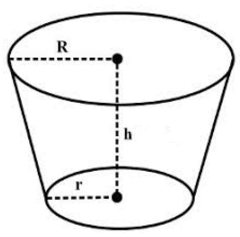
The hopper extension (Figure 2) was designed in the form of a cone frustum to allow the hopper extension to fit into the opening on the compression chamber of the pelleting unit. It has a top radius (R) of 435 mm, a base radius (r) of 90 mm and a height (h) of 280 mm. The base diameter was selected to allow it to fit into the chamber opening and slant at 60° angle of repose for fibrous non-free-flowing materials [28]. The volume of the hopper was calculated to be 0.0173 m3 using Equation (1) [29] for the volume of a cone frustum. Thus,
V = π h 3 R 2 + R r + r 2 ,

2.2.2. Power Required to Drive the Screw Conveyor

The power required to drive the machine was evaluated using Equation (2) [30], as presented by Singh [30].
P = Q L W 0 + sin β 3600 η ,
where
P = power required to drive the machine, kW;
Q = capacity of screw conveyor, kg/h;
L = length of screw conveyor = 200 mm (measured);
Wo = material factor = 2.5;
β = angle of inclination of screw to the horizontal, 0° (horizontal screw conveyor) [30];
η = efficiency of transmission = 0.92.
The capacity of the screw conveyor, Q, is calculated from Equation (3) [30] as 18.09 kg/h. From Equation (2), the power required, P, is calculated to be 2.73 kW. Recall that 1 hp is equal to 746 W, 2.73 kW is equivalent to 3.76 hp. Therefore, a 4 hp electric motor was selected.
Q = 150 π D 2 s n φ ρ C ,
where
D = nominal diameter of the screw conveyor = 80 mm (measured);
s = pitch of screw conveyor = 0.08 m (for standard screw pitch, S = D) mm;
n = speed of rotation of screw = 250 rpm [31];
φ = loading efficiency = 0.25;
ρ = density of material = 1200 kg/m3 [32];
C = inclination factor =1 (for horizontal conveyors) [30].

2.2.3. Design of Belt Drive System for Power Transmission

(a)
Speed of driven pulley
A v-belt drive system was designed for the machine and was powered by a 4 hp electric motor with a rated speed of 1400 rpm and a driving motor pulley of 100 mm. The pelleting unit has a driven screw conveyor pulley diameter of 300 mm. The speed of the driven pulley is calculated from the velocity ratio of the belt drive, using Equation (4) [33], as 466 rpm.
N 1 N 2 = d 2 d 1 ,
where
N1 = speed of motor pulley, rpm (1400 rpm);
N2 = speed of screw pulley, rpm;
d1 = diameter of motor pulley, mm (100 mm);
d2 = diameter of screw pulley, mm (300).
According to the IS:2494-1974 [34] standard, a type-A belt was selected for the machine, with the following characteristics:
a.
Power range = 0.7–3.5 kW;
b.
Top width (b) = 0.013 m;
c.
Thickness (t) = 0.008 m;
d.
Cross sectional area= b × t = 0.000104 m2;
e.
Coefficient of friction = 0.25;
f.
Density of rubber belt = 1000 kg/m3;
g.
Permissible stress = 2.8 MPa.
(b)
Belt velocity
The velocity, v, of the belt is calculated from Equation (5) [33] as 7.33 m/s.
V = π d 1 N 1 60 ,
where
V = velocity of the belt, ms−1;
d1 and N1 are as defined in Equation (4).
(c)
Centrifugal tension of belt
Centrifugal tension of the belt was calculated from Equation (6) [33]:
T c = m v 2 ,
where
Tc = centrifugal tension, N;
m = mass per unit length of belt, kg;
v = velocity of belt = 7.33 m/s (form Equation (5)).
Mass of belt per unit length is calculated from Equation (7) as 0.104 kg, and centrifugal tension, Tc, from Equation (6) is 5.59 N.
m a s s = A × l × ρ ,
where
A= belt cross sectional area = 0.000104 m2 [34];
l = unit length of belt (m) = 1.00 m;
ρ = density of belt material = 1000 kg/m3 [34].
(d)
Tension in belt
Tension in the tight side of the belt is calculated from Equation (8):
T 1 = T T c ,
where
T1 = tension in the tight side of the belt, N;
T = maximum tension in belt, N.
However, the maximum tension in the belt is calculated as 29.12 N from Equation (9) [33]. From Equation (8), the tension in tight side of belt is 23.53 N.
T = σ × A ,
where
σ = permissible stress, 2.8 MPa;
A = cross sectional area, 0.000104 m2.
The tension in the slack side of the belt is calculated from Equation (10) [33].
2.3 log T 1 T 2 = μ · θ csc β ,
where
T2 = tension in slack side of belt (N);
µ = coefficient of friction, 0.25;
θ = angle of contact, rad;
β = groove angle of belt, 16° [34]
The angle of contact, θ , is calculated from Equation (11) [33].
θ = 180 2 α ,
where
α = angle of lap.
α is calculated using Equation (12), thus
sin α = d 2 d 1 2 C ,
where
d1 = diameter of driving pulley, 0.1 m;
d2 = diameter of driven pulley, 0.466 m;
C = center distance between the two pulleys, m.
The center distance between the two pulleys, C, is calculated, using Equation (13), as 0.698 m (approximately 700 mm):
C = 2 d 2 d 1 + d 2 1 2 ,
where
d1 = diameter of driving pulley = 0.1 m;
d2 = diameter of driven pulley = 0.466 m;
C = center distance between pulleys, (mm).
Then, the center distance between the two pulley is calculated.
From Equation (12), the angle of lap, α, is 14.35°, the angle of contact from Equation (11) is 2.64 rad and the tension in the slack side of belt from Equation (10) is 13.5 N.
(e)
Power transmitted by belt
The power transmitted by the belt is calculated using Equation (14) as 162.58 Nm/s,
P = T 1 T 2 v ,
where
P = power transmitted by belt, Nm/s;
T1 = tension in the tight side of belt, 23.53 N;
T2 = tension in the slack side of belt, 1.35 N;
v = velocity of belt, 7.33 m/s.
(f)
Torque transmitted by belt
The torque in the driven pulley shaft is calculated as 3.33 Nm from Equation (15) [33]
T = P × 60 2 π N 2 ,
where
T = torque transmitted by the belt, Nm;
N2 = speed of driven pulley, 466 rpm;
P = power transmitted by belt, 162.58 W.

2.3. Fabrication and Assemblage of the Pelleting Machine

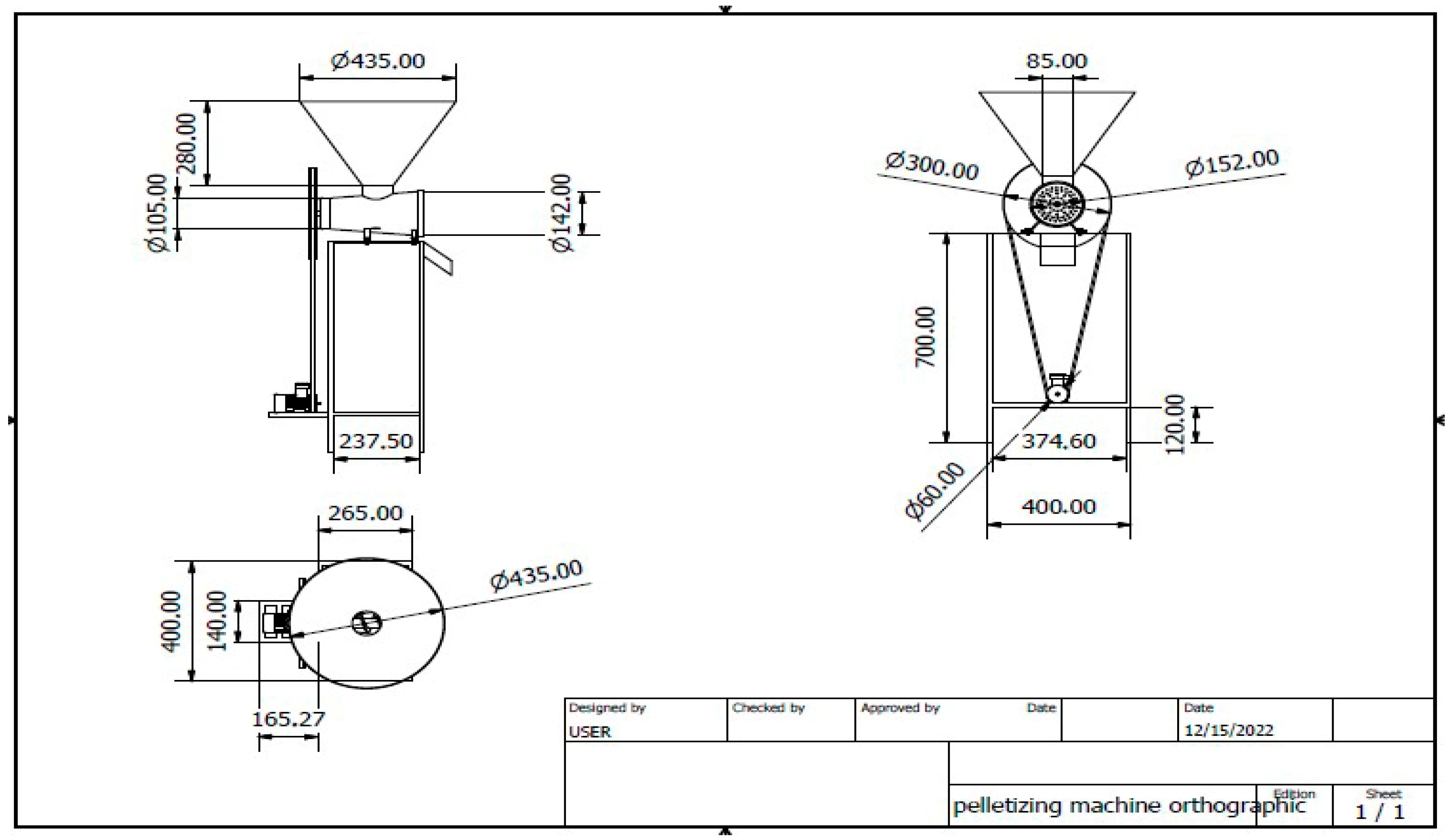
The pelleting machine comprises the frame support, the electric motor support, the hopper and the pelletizing unit. The frame and electric motor supports were fabricated from 2 mm angle iron. The rectangular frame is 400 × 160 × 700 mm, while the electric motor support of 415 × 200 mm was welded to the back of the frame at a height of 200 mm from the ground so that the center distance between the motor support and the screw shaft of 700 mm can be adjusted for belt tension. The various desired sizes were marked and cut out using a metal hack saw, and the component parts were welded together using an electric welding machine and electrode. The hopper of the machine was fabricated from a steel plate of 1 mm thickness. The shape of the hopper was marked out in the form of a trapezium, and its two ends folded and welded together to form the described shape of a truncated cone frustum. After the fabrication, the pelleting unit was mounted to the top of the frame and bolted with the use of four (4) size-13 bolts, and the hopper was bolted with three (3) size-12 bolts to the opening of the pelleting unit compression chamber, while the electric motor was also bolted to the motor support using four (4) size-12 bolts. The frame was scrubbed and painted with green paint to avoid rusting. The belt size needed as calculated was procured and fitted to the machine. Figure 3 and Figure 4 show the first angle orthographic projection and the exploded view, respectively, of the fabricated pelleting machine. The bill of engineering measurement and evaluation, detailing the various parts, their price and the cost of fabrication of the machine, is presented in Table 1.

2.4. Experimental Procedure

2.4.1. Feedstock Collection and Preparation

a. 
Corncob
After shelling, corncobs were collected from a private farm in Ogbomoso, Oyo State, Southwest Nigeria. The collected corncobs were crushed using a hammer mill and sieved using a 3 mm mesh size sieve. The materials that passed through the sieve were retained for the experiment, and the larger particle sizes were discarded. The moisture content (MC) of the feedstock was determined to be 9.85% (wb) using the oven dry method of ASTM E871 [35] standard. A known mass of sample (Wi) was dried in an oven at 103 ± 1 °C until three consecutive weights (Wf) of the sample were equal. The percent moisture in the analysis sample was calculated using Equation (16) [36].
M C = W i W f W i × 100 ,
b. 
Preparation of binder (cassava starch)
Raw cassava starch was purchased from a local starch processor. A smooth paste was made with 1 g of starch, by mixing it with 5 mL of distilled water. Thereafter, 100 mL of boiling water was poured into the starch paste and stirred until a thick starch gel was formed. This was cooled to room temperature before being blended with the milled corn cobs.
c. 
Mixing of corncobs with binder (feedstock mixture)
The European standard EN 14961-2 [37] allows a maximum content of 2% binder for woody pellets. For non-woody pellets, EN 14961-6 [38] specifies that there is no limitation to binder content. In this study, the quantities of binder used were in the ratios of 0.0, 2.5 and 5.0 wt% of binder to corncobs. The 0.0 wt% served as control, and the 2.5 and 5.0 wt% binders were mixed manually with the feedstock materials until a consistent mixture was obtained.

2.4.2. Performance Evaluation Procedure

The modified pelleting machine was evaluated for its efficiency and throughput capacity using the corncob as feedstock and cassava starch as a binder. For the pelleting operations, the machine was first connected to a power source and started. Then, known weights of the feedstock mixture were fed through the hopper of the machine, and the machine was allowed to run until the prepared products (pellets) stopped flowing out through the collecting point of the machine. The time required for each pelleting operation was taken using a stopwatch and recorded.
The weight (kg) of material fed into the machine is regarded as the input quantity, and the weight of pellets at the collection point is the quantity of pelletized material. The time taken for pelletization is the time recorded during the pelleting operation (h).
(a) 
Machine efficiency
Machine efficiency is expressed as the ratio of percentage weight of pellets collected to the weight of feedstock fed into the machine. It is expressed mathematically in Equation (16) [39].
E f f i c i e n c y , % = q u a n t i t y   p e l l e t e d   ( k g ) i n p u t   q u a n t i t y   ( k g ) × 100 % ,
(b) 
Machine throughput (MT)
This is expressed as the ratio of the weight of material input to the time taken for pelleting. It is expressed mathematically in Equation (17) [39].
M T   ( k g / h ) = i n p u t   q u a n t i t y   ( k g ) t i m e   t a k e   f o r   p e l l e t i z i n g   ( h ) ,

2.4.3. Evaluation of Pellets Properties

The pellets produced were evaluated for pellet length and bulk density using the methods of Prulovic et al. [40] and the ASTM E873-82 [41] standard:
  • The length of pellets was measured using the method of Prulovic et al. [40]. Ten pellets were randomly selected from each experimental sample. The length (L) of each pellet was measured using a digital Vernier caliper, and the average length was calculated as the mean of the lengths of the selected pellets.
  • The bulk density of pellets was determined according to the ASTM E873-82 [41] standard method. The sample weight of pellets was packed in a measuring cylinder. The weight of the sample (g) was divided by the volume (cm3) of the measuring cylinder. The bulk density was measured in triplicate and the average value recorded. The bulk density was calculated from the relationship in Equation (18) [42].
B D = W 1 W 0 V
where
BD = bulk density, g/cm3;
W1 = mass of the container with sample, g;
W0 = mass of the container, g;
V = volume occupied by pellet, cm3.

2.5. Experimental Design

The experiment was designed using D-optimal design of Response Surface Methodology of Minitab version 17 software. Two factors, the die hole diameter at three levels (5, 6 and 7 mm) and the binder quantity at three levels (0, 2.5 and 5 wt%), respectively, were used to design the experiment. The experimental layout is shown in Table 2. The results obtained were subjected to a one-way analysis of variance test at a 95% confidence interval.

3. Results and Discussion

The summary of the results and the grouping information of machine performance and pellets properties using the Tukey method are shown in Table 3. From the table, it is shown that the mean values of machine efficiency, throughput, pellet length and bulk density were not significantly different, indicating that the die hole diameter does not significantly affect either of the properties considered. On the other hand, the binder quantity significantly affected machine efficiency, throughput and pellet length, as the means of their values differed significantly. However, the mean values of bulk density did not differ significantly; hence, the effect of binder quantity on bulk density was not statistically significant.

3.1. Effect of Die Hole Diameter on Machine Performance

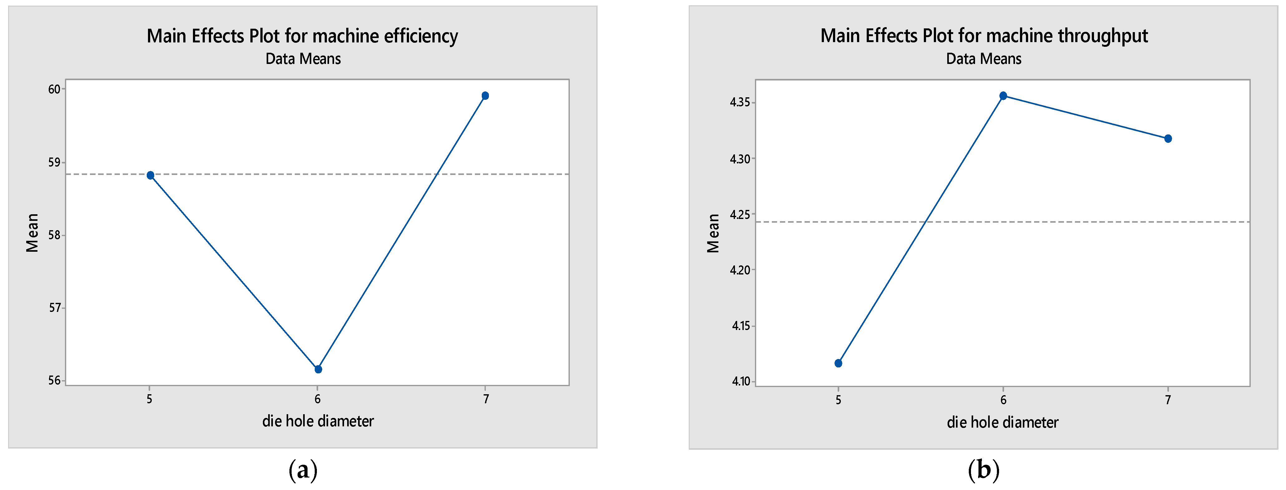
The main effect of die hole diameter on machine efficiency and throughput is shown in Figure 5a,b. Figure 5a shows that machine efficiency decreases with the increase in the die hole diameter to a minimum of 58.82%. It then increases with the increase in the die hole diameter. The maximum and minimum values of 59.92 and 56.16% for machine efficiency were obtained at the 7 and 6 mm die hole diameters, respectively. These values were less, compared to the range of 82.09–91.50% obtained by Sunmonu et al. [43] for fish feed pelletizer and 91.65% obtained by Abdel Wahab et al. [44] for an aquatic feed flat-die pelleting machine. The difference in values may be due to the differences in the properties of the materials used for pelletization. The results of the analysis of variance in Table 4 show that the die hole diameter has no significant effect on machine efficiency. Figure 5b shows that machine throughput increases with the increase in die hole diameter to a maximum and then decrease with the increase in the die hole diameter. The highest value of 4.36 kg/h was obtained at a 6 mm die hole diameter, and the lowest value of 4.12 kg/h was obtained at a 5 mm die hole diameter. These values are comparable to the capacities of 4.32 and 3.21 kg/h obtained by Orisaleye et al. [45] for a feed pelleting machine and lower than the 12.80 kg/h recorded by Birania et al. [46] for a biomass pelleting machine for paddy straw. Similarly, the die hole diameter had no significant effect on machine throughput (Table 4).

3.2. Effect of Die Hole Diameter on Pellet Properties

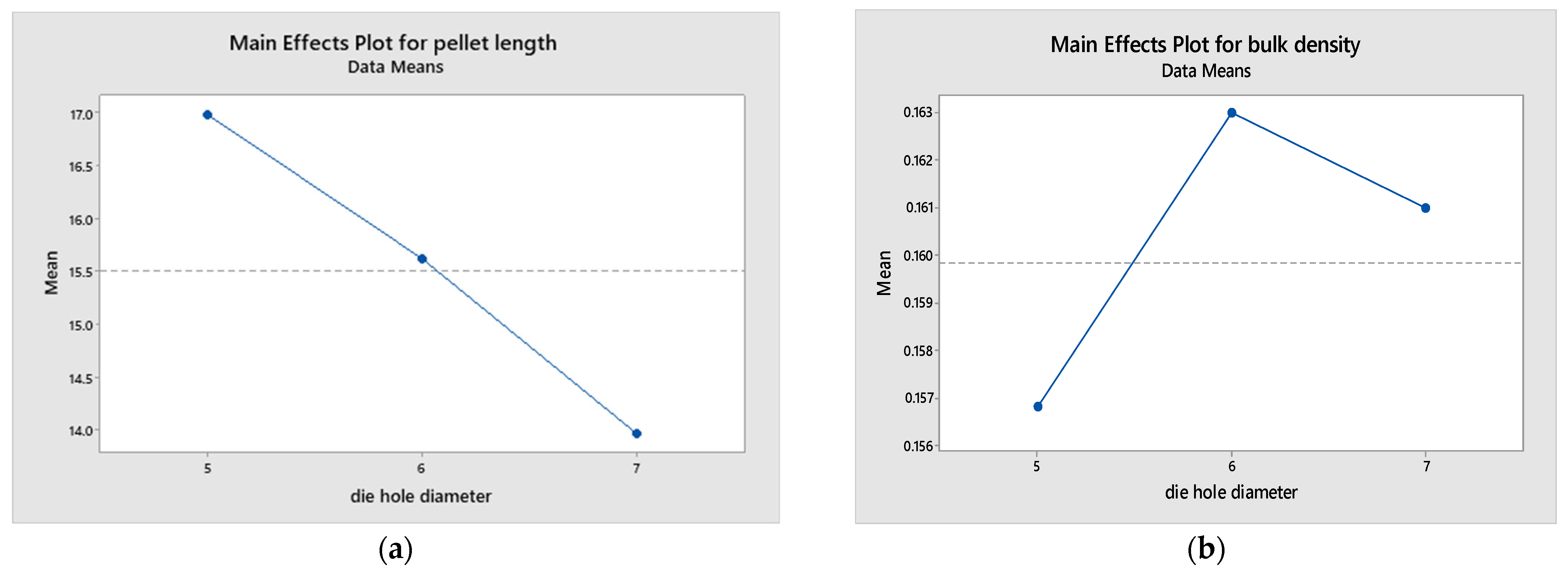
Figure 6a,b show the effect of the die hole diameter on the length and bulk density of pellets. Figure 6a shows that the pellet length decreases with increasing die hole diameter. The maximum and minimum values of 16.98 and 13.97 mm were obtained at 5 and 7 mm die hole diameters, respectively. The values obtained were in the range of 3 < L ≤ 40 mm (where L is length of the pellet, mm), stipulated in the ISO 17829 [47] testing standard for solid biofuels and were close to the range of 13.25–14.00 mm obtained by Liu et al. [48] for a mixture of bamboo and rice straw pellet lengths. Figure 6b shows that bulk density increases with the increase in die hole diameter to a maximum of 0.163 g/cm3 and then decreases with the increase in the die hole diameter. The values obtained were lower compared to the range of 0.6–0.75 g/cm3 stipulated by the ISO 17225-3 [49] standard for solid biofuels, and they were also lower than the range of 0.30–0.9 g/cm3 obtained by Ighodalo et al. [50] for fish feed pellets using a screw-type pelletizer. The lower value of bulk density obtained for the pellets may be due to differences in the physical properties and fiber orientation of corncob. Table 4 shows that die hole diameter has no significant effect on either the length or bulk density of pellets.

3.3. Effect of Binder Quantity on Machine Performance

The main effect of binder quantity on machine efficiency and throughput is depicted by the graph in Figure 7a,b, respectively. Figure 7a shows that machine efficiency decreases with increasing binder quantity. The maximum and minimum values of 68.16 and 51.73% efficiency were obtained at 0.0 and 5.0 wt% binder quantity. The values obtained were comparable to the 63% efficiency obtained by Tashiwa et al. [51] for a motorized fish feed pelletizing machine and lower than the 92.25% obtained by Ikubanni et al. [52] for a screw pelletizer. Figure 7b shows that machine throughput decreases with increasing binder quantity. The maximum and minimum values of 5.39 and 2.95 kg/h throughput were obtained at a 0.0 and 5.0 wt% binder quantity, respectively. The values obtained were comparable to 5 kg/h obtained by Olugboji et al. [53] for a poultry feed pelleting machine. The declining values of machine efficiency and throughput with increasing binder quantity might be attributed to the reduction in frictional forces between the particles and the wall of the compression chamber. Higher binder quantities can create a more lubricated environment, which diminishes the necessary friction required for the effective compression and extrusion of pellets. This lubrication effect reduces the resistance to particle movement, leading to less effective compaction and a subsequent drop in throughput and efficiency.
Additionally, excessive binder may lead to clogging or increased resistance within the die holes, further impeding the smooth flow of material and decreasing overall machine performance. This study’s findings highlight the importance of optimizing the binder quantity to maintain a balance between sufficient lubrication and adequate friction for efficient pelletization. From the analysis of the variance results in Table 4, it is shown that binder quantity has a significant effect on both the efficiency and throughput of the pelletizing machine.

3.4. Effect of Binder Quantity on Pellet Properties

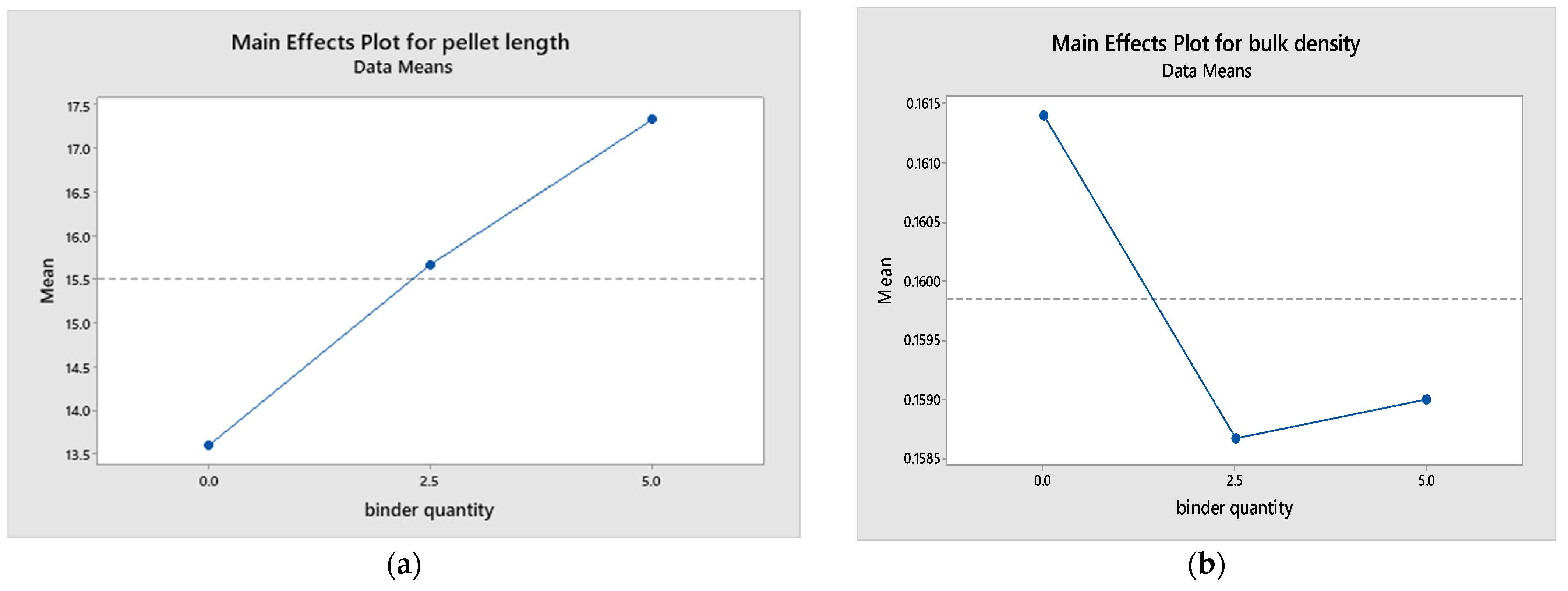
Figure 8a,b show the main effect of binder quantity on the length and bulk density of pellets, respectively. Figure 8a shows that the pellet length increases with increasing binder quantity. The maximum value of 17.32 mm was obtained at 5.0 wt%, and the minimum value of 13.60 was obtained at a 0.0 wt% binder quantity. The values obtained were in the range of 16.63–27.83 mm, as those obtained by Carone et al. [13] for pruning residues of Olea europaea L. pellets, using a single pelletizer unit. Figure 8b shows that bulk density decreases to a minimum with increasing binder quantity and then increases slightly with the increase in binder quantity. The maximum and minimum values of 0.161 and 0.158 g/cm3 were obtained at a 0.0 and 2.5 wt% binder quantity, respectively. The values obtained were lower, compared to the range of 0.30–0.9 g/cm3 obtained by Ighodalo et al. [50] for feed pellets using a screw pelletizer. The lower values of bulk density are due to differences in the physicochemical composition of the feedstocks. It is shown in Table 4 that binder quantity has a significant effect on the pellet length of corncob pellets.

4. Conclusions

This study successfully modified and evaluated an existing hand-operated fish feed pelleting machine to enhance its efficiency and usability for biomass pelletization. The modifications focused on the hopper and power transmission unit, aiming to optimize the machine’s performance for processing corncob biomass. The evaluation considered key factors such as the die hole diameter (5, 6, and 7 mm) and binder quantity (0, 2.5, and 5 wt%).
The results demonstrated that the modified machine achieved an average efficiency of 58.83%, a throughput of 4.24 kg/h, a pellet length of 15.51 mm and a bulk density of 0.160 g/cm3. Notably, the die hole diameter significantly influenced the pellet length, while the binder quantity significantly affected machine efficiency, throughput and pellet length. Specifically, as the binder quantity increased, machine efficiency and throughput decreased, whereas pellet length increased.
These findings indicate that the modified pelleting machine can effectively reduce the bulk density of biomass, thereby lowering handling costs and enhancing ease of use. However, careful consideration must be given to the selection of the die hole diameter and binder quantity to optimize the machine’s performance. The modified machine will aid in the conversion of biomass into energetically usable pellets. Future studies could further refine the machine’s design and explore additional biomass types and binder materials to enhance the versatility and applicability of the pelleting process.

Author Contributions

Conceptualization, S.O.J., F.A.O., F.B.A., M.A.A. and I.A.A.; methodology, M.A.A. and I.A.A.; software, I.A.A.; validation, S.O.J., F.A.O. and F.B.A.; formal analysis, I.A.A.; investigation, I.A.A. and M.A.A.; resources, F.B.A., I.A.A. and M.A.A.; data curation, I.A.A.; writing—original draft preparation, I.A.A. and M.A.A.; writing—review and editing, S.O.J., F.A.O., F.B.A., M.A.A. and I.A.A.; visualization, S.O.J., F.A.O. and F.B.A.; supervision, S.O.J., F.A.O. and F.B.A.; project administration, S.O.J.; funding acquisition, S.O.J., F.A.O., F.B.A., M.A.A. and I.A.A. All authors have read and agreed to the published version of the manuscript.

Funding

This research received no external funding.

Data Availability Statement

The original contributions presented in this study are included in the article; further inquiries can be directed to the corresponding author.

Acknowledgments

The first author (S.O.J.) acknowledges the Equipment Subsidy Grant from the Alexander von Humboldt Foundation, Germany, which aided the execution of this research. All authors wish to appreciate the effort of the technical staff of the Department of Agricultural Engineering, Ladoke Akintola University of Technology, Ogbomoso, Nigeria, for their due diligence and support in providing technical materials and equipment used for this study.

Conflicts of Interest

The authors declare no conflicts of interest. The funders had no role in the design of this study; in the collection, analyses or interpretation of data; in the writing of the manuscript; or in the decision to publish the results.

References

  1. Japhet, J.A.; Tokan, A.; Kyauta, E.E. A Review of Pellet Production from Biomass Residues as Domestic Fuel. Int. J. Environ. Agric. Biotechnol. 2019, 4, 835–842. [Google Scholar]
  2. Mckendry, P. Energy production from biomass (part 1): Overview of biomass. Bioresour. Technol. 2002, 83, 37–64. [Google Scholar] [CrossRef] [PubMed]
  3. Markson, I.E.; Akpan, W.A.; Ufot, E. Determination of Combustion Characteristics of Compressed Pulverized Coal-Rice Husk Briquettes. Int. J. Appl. Sci. Technol. 2013, 3, 61–64. [Google Scholar]
  4. Orisaleye, J.I.; Jekayinfa, S.O.; Pecenka, R.; Onifade, T.B. Effect of densification variables on water resistance of corn cob briquettes. Agron. Res. 2019, 17, 1722–1734. [Google Scholar]
  5. Tumuluru, J.S.; Wright, C.T.; Kenney, K.L.; Hess, J.R. A technical review on biomass processing: Densification, preprocessing, modeling and optimization. In Proceedings of the American Society of Agricultural and Biological Engineers Annual International Meeting 2010, ASABE 2010, Pittsburgh, PA, USA, 20–23 June 2010; American Society of Agricultural and Biological Engineers: St. Joseph, MI, USA, 2010; pp. 4594–4625. [Google Scholar]
  6. Holm, J.K.; Henriksen, U.B.; Hustad, J.E.; Sørensen, L.H. Toward an understanding of controlling parameters in softwood and hardwood pellets production. Energy Fuels 2006, 20, 2686–2694. [Google Scholar] [CrossRef]
  7. Miranda, T.; Arranz, J.I.; Montero, I.; Román, S.; Rojas, C.V.; Nogales, S. Characterization and combustion of olive pomace and forest residue pellets. Fuel Process Technol. 2012, 103, 91–96. [Google Scholar] [CrossRef]
  8. Hu, Q.; Yang, H.; Yao, D.; Zhu, D.; Wang, X.; Shao, J.; Chen, H. The densification of bio-char: Effect of pyrolysis temperature on the qualities of pellets. Bioresour. Technol. 2016, 200, 521–527. [Google Scholar] [CrossRef] [PubMed]
  9. Zainuddin, M.; Rosnah, S.; Noriznan, M.M.; Dahlan, I. Effect of Moisture Content on Physical Properties of Animal Feed Pellets from Pineapple Plant Waste. Agric. Agric. Sci. Procedia 2014, 2, 224–230. [Google Scholar] [CrossRef]
  10. Jackson, J.; Turner, A.; Mark, T.; Montross, M. Densification of biomass using a pilot scale flat ring roller pellet mill. Fuel Process Technol. 2016, 148, 43–49. [Google Scholar] [CrossRef]
  11. Tondare, A.; Nadkar, A.; Zope, V.; Khond, M.P. Design and Fabrication of Biomass Pelleting Machine. J. Adv. Mach. 2018, 3, 6–11. [Google Scholar]
  12. Anenberg, S.C.; Balakrishnan, K.; Jetter, J.; Masera, O.; Mehta, S.; Moss, J.; Ramanathan, V. Cleaner Cooking Solutions to Achieve Health, Climate, and Economic Cobenefits; ACS Publications: Washington, DC, USA, 2013. [Google Scholar]
  13. Carone, M.T.; Pantaleo, A.; Pellerano, A. Influence of process parameters and biomass characteristics on the durability of pellets from the pruning residues of Olea europaea L. Biomass Bioenergy 2011, 35, 402–410. [Google Scholar] [CrossRef]
  14. Nunes, J.; Freitas, H. An indicator to assess the pellet production per forest area. A case-study from Portugal. For. Policy Econ. 2016, 70, 99–105. [Google Scholar] [CrossRef]
  15. Pecenka, R.; Lenz, H.; Jekayinfa, S.O.; Hoffmann, T. Influence of tree species, harvesting method and storage on energy demand and wood chip quality when chipping poplar, willow and black locust. Agriculture 2020, 10, 116. [Google Scholar] [CrossRef]
  16. Orisaleye, J.I.; Ogundare, A.A.; Oloyede, C.T.; Ojolo, S.J.; Jekayinfa, S.O. Effect of preconditioning and die thickness on pelleting of livestock feed. Aust. J. Multi-Discip. Eng. 2024, 20, 13–25. [Google Scholar] [CrossRef]
  17. Jekayinfa, S.O.; Abdulsalam, I.A.; Ola, F.A.; Akande, F.B.; Orisaleye, J.I. Effects of binders and die geometry on quality of densified rice bran using a screw-type laboratory scale pelleting machine. Energy Nexus 2024, 13, 100275. [Google Scholar] [CrossRef]
  18. Orisaleye, J.I.; Jekayinfa, S.O.; Adebayo, A.O.; Ahmed, N.A.; Pecenka, R. Effect of densification variables on density of corn cob briquettes produced using a uniaxial compaction biomass briquetting press. Energy Sources Part A Recovery Util. Environ. Eff. 2018, 40, 3019–3028. [Google Scholar] [CrossRef]
  19. Orisaleye, J.I.; Jekayinfa, S.O.; Dittrich, C.; Obi, O.F.; Pecenka, R. Effects of feeding speed and temperature on properties of briquettes from poplar wood using a hydraulic briquetting press. Resources 2023, 12, 12. [Google Scholar] [CrossRef]
  20. Puig-Arnavat, M.; Shang, L.; Sárossy, Z.; Ahrenfeldt, J.; Henriksen, U.B. From a single pellet press to a bench scale pellet mill—Pelletizing six different biomass feedstocks. Fuel Process Technol. 2016, 142, 27–33. [Google Scholar] [CrossRef]
  21. Wang, T.; Li, Y.; Zhang, J.; Zhao, J.; Liu, Y.; Sun, L.; Liu, B.; Mao, H.; Lin, Y.; Li, W.; et al. Evaluation of the potential of pelletized biomass from different municipal solid wastes for use as solid fuel. Waste Manag. 2018, 74, 260–266. [Google Scholar] [CrossRef]
  22. Stelte, W.; Clemons, C.; Holm, J.K.; Ahrenfeldt, J.; Henriksen, U.B.; Sanadi, A.R. Fuel pellets from wheat straw: The effect of lignin glass transition and surface waxes on pelletizing properties. Bioenergy Res. 2012, 5, 450–458. [Google Scholar] [CrossRef]
  23. Stelte, W.; Clemons, C.; Holm, J.K.; Sanadi, A.R.; Ahrenfeldt, J.; Shang, L.; Henriksen, U.B. Pelletizing properties of torrefied spruce. Biomass Bioenergy 2011, 35, 4690–4698. [Google Scholar] [CrossRef]
  24. Asae/Asabe S2695; Densified Products for Bulk Handling-Definitions and Method. The American Society of Agricultural and Biological Engineers: St. Joseph, MI, USA, 2012; pp. 1–8.
  25. Jekayinfa, S.O.; Adebayo, A.O.; Oniya, O.O.; Olatunji, K.O. Comparative analysis of biogas and methane yields from different sizes of groundnut shell in a batch reactor at mesophilic temperature. J. Energy Res. Rev. 2020, 5, 34–44. [Google Scholar] [CrossRef]
  26. Samuelsson, R.; Thyrel, M.; Sjöström, M.; Lestander, T.A. Effect of biomaterial characteristics on pelletizing properties and biofuel pellet quality. Fuel Process Technol. 2009, 90, 1129–1134. [Google Scholar] [CrossRef]
  27. Crawford, N.C.; Ray, A.E.; Yancey, N.A.; Nagle, N. Evaluating the pelletization of “pure” and blended lignocellulosic biomass feedstocks. Fuel Process Technol. 2015, 140, 46–56. [Google Scholar] [CrossRef]
  28. Fedler, C.B. Mathematical models describing the flow of granular material. Math. Comput. Model. 1988, 11, 510–513. [Google Scholar] [CrossRef]
  29. Huynh, T.; Dao, S. Highly efficient fruit mass and size estimation using only top view images. Multidiscip. Digit. Publ. Inst. Proc. 2019, 42, 57. [Google Scholar]
  30. Singh, S. Mechanical Engineer’s Handbook Ebook; Khanna Publishers: New Delhi, India, 2003. [Google Scholar]
  31. Laloon, K.; Junsiri, C.; Sanchumpu, P.; Ansuree, P. Factors affecting the biomass pellet using industrial eucalyptus bark residue. Biomass Convers. Biorefinery 2022, 14, 10101–10113. [Google Scholar] [CrossRef]
  32. Mani, S.; Tabil, L.G.; Sokhansanj, S. Specific energy requirement for compacting corn stover. Bioresour. Technol. 2006, 97, 1420–1426. [Google Scholar] [CrossRef]
  33. Khurmi, R.S.; Gupta, J.K.K. A Textbook of Machine Design. In Handbook of Machinery Dynamics; S. Chand Publishing: Delhi, India, 2005; 800p. [Google Scholar]
  34. IS:2494-1974; V-Belts—Endless V-Belts for Industrial Purposes, Part 1: General Purpose. Bureau of Indian Standrds: New Delhi, India, 1974.
  35. ASTM E871; Standard Test Method for Moisture Analysis of Particulate Wood Fuels. American Society for Testing and Materials (ASTM): West Conshohocken, PA, USA, 2013.
  36. Frodeson, S.; Henriksson, G.; Berghel, J. Effects of moisture content during densification of biomass pellets, focusing on polysaccharide substances. Biomass Bioenergy 2019, 122, 322–330. [Google Scholar] [CrossRef]
  37. EN 14961-2; Solid Biofuels-Fuel Specifications and Classes—Part 2: Wood Pellets for Non-Industrial Use. European Union: Brussels, Belgium, 2011.
  38. EN 14961-6; Solid Biofuels-Fuel Specifications and Classes—Part 6: Non-Woody Pellets for Non-Industrial Use. British Standards Institution (BSI): London, UK, 2016; p. 18.
  39. Orimaye, O.S.; Ajewole, P.O.; Oni, I.O. Design, Fabrication and Performance Evaluation of Indigenous Fish Feed Pelletizing Machine for Low Income Farmers in Nigeria. J. Eng. Res. Rep. 2019, 4, 1–31. [Google Scholar] [CrossRef]
  40. Prvulovic, S.; Gluvakov, Z.; Tolmac, J.; Tolmac, D.; Matic, M.; Brkic, M. Methods for determination of biomass energy pellet quality. Energy fuels 2014, 28, 2013–2018. [Google Scholar] [CrossRef]
  41. ASTM E873-82; Standard Test Method for Bulk Density of Densified Particulate Biomass Fuels. ASTM International: West Conshohocken, PA, USA, 2014.
  42. Japhet, J.A.; Tokan, A.; Muhammad, M.H. Production and characterization of rice husk pellet. Am. J. Eng. Res. 2015, 4, 112–119. [Google Scholar]
  43. Sunmonu, M.O.; Odewole, M.M.; Falua, K.J. Design of a Varying Die-plate Fish Feed Pelletizer and Performance Evaluation Using a Non-conventional Feed Sources. KMUTNB Int. J. Appl. Sci. Technol. 2018, 11, 263–271. [Google Scholar] [CrossRef]
  44. Abdel Wahab, M.K.; Tawfik, M.A.; El Shal, A.M.; El Hussiny, Y.A. Factors Affecting the Performance of Aquatic Feeds Flat-die Pelleting Machine. Misr J. Agric. Eng. 2011, 28, 129–148. [Google Scholar] [CrossRef]
  45. Orisaleye, J.I.; Ojolo, S.J.; Fashina, A.B. Design and development of livestock feed pelleting machine. J. Eng. Res. 2009, 14, 1–9. [Google Scholar]
  46. Birania, S.; Garg, M.K.; Gupta, R.; Kumar, R.; Kumar, N. Development and Performance Evaluation of Biomass Pellet Machine for On-Farm Sustainable Management and Valorization of Paddy Straw. Environ. Eng. Manag. J. 2021, 20, 2013–2023. [Google Scholar]
  47. ISO 17829; Solid Biofuels—Determination of Length and Diameter of Pellets. International Organization for Standardization: London, UK, 2015.
  48. Liu, Z.; Fei, B.; Jiang, Z.; Cai, Z.; Yu, Y. The properties of pellets from mixing bamboo and rice straw. Renew. Energy 2013, 55, 1–5. [Google Scholar] [CrossRef]
  49. ISO 17225-3; Solid Biofuels-Fuel Specifications and Classes—Part 3: Pellet Quality Requirements. ISO: Geneva, Switzerland, 2015.
  50. Ighodalo, O.; Amiebenomo, S.O.; Esabunor, T. Optimization of multiple performance responses of a fish feed pelletizer machine. J. Adv. Sci. Eng. 2020, 3, 14–23. [Google Scholar] [CrossRef]
  51. Tashiwa, Y.I.; Mojeed, K.A.; Kabri, H.U.; Jilima, A.A. Development of a Motorized Fish Feed Pelletizing Machine. Niger. J. Eng. Sci. Technol. Res. 2019, 5, 96–102. [Google Scholar]
  52. Ikubanni, P.P.; Agboola, O.O.; Adeleke, A.A.; Ogunsemi, B.T.; Ibikunle, R.A. Fabrication and Evaluation of Screw-like Fish Pelletizer. J. Phys. Conf. Ser. 2019, 1378, 022076. [Google Scholar] [CrossRef]
  53. Olugboji, O.; Abolarin, M.; Owolewa, M.; Ajani, K. Design, Construction and Testing of a Poultry Feed Pellet Machine. Int. J. Eng. Trends Technol. 2015, 22, 168–170. [Google Scholar] [CrossRef]
Figure 1. Parts of the existing pelletizing machine; (A) compression chamber, (B) auger of the pelleting unit and (C) pelleting die.
Agriengineering 06 00130 g001
Figure 2. Hopper extension.
Agriengineering 06 00130 g002
Figure 3. Orthographic projection of the pelleting machine.
Agriengineering 06 00130 g003
Figure 4. Exploded view of the pelletizing machine.
Agriengineering 06 00130 g004
Figure 5. Main effect of die hole diameter on machine performance.
Agriengineering 06 00130 g005
Figure 6. Main effect of die hole diameter on pellet properties.
Agriengineering 06 00130 g006
Figure 7. Main effect of binder quantity on machine performance.
Agriengineering 06 00130 g007
Figure 8. Main effect of binder quantity on pellet properties.
Agriengineering 06 00130 g008
Table 1. Bill of engineering measurement and evaluation (BEME).
S/NMaterialDescription and SizesQuantityUnit Cost (Naira)Total Cost (Naira)
1Electric motor4 hp, 1400 rpm140,00040,000
2Angle iron6 × 6 × 2 mm2700014,000
3Bolt and nutM12 × 1.25 mm7100700
4M14 × 2 mm4120480
5Rubber beltType A, 13 × 8 mm; 1255 mm1750750
6Iron plate435 × 280 × 2 mm mild steel160006000
7100 × 100 × 6 mm mild steel5700035,000
8PaintGreen, 2 dm3 525010,500
9Miscellaneous and Workmanship 65,00065,000
Total 161,930
Table 2. Experimental layout for machine performance evaluation.
RunDie Hole Diameter (mm)Binder Quantity (wt%)
12.55
22.56
35.07
40.07
52.57
60.06
75.07
80.05
90.05
105.05
110.07
125.05
135.06
Table 3. Grouping information of machine parameters and pellet properties using the Tukey method.
PropertiesMachine
Efficiency (%)
Machine
Throughput (kg/h)
Pellet
Length (mm)
Bulk
Density (g/cm3)
Die hole diameter
5 mm58.82 a4.12 a16.98 a0.156 a
6 mm56.16 a4.36 a15.62 a0.163 a
7 mm59.92 a4.32 a13.97 a0.161 a
Binder Quantity
0.0 wt%68.16 a5.39 a17.32 a0.161 a
2.5 wt%58.24 ab4.88 a15.67 ab0.159 a
5.0 wt%51.73 b2.95 b13.60 b0.159 a
a,b Means that do not share a letter are significantly different.
Table 4. One-way analysis of variance results for machine performance and pellet properties.
PropertySourceDFSSMSF-Valuep-ValueR2
Machine efficiencyDie hole diameter220.2110.100.080.9261.70
Binder quantity2601.40300.694.600.04250.55
Machine throughputDie hole diameter20.14160.07080.030.9700.69
Binder quantity214.8197.409511.400.00371.71
Pellet lengthDie hole diameter222.7911.3952.450.13632.88
Binder quantity234.8417.4225.060.03050.28
Bulk densityDie hole diameter28.3 × 10−54.1 × 10−52.150.16730.07
Binder quantity22 × 10−51 × 10−50.390.6897.19
Disclaimer/Publisher’s Note: The statements, opinions and data contained in all publications are solely those of the individual author(s) and contributor(s) and not of MDPI and/or the editor(s). MDPI and/or the editor(s) disclaim responsibility for any injury to people or property resulting from any ideas, methods, instructions or products referred to in the content.