This section will cover the electronic and software designs for an HID sensor that is designed to enable auto-calibration algorithms by removing images where technicians have falsely triggered image captures by the VISN system. The objective of this sensor is to identify time stamps when HID events occurred and add those HID time stamps to the database so that later post-processing on the server can omit any images captured during these gin stand maintenance events. In theory, this will allow for the removal of all HID images and thereby enable the use of auto-calibration algorithms.
The initial design was created and tested utilizing off-the-shelf electronic modules, and then once the design was proven, commercial-quality printed circuit board designs were created. The modules were purchased from Sparkfun Electronics, Niwot, CO, USA. Prototype systems were installed into 2 commercial cotton gin plants and tested on 10 gin stands in these commercial facilities for use and testing in the 2022–2023 cotton ginning season in W. Texas, USA.
2.1. Lidar HID Sensing
The hand intrusion and detection (HID) system operates using a Garmin International (Lenexa, KS, USA) Lidar-Lite V3 sensor, which offers a resolution of ±1 cm with an update rate of 650 Hz. In practice, it was found that multiple lidars are required to capture all the HID events. The lidars are positioned 1.5–2.0 m away from the Visual Inspection System Node (VISN), located on the right side of the gin stand. In the first iteration, I2C extenders were utilized to directly connect the lidar units to the ARM computer running the primary machine-vision system. The design provided by this report seeks to improve upon this first design iteration by simplifying access to up to four lidar units from a single reading. This frees up the main ARM machine-vision system from having to poll numerous lidar units for beam break HID events. The design also sought to improve its reliability, as the first generation saw multiple issues with I2C unreliability that were found to be due to the RJ45 cable connectors that were utilized in the I2C extenders from Sparkfun Electronics. When mounted on the gin stand, a high-vibration environment, we found numerous times that the RJ45 connector would work fine until the machine was started and then would stop working. Messing with the connectors could generally eventually get them going; however, even then, they might end up failing later. It was clear that better connectors would benefit the reliability of the system. The design presented herein achieves this by placing a microcontroller in near proximity, less than 15 cm, to all of the lidar units, thereby avoiding the need for an I2C extender so the connection from the lidars to the microcontroller can utilize vibration-robust JST connectors. To address the unreliability of the RJ45 connector connection from the microcontroller to the ARM machine-vision system, the design utilized an ethernet module connected to a m12 ethernet connection that is designed for high-vibration environments. The advantage of this approach is that it will allow any of the ARM systems to read any of the lidar units, thereby providing more fault tolerance to the system. To illustrate the implementation of the HID system on a gin stand,
Figure 3 shows the installation location and how the sensor looks across the cotton gin stand to assess when a technician has stuck his hand, arm, or a stick under the viewing area of the VISN imaging sensor.
The central component of the system is an ARM CPU-based Visual Inspection System Network (VISN), which runs a machine-vision algorithm to automatically detect plastic in the cotton, and it slides underneath the VISN system station. A separate process was run in parallel to connect the HID system to the VISN node via an ethernet Cat-5 cable that is running an I2C network protocol, both electrically and in software. Communication between the lidars and the local VISN system’s Raspberry Pi units is facilitated through the I2C electronic bus using I2C communication protocol. A Cat-5 cable connects the two systems, with each end terminated by a Sparkfun QwiicBus EndPoint (COM-16988; Niwot, CO, USA). The EndPoint incorporates NXP’s PCA9615 IC differential booster (Eindhoven, The Netherlands), enabling extended-range I2C communication and ensuring signal integrity between the two systems. During the deployment process, it was discovered that the hand-made Cat-5 cables were unreliable, leading to the replacement of all hand-made cables with commercially manufactured cables, resulting in improved reliability. However, even with commercially made ethernet cables, there were still reliability issues. These were attributed to the high vibrations of the gin stand exhibits, so it is recommended that future systems avoid RJ45 connects and instead use industrial M12 connectors.
Given the long 1.5 m distance between the VISN node and the HID sensor location, which is well beyond the allowable I2C network distance, the I2C signals were conditioned with an I2C extender to enable running over this extended distance. The I2C extender utilized a PCA9615 I2C extender semiconductor chip from NXP Semiconductors (
www.nxp.com, accessed on 10 October 2023). The PCA9615 extends the I2C bus to allow it to run over cat-5 cables up to 3 m at full speed and further at lower clock speeds. The I2C extender module, Sparkfun product COM-16988, required several adjustments to suit the system application requirements.
Figure 4 shows one of the modified Sparkfun I2C extenders, “EndPoints”, that was situated on each side of the connection, with one unit within the HID enclosure and the other inside the VISN nodes. The attached 6-pin lidar cable, shown in figure, connects the I2C extender to the Garmin Lidar-Lite V3 module, Sparkfun module SEN-14032, which was also configured electrically to communicate over the I2C network.
Figure 5 presents the schematic wiring of the I2C EndPoint connections between the lidar unit and the VISN camera node.
For deployment, communication between the ARM-based VISN and the lidar HID system was established using the software standard I2C communication protocol utilizing open-source I2C libraries written in Python.
The lidar’s datasheet specified the need for a 680 µF capacitor to be placed as close as possible to the lidar to optimize performance when using I2C. This capacitor provides the burst electrical energy needed for each laser pulse from the lidar. This capacitance is provided in the PCB circuit board design through the addition of three 220 μF capacitors for each lidar unit. The lidar also includes a pulse-width modulation (PWM) channel, which can be utilized for communication with the host processor (this research did not utilize this mode; standard I2C communications was used exclusively). For deployment and testing with the HID sensing application, the PWM mode was not utilized. During initial testing, it was determined that I2C would provide some advantages to the VISN system by off-loading some of the processing back onto the lidar unit. However, in the event that any readers want to implement PWM mode, during testing, it was found beneficial to alter the datasheet recommended 1 k resistor that connects to the mode-control pin on the lidar unit. Testing revealed that substituting a 2 k resistor results in an improved waveform with less digital noise, which will make it easier to capture a clean signal transition when digitizing the pulse-width signal from the lidar unit.
2.2. Lidar HID Sensor Design
Due to reliability issues, it was necessary to implement optimization to enhance the lidar performance with an alteration to its operating mode. This was accomplished by changing from default mode to short–fast, so that the lidar was able to take more frequent measurements. This was accomplished by modifying the values stored in the lidar’s internal registers through the use of the Python programming language and Adafruit’s open-source Garmin Lidar-Lite Library, which was modified to enable long-term 24/7 use and enhanced reliability. These changes proved to be beneficial in terms of overall system performance, delivering quicker distance readings and enabling the system to run without faulting out during extended run-time periods. For reader’s convenience, the full test source code is provided in the
supplementary materials. The section on setting the lidar to short–fast mode can be found on line 322 in file lidarlite_test_r8.py. This line calls into a custom “class lidarlite_ext(adafruit_lidarlite.LIDARLite):” found in same file starting on line 124. This code extends the Adafruit Lidarlite interface class to improve long-term reliability. The benefit of switching to short–fast mode is that in the default configuration, many of the shorter-duration HID events, i.e., a quick hand insertion, would fail to be detected. Upon switching to the short–fast mode, the system’s ability to detect short-duration HID events was significantly improved, reducing the required dwell time from >5–10 s to >2–5 s. Note: the range in required dwell times is a feature of the lidar’s firmware, as our system was polling as fast as the lidar allowed.
After deployment of the system, it was concluded that a single lidar unit was inadequate for adequate detection performance of HID events. The team came to this realization after encountering recurrent instances of undetected objects due to the limited coverage area of a single lidar unit. In order to mitigate the issue and ensure improved accuracy, the authors determined that incorporating multiple lidar units would broaden the area of detection and minimize the possibility of missed detections.
2.4. Quad HID Sensor Design
To address the efficacy issues, a four-lidar-sensor HID design was developed with the design specification to provide a robust system architecture that can withstand the harsh industrial environment into which it will be deployed. The design is compact, fitting onto a single printed circuit board, PCB, that was engineered to resist electrical interference and withstand severe vibrations. The circuit board incorporates the following features:
A footprint for an RP2040, Pi-Pico, Broadcom microcontroller (
www.raspberrypi.org; Raspberry Pi Foundation, Cambridge, UK), along with proper voltage spike suppression to ensure stable operation in potentially harsh environments.
Communication back to the machine-vision system can be achieved either via I2C or or the system can utilize an ethernet module that was incorporated in the design, for future research. To provide ethernet connectivity, the PCB design utilizes a W5500-io network module from wiznet.io to provide reliable and efficient communication between the HID and any of the VISN systems. The advantage of the ethernet approach is that it can connect directly to the cloud database server, or the control room computer displaying the data on a web interface which increases its flexibility.
To improve vibration hardening and more reliable communications, the W5500 ethernet module utilizes a M12 ethernet connector.
A lidar interfacing circuit provides the necessary components for communication between the lidar sensors and the microcontroller, allowing for flexibility in the choice of communication method. The user can choose to communicate with the lidar using either pulse width modulation (PWM) or the I2C protocol.
Spare pin headers provide the user with the option to connect external equipment to the system, whether it be analog or digital in nature.
A linear voltage regulator provides a stable and reliable power supply to the system, with proper noise filtering and over-voltage protection to ensure that the system remains operational even in harsh environments. This regulator drops the incoming 5 V power required for the lidar unit down to the 3.3 V required by the Pi-Pico.
A lidar LED indicator circuit provides a visual indication of the lidar’s status, making it easier for the user to determine if the lidar is functioning properly.
A 4-pin M12 connector for ethernet and a 5-pin M12 connector for power and auxiliary output signals were designed to provide a robust and industrial-grade solution for power and external communication. These industrial standard connectors are specifically designed for use in harsh industrial environments and have a well-proven record of providing reliable and durable connections for systems deployed in industrial environments subject to high levels of vibration and electrical noise.
Figure 6 shows the final PCB layout design of the HID board, which features the Wiznet W5500-io network module (Santa Clara, CA, USA). The illustration provides a visual representation of the board layout and its various components, including the Pi Pico’s footprint with proper voltage spike suppression, the lidar interfacing circuit, spare pin headers for connecting external equipment, the linear voltage regulator with noise filtering and over-voltage protection, the lidar LED indicator circuit, and the 4- and 5-pin M12 connectors for power and external ethernet communications. The image is an important representation of the hardware design of the HID board and provides essential information for anyone looking to send the PCB board out to commercial PCB fabrication for seamless replication as well as further understanding of the system. All designs were created in KiCad open-source PCB design software, and the schematic and PCB layout designs for this project are included in the
supplementary materials for this technical note.
2.4.1. Pi Pico PCB Schematic Section Connections
The Raspberry Pi Pico microcontroller is equipped with connections to the power enable, trigger, and monitor pins of each lidar sensor. The analog-to-digital ADC pin header provides convenient and rapid connection to external analog circuits, and even digital ones can be used should the operator choose to add additional functionality. The B130-E3 Schottky diode is integrated to prevent unintended reversed voltage connection to the Vbus pin. Additionally, 2 k ohm pull-up resistors are integrated into the I2C network, allowing the user to utilize the I2C feature with the lidar sensors. The use of pull-up resistors is standard practice for the I2C electrical bus; the reader is referred to any of the I2C bus application notes for more detail, such as the primer provided in [
11]. The Pico board design also features the necessary synchronous-serial SPI connections to communicate with the w5500 network communication module.
Figure 7 details the schematic wiring to the Pi-Pico.
Table 1 lists the design components and vendors utilized in the HID PCB board design for the Pi-Pico section of the PCB board.
2.4.2. W5500 Ethernet Schematic Section Connections
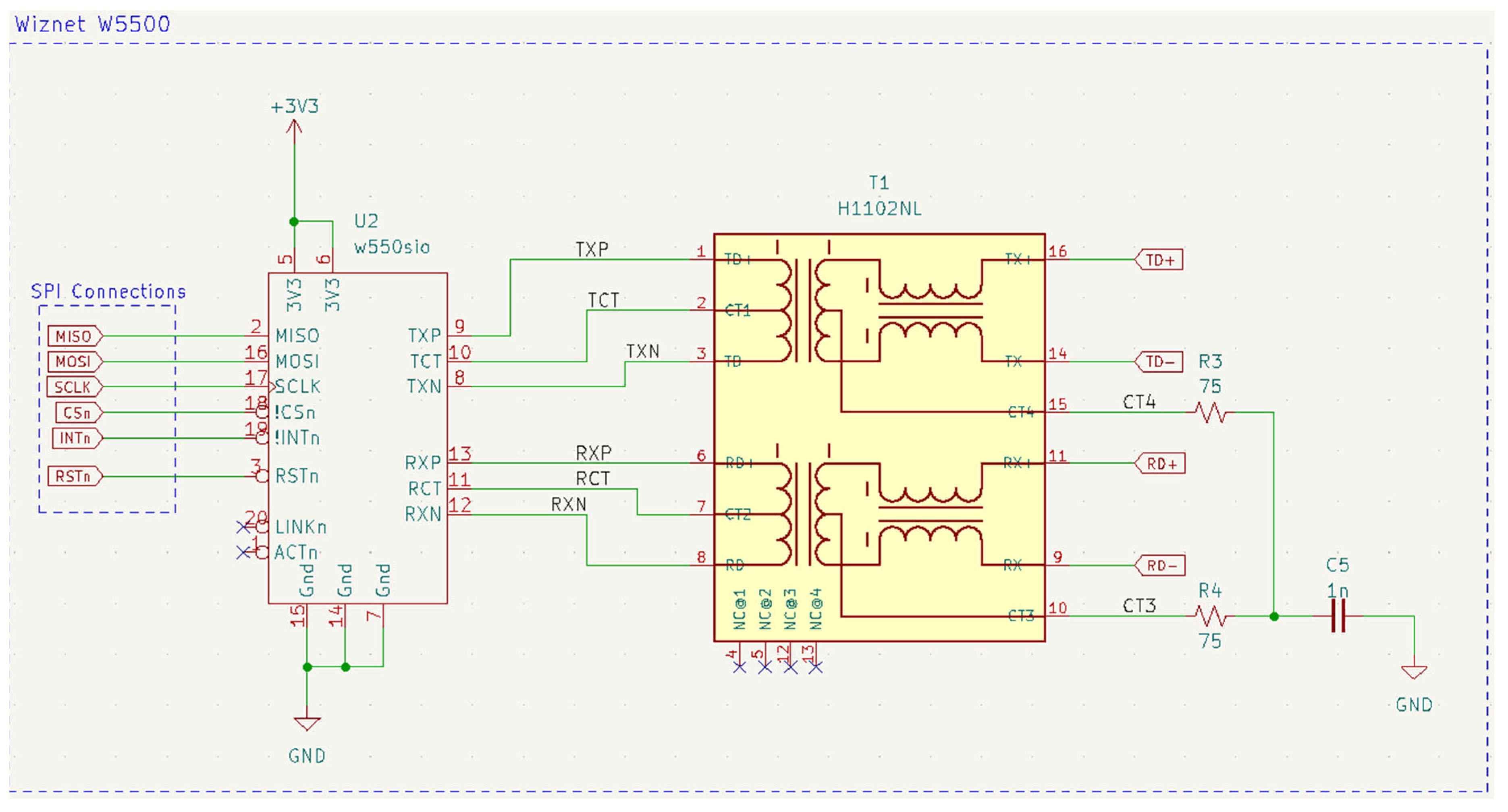
Communication between the Pi-Pico and the Machine-Vision system via I2C, or the Wiznet W5500-io network, is a critical component in the HID system design as it allows for communication between the Pi Pico microcontroller and the cloud server, as well as the control room computer displaying the overall system reports. The research utilized I2C and found it was unreliable in a high vibratory environment, so the next generation version PCB design presented here included the W5500-io as an option. Of note is that the Pi-Pico utilizing W5500-io was not utilized in the research, all testing was performed via I2C interface. The W5500-io however was tested via a parallel development of a Raspberry-Pi daughter board and was found to provide robust solution for use on the high vibratory gin-stands. The W5500-io Raspberry Pi version will be presented in a future publication. Given the dramatic improvement, the W5500-io was also incorporated into the Pi-Pico version detailed herein. The W5500-io module is an integrated Ethernet module that provides ethernet connectivity to embedded systems. It features a hardwired TCP/IP protocol stack and supports multiple communication interfaces, including SPI and 8/16-bit parallel interface. For the HID sensor design, it opted to utilize the SPI interface to communicate between the Pi-Pico and the W5500. As the objective was to avoid RJ45 connectors, a non-standard approach was utilized, bypassing the manufacturer’s suggested design in order to avoid utilizing unreliable RJ45 connectors with integrated magnetics that have connection difficulties in high-vibration environments. Instead, the design utilized a stand-alone ethernet magnetics H1102NL transformer (
www.pulseelectronics.com, accessed on 10 October 2023; Pulse Electronics, San Diego, CA, USA), which provides signal conditioning output to the 4-pin M12 ethernet connector. Details on design of the H1102NL pulse transformer and the W5500-io module are shown in
Figure 8. Of note is that the ethernet lines carry high-frequency signals, so each PCB trace line was impedance-matched to 50 ohms, and care was taken to remove all the copper flood fill from the PCB region where these lines were located. Further, care was taken to provide good separation between each trace and proper usage of bypass capacitors. For more detail on high-speed layout, consult any number of textbooks and online application notes on the subject [
12,
13,
14,
15,
16,
17,
18,
19,
20]. To further aid in high-frequency performance and layout, all components utilized 0805-sized surface-mount ceramic chip capacitors and surface-mount chip resistors. As target was a high-vibratory environment, in several cases, use of multiple smaller chip capacitors in parallel was utilized to reduce the mass and enhance the adhesion to the circuit board for higher-value capacitors.
Table 2 lists the design components and vendors utilized in the HID PCB board design for the w5500 section of the PCB board.
2.4.3. Lidar Circuit
Each of the four Garmin (Olathe, KS, USA) Lidar-Lite V3 lidar units is connected to the printed circuit board through the use of surface mount JST 6-pin SM06B-GHS-TB connectors. The JST connectors provide an industry standard connector that provides a comprehensive and robust connection for power and communication between the lidar and the PCB as well streamlines manufacturing, as JST cables are readily available and the JST connectors can be placed by commercial pick-and-place machines, thereby avoiding the need for high-labor and cost through-hole connections. In combination, the use of JST connectors significantly eliminates many steps in the manufacturing process of the HID units. To ensure reliable performance of the lidar units, three 220 μF surface mount capacitors are used to filter and stabilize the power input to the lidar unit. These capacitors help to smooth out any voltage fluctuations due to large power dump that occurs when the laser fires and prevent any adverse effects on the I2C communication between the lidar and the Pi Pico microcontroller. If pulse width modulation (PWM) is the desired method of communication with the Pi Pico, it is recommended to include a 2 k ohm resistor in the circuit to smooth out any noise and split the mode control pin into a trigger and monitor pin, as shown in
Figure 9 (the PWM mode, which requires the 2 k resistor, was not utilized in the research reported on herein. The research utilized I2C for all communications between the microcontroller and each of the lidar units).
Table 3 lists the design components and vendors utilized in the HID PCB board design for the lidar section of the PCB board.
2.4.4. M12 Connectors
The HID system utilizes two industrial-grade M12 connectors, one male and one female, to facilitate the power supply and communication between the system and the control room computer. The 5-pin M12 female connector is designed to bring the necessary 5 V power to the system and provides optional I2C communication and an additional analog line for extended functionality. The 4-pin M12 male connector, on the other hand, contains the outputs from the H1102NL transformer, transmitting signals back to the control room computer, allowing for communication between the two systems. These robust M12 connectors ensure a secure and reliable connection between the components, offering optimal performance and seamless integration of the HID system in the control room infrastructure. The circuit connections to the M12 connectors are detailed in
Figure 10.
Table 4 lists the design components and vendors utilized in the HID PCB board design for the M12 connectors section of the PCB board.
2.4.5. Input Voltage Regulation
The input voltage design for the system is 5 V, as that is what is required by the four Garmin Lidar-Lite V3 modules. To obtain power for the RP2040 microcontroller, the design of the circuit board incorporates a linear voltage regulator, MIC5205-3.3YM5,
www.microchip.com, which steps down the incoming 5 V power to a stable 3.3 V output. This 3.3 V output is also used to power the Wiznet W5500-io module and serves as the source voltage for the I2C pull-up resistors, which enable the board to communicate via I2C to other 3.3 V devices such as an ARM-based micro-computer. The voltage regulation circuit has been optimized to maintain stability with the inclusion of three 10 μF decoupling capacitors and a 0.1 μF decoupling capacitor, along with a transient voltage suppressor diode (TVS8501V5MUT5G) that safeguards against voltage spikes that are common in industrial environments, such as the target deployment destination. Additionally, a 1 nF bypass capacitor that is connected to the bypass pin enhances the low-noise performance of the circuit. To maintain operational stability and prevent oscillation, two 10 μF output capacitors are connected in series. The use of two 10 μF capacitors allows for use of smaller surface mount chips, which are less expensive as doubling up the components, rather than introducing a new part, lowers the cost by allowing for volume discounts as well as reduces part count of the design, thereby lowering inventory requirements. The schematic details are provided in
Figure 11.
Table 5 lists the design components and vendors utilized in the HID PCB board design for the linear voltage-regulation section of the PCB board.
2.4.6. Light-Emitting Diode, LED, Indictor Circuits
The circuit design of the system features indicator LEDs for each of the lidar units. The LEDs serve as a quick diagnostic tool, providing the operator with real-time insight into the status of each of the lidar units. Each LED is connected to the monitor pin on its corresponding lidar module, thereby causing it to switch on and off in response to the transmission of data between each lidar and the RP2040 microcontroller. To control the flow of current to the LED, a MOSFET transistor is utilized, ensuring a reliable and consistent source of illumination. With this design, the operator is able to quickly and easily determine the operational status of the lidar units, improving system performance and maintenance. In implementing the housing design, it is suggested to utilize light pipes to bring out each of the indicator LEDs to provide high visibility of the state of operational status for each lidar unit and the RP2040.
Table 6 lists the design components and vendors utilized in the HID PCB board design for the LED indicators section of the PCB board.
Table 6.
List of components and their functions in the schematic, as depicted in
Figure 12.
Table 6.
List of components and their functions in the schematic, as depicted in
Figure 12.
| Qty | Value | Parts | Part # | Vendor | Description |
|---|
| 4 | | LED 1-4 | HSMY-C170 | Broadcom Limited (San Jose, CA, USA) | Yellow LED |
| 12 | 75 Ω | R 9-20 | RMCF0805JT75R0 | Stackpole Electronics | Resistor (0805 SMD) |
| 4 | | Q 1-4 | BSS127IXTSA1 | Infineon Technologies (Neubiberg, Germany) | MOSFET |
2.5. HID Software Design
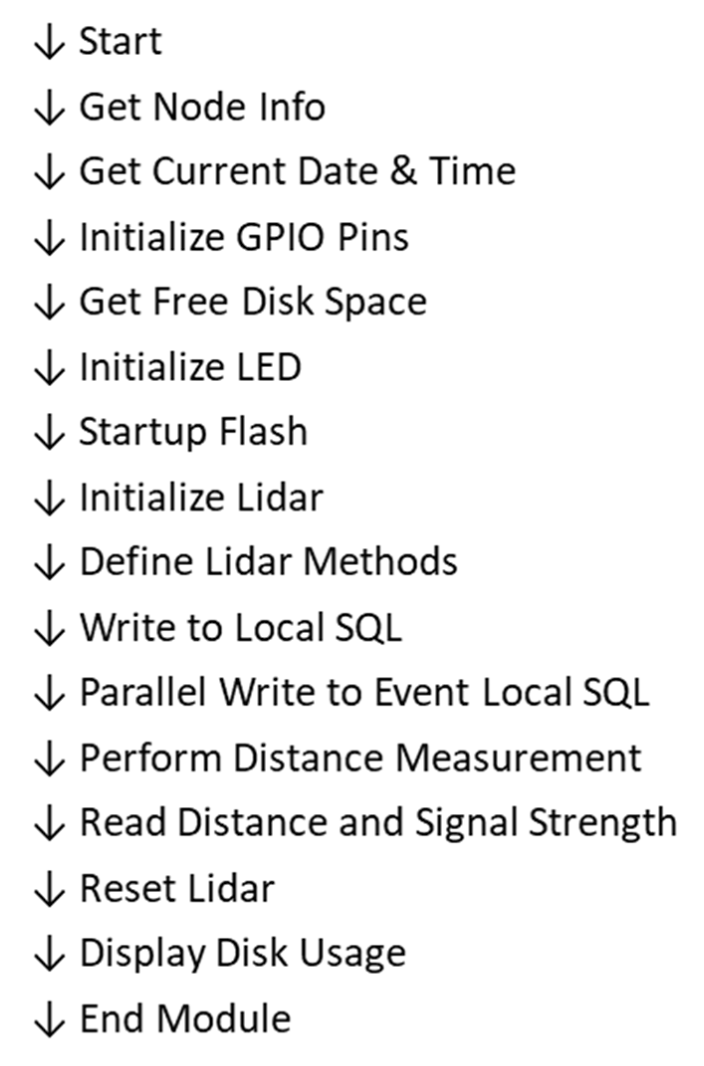
The data-acquisition process from the lidar devices was developed in Python and utilized Adafruit’s CircuitPython LIDARLite I2C library module code. In initial testing, the I2C library code was found to be faulty after extended runtimes due to not handling all situations correctly. To provide a solution that could run continuously for days, it was necessary to extract the I2C library code, modify it, and embed the key structures directly in our lidar code, hereafter known as “modified I2C” library code. To establish I2C communication with the lidar devices, the modified I2C library module is leveraged, offering a streamlined and effective approach to interface with the lidars via I2C network protocol. The libraries provide abstracted functions that operate at a higher level, facilitating data transmission and reception over the I2C bus. These functions encompass operations such as specifying the target device address, conducting read and write operations, as well as handling errors and allowing access to the devices’ internal registers. To visually illustrate the step-by-step process of the lidar software workflow,
Figure 13 presents a comprehensive flowchart showcasing the I2C communication and data flow between the host device and sensor. This code is specifically designed for utilization on the VISN system’s ARM micro-computer.
The flowchart in
Figure 13 showcases the software protocol utilized to obtain the lidar distance data and highlights the employment of I2C communication for acquiring precise distance and return-signal-strength, RSSI, measurements from the lidar. The feed-forward process steps encompass the setup of the lidar, data retrieval via I2C, and subsequent storage of the acquired data into a local SQL database.
The writing of the data into SQL databases is achieved through a set of purpose-built helper functions. These functions are designed to simplify the structure of the code into high-level and lower-level tasks to improve the readability and maintenance of the code utilized in the reading, writing, and updating of the SQL tables. The use of abstract data types provides enhanced convenience and efficiency in the overall process.
Figure 14 provides a list of the available functions located inside the module.
The utility functions, shown in
Figure 14, are designed to provide efficient and convenient interactions with the database, encompassing tasks such as reading, writing, and updating the data in the SQL databases. There are two sets of SQL utility functions: one set is targeted at reading and writing to the local SQL database, and the other set provides equivalent functions targeted at reading and writing to an SQL database on the cloud server that acts as the master controller and data store. The cloud-SQL utility functions are utilized by a background Python process that copies the data from the local SQL database up to the cloud SQL database for use by the auto-calibration algorithms running on the cloud server.
The latest software module developed facilitates interaction with a Wiznet W5500-io network module connected to an RP2040 microcontroller (Pi Pico), which is the master controller that provides data collection for each of the four lidar units. The communication between the Pico and the Wiznet W5500-io module is established using SPI (Serial Peripheral Interface). SPI is an industry-standard synchronous serial electrical bus and communication protocol that allows for high-speed data transfer between devices over short distances. Pico and W5500-io are configured to communicate with each other using SPI with up to a 10 MHz clock, thereby enabling efficient and reliable data exchange between the two devices. The custom Pico PCB board was designed to simplify testing and setup of the W5500 module.
Figure 15 presents a visual representation of the startup sequence of the module, providing an overview of its configuration. The W5500 was configured to utilize DHCP (Dynamic Host Configuration Protocol) to establish its IP address. Given the non-deterministic nature of DHCP, the Pico board was designed with the intent to only upload data to the cloud server data via a simple web-based Javascript object notation (JSON) protocol to an application programming interface (API) running on the cloud server’s website.
This concludes the overview of key highlights of the code. For complete details, the reader is referred to the actual code, which is well documented and is included as a
supplementary material to this technical note.


 ,
, 
