Article

Development of a Novel IoT-Based Hierarchical Control System for Enhancing Inertia in DC Microgrids

1
Electrical Power and Machines Engineering Department, Faculty of Engineering, Tanta University, Tanta 31511, Egypt
2
State Key Laboratory of Advanced Electromagnetic Engineering and Technology, Huazhong University of Science and Technology, Wuhan 430074, China
*
Author to whom correspondence should be addressed.
Smart Cities 2025, 8(5), 166; https://doi.org/10.3390/smartcities8050166
Submission received: 15 June 2025 / Revised: 25 August 2025 / Accepted: 17 September 2025 / Published: 8 October 2025
(This article belongs to the Section Smart Grids)

Abstract

Highlights

What are the main findings?
  • A hierarchical control strategy combining decentralized SG-emulating converters and centralized IoT-based coordination is proposed.
  • The method significantly improves inertial response and voltage stability in DC multi-microgrid (DCMMG).
What is the implication of the main finding?
  • The proposed approach enables effective real-time cooperation between distributed energy storage units, enhancing system reliability.
  • It facilitates greater integration of renewable energy sources into DC microgrids by addressing the low.

Abstract

One of the main challenges faced by DC microgrid (DCMG) is their low inertia, which leads to rapid and significant voltage fluctuations during load or generation changes. These fluctuations can negatively impact sensitive loads and protection devices. Previous studies have addressed this by enabling battery converters to mimic the behavior of synchronous generators (SGs), but this approach becomes ineffective when the converters or batteries reach their current or energy limits, leading to a loss of inertia and potential system instability. In interconnected multi-microgrid (MMG) systems, the presence of multiple batteries offers the potential to enhance system inertia, provided there is a coordinated control strategy. This research introduces a hierarchical control method that combines decentralized and centralized approaches. Decentralized control allows individual converters to emulate SG behavior, while the centralized control uses Internet of Things (IoT) technology to enable real-time coordination among all Energy Storage Units (ESUs). This coordination improves inertia across the DCMMG system, enhances energy management, and strengthens overall system stability. IoT integration ensures real-time data exchange, monitoring, and collaborative decision-making. The proposed scheme is validated through MATLAB simulations, with results confirming its effectiveness in improving inertial response and supporting the integration of renewable energy sources within DCMMGs.

1. Introduction

The increasing global demand for energy, combined with the depleting conventional resources and their adverse environmental impacts, has intensified the global energy crisis. As a result, renewable energy sources (RES), such as solar and wind power, have emerged as promising alternatives. Distributed generation systems that utilize these renewable sources are gaining widespread adoption due to their flexibility, cost-effectiveness, and reduced environmental footprint compared to conventional centralized power generation systems [1]. The microgrid paradigm has become a viable solution for integrating renewable energy sources and energy storage systems (ESS) to meet the diverse needs of modern energy systems [2,3]. While both AC and DC microgrids are utilized, DC microgrids have emerged as a particularly efficient and reliable approach for integrating various renewable energy sources and loads [4,5]. Their inherent simplicity eliminates the need for complex AC power conversion processes, enhancing system reliability and reducing costs. By directly interfacing DC sources such as solar panels and electric vehicles, DC microgrids enable streamlined energy distribution, ensuring higher efficiency and improved performance. This efficiency makes DC microgrids a promising platform for future energy systems.
To fully reveal the potential of DC microgrids across various applications, robust control strategies are essential. The primary control objectives for DC microgrids include maintaining stable DC bus voltage, ensuring suitable power sharing among connected Distributed Energy Resources (DERs), enhancing inertia, and optimizing the operation of energy storage systems to enhance system reliability and efficiency. To realize these control objectives, several control strategies have been proposed, including centralized, decentralized, distributed, and hierarchical control approaches [5,6]. Each of these approaches offers distinct advantages and limitations. Centralized control provides high coordination but is vulnerable to single points of failure, which can compromise system reliability. Distributed control improves scalability and reliability by spreading decision-making across multiple nodes, but it requires a complex communication infrastructure. Decentralized control operates solely on local information, eliminating single points of failure and reducing communication requirements. However, its functionality is limited due to the lack of global coordination. Hierarchical control combines decentralized control with centralized or distributed approaches. In this structure, the primary control function is decentralized, focusing on local stability and immediate response, while the secondary function is centralized or distributed, enabling higher-level coordination and optimization. The choice of the appropriate control strategy depends on the specific system architecture and the desired functionality, balancing trade-offs between reliability, scalability, and complexity.
One of the most widely used decentralized control methods in DC microgrids is droop control. This method helps maintain the bus voltage within the permissible limits by adjusting the output of Distributed Generators (DGs) according to the load demand. Droop control enables efficient power allocation between local DGs without requiring communication between them. Additionally, it can balance batteries performance by making the droop factor a function of the State of Charge (SOC) of each battery unit [7]. However, despite its advantages, droop control has a notable impact on the dynamics of the DC bus voltage. Since the droop control equation is inherently static and lacks internal states, any fluctuation in the load directly affects the terminal voltage. This limitation results in rapid voltage oscillations during sudden load changes. To address these challenges, incorporating virtual inertia control into DC microgrids has emerged as a promising approach to improving voltage quality [7,8]. Recent studies on simulated inertia control focus primarily on enhancing the operation of power converters by providing active power support to the main grid or AC MGs [9]. Among the various approaches, Virtual Synchronous Machines (VSMs) are widely regarded as effective tools for implementing virtual inertia control in converter operation [10]. The synchronverter concept, introduced in earlier research, emulates the performance of synchronous machines (SMs) by replicating their electromagnetic and mechanical equations. Due to its superior control capabilities, VSM control has been successfully applied in numerous systems, including Voltage Source Converter (VSC) stations and energy storage systems [11].
Research on simulated inertia control in DC microgrids (DCMGs) remains limited, with existing methods categorized into three main approaches: modifying the droop coefficient, simulated DC machine control, and Analogized Virtual Synchronous Machines (AVSM) [9]. Regarding modifying the droop coefficient, it links the rate of change in the DC bus voltage to the droop coefficient. For example, the authors in [12] developed a droop control swing characteristic curve that responds to voltage fluctuations, allowing additional current to stabilize DC voltage during transients. However, this method introduces a voltage drop in the control strategy, which can increase frequency disturbances. Another enhancement involves adding a high-pass filter in the inertia control loop to reduce the effect of high-frequency disturbances [13]. While this helps suppress voltage fluctuations, it may result in a slower system response. Regarding the simulated DC machine control, it represents a further development of the inertia concept, where it builds on the operational characteristics of DC machines to develop an inertia concept [14]. However, the theoretical design of this approach is highly complex, making practical implementation challenging. Another approach is to apply AVSM control strategy for enhancing virtual inertia in a DCMG by transferring it to bidirectional grid-connected converters [15]. However, this method is limited to Buck-Boost Converters, restricting its ability to provide inertia support in islanded mode and failing to improve system damping. In [16], the authors introduced simulated inertia control based on AVSM for battery converters in islanded DCMGs. While effective in some scenarios, this approach did not account for the necessity of a variable droop factor to balance battery performance.
None of these methods sufficiently addressed scenarios where converters reach their maximum current limits or batteries enter full charge or discharge states. In such cases, the control system may fail to maintain optimal performance due to constraints imposed by converter capacity or battery states of charge. This limitation underscores the need for innovative solutions. To address these challenges, this paper proposes the concept of interconnecting microgrids as a potential solution to enhance system stability and reliability. By leveraging the collective capacity of interconnected microgrids, this approach aims to overcome the limitations of individual systems and ensure more robust and efficient operation.
Recently, DCMGs have been interconnected to form clusters known as Integrated Microgrid (IMG) networks. Compared to individual MGs, an IMG network offers greater control flexibility, allowing it to better meet the demands of larger grid systems. The advantages of IMG networks include increased grid reliability, optimized utilization of DERs, improved power quality for residential users, better power supplied to remote areas, and more efficient management of load demand [17,18]. These benefits are realized through effective coordination and control between interconnected microgrids. Research efforts have increasingly focused on implementing coordination control for IMG networks. In [19,20,21,22,23], various control methods have been proposed, primarily aimed at ensuring proper power sharing among converters and maintaining the buses voltage within acceptable limits. However, existing studies have not explored how interconnecting microgrids could be leveraged to enhance the inertia system. Additionally, many of the proposed methods rely heavily on distributed control, which is more complex and can lead to inefficiencies. Such challenges may result in instability, reduced reliability, and difficulty in managing large-scale systems.
Based on the aforementioned challenges and opportunities, this paper proposes a hierarchical control strategy utilizing IoT technologies to ensure system voltage stability and enable effective power sharing of ESUs. The proposed control strategy aims to stabilize the system voltage, facilitate effective power sharing among ESUs, and maintain a balanced equilibrium between loads and generation. Furthermore, the strategy integrates a mechanism that supports the system inertia, which is a crucial factor in minimizing voltage fluctuations and maintaining overall grid stability. This innovative approach ensures efficient energy distribution while addressing the limitations of existing methods. Therefore, the key contributions of this work are as follows:
  • Real-time monitoring of multiple DC microgrids (MGs) through IoT technology.
  • Development of a hierarchical control structure that combines decentralized and centralized control methods. The decentralized control managing local battery operations to improve inertia through individual responses to system dynamics, while centralized control, based on IoT coordinates and optimizes battery collaboration to ensure overall system balance and stability.
  • Detailed explanation of secondary control strategies employed to facilitate collaborative operation between batteries, accompanied by an analysis of the effectiveness of these strategies in achieving system balance.
  • Verification of the control method’s effectiveness through the development of a DC microgrid model, followed by an analysis of the system’s performance under various operating conditions. The results demonstrated the proposed control method’s effectiveness in enhancing overall system performance.
The rest of this paper is organized as follows: Section 2 provides a description of the structure of DCMGs. Section 3 offers an overview of the control methods employed in microgrids. Section 4 presents a detailed explanation of the VIC method implemented in this study. Section 5 thoroughly examines the secondary control approach used to facilitate collaboration between the ESUs. Section 6 presents the system simulation results, while Section 7 concludes the paper with final remarks and suggestions for future work.

2. System Description

The system considered in this paper is illustrated in Figure 1. It consists of a network of multiple DC MGs that are monitored and controlled through IoT technology. Each microgrid integrates various energy sources, such as solar panels and batteries, to supply power to the loads. These microgrids are equipped with smart meters, sensors, and controllers that enable real-time monitoring and management of the system. The IoT platform acts as the central communication hub, facilitating remote control and optimization of energy generation, storage, and consumption across microgrids. Through the IoT network, operators can monitor the performance of each MG, analyze energy usage patterns, and adjust system settings to improve efficiency and reliability. According to the proposed IoT-based hierarchical control strategy, the system is organized into three layers as described below.
  • The First Layer
This is the base layer, which includes all the physical components of the system. It consists of four interconnected DC MGs linked together through tie lines. Each DC MG integrates various DERs, including renewable energy sources such as photovoltaic (PV) panels, energy storage systems, and different types of loads. A typical PV system includes a PV array and a power electronic converter, like a boost converter. The performance of the PV system is optimized through the implementation of a Maximum Power Point Tracking (MPPT) control algorithm. This algorithm continuously monitors solar irradiance and cell temperature to regulate the operating point that maximizes the power output from the PV array. By ensuring that the PV system operates at its maximum power point, it achieves optimal energy production.
Energy Storage Units (ESUs) play a crucial role in microgrids, especially for integrating RESs, as they help mitigate power fluctuations. In some cases, ESUs can serve as the sole power source for loads. The voltage level of the ESS has a significant impact on the bus voltage of the microgrid, making it a critical factor for maintaining system stability and performance. Additionally, the investment in ESS infrastructure is substantial, emphasizing the importance of their efficient operation.
To optimize performance and enhance longevity, IoT-enabled monitoring systems can track real-time data on the state of charge (SoC) and current of each battery unit. By analyzing these data, advanced control algorithms can be implemented to maximize battery lifespan, minimize energy storage costs, and improve overall system efficiency. In larger microgrids, geographic location can also be considered when dispatching power to nearby loads, thereby reducing transmission losses and enhancing system reliability. The operation and management of these microgrids are coordinated through a hierarchical control strategy based on IoT. IoT technologies enable real-time monitoring and control of microgrid components, providing a seamless communication network between all microgrids. Sensors and smart meters are distributed throughout the system to gather data on key parameters, including voltage, current, state of charge (SoC) of batteries, and energy consumption patterns. This data is transmitted to the IoT cloud, where it is processed and analyzed to ensure efficient operation and optimized system performance.
  • The second layer
This layer is a communication layer, which serves as the backbone of IoT-enabled microgrids by facilitating seamless data exchange between physical devices and the IoT cloud. It involves collecting data from various sensors and meters, transmitting it to the IoT cloud for analysis, and executing commands sent from the IoT cloud to control devices within the microgrid. Key components of this layer include devices such as smart meters and sensors, communication protocols like Modbus, MQTT, HTTP, and CoAP, network infrastructure (both wired: Ethernet, powerline communication and wireless: Wi-Fi, Bluetooth, Zigbee, LoRa WAN) and gateways [24,25]. Designing this layer comes with several challenges, including ensuring interoperability, security, reliability, and scalability, and minimizing latency. The IEEE 802.11i standard addresses these concerns by incorporating Wi-Fi Protected Access 2 (WPA2) encryption and the Advanced Encryption Standard (AES) [26]. A significant advantage of Wi-Fi is its widespread compatibility with a wide range of electronic devices. Communication delay is an important consideration in IoT-based control systems, and its impact varies depending on the specific application layer. Time-critical functions, such as primary control and real-time voltage regulation, typically require ultra-low latency—often within 2 ms—to ensure fast and stable system response. In contrast, higher-level functions like SoC balancing, energy management, and data logging are more tolerant to delay, with acceptable latencies ranging from several hundred milliseconds to a few minutes. The selection of communication technologies should therefore align with the latency and reliability requirements of each control layer. A detailed overview of available communication protocols, their coverage areas, and data rates is provided in [18], offering guidance for practical implementation. This layered approach allows the proposed control framework to maintain performance and scalability while accommodating the inherent variability in IoT communication networks.
By overcoming these challenges, IoT-enabled microgrids can achieve real-time monitoring, predictive maintenance, optimized energy management, remote control, and data-driven decision-making [24].
  • The third layer
This layer serves as the “brain” of any intelligent system in the IoT framework. It is responsible for processing information and making decisions based on the available data. After data is collected and transmitted through the communication layer, it reaches this layer where it is analyzed and interpreted. This layer employs various algorithms and machine learning techniques to extract meaningful insights from the raw data. Based on these insights, the system generates control signals or commands, which are then sent back to the devices within the network. In this paper, the IoT cloud receives data from each battery in the network, calculates the reference value for all batteries, and then sends the reference value to each battery to achieve an SOC balance.

3. Proposed Hierarchical Control Strategy for DC Microgrids Based on IOT

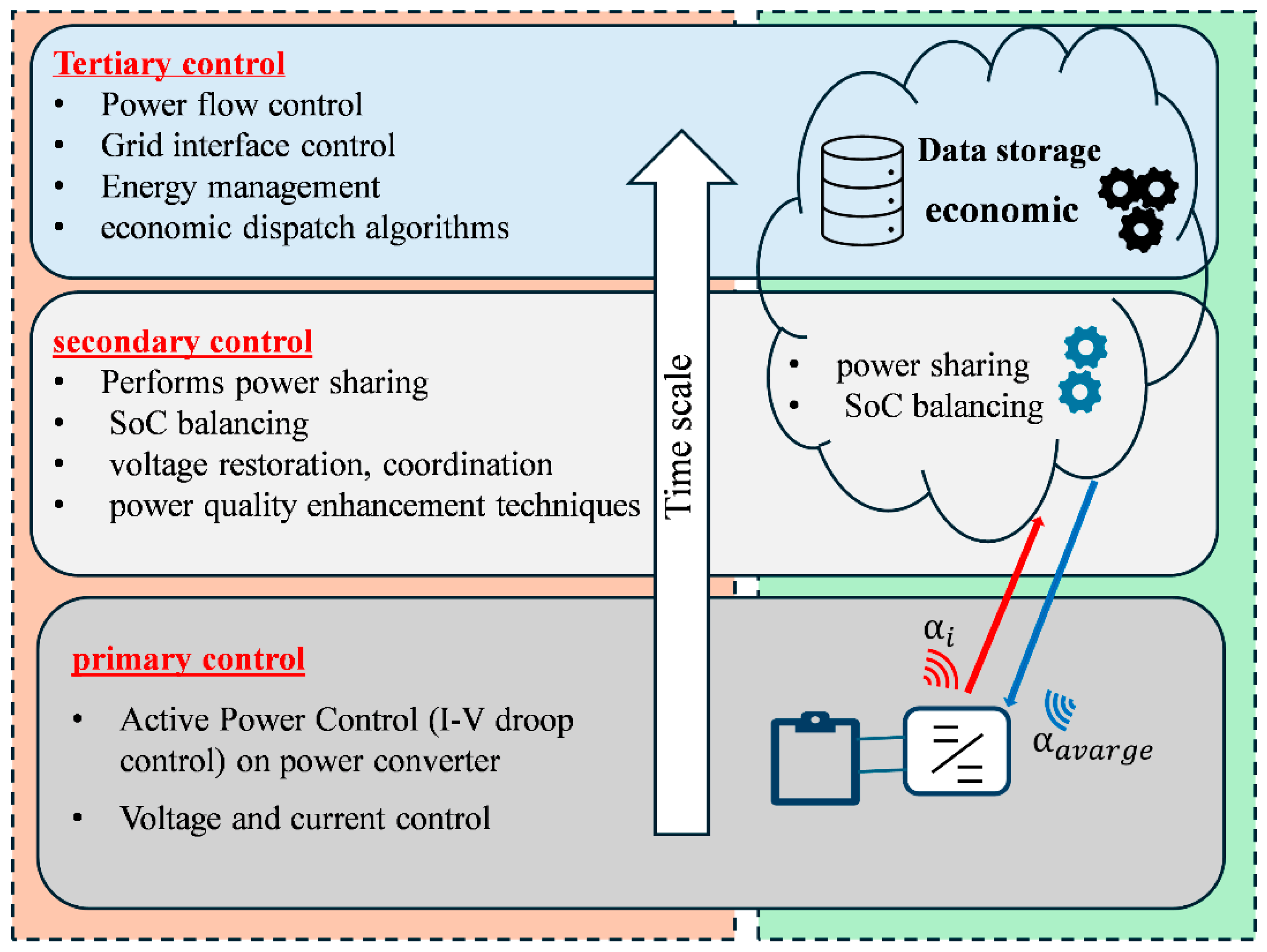
The hierarchical control strategy consists of three control levels, as shown in Figure 2: the primary control level, the secondary control level, and the tertiary control level.

3.1. Primary Control

The primary control layer in DC microgrid is essential for maintaining system stability and ensuring power sharing among distributed energy sources. By employing decentralized control strategies, such as droop control, the primary control level allows individual converters to autonomously adjust their output voltage based on local measurements [27]. While droop control is effective in achieving power sharing, the lack of inherent inertia in DC microgrids can limit the dynamic performance of the system and its resilience to disturbances [10]. To address this limitation, virtual inertia control strategies are implemented to emulate the stabilizing effects of synchronous generators based on droop control. This enhances the ability of DC microgrids to handle disturbances, making them suitable for a wide range of applications, including residential, commercial, and industrial settings. Although primary control can effectively manage the operation of a single microgrid, it lacks the coordination mechanisms necessary to regulate an interconnected system. When multiple microgrids are connected, voltage deviations can occur, and power may not be shared equitably among the microgrids. Therefore, secondary control is needed to coordinate the operation of multiple microgrids, ensuring that the overall system operates within acceptable limits.

3.2. Secondary Control

This control layer is responsible for power sharing, such as the proposed SoC balancing technique. It coordinates the primary control of the ESUs and requires continuous communication with each ESU converter. This communication is facilitated through long-range IoT networks, enabling constant interaction and coordination across the system.

3.3. Tertiary Control

This layer incorporates advanced energy management strategies, including analytics, economic optimization, and dispatch algorithms. It focuses on long-term planning and control to achieve broader energy management goals. While the proposed IoT architecture enables data collection and analysis for tertiary control, a detailed exploration of specific implementations is beyond the scope of this paper.

3.4. Proposed Control Strategy for Multi-DC Microgrids

Interconnecting multiple microgrids offers several advantages, including enhanced reliability and resilience. By forming a larger network, microgrids can support each other during periods of high demand or outages. Additionally, interconnected microgrids can optimize the utilization of distributed energy resources (DERs) across a broader area, improving overall system efficiency. However, the successful operation of interconnected microgrids heavily depends on a well-designed control system. This control system must be capable of managing power flow, maintaining voltage stability, and ensuring smooth transition between grid-connected and island modes. Key control functions include voltage regulation, inertia enhancement, SOCs balancing, and power sharing among ESUs in microgrids. To achieve these objectives, microgrid control is typically structured into two layers: primary and secondary control. The primary control layer is responsible for maintaining voltage stability at each bus and improving the inertia response of the system. This layer operates on a fast timescale and employs local control algorithms. The secondary control layer determines the reference value for primary control to achieve SOCs balancing and efficient power sharing between ESUs.

4. The Concept of Virtual Inertia in DCMGs

Droop control is widely adopted in DC microgrids due to its simplicity and effectiveness [20]. This method involves operating the converters in voltage mode to regulate the DC bus voltage. In droop control, the reference voltage of the DC bus decreases as the output current of the converter increases. This relationship can be expressed as:
v d c * = V n K d r o o p I d c
where V n represents the nominal bus voltage, v d c * is the reference voltage of the DC bus, I d c is the reference value of the DC output current, and K d r o o p is the droop coefficient.
The droop control method effectively ensures proper power distribution among power converters. However, it influences the dynamics of the DC bus voltage. The droop control equation reveals that this method is static, meaning that it does not consider internal system states. As a result, any fluctuations in load lead to immediate changes in the terminal voltage, causing rapid voltage oscillations, particularly during sudden load variations. To address these rapid voltage fluctuations, the concept of Virtual Inertia Control (VIC) is introduced as a solution [28]. VIC plays a crucial role in stabilizing the DC bus voltage by emulating the inertia of traditional generators. This control strategy provides a damping effect, helping to smooth out voltage oscillations caused by sudden changes in load. By introducing virtual inertia, the system can respond more gradually to disturbances, reducing the impact of rapid load variations and enhancing the overall stability of the microgrid [29].

4.1. The Methods of VIC in DC Microgrids

In conventional power systems, the physical inertia of generators reduces fluctuations in voltage and frequency. However, DC microgrids, which rely on power electronics and lack rotating machines, do not possess this inherent inertia [28]. Virtual inertia addresses this limitation by employing advanced control algorithms to simulate the damping effect of traditional inertia. Several methods are used to enhance inertia in DC microgrids including:
  • Augmented Inertia Control (AIC) [14]: the core idea behind this method is to replace the fixed droop factor with one that is a function of the rate of change in voltage. When a voltage change occurs, the droop factor decreases, causing the current to increase rapidly. This helps to mitigate voltage fluctuations. AIC is simple to implement, but can introduce high-frequency disturbances, potentially leading to stability issues.
  • Virtual DC Machine Control (VDCM) [28]: This approach controls power converters to simulate the dynamic response of a DC machine, including its inertia and damping characteristics. While VDCM offers theoretically better performance and is more suitable for DC systems, its modeling and control design still require further simplification to improve practical implementation.
  • Analogous Virtual Synchronous Generator Control (AVSG) [30]: In this method, power converters are regulated to match the dynamic characteristics of VSG, including its inertia and damping effects. This control strategy adjusts the converters’ output in response to load variations, emulating the behavior of traditional synchronous machines. Currently, the AVSG method is more advanced in terms of technical implementation and holds significant potential for large-scale applications. Due to its practicality and effectiveness in ensuring system stability, the VSG approach is preferred. In this paper, AVSG will be considered as the method to improve the inertia of the system.

4.2. The Concept of AVSG in DC Microgrids

In an AC system, inertia is primarily supplied by synchronous generators (SGs), which help in mitigating sudden frequency fluctuations. This stabilizing effect is described by the SG power-balance equation [30]. Thus, the generator inertia acts as a buffer against rapid changes in power generation or load, reducing the likelihood of frequency instability.
P m P e = J w d w d t + D d w w n
where J is the inertia moment and P m , P e , Dd, w , and w n are mechanical and electrical power, the damping factor, the angular velocity, and the nominal angular velocity of the system, respectively.
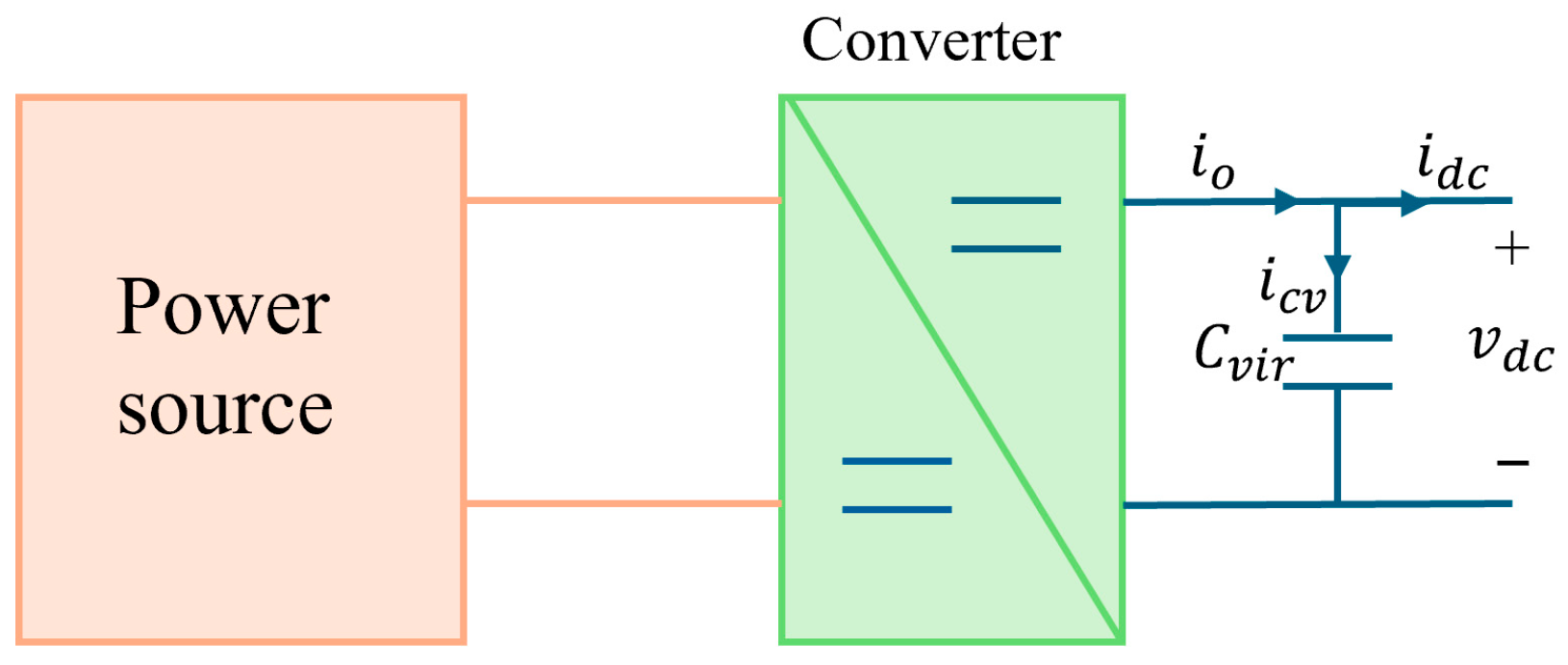
In DC microgrids, inertia helps to prevent sudden voltage fluctuations, and this inertia is primarily provided by the DC-link capacitors. When a rapid voltage changes occur, the capacitors absorb or release energy to stabilize the system. However, since DC microgrids typically use small capacitors, the inherent level of inertia is limited. To enhance this inertia, a virtual capacitor Cvir can be integrated into the system through the control of the converter as shown in Figure 3. This addition would effectively increase the system’s inertia, improving its ability to stabilize voltage fluctuations and enhance the overall performance of the DC microgrid [4,5]. In Figure 3, i o represents the converter output current, i d c is the current flowing to the DC bus, i c v is the additional virtual current, and C v i r is the capacitance of the virtual capacitor. The inertia current provided by the virtual capacitor can be expressed as:
i c v = C v i r d v d c * d t = i o i d c
To mitigate DC bus voltage oscillations, a damping current ( i d a m p ) is introduced to counteract the voltage fluctuation. As a result, Equation (3) can be rewritten as:
i c v = C v i r d v d c * d t = i o i d c i d a m p
From the previous equation, it is evident that v d c * is now determined by Equation (5). Consequently, the DC bus voltage will not respond quickly to sudden changes or disturbances, unlike in droop control. This approach enhances the stability of the system by reducing its sensitivity to rapid fluctuations.
v d c * = v n + 1 / C v i r i o i d c i d a m p   d t i d a m p = k d a m p ( v d c * v d c ) i o = v n v d c K d r o o p
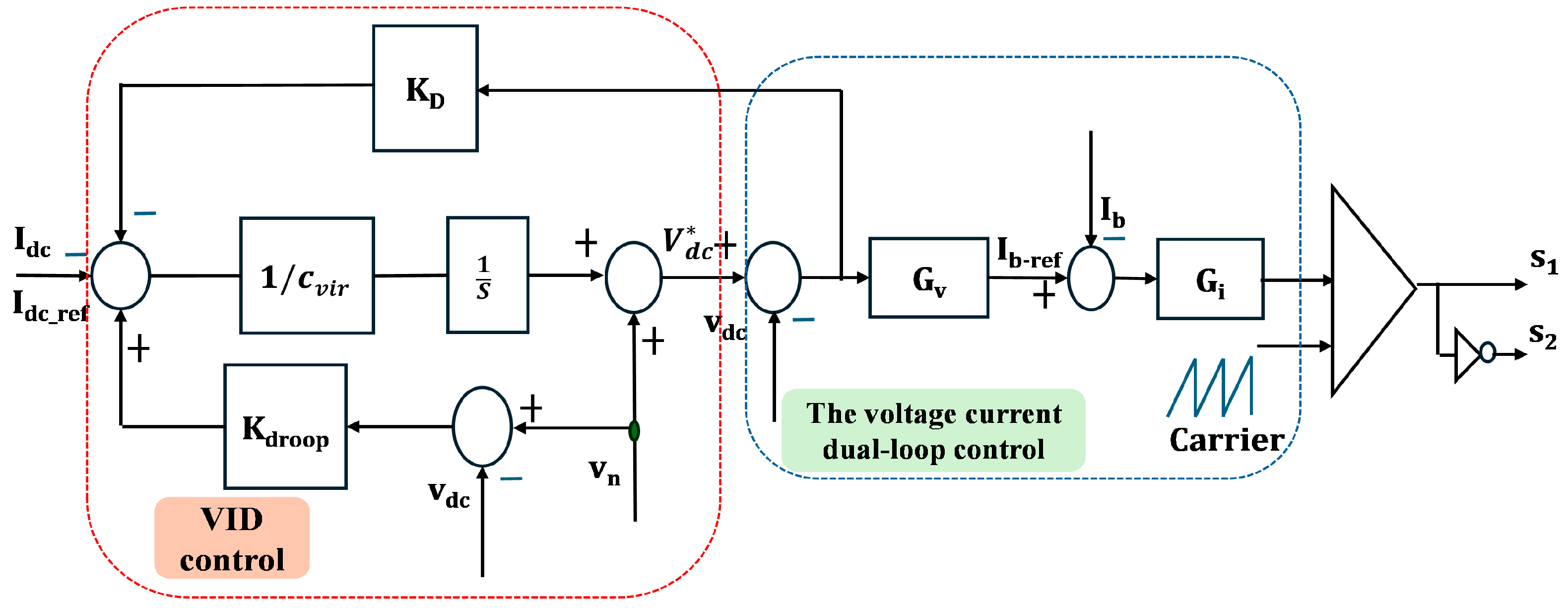
Once the reference value of the DC bus voltage is determined, a control loop is implemented to operate the converter of ESUs in a way that mimics the behavior of a VSG as shown in Figure 4. The control loop adjusts the converter output to match the dynamic performance of the VSG. This configuration utilizes a double-loop control system to regulate both voltage and current. The outer loop is responsible for voltage regulation, while the inner loop manages current regulation. The voltage PI controller is represented as Gv, and the current PI controller is denoted as Gi. These PI controllers ensure that the actual output consistently tracks the reference input, effectively eliminating steady-state error. The effectiveness of this control method depends on the proper design of the PI controllers and the selection of suitable parameter values (Cvir, KD). To achieve this, it is necessary to develop a dynamic model of the battery converter.

4.3. Determination of the Values of Cvir and kdamp

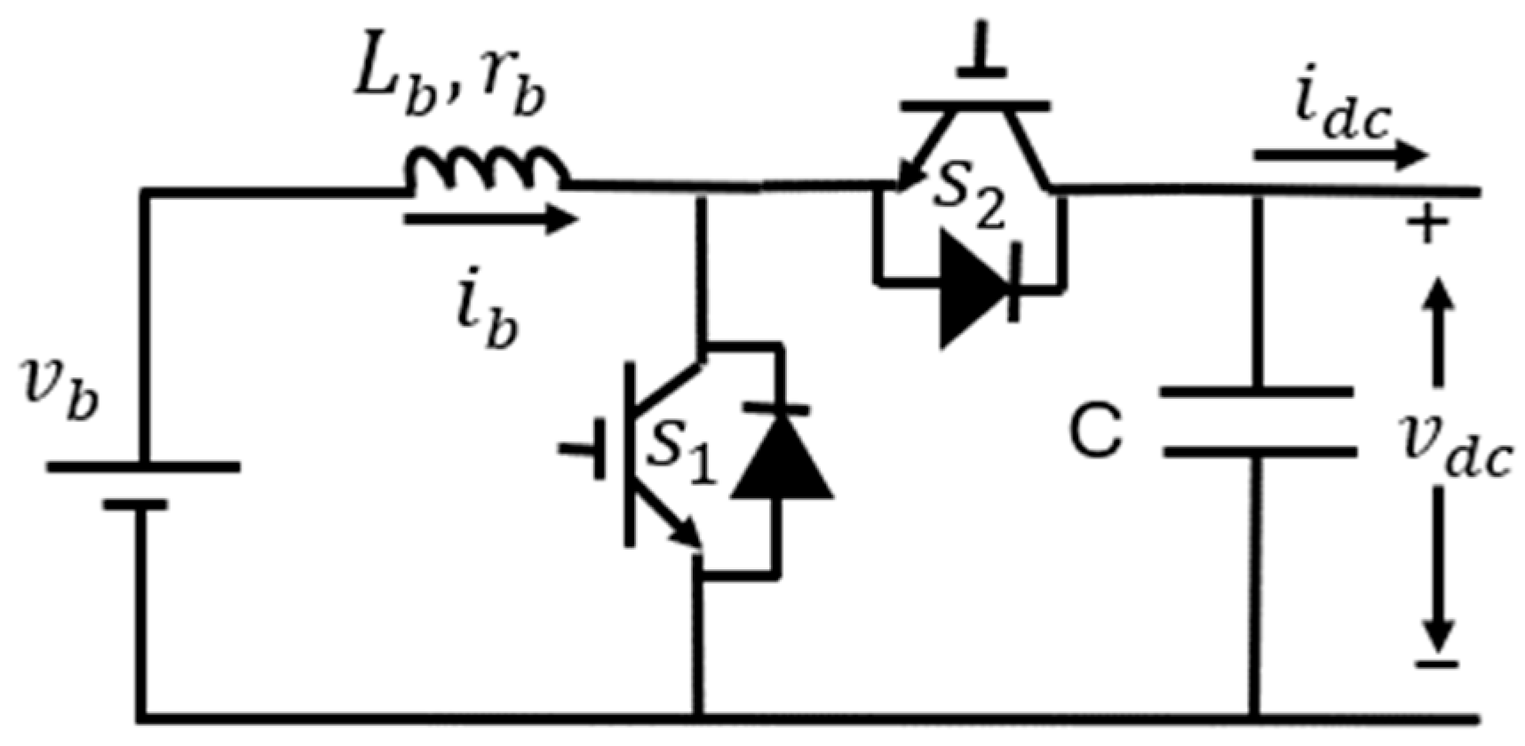
The dynamic model of a bidirectional converter is essential for determining the appropriate values of Cvir and kdamp. It allows for an accurate analysis of the system behavior under several conditions, aiding in fine-tuning control parameters for optimal performance. By building the dynamic model, the effects of these parameters on system response and stability can be better understood, ensuring that the system operates effectively and remains stable during disturbances. The average Linearized model of the bidirectional converter is obtained from the equivalent circuit shown in Figure 5, as follows:
C d Δ v d c d t = 1 D Δ i b I b Δ d Δ i d c
L b d Δ i b d t = Δ v b r b Δ i b 1 D Δ v d c + V d c Δ d
where Δ v b , Δ i b , and Δ d are the perturbations of the battery input voltage, the input battery current, and the duty, respectively. The fixed state values for these disturbances are V b , I b , and D, respectively. Additionally, the disturbances in the bus voltage and the output current are indicated by Δ v d c and Δ i d c , respectively, with steady state values are V d c and I d c , correspondingly. Applying the Laplace transform to Equation (6), Equation (7) and obtaining the transfer function between Δ i b (s) and Δd(s), Δ i b (s) and Δ i d c (s), Δ v d c (s) and Δd(s), Δ v d c (s) and Δ i d c (s), the following equations are obtained:
G i d = i b ( s ) d s = C V d c s + ( 1 D ) I b L C s 2 + R C s + ( 1 D ) 2
G i l = i b ( s ) i d c s = ( 1 D ) L C s 2 + R C s + ( 1 D ) 2
G v d = v d c ( s ) d s = L I b s R I b + ( 1 D ) V d c L C s 2 + R C s + ( 1 D ) 2
G v i = v d c ( s ) i d c s = L s R L C s 2 + R C s + ( 1 D ) 2
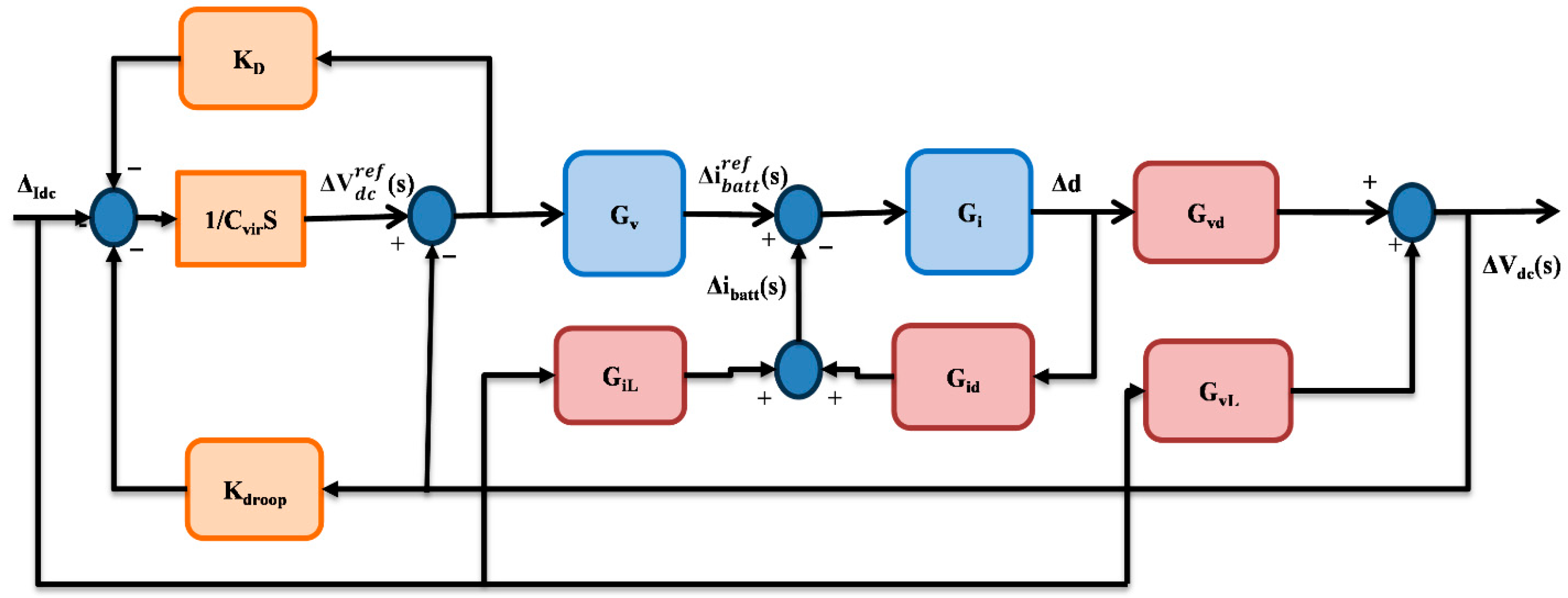
After deriving these functions, the small-signal model of virtual inertia and damping control for bidirectional converter can be obtained as illustrated in Figure 6. The closed-loop transfer function is then derived as shown in Equation (9).
t f s = v d c s i d c s = G v d G i G v G i i G v l C v i r s + k d a m p 1 + G i d G i + G i l G i G v d C v i r s + k d a m p c v i r s + k d a m p 1 + G i d G i + k d r o o p + c v i r s G v d G i G v G i i
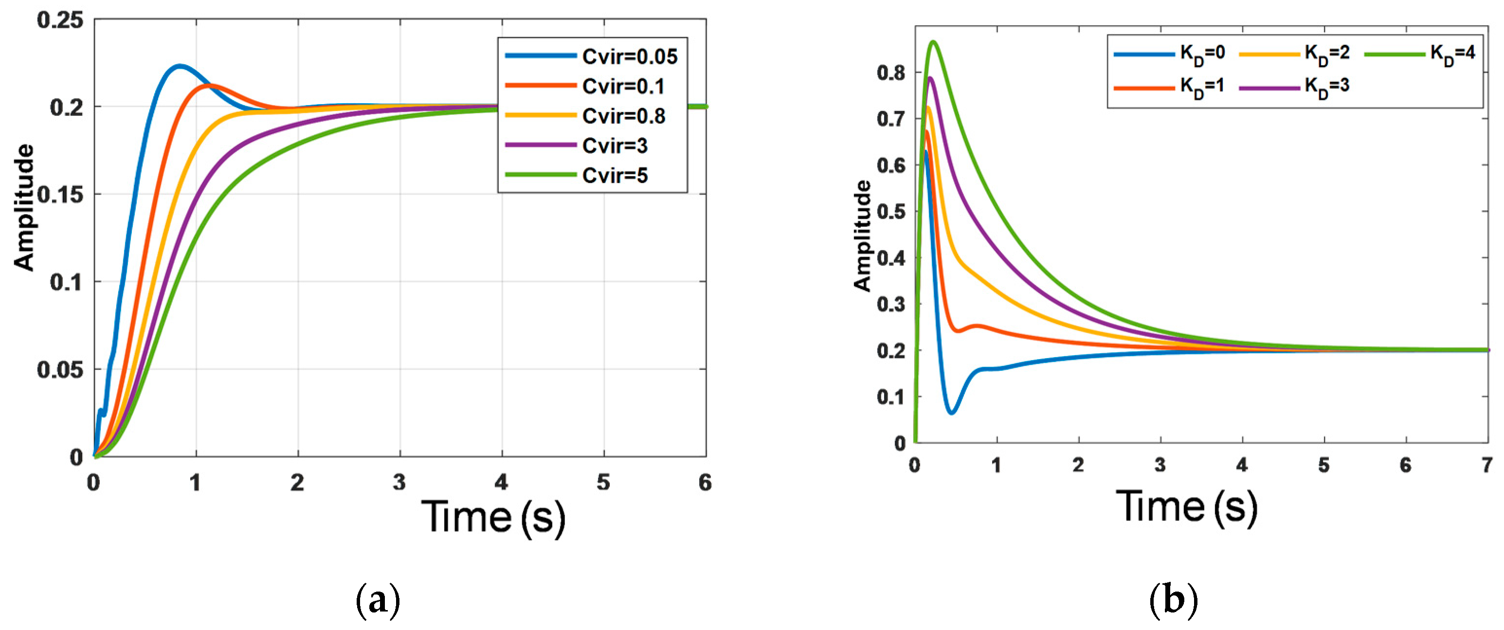
To study the effect of C v i r   a n d   k d a m p on the dynamic response of the system, the unit step response of t f s with different values of C v i r   a n d   k d a m p is obtained and results are illustrated in Figure 7. From Figure 7a, it can be observed that increasing the value of C v i r improves the dynamic response of the system, making it more responsive and accurate in reaching the desired output. However, this also results in a longer settling time, meaning the system takes more time to reach a stable state. On the other hand, increasing k d a m p reduces oscillations in the system, as shown in Figure 7b, which enhances system stability and reduces its tendency to fluctuate. However, higher damping also causes a longer settling time and can cause overshoot, where the system briefly exceeds the target value before stabilizing. Therefore, while increasing damping improves stability, it may also reduce system responsiveness in certain situations. After analyzing the impact of each parameter on the system, both Cvir and Kdamp were adjusted together to determine the optimal values. These values were selected based on steady state time required for stabilization and the acceptable level of overshoot.

4.4. Stability Analysis

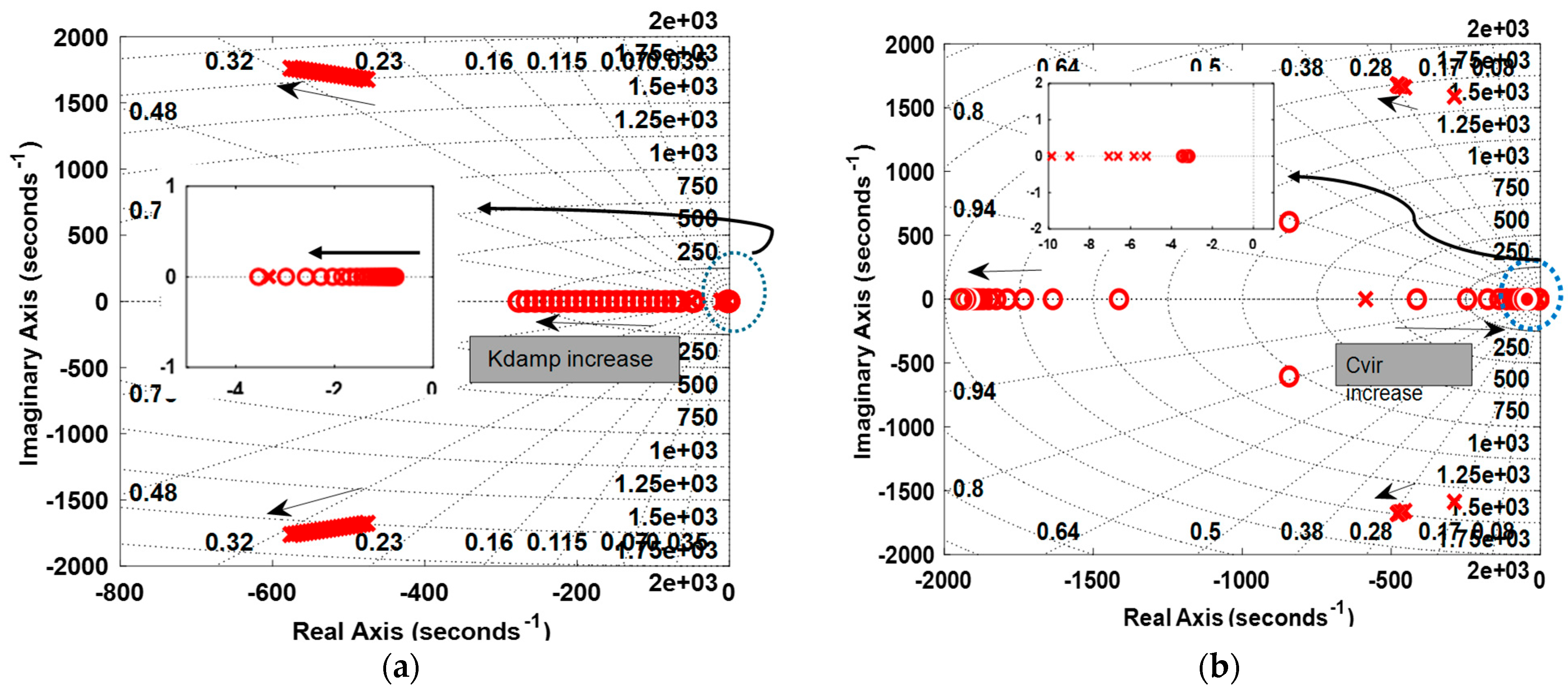
To assess the impact of control parameters on system stability, the trajectories of the dominant poles for the system are analyzed with the variation in the virtual inertia coefficient (Cvir) and damping coefficient (Kdamp). In Figure 8, the arrow direction indicates the movement of the poles and zeros which indicate in red symbol with the increase of Cvir and Kdamp. As illustrated in Figure 8a, the pole distribution as Kdamp increases from 0 to 100 and Cvir = 0.01. By increasing Kdamp, the poles shifts further to the left in the complex plane, indicating enhanced damping and improved system stability.
To evaluate the influence of Cvir, its value was varied from 0.01 to 10 while keeping Kdamp = 2, as depicted in Figure 8b. The results reveal that larger values of Cvir cause the poles to move closer to the imaginary axis, which can prolong the transient response time. However, the poles remain in the left half of the s-plane, confirming that the system maintains stability across the tested range.
These findings demonstrate that both Cvir and Kdamp play a critical role in shaping the dynamic behavior of the system. Proper tuning of these parameters enhances robustness against disturbances and ensures reliable operation within the desired performance specifications.

4.5. Case Study to Show the Effect of VIC on the System Response

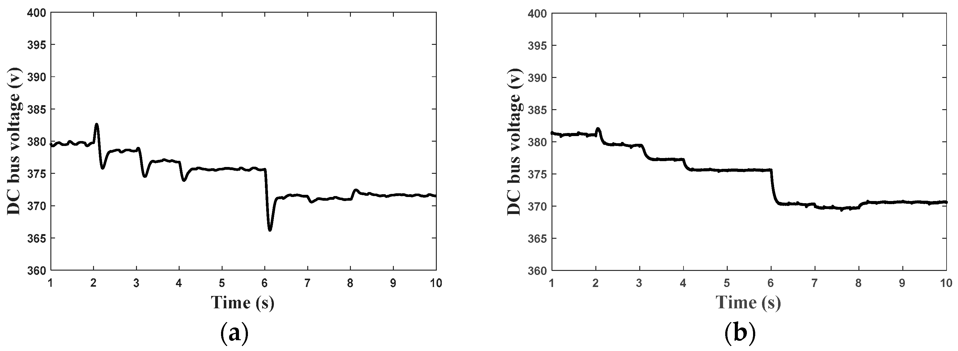
To verify the performance of the control method, a model of a single microgrid was developed, consisting of two batteries, a photovoltaic (PV) system, and a constant power load. Initially, the system was operated using droop control only. Later, the system was tested with a combination of virtual inertia control (VIC) and droop control. To demonstrate the impact of VIC on the system response, load and irradiation variations were introduced at t = 2 s, t = 3 s, t = 4 s, t = 6 s. Figure 9a shows the test results without virtual inertia control. With sudden changes in load and radiation, the dc bus voltage drops quickly due to the system’s small inertia. In contrast, Figure 9b illustrates the test results when the VIC is applied in combination with droop control. Thanks to VIC, the DC bus voltage gradually stabilizes to the new value without overshoot, and the transient time is extended. This confirms the effectiveness of VIC in enhancing the system’s inertia and improving overall stability.
From the results, it is clear that the battery plays a critical role in maintaining the power balance between generation and load, controlling the bus voltage, and improving the system’s dynamic performance. However, when the batteries reach full charge or discharge, or when the battery current reaches its maximum limit, control over the voltage is lost. To address this challenge, the concept of interconnecting microgrids was proposed to enhance the system’s dynamic performance, inertia and overall reliability. As a result, a multi-microgrid system was developed, consisting of several DC microgrids. The focus then shifted to coordinating the operation of the batteries to improve the overall system’s inertia, maintain battery lifespan and ensure high operational efficiency.

5. Secondary Control for Interconnected DC MGs

The secondary control proposed in this paper aims to ensure current sharing among parallel converters, balance the SoCs of energy storage units, and regulate the average voltage of the system.

5.1. Mathematical Model of the Proposed Coordinated Control of ESUs

To achieve these objectives, the secondary control generates an additional term Δ v i , which is incorporated into the droop equation, as given by Equation (10).
i o i = v n + Δ v i v d c R d i
The value of Δ v i is derived using a PI controller as in Equation (11), which receives the difference between two signals as input.
Δ v i = K P α a v a r g e α i + K I α a v a r g e α i d t
where K P and K I are the gains of PI controller.
These two signals are the state variable of each battery ( α i ) and the average state variable ( α a v a r g e ), and the state variable ( α i ) integrates SoC and current information of the battery unit as given by Equation (12).
α i = i b a t t i c b a t t i λ S O C i
where λ is a factor to control the speed of SOC balance, a higher value of λ results in a faster speed of SoC balancing, ibatti is the battery current and c b a t t i is the battery capacity.
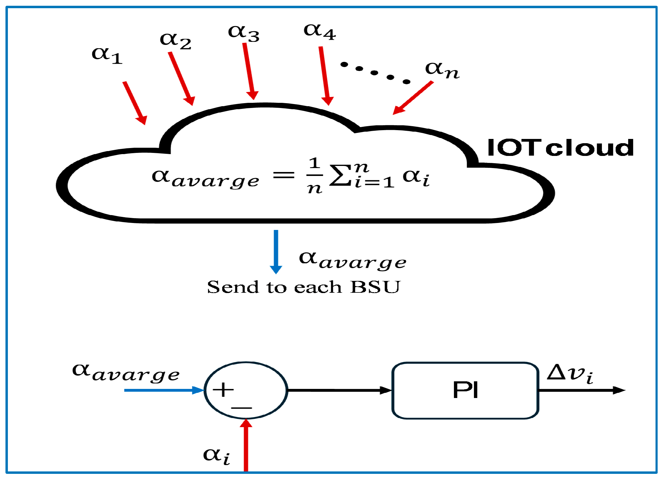
The average state variable α a v a r g e is obtained from the IoT cloud as shown in Figure 10 and is calculated according to Equation (13).
α a v a r g e = 1 n i = 1 n α i
where n is number of battery units.
To implement the proposed SoC balancing technique described in Equations (10)–(13), the ( α i ) value of each connected ESU is required to compute the average ( α a v a r g e ) . Unlike the method in [6], which involves direct communication of ( α i ) values between ESUs, the proposed IoT-based hierarchical control simplifies the process. Each ESU only needs to report its ( α i ) value to the cloud, where the computation of output ( α a v a r g e ) for all ESUs is performed. The computed result is then sent back to the individual ESUs. This coordination, combining IoT communication with the proposed technique, is summarized in Figure 10, which illustrates the in-cloud computation process along with the data received and transmitted. The proposed IoT-based SoC balancing solution for multiple microgrids offers several key advantages over other techniques:
  • Scalability: The system is suitable for a wide range of applications, from small residential microgrids to large-scale utility systems.
  • Adaptability: It accommodates varying ESU capacities and configurations without requiring significant modifications to the system design.
  • Robustness: It maintains overall system performance even in case of faults or disconnections of individual ESUs.
  • Accuracy: The power-sharing algorithm ensures equitable energy contributions from each ESU.
  • Efficiency: By optimizing energy storage utilization, the system enhances overall energy efficiency and reduces operational costs.

5.2. Discussion of Control Objectives Achievement

To demonstrate the effectiveness of this method in facilitating cooperation between batteries and maintaining balance among SoCs, a mathematical approach will be presented. This approach emphasizes the importance of accurately estimating the SoC, which is typically updated using the Coulomb Counting method, as described in Equation (14).
S O C i = S O C o 1 c b a t t i i b a t t i d t
where S O C o and c b a t t i are initial value of SOC and the capacity of battery.
Once the PI controller adjusts α i to match α a v a r g e , it means that the variables of all batteries have become equal. As a result, the two variables are equal as follows:
α i = α j i b a t t i c b a t t i λ S o C i = i b a t t j c b a t t j λ S o C j
By differentiating Equation (14) as shown in Equation (16), and then substituting the result into Equation (15), the following relations are derived.
d S o C i d t = i b a t t i c b a t t i
d S o C i d t λ S o C i = d S O C j d t λ S o C j
d S o C i d t d S o C j d t = λ ( S o C i S o C j )
d d t ( S o C i S o C j ) = λ ( S o C i S o C j )
d ( S o C i S o C j ) ( S o C i S o C j ) = λ d t
x t = x o e λ t   w h e r e   x = S o C i S o C j   a n d   x o = S o C i o S o C j o
By integrating the equation, it is evident that the solution represents a decreasing exponential function. This indicates that the difference between the SoCs will gradually diminish until equilibrium is achieved. The rate at which equilibrium is reached depends on the value of λ, as illustrated from the output current in Figure 11a and ΔSoC in Figure 11b. An increase in λ results in faster system convergence to equilibrium. However, this comes at the cost of higher output current from the converter. Therefore, it is essential to determine an optimal value for λ to ensure that the converter’s maximum output current is not exceeded.

5.3. Determination of the Range for λ

Using Equation (15), the permissible range of λ values can be derived and is provided in Equation (22). To evaluate the worst-case scenario, two batteries are assumed to operate in discharge mode: one battery is fully discharged, while the other is supplying the load. Under these conditions, the value of λ is calculated using Equation (23). This equation shows that λ is influenced by the total load current, the battery capacity, and the ΔSOCij value.
λ = i b a t t i c b a t t i i b a t t j c b a t t j S O C i S O C j
λ i l o a d s c b a t t i Δ s o c i j     i f   i l o a d s > 0         d i s c h a r g i n g   m o d e
λ i l o a d s c b a t t j Δ s o c i j     i f   i l o a d s < 0                   c h a r g i n g   m o d e

5.4. Complete Control Block Diagram of ESU

The detailed control algorithm for the battery energy-storage system is presented in Figure 12. This figure illustrates the integration of the primary droop control with VID control and the proposed secondary control. The additional voltage term (Δvi) is generated as per Equation (11) and is supplied to the primary droop control to compute the reference DC current, i d c r e f , according to Equation (10). Subsequently, the adjusted voltage term Δ v i * is determined based on the VID control. The voltage control loop then tracks this reference value to generate the battery’s output current reference. Similarly, the current control loop follows its reference and generates two complementary Pulse Width Modulation (PWM) signals for the battery converter.

6. Results and Discission

To evaluate the performance of the proposed control system, a four-DCMGs system, as shown in Figure 1 is tested in MATLAB (R2021a)/Simulink with several case studies. The system parameters are provided in Table 1. These case studies are categorized into two main scenarios:
Scenario 1: This scenario investigates the ability of the secondary control to achieve balance among the ESUs. To evaluate this, the capacities of the ESUs are scaled from 100 Ah to 0.2 Ah. This scaling allows to observe whether the secondary control can effectively balance the ESUs under varying conditions.
Scenario 2: This scenario demonstrates the impact of VIC on improving the system’s transient response. For this evaluation, the battery is represented by its actual capacity of 100 Ah to assess how the VID control enhances the system’s ability to respond to sudden changes or disturbances.
  • The first scenario
This scenario is dedicated to evaluate the ability of the secondary control system to maintain SoC balance and load sharing between the converters. Therefore, several case studies will be investigated to evaluate its performance.
Case 1: This case tests the effectiveness of the secondary control system in maintaining balance between the batteries during both discharging and charging modes.
In the discharging mode, ESUs with identical capacities of 0.2 Ah were used, but the batteries started with different initial SoC. When the output power from RESs was lower than the load demand, the batteries will be in the discharging mode to supply the required power, as shown in Figure 13. Due to the differences in SoC, the secondary control system ensured that batteries with a higher SoC discharged at a higher current, while those with a lower SoC discharged at a lower current. This process continued until equilibrium was achieved, where all batteries began discharging at the same current value.
Subsequently, the control system was tested in charging mode, assuming that the load demand was lower than the generated power, causing the batteries to enter charging mode. As illustrated in Figure 14, the control system effectively minimized the SoC disparity between the batteries. The battery with a lower SoC was charged with a higher current, while the battery with a higher SoC received a lower charging current.
Case 2: Demonstrates the effect of λ on the speed of SOC balancing.
This case is similar to the previous one in charging mode but uses a larger value of λ, set to 5. As shown in Figure 15, the batteries reached equilibrium more quickly with this higher λ value. However, this faster equilibrium was achieved at the cost of a significant difference in the initial output currents from the ESUs. When λ was increased from 2 to 5, the initial charging currents of ESUs (1 and 2) rose from 30 A and 50 A to 35 A and 65 A, respectively. Therefore, it is crucial to carefully select the λ value to ensure that the current remains within permissible limits.
Case 3: Tests the performance of secondary control when using ESUs with different capacities.
In this case, ESUs with different capacities and initial SOC were used. The capacities of the ESUs are given as C2 = C3 = 4C1 and C4 = 2C1, where C1 = 0.2 Ah. The batteries operate together in charging mode, as shown in Figure 16. The results indicate that the control system successfully achieved equilibrium between the SoCs of the batteries. After equilibrium was reached, each battery charged according to its respective capacity, as evidenced by the current profiles in Figure 16b. This demonstrates that the control system adjusted the charging process to ensure that each ESU received the correct amount of charge relative to its capacity.
  • The second scenario
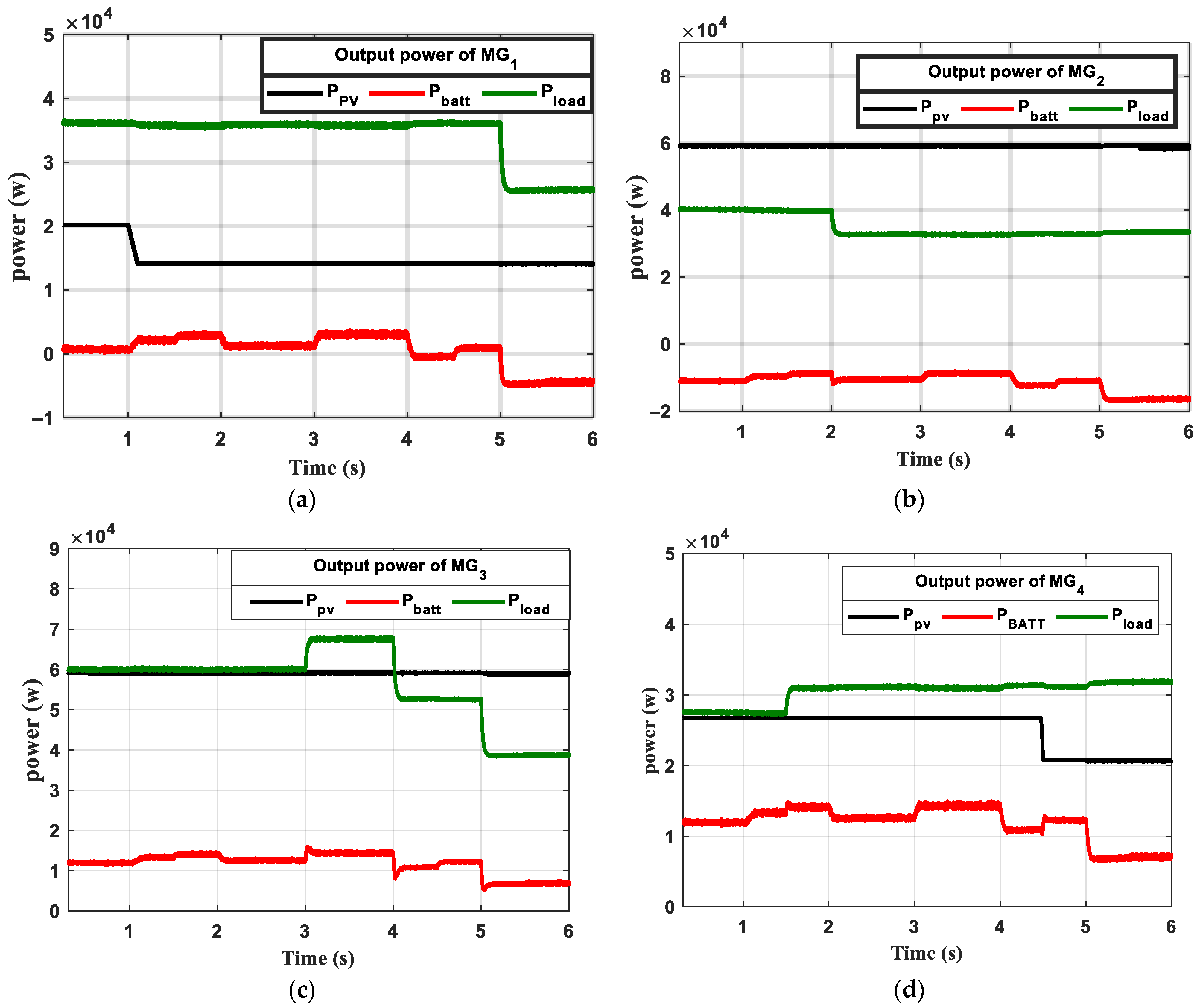
This scenario investigates the impact of VIC on the system’s response. To analyze this, variations in both load and irradiation in each MG are considered, as shown in Figure 17. Figure 17a illustrates the variation in PV output power and load power in MG1, while Figure 17b shows the PV output power and load power in MG2. For MG3 and MG4, the PV power and load power are depicted in Figure 17c and Figure 17d, respectively. These variations enable the examination of system responses to changes in VIC, offering deeper insights into its performance and stability under dynamic operating conditions. To achieve this, it is essential for the ESUs to reflect their true capacity. In this case, all ESUs are assumed to have the same capacity of 100 Ah. As a result, the effect of the secondary control becomes evident through the currents, since changes in the SOC occur slowly, particularly when operating over short time intervals, such as seconds.
Firstly, the states of the system will be presented through the cloud of the IoT in the ThingSpeak output channel, as shown in Figure 18 The states are ( α 1 of MG1, α 2 of MG2, α 3 of MG3 and α 4 of MG4). Accordingly, the updated α a v a r g e is calculated in real-time on the cloud in M-file and shown through another ThingSpeak input channel as depicted in Figure 18.
Case 1: System response to variations in load and irradiation with and without VIC.
In this case, the effect of VIC on system performance is evaluated by varying the loads and irradiation levels in each MG at different time intervals, as shown in Figure 17. By analyzing the resulting voltage profiles of each MG and comparing them to those observed in the absence of VIC, the influence of VIC on voltage regulation and system stability can be clearly assessed. As seen in Figure 19b, when there are variations in load or irradiation, the voltage fluctuates rapidly, often exhibiting overshoot. This behavior is due to representing the droop control by a static equation, which can cause significant voltage deviations during substantial changes in load or irradiation. Such fluctuations may endanger sensitive loads or trigger protective devices. In contrast, when VIC is implemented, the voltage adjustments are more gradual and smoother, steadily transitioning toward the new set point, as shown in Figure 19e. As a result, voltage deviations are minimized, improving system stability and providing better protection against undesirable fluctuations, which leads to more reliable and efficient operation. Additionally, the impact of secondary control is reflected in the current profiles, where each battery contributes according to its individual SOC, as shown in Figure 19a,d. This ensures that the batteries compensate for any imbalance between load and generation, maintaining proper energy distribution and overall system balance. From Figure 19c,f, it can be observed that the SOC of all batteries remains almost constant, as the operational period is very short.
Case 2: The effect of kdamp and Cvir.
This case demonstrates the effect of kdamp and Cvir on the voltage of the buses. In Figure 20a,b, when Cvir = 0.1, an overshoot in the voltage is observed. However, when Cvir = 0.5 is applied, the overshoot disappears. This indicates that as Cvir increases, the system inertia also increases, which helps to provide damping and stabilize the system. Furthermore, by varying the value of kdamp, as seen in Figure 20b,c, the voltage reaches a higher value, when the value of kdamp increases, and starts to move slowly to return to its original value. This indicates that an increase in kdamp causes a greater overshoot and extends the steady-state settling time.
Case 3: The effect of VIC during fault
This case demonstrates the effect of VIC during a fault occurrence. A fault was introduced at Bus 2 with a resistance of 0.5 ohms at t = 0.5 s, lasting for 0.1 s, and was cleared at t = 0.6 s. As shown in Figure 21a, the voltage at Bus 3 and Bus 4 remained above 360 V, indicating that these buses were unaffected by the fault. The voltage at Bus 1 was slightly affected, with a drop that did not fall below 350 V. However, since the fault occurred at Bus 2, its voltage dropped to 310 V. Once the fault was cleared, all voltages returned smoothly to their normal levels without any overshoot. In terms of currents and SOC, as shown in Figure 21b,c, the involvement of VIC during the transient period caused irregular current distribution between the batteries, leading to a temporary imbalance between SOC3 and SOC4. However, after the fault was cleared, the secondary control system restored the balance between the batteries.
To assess the performance of VIC, results were also taken for the case where VIC was not used. As shown in Figure 21d, all buses were affected by the fault, with all voltages dropping below 360 V. After the fault was cleared, a significant voltage overshoot occurred before the system stabilized. Since no control effect introduced during the transient period, the rate of change in all currents remained nearly constant, which maintained the balance between the SOCs of all batteries, even during the fault, as shown in Figure 21e,f. These results indicate that VIC increased the system’s inertia, enabling it to better withstand fault conditions.
  • Comparison with the pervious control scheme
A comparison between the proposed control scheme and existing schemes is presented in Table 2. The performance of the previous schemes reveals limitations in enhancing the transient response of multi-MGs, maintaining power sharing between converters, and balancing the SoCs of all ESUs. In contrast, the proposed control scheme effectively addresses these challenges. Additionally, it enables real-time monitoring of the system and can handle all MG configurations, such as radial, mesh, and ring topologies.

7. Conclusions

In this research, a hierarchical control strategy for MMGs was proposed to enhance system inertia. This was achieved by fostering cooperation between the batteries in each microgrid to address the imbalance between load and generation. As a result, when sudden changes occur in any microgrid, all ESUs collaborate to balance load and generation, preventing rapid voltage fluctuations and improving system inertia. Several operating cases were studied to assess the performance of the control strategy, and the key findings are as follows:
  • Secondary Control: The secondary control successfully enabled cooperation between ESUs, which was evident during both charging and discharging, regardless of whether the ESUs had the same or different capacities.
  • Primary Control: The primary control significantly improved the dynamic response of the system during load changes and varying irradiance conditions.
  • Effect of Parameters: The effects of the parameters Cvir and kdamp were studied. It was observed that increasing the value of Cvir improved voltage regulation, although the system required more time to stabilize. For the parameter kdamp, a slower system response was observed, along with an increase in overshoot.
  • Impact of λ: The parameter λ was also examined, and higher values of λ resulted in quicker balancing between ESUs, although this negatively impacted the output current of the converters.
  • IoT integration: IoT-based centralized coordination of ESUs improved inertia and enhanced DCMMG system stability through real-time data exchange, monitoring and decision-making.
In conclusion, the proposed control method demonstrated significant potential in enhancing both the static and dynamic responses of the system. Future work will aim to extend the control strategy to support heterogeneous energy storage technologies, develop a hardware prototype for experimental validation, and adapt the system for seamless integration with AC microgrids.

Author Contributions

Conceptualization, E.K.B. and A.M.A.; methodology, E.K.B. and D.M.Y.; software, E.K.B. and A.E.E.G.; validation, G.E.M.A. and X.L.; formal analysis, E.K.B., D.M.Y. and A.M.A.; investigation, E.K.B. and A.E.E.G.; resources, D.M.Y. and X.L.; data curation, E.K.B. and A.M.A.; writing—original draft preparation, E.K.B. and A.E.E.G.; writing—review and editing, D.M.Y., A.M.A., G.E.M.A. and X.L.; visualization, A.M.A., A.E.E.G. and G.E.M.A.; supervision, D.M.Y., A.M.A., G.E.M.A. and A.E.E.G.; project administration, D.M.Y.; funding acquisition, D.M.Y. and X.L. All authors have read and agreed to the published version of the manuscript.

Funding

This work is based upon work sponsored by the Science, Technology and Innovation Funding Authority (STIFA), Egypt under grant number 44193; and the National Key Research and Development Program of China under Grant number 2022YFE0120400.

Data Availability Statement

The data presented in this study are available upon request.

Conflicts of Interest

The authors declare no conflicts of interest.

References

  1. Han, Y.; Ning, X.; Yang, P.; Xu, L. Review of power sharing, voltage restoration and stabilization techniques in hierarchical controlled DC microgrids. IEEE Access 2019, 7, 149202–149223. [Google Scholar] [CrossRef]
  2. Ramadan, R.; Huang, Q.; Zalhaf, A.S.; Bamisile, O.; Li, J.; Mansour, D.E.A.; Lin, X.; Yehia, D.M. Energy Management in Residential Microgrid Based on Non-Intrusive Load Monitoring and Internet of Things. Smart Cities 2024, 7, 1907–1935. [Google Scholar] [CrossRef]
  3. Ibrahim, N.N.; Jamian, J.J.; Rasid, M.M. Optimal multi-objective sizing of renewable energy sources and battery energy storage systems for formation of a multi-microgrid system considering diverse load patterns. Energy 2024, 304, 131921. [Google Scholar] [CrossRef]
  4. Yokomizu, Y.; Yehia, D.M.; Iioka, D.; Matsumura, T. Formulated representation for upper limitation of deliverable power in low-voltage DC distribution system. IEEJ Trans. Power Energy 2011, 131, 362–368. [Google Scholar] [CrossRef]
  5. Modu, B.; Abdullah, M.P.; Sanusi, M.A.; Hamza, M.F. DC-based microgrid: Topologies, control schemes, and implementations. Alex. Eng. J. 2023, 70, 61–92. [Google Scholar] [CrossRef]
  6. Ahmad, S.; Shafiullah, M.; Ahmed, C.B.; Alowaifeer, M. A Review of Microgrid Energy Management and Control Strategies. IEEE Access 2023, 11, 21729–21757. [Google Scholar] [CrossRef]
  7. Belal, E.K.; Yehia, D.M.; Azmy, A.M. Adaptive droop control for balancing SOC of distributed batteries in DC microgrids. IET Gener. Transm. Distrib. 2019, 13, 4667–4676. [Google Scholar] [CrossRef]
  8. Xu, J.; Liu, W.; He, G. An Adaptive Virtual Inertial Control Strategy for DC Distribution Networks. Energies 2024, 17, 2401. [Google Scholar] [CrossRef]
  9. Liu, J.; Miura, Y.; Ise, T. A comparative study on damping methods of virtual synchronous generator control. In Proceedings of the 2019 21st European Conference on Power Electronics and Applications, EPE 2019 ECCE Europe, Genova, Italy, 3–5 September 2019; Institute of Electrical and Electronics Engineers Inc.: New York, NY, USA, 2019. [Google Scholar]
  10. Swaminathan, G.V.; Periasamy, S.; Lu, D.D.C. Capacitor Current Control Based Virtual Inertia Control of Autonomous DC Microgrid. IEEE Trans. Ind. Electron. 2023, 70, 6908–6918. [Google Scholar] [CrossRef]
  11. Zeng, Y.; Jiang, S.; Konstantinou, G.; Pou, J.; Zou, G.; Zhang, X. Multi-Objective Controller Design for Grid-Following Converters with Easy Transfer Reinforcement Learning. IEEE Trans. Power Electron. 2025, 40, 6566–6577. [Google Scholar] [CrossRef]
  12. Yin, Z.; Xue, S.; Wang, Z.; Yu, F.; Chen, H. Flexible Droop Coefficient-Based Inertia and Voltage Cascade Control for Isolated PV-Battery DC Microgrid. Energies 2022, 15, 9318. [Google Scholar] [CrossRef]
  13. Li, C.; Yang, Y.; Dragicevic, T.; Blaabjerg, F. A New Perspective for Relating Virtual Inertia with Wideband Oscillation of Voltage in Low-Inertia DC Microgrid. IEEE Trans. Ind. Electron. 2022, 69, 7029–7039. [Google Scholar] [CrossRef]
  14. Samanta, S.; Mishra, J.P.; Roy, B.K. Virtual DC machine: An inertia emulation and control technique for a bidirectional DC-DC converter in a DC microgrid. IET Electr. Power Appl. 2018, 12, 874–884. [Google Scholar] [CrossRef]
  15. Wu, H.; Ruan, X.; Yang, D.; Chen, X.; Zhao, W.; Lv, Z.; Zhong, Q.C. Small-Signal Modeling and Parameters Design for Virtual Synchronous Generators. IEEE Trans. Ind. Electron. 2016, 63, 4292–4303. [Google Scholar] [CrossRef]
  16. Zhu, X.; Meng, F.; Xie, Z.; Yue, Y. An Inertia and Damping Control Method of DC-DC Converter in DC Microgrids. IEEE Trans. Energy Convers. 2020, 35, 799–807. [Google Scholar] [CrossRef]
  17. Yehia, D.M.; Numair, M.; Mansour, D.A. Novel IoT-Based Droop Control for Battery SoC Balancing among Multiple Microgrids. IEEE Trans. Smart Grid 2024, 15, 1304–1316. [Google Scholar] [CrossRef]
  18. Nahas, E.W.; Mansour, D.A.; Abd el-Ghany, H.A.; Dawoud, S.M.; Azmy, A.M. A novel IoT-based adaptive protection scheme for active DC distribution systems incorporating networked microgrids. Electr. Power Syst. Res. 2025, 238, 111113. [Google Scholar] [CrossRef]
  19. Su, J.; Li, K.; Xing, C.; Li, Y.; Yu, J. A simplified consensus-based distributed secondary control for battery energy storage systems in DC microgrids. Int. J. Electr. Power Energy Syst. 2024, 155, 109627. [Google Scholar] [CrossRef]
  20. Sharma, S.; Iyer, V.M.; Bhattacharya, S.; Zou, K. New Mesh Configurations with Decentralized Droop Control Method for DC Microgrids. IEEE Trans. Ind. Electron. 2024, 71, 560–571. [Google Scholar] [CrossRef]
  21. Xie, C.; Wei, M.; Luo, D.; Yang, L. Energy balancing strategy for the multi-storage islanded DC microgrid based on hierarchical cooperative control. Front. Energy Res. 2022, 12, 1390621. [Google Scholar] [CrossRef]
  22. Alam, M.S.; Al-Ismail, F.S.; Shafiullah, M.; Hossain, M.I.; Shahriar, M.S.; Mostafa, S.G.; Abido, M.A. A New Voltage Compensation and State of Charge-Assisted Power Sharing Strategy for DC Microgrids. Arab. J. Sci. Eng. 2024, 49, 15971–15983. [Google Scholar] [CrossRef]
  23. Zeng, Y.; Zhang, Q.; Liu, Y.; Guo, H.; Zhang, F.; You, S. Distributed Unified Controller Design for Parallel Battery Storage System in DC Shipboard Microgrid. IEEE Trans. Power Syst. 2024, 39, 546–563. [Google Scholar] [CrossRef]
  24. Moghimi, M.; Liu, J.; Jamborsalamati, P.; Rafi, F.H.M.; Rahman, S.; Hossain, J.; Stegen, S.; Lu, J. Internet of Things Platform for Energy Management in Multi-Microgrid System to Improve Neutral Current Compensation. Energies 2018, 11, 3102. [Google Scholar] [CrossRef]
  25. Sheba, M.A.; Mansour, D.A.; Abbasy, N.H. A new low-cost and low-power industrial internet of things infrastructure for effective integration of distributed and isolated systems with smart grids. IET Gener. Transm. Distrib. 2023, 17, 4554–4573. [Google Scholar] [CrossRef]
  26. Sangam, S.V.; Kulkarni, S.S.; Jambotkar, A.P.C.K. Smart Grid Communication Protocols. Int. J. Trend Sci. Res. Dev. 2019, 3, 335–337. [Google Scholar] [CrossRef]
  27. Zhou, B.; Zou, J.; Chung, C.Y.; Wang, H.; Liu, N.; Voropai, N.; Xu, D. Multi-microgrid Energy Management Systems: Architecture, Communication, and Scheduling Strategies. J. Mod. Power Syst. Clean Energy 2021, 9, 463–476. [Google Scholar] [CrossRef]
  28. Zhi, N.; DIng, K.; Du, L.; Zhang, H. An SOC-Based Virtual DC Machine Control for Distributed Storage Systems in DC Microgrids. IEEE Trans. Energy Convers. 2020, 35, 1411–1420. [Google Scholar] [CrossRef]
  29. Hosseinipour, A.; Hojabri, H. Virtual inertia control of PV systems for dynamic performance and damping enhancement of DC microgrids with constant power loads. IET Renew. Power Gener. 2018, 12, 430–438. [Google Scholar] [CrossRef]
  30. Wu, W.; Chen, Y.; Luo, A.; Zhou, L.; Zhou, X.; Yang, L.; Dong, Y.; Guerrero, J.M. A Virtual Inertia Control Strategy for DC Microgrids Analogized with Virtual Synchronous Machines. IEEE Trans. Ind. Electron. 2017, 64, 6005–6016. [Google Scholar] [CrossRef]
Figure 1. Configuration of Multiple DCMGs.
Smartcities 08 00166 g001
Figure 2. Hierarchical control level architecture.
Smartcities 08 00166 g002
Figure 3. Virtual capacitor of DC microgrid.
Smartcities 08 00166 g003
Figure 4. Control loop of bidirectional converter.
Smartcities 08 00166 g004
Figure 5. Equivalent circuit of bidirectional converter.
Smartcities 08 00166 g005
Figure 6. Dynamic model of bidirectional converter.
Smartcities 08 00166 g006
Figure 7. Result of step response of closed loop transfer function with different value of Cvir, Kdamp. (a) Results with different Cvir, (b) Results with different kdamp.
Smartcities 08 00166 g007
Figure 8. Eigen values of closed loop transfer function with different value of Cvir, kdamp. (a) Cvir change and (b) kdamp change.
Smartcities 08 00166 g008
Figure 9. Simulation results of bus voltage under using droop control only and droop with VIC. (a) result using droop control, (b) result using droop and VIC.
Smartcities 08 00166 g009
Figure 10. Proposed SoC balancing algorithm for IoT cloud platforms.
Smartcities 08 00166 g010
Figure 11. Results showing the effect of λ on the current output and ΔSOC (a) Output current, (b) ΔSOC.
Smartcities 08 00166 g011
Figure 12. Complete control block diagram of bidirectional ESU converter.
Smartcities 08 00166 g012
Figure 13. Results in discharging mode. (a) SOCs, (b) current, (c) bus voltage.
Smartcities 08 00166 g013
Figure 14. Results in charging mode. (a) SOCs, (b) current, (c) bus voltage.
Smartcities 08 00166 g014
Figure 15. Results in charging mode with large value of λ. (a) SOCs, (b) current, (c) bus voltage.
Smartcities 08 00166 g015
Figure 16. Results for ESUs with different capacities. (a) SOCs, (b) current, (c) bus voltage.
Smartcities 08 00166 g016
Figure 17. Power in each MG. (a) MG1, (b) MG2, (c) MG3, (d) MG4.
Smartcities 08 00166 g017
Figure 18. ThingSpeak output/input channel public view. (a) state of MG1 sent to cloud. (b) state of MG2 sent to cloud. (c) state of MG3 sent to cloud. (d) state of MG4 sent to cloud. (e) adaptive value of α a v a r g e received in MATLAB/Simulink.
Smartcities 08 00166 g018aSmartcities 08 00166 g018b
Figure 19. Results with and without using VIC. (a) batteries current, (b) buses voltage, (c) batteries, without using VIC. (d) batteries current, (e) buses voltage, (f) SOCs of batteries, with using VIC.
Smartcities 08 00166 g019aSmartcities 08 00166 g019b
Figure 20. Voltage waveform with different values of kdamp and Cvir. (a) kdamp = 0.5 and Cvir = 0.1, (b) kdamp = 0.5 and Cvir = 0.5, (c) kdamp = 2 and Cvir = 0.5.
Smartcities 08 00166 g020
Figure 21. Effect of fault at bus 2 with and without VIC (a) Buses voltages (b) The batteries current and (c) the batteries SOC with VIC. (d) The buses voltage, (e) The batteries current and (f) The batteries SOC without VIC.
Smartcities 08 00166 g021
Table 1. PARAMETERS of the SYSTEM.
MG1MG2MG3MG4
PV array20 kW at 25 °C and 1000 W/m260 kW at 25 °C and 1000 W/m260 kW at 25 °C and 1000 W/m230 kW at 25 °C and 1000 W/m2
PV converter L P V = 0.2 mH, r P V = 0.002 Ω, C P V = 0.003 mF L P V   = 0.5 mH,
r P V   = 0.005 Ω, C P V   = 0.003 mF
L P V   = 0.5 mH, r P V   = 0.005 Ω, C P V   = 0.003 mF L P V   = 0.25 mH, r P V   = 0.0025 Ω, C P V   = 0.003 mF
Battery unit v b = 110 V,
capacity = 100 Ah
Battery converterP = 30 kW, L b   = 0.373 mH, r b   = 0.005 Ω, C = 0.002 F
Voltage control of B-DCKp = 3, Ki = 100
Current control of B-DCKp = 0.005, Ki = 0.1
Cvir = 0.5, kdamp = 0.5, Rd = 0.2
Table 2. Comparison with the previous work.
SchemeImproved Transient ResponseEffective Power SharingMaintain SOC BalanceApplicable for Any Network ConfigurationComplexity
[8]YESYESNONOLess
[17]NOYESYESYESLess
[19]NOYESYESYESModerate
[20]NOYESYESNOComplex
[23]NOYESYESYESComplex
[28]YESYESYESNOComplex
ProposedYESYESYESYESLess
Disclaimer/Publisher’s Note: The statements, opinions and data contained in all publications are solely those of the individual author(s) and contributor(s) and not of MDPI and/or the editor(s). MDPI and/or the editor(s) disclaim responsibility for any injury to people or property resulting from any ideas, methods, instructions or products referred to in the content.