Article

Intelligent Rebar Optimization Framework for Urban Transit Infrastructure: A Case Study of a Diaphragm Wall in a Singapore Mass Rapid Transit Station

1
Department of Architectural Engineering, Kyung Hee University, Yongin-si 17104, Republic of Korea
2
Department of R&D, Earth Turbine, Co., Ltd., Daegu 41507, Republic of Korea
*
Author to whom correspondence should be addressed.
Smart Cities 2025, 8(4), 130; https://doi.org/10.3390/smartcities8040130
Submission received: 30 June 2025 / Revised: 1 August 2025 / Accepted: 6 August 2025 / Published: 7 August 2025
(This article belongs to the Topic Sustainable Building Development and Promotion)

Abstract

Highlights

What are the main findings?
  • Development of an intelligent, AI-assisted framework that integrates BIM perspective and metaheuristic algorithms for rebar optimization in diaphragm wall construction.
  • Demonstrated reductions in rebar usage, cutting waste, embodied carbon, and costs, while enhancing constructability through intelligent allocation of special-length rebars and coupler placement.
What is the implication of the main finding?
  • Promotes intelligent, resource-efficient construction for urban transit infrastructure in dense city environments.
  • Advances smart city goals by enabling digitalized, sustainability-driven practices in civil engineering.

Abstract

As cities densify, deep underground infrastructure construction such as mass rapid transit (MRT) systems increasingly demand smarter, digitalized, and more sustainable approaches. RC diaphragm walls, essential to these systems, present challenges due to complex rebar configurations, spatial constraints, and high material usage and waste, factors that contribute significantly to carbon emissions. This study presents an AI-assisted rebar optimization framework to improve constructability and reduce waste in MRT-related diaphragm wall construction. The framework integrates the BIM concept with a custom greedy hybrid Python-based metaheuristic algorithm based on the WOA, enabling optimization through special-length rebar allocation and strategic coupler placement. Unlike conventional approaches reliant on stock-length rebars and lap splicing, this approach incorporates constructability constraints and reinforcement continuity into the optimization process. Applied to a high-density MRT project in Singapore, it demonstrated reductions of 19.76% in rebar usage, 84.57% in cutting waste, 17.4% in carbon emissions, and 14.57% in construction cost. By aligning digital intelligence with practical construction requirements, the proposed framework supports smart city goals through resource-efficient practices, construction innovation, and urban infrastructure decarbonization.

1. Introduction

The global transition toward smarter and more sustainable cities necessitates not only a rethinking of what is built, but also how it is built, especially in the context of rapidly expanding urban construction. As cities grow and densify due to rapid urbanization, deep excavations are increasingly required for a variety of developments, including mass rapid transit (MRT) systems, high-rise buildings, and large-scale underground facilities [1]. These projects often rely on reinforced concrete (RC) diaphragm walls as key structural elements [1,2,3,4,5]. A diaphragm wall is a deep RC retaining structure that supports excavation by preventing soil collapse and water ingress during construction. It serves both temporary and permanent structural roles in underground infrastructure.
Despite their essential structural function, diaphragm walls present considerable construction challenges due to spatial limitations, complex reinforcement layouts, and their inherently material-intensive nature, factors that often result in significant construction waste. This inefficiency contributes directly to elevated carbon emissions. A decade ago, buildings accounted for 30% of global energy use, 25% of CO2 emissions, and generated around 75% of the world’s waste [6]. More recent data indicate an even greater impact, with the construction sector responsible for 39% of global energy consumption, including 28% from operational activities and 11% from the embodied carbon of building materials [7]. With urban growth accelerating, particularly amid the global drive for smart and sustainable city development, the rising demand for RC structures necessitates concrete measures to reduce material consumption, construction waste, and associated environmental impacts. Consequently, effective construction management strategies are critically required to address both environmental and structural challenges [3].
In such deep and spatially constrained construction settings, reinforcement planning significantly influences constructability, productivity, and material efficiency. Conventional rebar detailing, particularly the reliance on stock-length bars and lap splices confined to designated splicing zones, often results in rebar congestion, inefficient material usage, and excessive cutting waste due to inflexible cutting patterns [8]. These limitations complicate on-site handling and increase labor demands. Mechanical couplers offer an alternative by minimizing overlapping lengths and improving spatial flexibility. However, if not implemented through a strategic and coordinated plan, their use may introduce unnecessary costs and scheduling complexities due to potency of procurement delays, mismatches in installation sequencing, and unoptimized labor deployment [9]. Moreover, the wide variety of coupler types available on the market can further complicate selection if not aligned with site-specific requirements, reinforcing the need for integrated planning and supply coordination [9].
Despite advancements in construction technology and digital modeling, a gap remains in applying intelligent, context-aware rebar optimization strategies, particularly in spatially constrained projects such as diaphragm walls. Most efforts focus on either structural design or high-level scheduling, without integrating detailed rebar planning into digital workflows. This disconnection is rooted in the fragmented conventional Design-Bid-Build (DBB) delivery method, which fragments stakeholder coordination, and in the industry’s resistance to digital adoption, both of which limit the potential of promising technologies such as building information modeling (BIM) and artificial intelligence (AI)-driven decision-making tools [10,11]. The integration of BIM and AI forms a complementary system where BIM acts as a central repository of consistent, up-to-date project data, and AI contributes by processing this data to enable intelligent, context-aware decisions. Together, they surpass the capabilities of traditional workflows, particularly in resource-intensive and spatially complex construction such as diaphragm wall systems. In addition, existing AI-based rebar optimization frameworks using metaheuristic algorithms focus on predefined stock-length allocation to solve the rebar cutting stock optimization problem [12,13,14,15]. This study distinguishes itself by introducing a special-length rebar allocation-based strategy embedded within an AI-assisted framework, which enhances solution flexibility and significantly reduces material waste, an opportunity that remains underexplored in current literature. Previous implementations of this approach [11] demonstrated strong and efficient performance for superstructure elements, highlighting its potential for developing a more specialized framework for diaphragm walls, which has not yet been addressed in existing studies.
To bridge this gap, this study introduces a smart rebar optimization framework that combines algorithmic intelligence with constructability-informed planning. It integrates BIM principles with a custom-developed AI-based optimization algorithm tailored to project-specific constraints. The framework includes these synergistic strategies:
  • Strategic placement of mechanical couplers where splicing is infeasible or inefficient, based on special-length rebar optimization;
  • Application of a hybrid metaheuristic algorithm that leverages special-length rebar to solve the rebar cutting stock problem, aiming to minimize waste and reduce offcuts.
To validate the applicability and benefits of this integrated approach, a real-world case study was selected.
Singapore’s MRT projects represent an engineeringly valuable case study due to their construction within a dense urban environment, challenging subsurface conditions, and the need for integration with existing infrastructure. These factors demand highly coordinated design, reinforcement detailing, and construction planning. Additionally, Singapore’s high construction costs, driven by limited space and resource constraints, underscore the importance of optimizing material use, waste, and improving labor efficiency. Moreover, Singapore’s position as a leader in urban transit development provides insights that are highly transferable to other similar urban area contexts, making it a strategic location to demonstrate the utility of intelligent rebar planning solutions.
Unlike existing models focused solely on structural optimization or generalized productivity gains, the proposed strategy incorporates rebar detailing constraints and constructability factors into a unified, smart decision-making framework. This framework, applied to a diaphragm wall at a high-density MRT station, demonstrates how digital and data-driven tools can enhance rebar planning in complex infrastructure projects. Beyond reducing material usage and waste, the strategy supports broader goals of smart cities development by promoting resource efficiency, construction innovation, and sustainability.
This paper is structured as follows: introduction, literature review, diaphragm wall overview, methodology and proposed framework development, application and analysis, discussion, and conclusion. The Introduction section outlines the identified problems, research gaps, and study objectives. The Literature Review section summarizes relevant studies and the current research landscape. The Diaphragm Wall Overview section highlights key characteristics essential to the framework development. The Methodology section describes the steps taken to achieve the study objectives. The Framework Development section explains the structure, processes, and components that support intelligent rebar optimization. The Application and Analysis section presents a case study implementation and evaluates performance across various metrics. The Discussion section interprets the results, addresses limitations, and suggests future research directions. Finally, the Conclusions section summarizes the key findings and contributions.

2. Literature Review

2.1. Rebar Connections: Lap Splices vs. Mechanical Couplers

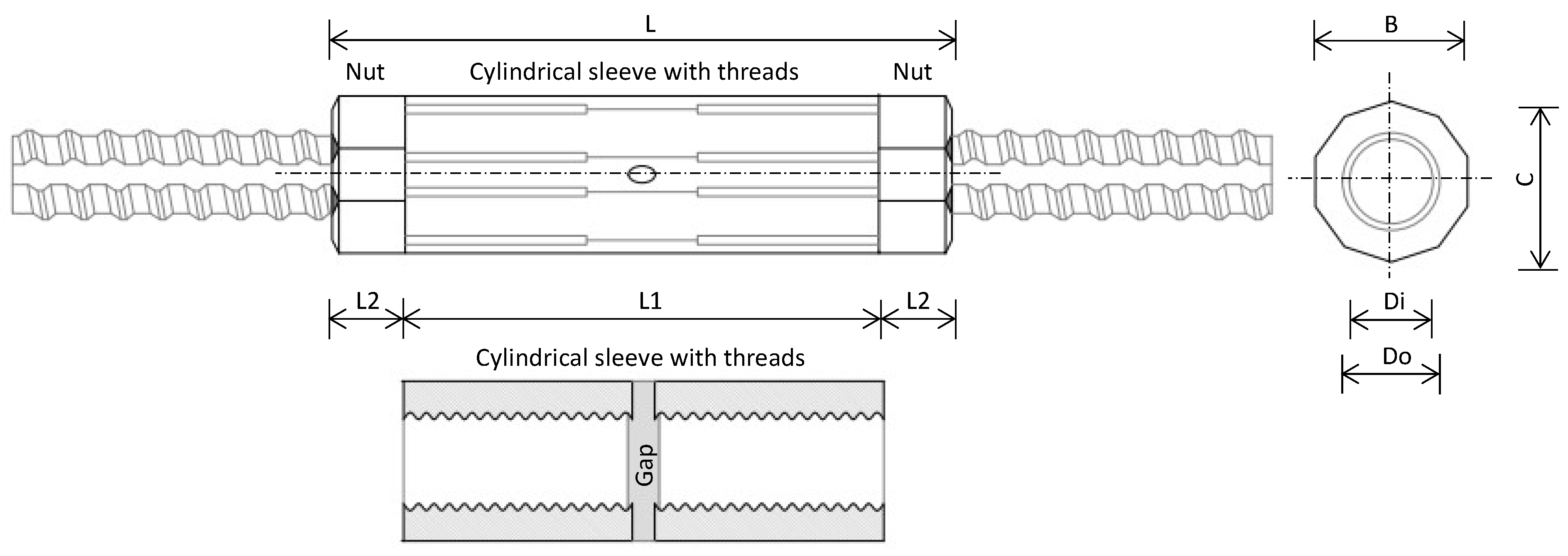
The need for rebar connections in RC structures arises from several practical constraints, including the limited length of supplied rebar, variations in rebar diameter, and transportation-related challenges [16]. In general, three methods are commonly used in rebar work: conventional lap splices, welded splices, and mechanical couplers. Figure 1 illustrates these standard connection methods.
Lap splices remain widely used in construction due to their simplicity and cost-effectiveness in connecting reinforcement bars. However, they introduce inherent drawbacks such as high material usage and waste, rebar congestion, and potential structural integrity issues [8]. Additionally, some building codes, such as the ACI 318, prohibit the use of lap splices for rebar diameters exceeding 36 mm [8]. As an alternative, welded splices reduce rebar usage but require specialized equipment and skilled labor. They are also susceptible to cracking if not executed properly [8]. Mechanical couplers have emerged as a viable alternative, offering a stronger mechanical connection that eliminates the need for overlapping bars [9], thereby significantly reducing rebar demand. Couplers also enable faster installation and improved productivity with comparable labor requirements. Studies [17,18] reported that each coupler required approximately 0.84 min to install, whereas a lap splice required 2–3 min to install. The slower installation time is attributed to the need for three to four wire bindings in each 0.5 m to ensure a secure splicing [11,12,13,14,15,16,17,18]. Despite these benefits, when they are not deployed with well-coordinated planning, the coupler applications may introduce unnecessary cost and installation complexity, further burdening engineers. Couplers come in various types, each with specific characteristics and application requirements. Selecting an appropriate type depends on the project requirements and rebar compatibility as well as applicable local regulations [9].

2.2. BIM for Rebar Work and Digital Integration

Effective intelligent rebar optimization requires more than advanced algorithms; it demands a fully integrated digital workflow. BIM and AI facilitate this integration by aligning design intent with constructability and material efficiency.
BIM has been introduced to facilitate effective early stakeholders’ coordination and collaboration, as promoted by the integrated project delivery (IPD) method, to overcome the drawbacks of the traditional DBB project delivery method [10]. Through a shared digital environment, BIM enables real-time updates, centralized project data management (data retention and retrieval), and seamless collaboration among project participants [10], thus improving accuracy and informed decision-making in construction planning. Several studies [10,19,20,21,22] have applied BIM in rebar-related tasks, particularly to reduce cutting waste. These studies primarily rely on extracting data from structural BIM models as input for optimization algorithms, demonstrating BIM’s potential in streamlining rebar planning workflows [11].
In parallel, several BIM-based rebar layout optimization studies have integrated AI techniques [23,24,25,26,27,28,29]. Mangal and Cheng [23] introduced a BIM-genetic algorithm framework for RC frames, while [24,25] employed artificial potential fields and decomposed PSO for automated layout generation. Other notable contributions include BIM-integrated programming for modeling tools [26], evolutionary algorithms for detailing [27], and rebar plugins [28]. However, many fall short of achieving fully optimized layouts as rebar optimization is absent from those frameworks. More recent studies [10,29] leverage Dynamo with special-length rebar optimization, offering greater accessibility and usability through visual programming without requiring advanced programming skills. However, despite significant progress in BIM- and AI-assisted rebar optimization, existing approaches often overlook the potential of integrating special-length rebars with intelligent, adaptive cutting strategies, leaving a critical gap in achieving truly efficient and flexible solutions.

2.3. AI and Metaheuristic Algorithms for Rebar Optimization

Civil engineering is a broad discipline that spans structural, geotechnical, infrastructure, transportation, water resources, and construction management fields, all aimed at creating a safe and livable built environment [30]. Concurrently, AI has gained significant momentum in civil and construction engineering due to its capabilities in automation, optimization, decision support, natural language processing, machine learning, and continuous improvement [11]. Within this context, optimization plays a crucial role as the process of identifying the best possible solutions under given constraints to fulfill both technological and managerial objectives [30]. Among AI’s various approaches, nature-inspired metaheuristic algorithms have proven particularly effective in addressing the complex and nonlinear optimization problems frequently encountered in civil engineering [30]. One such challenge is the rebar cutting stock problem, which seeks to determine the most efficient rebar combinations and cutting patterns to minimize material waste, a task where traditional trial-and-error and accurate optimization techniques like linear or integer programming are often infeasible [30,31]. In contrast, metaheuristic algorithms are designed to intelligently explore vast solution spaces and generate near-optimal solutions within the given constraints and a reasonable computational time [32]. These algorithms are typically categorized as evolutionary, swarm intelligence, physics-based, human-inspired, or hybrid-based algorithms [33]. Representative examples include genetic algorithm (GA), particle swarm optimization (PSO), simulated annealing (SA), teaching–learning-based optimization (TLBO), and hybrid genetic algorithms, respectively [33].
Several studies have applied such algorithms to solve rebar cutting stock problems. A summary of these metaheuristic algorithm-based solutions is presented in Table 1 below.
As summarized in Table 1, various metaheuristic algorithms have been proposed and employed to address the rebar cutting stock problem. The SOS has been utilized to develop bi-objective cutting plans aimed at minimizing rebar waste while ensuring pattern feasibility [12]. This study found that SOS outperformed PSO in generating more efficient patterns. The fuzzy GA enhanced cutting pattern optimization by integrating fuzzy logic, which improved the quality of the initial population prior to GA optimization [13]. The greedy adaptive PSO (GAPSO) refined rebar cutting schemes [14] by incorporating a greedy approach to construct better initial solutions and an adaptive mechanism to dynamically adjust PSO parameters for better convergence. Wang et al. [15] further advanced the methodology by combining column generation, PSO, and best-fit decreasing heuristics into a hybrid framework. In this approach, column generation generated a pool of valid cutting patterns, PSO was employed for optimization, and the best-fit decreasing algorithm was used to combine a small number of remaining uncut segments.
Despite such advancements, these methods predominantly rely on predefined standard stock rebar lengths (e.g., 9, 10, 11, 12 m) to derive cutting solutions, which limit their ability to minimize waste effectively and expose an existing gap in optimization effectiveness. To overcome this limitation, a recent study introduced a customized pruning-based whale optimization algorithm (WOA), a swarm intelligence-based algorithm tailored to rebar cutting stock problems [11]. This custom WOA integrates a special-length rebar priority concept [34]. This novel framework enables simultaneous identification of the optimal purchasable rebar lengths and corresponding cutting patterns within a specified range to minimize waste, allowing for 0.1 m increments as opposed to standard 1 m increments. A pruning method was employed to eliminate infeasible combinations before optimization. This flexibility over stock lengths allows for more efficient and effective solutions to the rebar cutting stock optimization problem compared to stock-length-based approaches.
Implementing such advanced optimization algorithms necessitates robust programming capabilities. Such capabilities enable the automation of complex tasks, enhance computational efficiency, and minimize human error compared to manual methods [35]. These algorithms are typically implemented in programming languages such as C#, C++, or Python, which support accurate analysis, advanced visualization, and rigorous quality control [35]. Among these, Python stands out for its accessibility, extensive libraries, and strong community support, making it a preferred option in both academic research and industry applications [35].
Large language models (LLMs), such as ChatGPT GPT4-o developed by OpenAI, have demonstrated notable capabilities in generating Python code, providing contextual responses, and follow-up prompts [36], thereby accelerating research and development efforts [35]. Several studies [35,37,38,39,40] have evaluated its performance across various domains, highlighting its strengths while also pointing out limitations, particularly in terms of algorithm accuracy and debugging capabilities. While concerns regarding these limitations persist, there is a consensus that, when guided by clear user prompts, ChatGPT can effectively support research and development efforts, demonstrating benefits that outweigh its limitations [11]. While existing studies lay the groundwork for AI-assisted rebar optimization, the unique reinforcement requirements of diaphragm walls warrant a more tailored approach. The subsequent section outlines these key structural and constructability features that shape the proposed framework.

3. Overview of Diaphragm Walls: Design, Construction, and Reinforcement Characteristics

3.1. Design and Construction of Diaphragm Walls

Underground construction plays an essential role in enhancing the quality of life in cities by optimizing the use of limited and densely urban areas [4]. Among various underground RC systems, diaphragm walls are particularly significant. These vertical or slightly inclined RC structures are commonly employed in underground construction, foundation systems, and retaining walls to provide lateral support against soil, water pressure, and other applied lateral loads [8]. Owing to their high stiffness, structural integrity, and excellent seepage resistance, diaphragm walls are extensively used in constructing urban subway stations [3,5]. Furthermore, their low vibration and noise emissions make them especially suitable for projects near existing buildings [5,41], contributing to their popularity in dense urban environments.
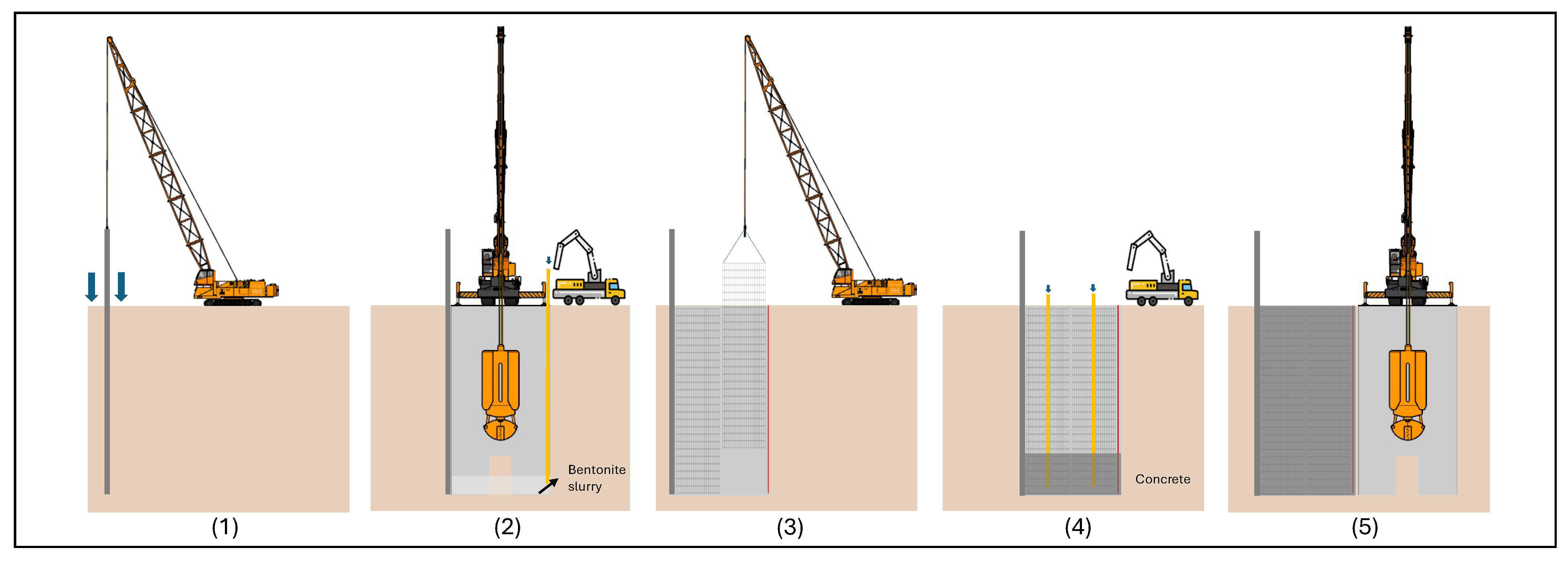
A diaphragm wall system generally comprises multiple wall panels, each ranging from 3 to 7 m in length and 0.6 to 1.8 m in thickness, depending on structural requirements. Construction starts with primary panels, followed by secondary panels, which are joined using water-stop joints, selected based on contractor preference and experience. As commonly described in the literature [3,5,8], the general construction sequence is presented in the step-by-step outline and illustrated in Figure 2 below.
  • Guide wall construction: Shallow guide walls define alignment and support trench excavation.
  • Deep trench excavation: Trenches are excavated and stabilized using bentonite slurry to prevent collapse.
  • Rebar cage installation: Prefabricated rebar cages are lowered into the slurry-filled trench.
  • In-situ concrete placement: Concrete is poured and cast using a tremie pipe from the bottom upward.
  • Soil excavation around the panel: Hardened panels are exposed by excavating the surrounding soil to prepare for subsequent construction stages (station).
  • Wall monitoring and additional reinforcement: Stability and deformation are monitored, and reinforcement is added as needed.
Ensuring diaphragm wall integrity requires effective construction management, including proper sequencing, high-quality materials, and precise panel installation to prevent rebar exposure [3], which could compromise structural performance. Accordingly, the configuration and placement of the rebar within the wall is critical and must be thoroughly understood, carefully planned, and executed.

3.2. Structural Requirements, Reinforcement, and Connection Characteristics

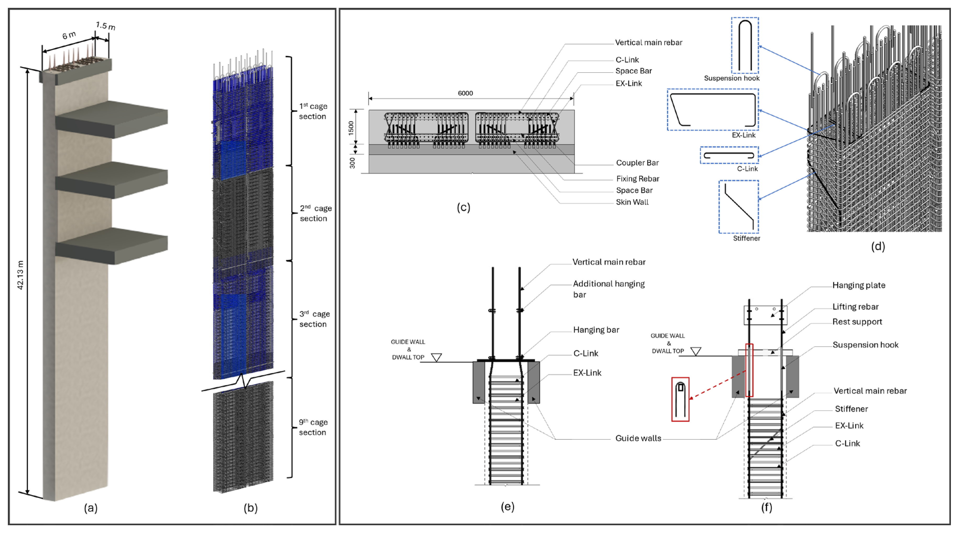
Diaphragm walls require substantial steel reinforcement to withstand lateral soil and water pressure, seismic forces, vertical loads, and additional horizontal loads from adjacent structures and excavation activities [8,41]. This reinforcement is prefabricated into rebar cages, typically divided into multiple sections based on the wall’s depth and inserted sequentially into the excavated trench [8]. Each panel is generally mandated by design regulations to incorporate two layers of rebar cages [41], which are anchored at each floor slab using starter bars to ensure structural continuity. The cage is typically composed of main vertical rebars, which resist axial and flexural (bending) loads, horizontal ties which help distribute loads uniformly, and shear links (or ties) which provide resistance to lateral shear forces. Additional components, such as spacers, stiffeners, fixing bars, hanging bars, suspension hooks, and lifting rebars, maintain cage stability and ease installation. Horizontal elements like EX-links and C-links maintain the position of vertical rebars, functioning similarly to column hoops. Figure 3 illustrates these rebar arrangements. However, sequential rebar cage installation in deep trenches is often constrained by equipment limitations and trench geometry. The narrow working space can hinder secure connections, particularly when using conventional lap splices that require long overlap lengths and significant manual labor for binding. This limitation highlights the need for intelligent connection strategies. Mechanical couplers offer a space-efficient and labor-saving alternative, allowing direct cage-to-cage connections that are especially advantageous in confined conditions, such as those in diaphragm wall construction. However, in some cases, conventional lap splices may still be preferred as they offer simplicity and cost-effectiveness. Understanding these reinforcement and connection challenges sets the foundation for the intelligent optimization framework discussed in subsequent sections.

4. Development of Intelligent Rebar Optimization Framework

Traditional DBB-based practices often result in fragmented rebar planning and significant material waste due to reliance on stock-length bars and conventional lap splices [10,11]. In contrast, integrated approaches enabled by BIM and IPD promote resource-efficient planning and system-wide optimization. Diaphragm walls, due to their uniform reinforcement arrangements, offer a strategic opportunity for system-wide optimization, thereby significantly reducing cutting waste [42]. Several studies have explored rebar optimization through the use of special-length rebar, splice position adjustments, and mechanical couplers [8,42]. Studies show that splice repositioning can maintain structural performance even beyond designated zones [43], while mechanical couplers more effectively reduce rebar usage and waste [8]. However, these methods largely remain manual and inefficient, highlighting the need for a more intelligent and automated optimization framework.
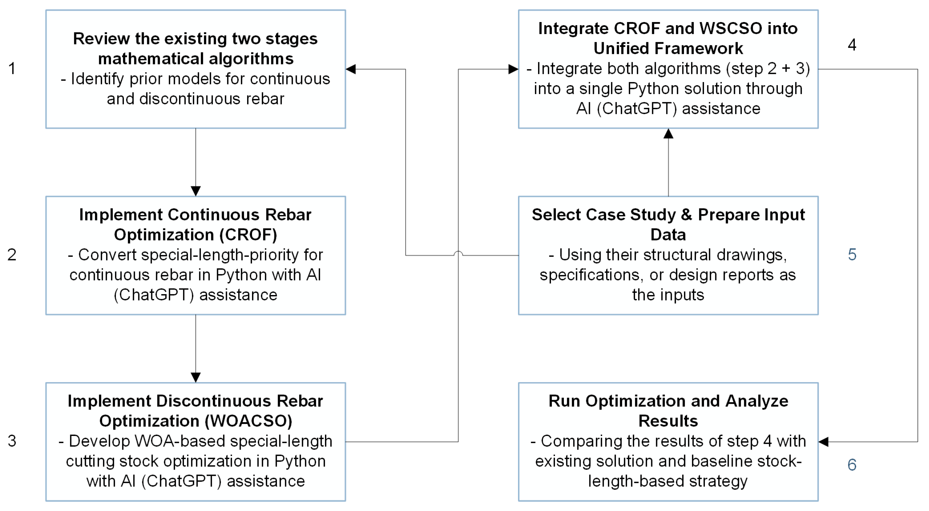
To address this gap, an earlier study [11] proposed a two-stage integrated framework, continuous and discontinuous rebar optimization, implemented in Python for various superstructure elements, such as columns, beams, slabs, and walls. It combined a special-length priority method with a whale optimization algorithm (WOA)-based cutting stock optimization model and demonstrated high efficiency. Building upon this foundation, the present study introduces a specialized optimization framework tailored for diaphragm wall systems. The development process follows a structured set of sequential steps, as illustrated in Figure 4.
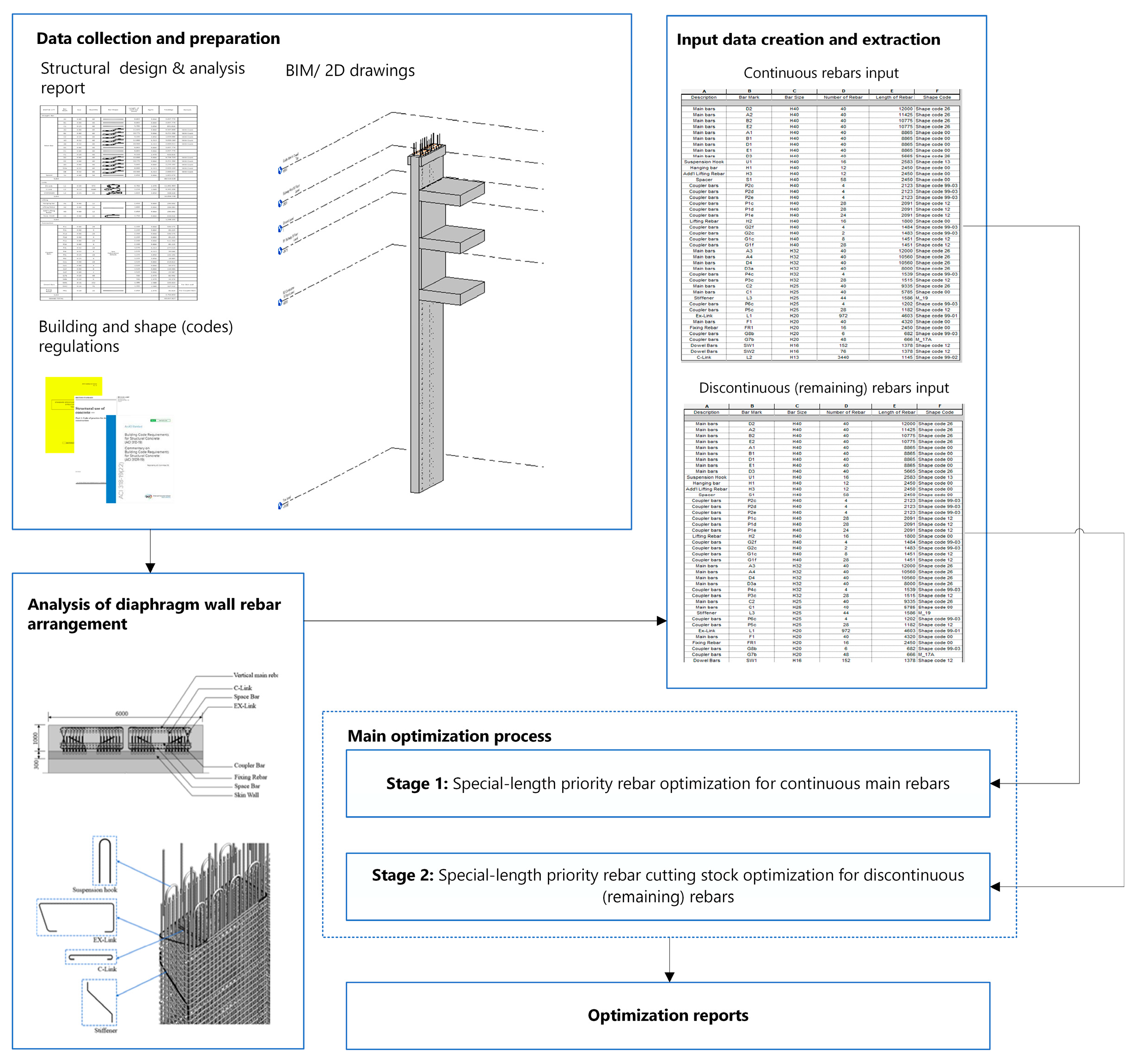
Step 1 compiled and reviewed the existing mathematical two-stage special-length priority models (continuous and discontinuous rebar) for diaphragm walls, as established in previous studies and illustrated in Figure 5. Step 2 converted the continuous-reinforcement algorithms to Python; ChatGPT was used under supervision to accelerate and validate the code through task-specific prompts. Step 3 similarly refined the cutting stock optimization using Python (Spyder IDE), incorporating a metaheuristic algorithm. Step 4 merged all scripts into unified, single Python solutions. Step 5 applied the algorithms to case studies derived from 2D drawings, design reports, or BIM models in Autodesk Revit, demonstrating BIM-based data coordination and model integration. Finally, Step 6 benchmarked the new results against the existing solution for validation, including the prior model (Step 1) and the stock-length-based strategy. The complete Python code is provided in Appendix A.

4.1. Existing Two-Stage Optimization Framework

As shown in Figure 4, the first stage consists of several steps to identify the special-length rebar that minimizes the waste. A previous study [8] has established a set of mathematical equations to identify the special-length rebar utilizing a mechanical coupler connection. As previously mentioned, the strategic placement of the coupler has demonstrated a more efficient material usage and rebar waste compared to the conventional lap splices, including the one that utilizes the flexible lap splice position approach.
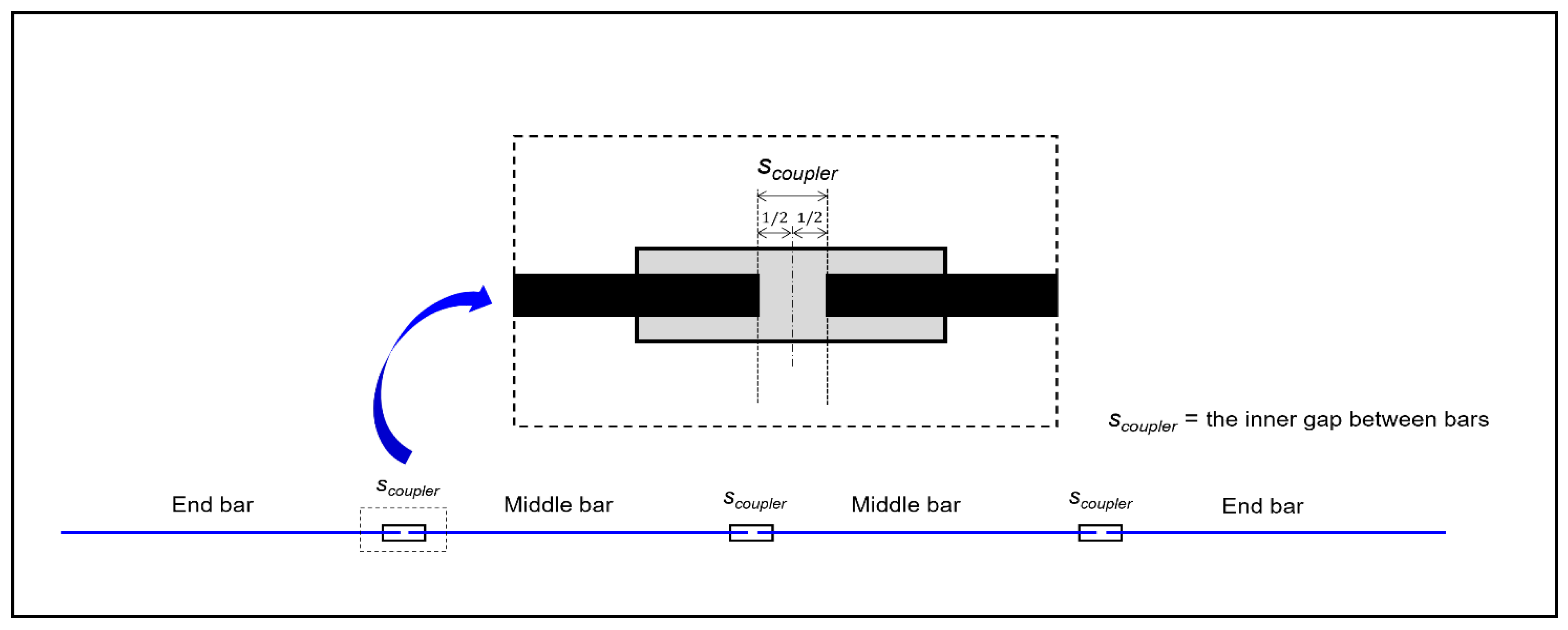
The key distinction in this approach is the integration of mechanical couplers into the calculation process, where the coupler’s inner gap influences the determination of special lengths, as illustrated in Figure 6. The coupler’s gap also affects how bars are classified as end or middle bars. In addition to eliminating lap splicing, couplers offer flexible placement along the structure [11].
Nevertheless, the established algorithm’s [8] process and details are outlined below.
  • Data Preparation: Retrieve all relevant input data, including basic rebar information from the structural analysis report (e.g., location, size, number, spacing), detailing requirements from applicable building codes (e.g., coupler inner gap, anchorage length, concrete cover), and geometric information of standard diaphragm walls (e.g., dimensions and location) from BIM models or 2D drawings.
  • Using the input data, calculate the total continuous-reinforcement length required for the main reinforcement of a standard diaphragm wall, as described by Equation (1). The total reinforcement length ( L t o t a l ) is determined by summing the lengths of rebars in each layer sharing the same diameter. In diaphragm wall construction, rebar cages typically consist of multiple layers with varying diameters, where smaller diameter rebars are generally used in deeper sections of the wall.
    L t o t a l = i = 1 r L r e b a r _ i
    where L r e b a r _ i is the length of rebar i , and   r is the upper limit of the summation, which is the total number of rebars considered in the total length calculation.
  • The special length ( l s p e c i a l _ P O ) that can be purchased is calculated by applying the total length calculated in Equation (1) following these equations.
    (1)
    Calculate the number of special lengths using Equation (2).
    n r e b a r = L t o t a l L m a x
    where L m a x denotes the maximum rebar length that can be purchased.
    (2)
    Special bar lengths ( l c a l c ) are determined by incorporating the coupler’s inner installation gap, which influences both bar classification and length adjustment. As shown in Figure 6, a threaded coupler provides clearance for thread misalignment and grouting; half of this gap is deducted from an end bar, whereas the full gap is deducted from a middle bar. The resulting special lengths are calculated with Equation (3) for end bars and Equation (4) for middle bars.
    L c a l c e n d = r o u n d u p   L t o t a l n r e b a r s c o u p l e r 2
    L c a l c m i d = r o u n d u p   L t o t a l n r e b a r s c o u p l e r
    where, s c o u p l e r denotes the inner gap of the coupler.
    (3)
    The purchasable special length ( l s p e c i a l _ P O ) is calculated using Equation (5), selecting the larger of the two values generated from the previous step, represented by Equations (3) and (4).
    l s p e c i a l _ P O = L t o t a l n r e b a r × 10 / 10
As previously discussed in Section 3, the rebar arrangement in a diaphragm wall consists of both continuous main bars and shorter, discontinuous segments, referred to in this study as remaining bars. The additional rebars, such as ties, spacers, stiffeners, fixing bars, and hanging bars, are generally considered remaining rebars. In some cases, discontinuous pieces may also occur within the main reinforcement. Rebars are first grouped by diameter and length, then processed using a special-length cutting stock optimization algorithm [34] to determine the optimal purchasable lengths and corresponding cutting patterns, as illustrated in Figure 5.
The process of fulfilling project-specific rebar requirements inevitably results in cutting and trimming losses when using stock-length rebars [44]. Regardless of variations in rebar length, diameter, or production methods, all rebars must be cut to specified lengths in accordance with predefined rules to meet the structural specification [14]. In this study, it is assumed that purchasable special lengths l s p e c i a l _ P O are available in 0.1 m increments and in unlimited supply [45]. These must be cut into various length l j   l 1 ,   l 2 , l 3 , ,   l n , with corresponding demands d j   d 1 ,   d 2 , d 3 ,   ,   d n [45]. The lengths l j are grouped into cutting patterns, each having a total cutting length l c o m b i , with the goal of minimizing cutting waste (objective function, Equation (6)). The decision variable n i denotes the number of l s p e c i a l _ P O assigned to pattern i . Constraints in Equations (7) and (8) ensure demand fulfillment and compliance with the allowable special-length range.
M i n i m i z e   f ( X i ) = i = 1 N l s p e c i a l _ P O i × n i l c o m b i × n i l s p e c i a l _ P O i × n i
S u b j e c t   t o   l c o m b i l s p e c i a l _ P O i ,   l c o m b i = j = 1 n l j × d j
l m i n   l s p e c i a l _ P O i l m a x

4.2. 1st Stage: Continuous Rebar Optimization Framework (CROF) in Python

The previous section outlined the sequential steps for optimizing the continuous reinforcements of a diaphragm wall. These steps were subsequently converted and implemented in Python, with development supported by ChatGPT to establish an efficient framework named the Continuous Rebar Optimization Framework (CROF). To facilitate execution, standardized input sheets must first be designed. A spreadsheet file containing two standardized sheets served as the input source.
The first sheet outlines rebar specifications and building parameters in accordance with regulatory requirements. These include bar diameter, concrete strength, rebar steel grade, concrete cover, inner gap of coupler, and rebar unit weight. The second sheet presents structural reinforcement data obtained from structural design outputs, including rebar length, the number of rebars in a bundle for each rebar group, and other relevant details like total rebar length required per group. This framework has been implemented in Python, and its logic, covering special-length prioritization and coupler allocation, is summarized in Pseudocode A1 (see Appendix A).

4.3. 2nd Stage: WOA-Based Special-Length Rebar Cutting Stock Optimizer (WOACSO) in Python

Metaheuristic optimization algorithms have gained widespread use in engineering due to their simplicity, ease of implementation, independence from gradient information, robustness in avoiding local optima, and applicability across various problem domains [46]. Among these, particle swarm optimization (PSO) and the genetic algorithm (GA) are frequently applied in structural design, with PSO often demonstrating superior performance in identifying optimal solutions [47]. In terms of computational efficiency, the material generation algorithm (MGA) and the whale optimization algorithm (WOA) have shown notable advantages. At the same time, other methods such as harmony search (HS), the firefly algorithm (FA), social network search (SNS), and grey wolf optimization (GWO) exhibit comparable convergence behavior. Nevertheless, algorithm performance remains problem-specific. Studies on energy systems and photovoltaic applications report WOA outperforming PSO in solution quality [45,46,47,48,49], a finding supported by a meta-analysis highlighting WOA’s faster convergence and balanced exploration–exploitation dynamics [50].
Based on these strengths, this study adopts the whale optimization algorithm (WOA) [46], a metaheuristic and AI-based optimization technique, to enhance the established special-length priority cutting stock optimization [13]. WOA is integrated into the framework to improve the efficiency and adaptability of cutting pattern optimization for discontinuous rebar arrangements in diaphragm walls, guided by the objective function and constraints defined in Equations (6)–(8). While the existing algorithm enhances adaptability compared to stock-length-based cutting stock optimization, it still requires an optimized approach to effectively determine cost-efficient rebar lengths and cutting schemes [42,43,44,45]. This metaheuristic integration enables efficient navigation of complex search spaces and yields near-optimal solutions, thereby reducing waste caused by fixed stock-length limitations where conventional methods prove inadequate [11]. The development and refinement of the proposed framework were supported by ChatGPT through guided prompt-based assistance.
The WOA mimics the bubble-net feeding behavior of humpback whales [46]. WOA operates through three behaviors: encircling prey, bubble-net feeding, and searching for prey. During the encircling prey phase, agents move toward the best-found solution. The bubble-net feeding phase uses spiral movements to enhance solution exploitation. Meanwhile, the search for prey behavior balances exploration and exploitation phases, enabling agents to discover new solutions while avoiding local optima and refining the best-known solutions. Key advantages of WOA over other algorithms include (1) an explicit exploration–exploitation control balance achieved by parameter adaptation during iterations, (2) random initial movements that encourage global search followed by progressively refined steps, (3) adaptive responses to neighboring solutions that help avoid local minima and improve solution quality, and (4) algorithmic simplicity, owing to a small parameter set, which reduces computational cost and facilitates implementation, especially accessible even to users with limited programming skills.
WOA employs several key parameters to guide its execution: X*, A, C, l, p, and t. X* represents the best solution found, the candidate with the highest fitness. The parameter a controls the balance between exploration and exploitation, decreasing linearly from 2 to 0 over iterations. A and C influence the movement of search agents, A modularized step size, while C directs agents toward X*. The random value l within [−1, 1] governs spiral movement during exploitation. The probability p determines whether the algorithm performs exploration or exploitation and further guides the selection between encircling and spiral strategies. t denotes the current iteration. The procedural steps of the WOA-based special-length cutting stock optimization (WOACSO) framework are detailed in Pseudocode A2 (see Appendix A) [11].
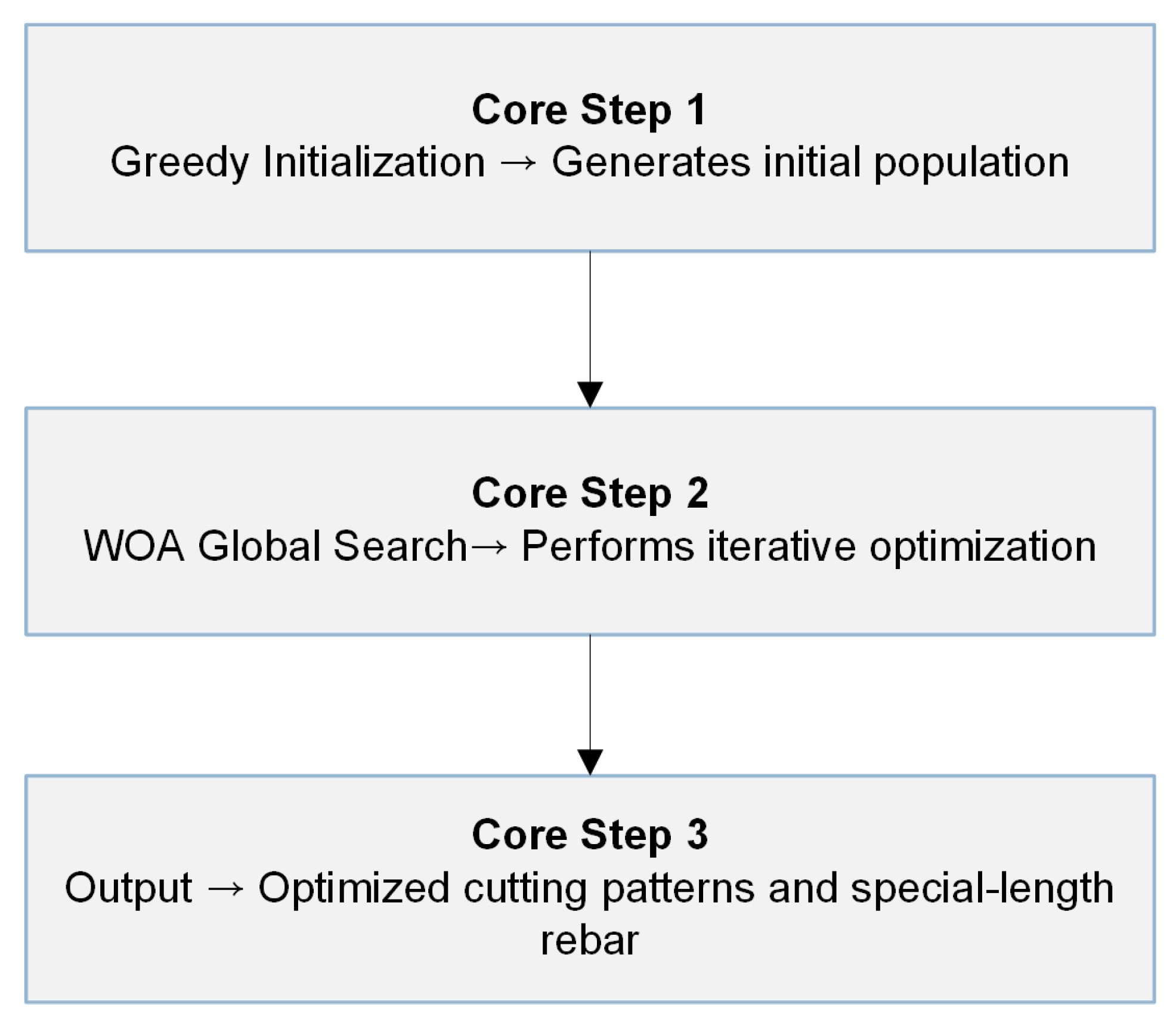
As shown in the pseudocode, the algorithm begins by initializing a population of search agents (whales) and importing the required rebar lengths and quantities from an input spreadsheet. Initially, a combinatorial search function with pruning is used to generate and refine cutting patterns by eliminating inefficient combinations [11]. However, this approach can be relatively slow, particularly when handling large datasets. To enhance computational efficiency and scalability, a greedy search function is introduced. Greedy search is a rapid and efficient method that makes the optimal choice at each step based on a defined metric, without considering the broader solution space [14]. Unlike pruning, which systematically explores and eliminates suboptimal branches, greedy search selects the best immediate option at each step without exhaustively evaluating all possibilities. While this method significantly improves runtime and integrates effectively with the metaheuristic optimization loop, it may not always yield a global or near-optimal solution. Considering the large number of lengths and their corresponding quantities typical of diaphragm wall systems, the greedy search function is adopted despite its potential drawbacks. Each agent’s fitness is evaluated based on total waste, and the best solution is iteratively updated until the maximum number of iterations is reached. The final output, comprising the optimal cutting patterns and special rebar length, is saved to a spreadsheet file for practical use, with the optimal special length returned as the final solution. To clarify the working logic of the integrated optimization strategy, the overall flow of the framework is summarized in Figure 7.
As shown in Figure 7, the optimization process begins with a greedy algorithm that generates a high-quality initial population of cutting patterns. These patterns are then refined using the WOA, which iteratively minimizes cutting waste through global search. Each agent’s fitness is evaluated based on total trim loss, and the best solution is updated throughout the optimization process. Given the strong performance of the WOA-based optimization, additional refinement steps such as backtracking were not adopted. Table A1 in Appendix A compares the conventional greedy-only method, which uses fixed 12 m rebar, with the proposed WOACSO that explores flexible lengths from 6 to 12 m. A small-scale instance confirms WOACSO’s superior performance in reducing cutting waste.

4.4. Integrated Intelligent Rebar Optimization Framework for Diaphragm Wall

The previously developed and refined frameworks were consolidated into a single intelligent optimization framework implemented in Python IDE, with ChatGPT assistance under close supervision through guided prompts. As outlined earlier, the framework distinguishes between continuous and discontinuous reinforcement, forming a sequential, two-stage optimization framework. Stage 1 deals exclusively with continuous reinforcement. Stage 2 then addresses discontinuous reinforcement, i.e., the additional embedded bars previously defined and illustrated in previous sections.
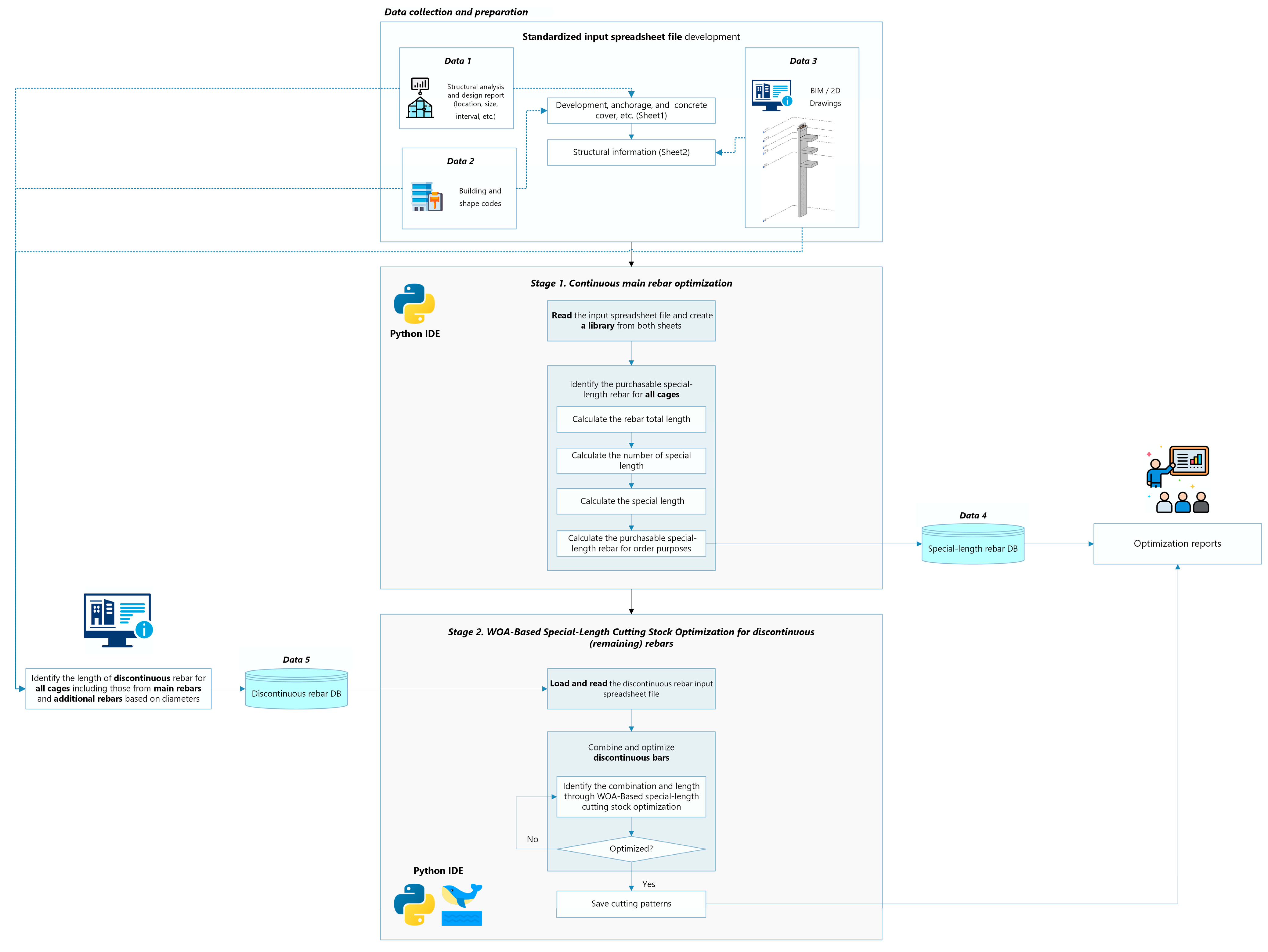
Before the second stage begins, every discontinuous bar is identified and listed in a spreadsheet that records its length ( l j ) and quantity ( d j ) in a sorted manner based on rebar diameter and length order to prevent duplication, therefore ensuring input accuracy. When the optimization framework concludes, two separate spreadsheet files are generated: (i) a summary of special-length bars and their corresponding cutting patterns, and (ii) a summary of the optimized continuous reinforcement. This structured approach ensures a well-integrated, comprehensive, and efficient system. An overview of the intelligent framework is presented in Figure 8. The complete integrated algorithm, including the code and detailed pseudocode, is provided in Appendix A.
As illustrated in Figure 8, the architecture of the proposed intelligent rebar optimization framework comprises two core stages introduced earlier: the Continuous Rebar Optimization Framework (CROF) and the WOA-based special-length cutting stock optimizer (WOACSO). The framework is designed to reflect real-world constructability, particularly those associated with diaphragm wall reinforcement. Rebar inputs are categorized into continuous and discontinuous types. CROF processes continuous bars by assigning special-length rebars and couplers, while WOACSO applies the Whale optimization algorithm to generate optimal cutting patterns for discontinuous bars, minimizing waste through efficient special-length allocation.
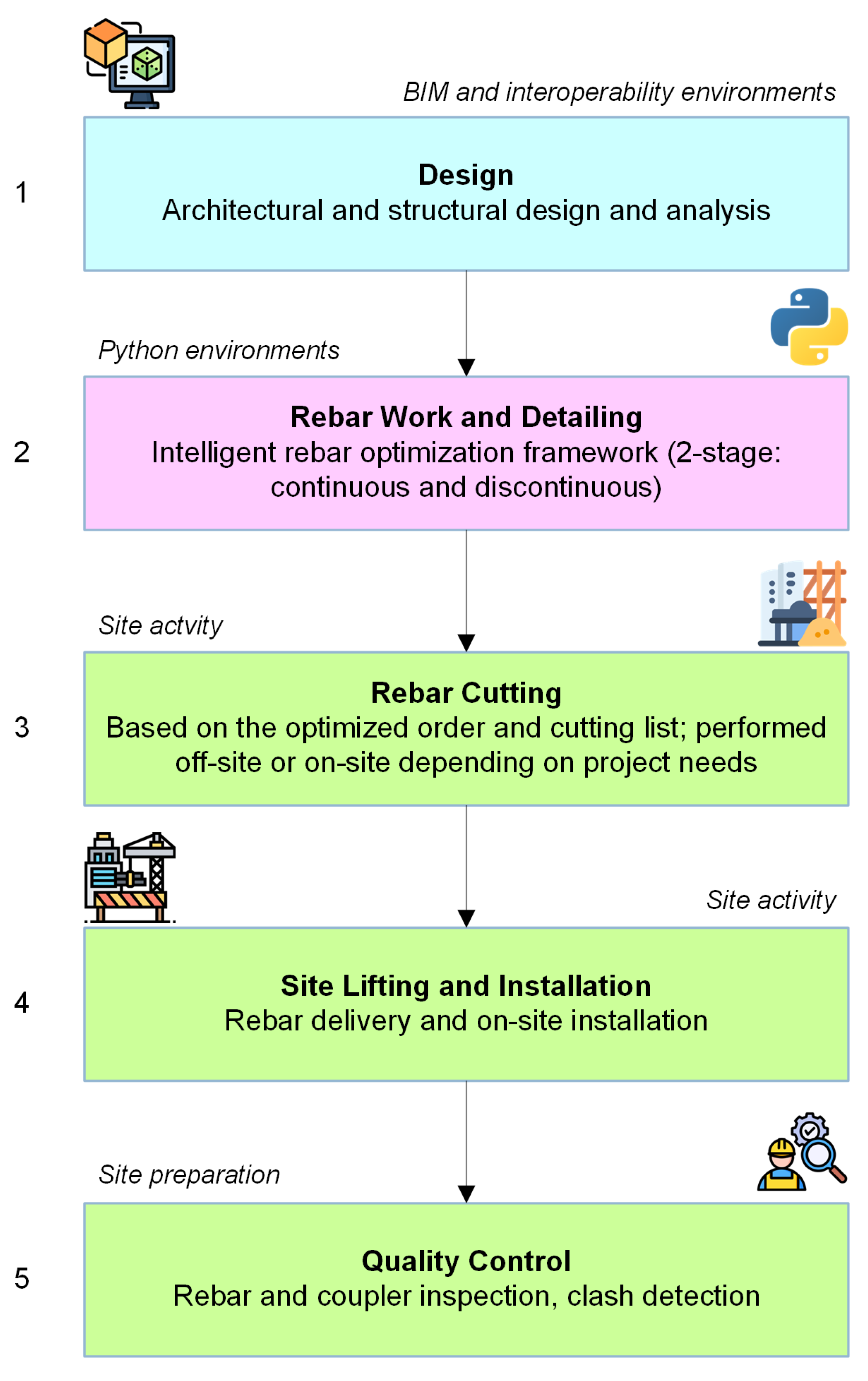
From a broader perspective, the end-to-end implementation of the proposed framework is illustrated in Figure 9, showing how the process progresses from design to on-site execution. It begins with digital inputs derived from structural analysis or BIM models, followed by rebar detailing through the proposed optimization framework. The resulting cutting lists guide the rebar fabrication process, which may occur off-site or on-site before delivery, lifting, and installation. The final stage involves site-level quality control, including rebar and coupler inspection as well as clash detection. To enhance clarity, the workflow is color-coded: blue represents BIM input, purple indicates optimization stages, and green denotes site-level activities.

5. Case Application and Validation

5.1. Case Study Selection and Preliminary Settings

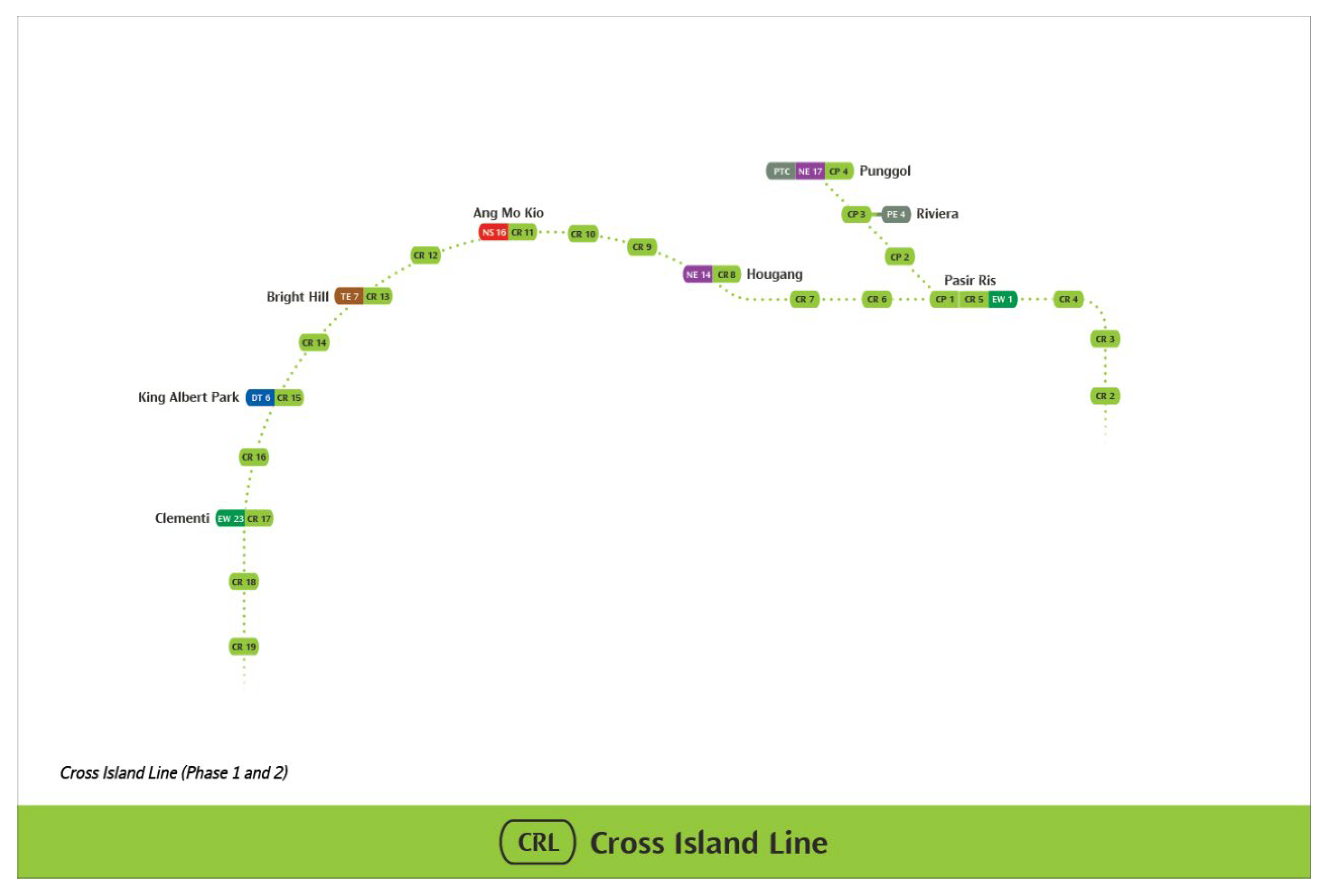
A diaphragm wall from the Cross Island Line CR108 MRT Project in Singapore was selected as the case study. This MRT line, the longest fully underground transit corridor in Singapore at over 50 km, serves both existing and future developments across the eastern, western, and northeastern regions, connecting major urban hubs and areas [51]. Upon completion, it will include 22 stations, eight of which are interchange stations. The scale and strategic significance of the project amplify the relevance and potential impact of this study when applied to diaphragm wall construction within intelligent and sustainable rebar planning frameworks.
As shown in Figure 10, the CR108 diaphragm wall project is located along the Cross Island Line, which spans across key urban and interchange zones in Singapore. Moreover, Singapore’s leadership in urban transit innovation and digital construction technologies make it a strategic setting to demonstrate the utility of intelligent rebar planning solutions. The insights gained are highly transferable to other similar urban areas worldwide.
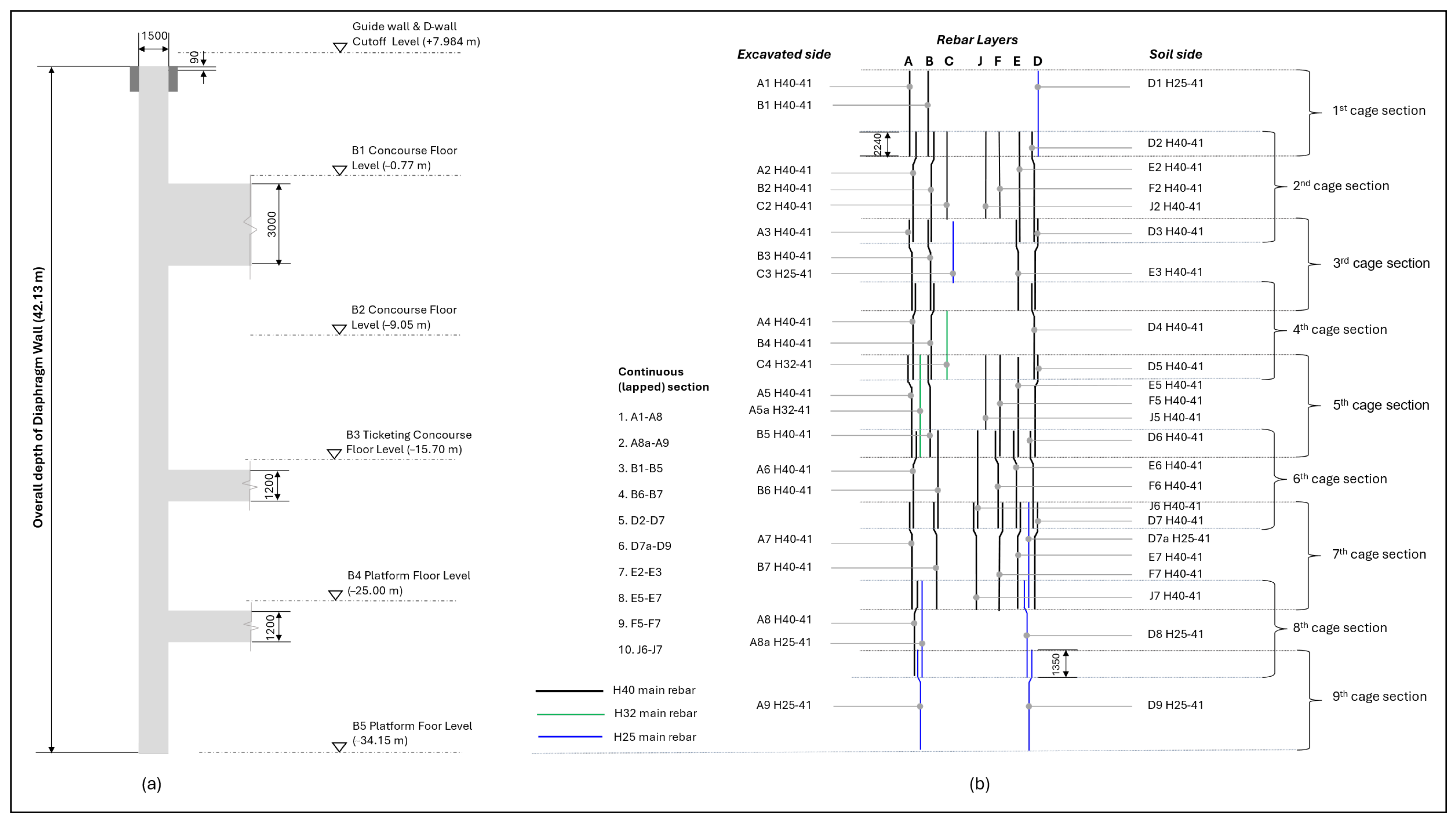
The selected wall panel spans 6 m in length, 1.5 m in thickness, and extends to a depth of 42.13 m. It connects five floors of the subway interchange station and is reinforced with 24 MPa concrete and 500 MPa rebar, with bar diameters ranging from H25 to H40. The reinforcement is organized into two cages, each subdivided into nine segments. Threaded rebars and rib-threaded couplers (RTC) were utilized due to their mechanical reliability as an alternative to lap splices. The RTC, a cylindrical sleeve with threaded ends, securely connects rebars via nut fastening and is reinforced with grouting material to enhance the rebar–concrete bonding (see Appendix B) [52]. To ensure compatibility, threaded rebars from the same manufacturer, Tokyo Tekko Co., Ltd. (Tokyo, Japan) [53], are used. Appendix B provides the coupler specifications and illustrates the typical thread gap. Typical values for the gap are 20 mm for D16–D29 and 30 mm for sizes above D32. Rebar optimization was carried out based on a previously developed framework. The dimensions and reinforcement cage configuration of the selected panel are illustrated in Figure 11. The original rebar list is provided in Appendix B.
The developed framework was implemented in the selected case study, referred to as Step 5. Input data were obtained either directly from structural analysis results, 2D design drawings, specifications, and relevant detailing standards, or extracted from digital structural models created in Autodesk Revit software. This process aligns with a BIM-based workflow that promotes data consistency and traceability. ChatGPT GPT 4-o, an AI-based tool, was employed to assist the conversion and enhancement of manual algorithms into Python code through supervised, task-specific prompts, thereby accelerating development while maintaining accuracy.
The parameters assigned for the WOA-based special-length priority cutting stock optimization are summarized in Table 2. The algorithm was designed to minimize the objective function defined in Equations (6)–(8). The integrated optimization framework was developed in Python 3.12.7 and executed using the Spyder IDE (Anaconda distribution) on a Windows 11 system equipped with an Intel Core i7-12700F processor, 32 GB of RAM, and an NVIDIA GeForce RTX 3060 Ti GPU (8 GB VRAM).

5.2. Intelligent Rebar Optimization Framework Application

As previously noted, a standardized input sheet must be prepared prior to executing the optimization. This sheet includes rebar specifications and layer-wise rebar details. Based on the rebar grouping by layer and diameter shown in Figure 10, examples of standardized inputs are presented in Table 3 and Table 4. The remaining discontinuous bars required for the diaphragm wall are listed in Appendix B and were used to generate cutting combinations. Using these inputs, the proposed two-stage optimization framework was implemented as defined in the previous section.

5.3. Verification, Validation, and Result Analysis

To ensure both the technical correctness and practical effectiveness of the proposed intelligent optimization framework, this section presents its verification and validation.

5.3.1. Verification

Verification was conducted by implementing the developed intelligent Python-based framework’s modules using real-world input data from a diaphragm wall project, as described in Section 5.2. The modules, covering both continuous and discontinuous optimization stages, were assessed for logical accuracy, computational consistency, and stability. Intermediate outputs such as the assigned special-length bars, coupler allocation, and cutting patterns were reviewed to confirm that the implemented algorithm functions as intended. The results of the CROF are summarized in Table 5, while Table 6 presents the outcomes of the WOACSO applied to the discontinuous remaining bars, including the identified special lengths and associated waste.
The optimization of the diaphragm wall’s continuous reinforcement by layer, as summarized in Table 5, yielded multiple solutions with special-length rebars ranging from 7.0 to 11.9 m. This required a total procurement of 89.212 tons of rebar and 615 mechanical couplers (533 for H40 and 82 for H25 bars). For the discontinuous bars, the optimal special-length range was identified between 10.3 and 11.7 m, as detailed in Table 6, resulting in a total of 84.320 tons. Overall, in this diaphragm wall, 173.532 tons of rebar were procured, of which 170.783 tons were utilized, resulting in 2.749 tons of waste.

5.3.2. Validation and Result Analysis

Validation was conducted through comparative analysis with a widely used commercial tool, CuttingPro, which implements a stock-length-based optimization strategy using standard 12 m rebar. The same case study was evaluated using both approaches in parallel as part of Step 6 of the framework, as illustrated in Figure 4. In addition to relying on stock-length rebar, the conventional method employed traditional lap splicing techniques. The evaluation focused on these key indicators, including total rebar usage, cutting waste generation, computational time, and the associated environmental and cost impacts, to assess the framework’s overall effectiveness.
  • Rebar Usage, Waste, and Computational Time
A stock 12 m rebar is used for comparison purposes. The identical case study was applied with the conventional stock-length based optimization using CuttingPro v5.17.2.0 software to obtain the solutions. Table 7 summarizes the resulting rebar usage and waste, while Figure 12 illustrates a comparative analysis between the outcomes of the conventional approach and those of the proposed intelligent framework.
As shown in Figure 12, the stock-length-based optimization required 198.443 tons of rebar, whereas the intelligent rebar optimization required only 170.783 tons, resulting in a 13.94% reduction. Regarding total rebar usage, the stock-length-based optimization used 216.262 tons, while the proposed intelligent framework required 173.532 tons, achieving a 19.76% reduction. In terms of waste generation, the stock-length-based optimization produced 17.819 tons of waste, compared to only 2.749 tons under the intelligent approach, an 84.57% reduction. These findings demonstrate the proposed framework’s effectiveness in significantly improving rebar efficiency and minimizing material waste.
Beyond material performance, computational efficiency also plays a key role in evaluating optimization frameworks. In this context, computational time reflects the efficiency of the developed algorithms in identifying optimal solutions, where longer processing times indicate slower convergence and higher resource demands [11]. The stock-length-based optimization approach required approximately 30 min to generate feasible solutions. In contrast, the proposed intelligent framework converged to feasible solutions in under 20 s. This substantial reduction highlights the computational efficiency of the proposed approach and reinforces its effectiveness in minimizing rebar usage and waste.
b.
Associated Carbon Emissions and Costs
As previously discussed, the construction industry is responsible for approximately 39% of global energy consumption, 28% from operational activities and 11% from the embodied carbon of building materials. In this context, rebar contributes significantly to carbon emissions, producing more carbon emission and greenhouse gases (GHG) during manufacturing than concrete [8]. According to a separate study [54], rebar production emits approximately 3.505 tons of CO2-equivalent per ton of steel, whereas the production of 1 m3 of 24 MPa concrete emits 140.43 kg CO2-eq, or equal to 58.51 kg CO2-eq per ton. These findings highlight the importance of reducing rebar usage and waste in the construction sector. Additionally, the carbon emissions associated with mechanical couplers are estimated at 23.98 kg CO2-eq per H40 coupler and 8.6 kg CO2-eq per H25 coupler [8]. Therefore, any reduction in rebar or coupler usage directly translates into lower embodied carbon. To estimate carbon emissions in the stock-length-based optimization scenario, the total rebar usage (i.e., the total purchased quantity, as presented in the previous section) is multiplied by the unit carbon emission factor for rebar. For the proposed framework, emissions are similarly calculated by multiplying the total rebar usage by the corresponding rebar emission factor. Additionally, emissions from couplers are accounted for by multiplying the number of couplers used, categorized by diameter, by the emission factor specific to each coupler type. The total embodied carbon is then obtained by summing the contributions from both rebar and couplers. A comparison of the carbon emissions generated by each optimization approach is presented in Table 8.
As shown in Table 8, the carbon emissions generated by the stock-length-based optimization approach amounted to 758 tons of CO2-eq. In contrast, the proposed intelligent optimization reduced emissions by 136 tons CO2-eq, demonstrating improved sustainability performance. This reduction highlights the potential of intelligent rebar optimization to mitigate the environmental impact associated with rebar usage. The findings align with smart city development goals that prioritize environmentally responsible construction practices.
To further mitigate environmental impact, many countries have implemented carbon tax policies, imposing a fee per ton of carbon emissions to incentivize greener technologies. In Singapore, the carbon tax is currently set by the government at SGD 25 per ton of CO2, with an increase to SGD 45 scheduled for 2026 [55,56]. This implies that failure to adopt smart and sustainable practices could lead to substantial financial penalties. In addition, improper disposal of rebar waste contributes to greenhouse gas (GHG) emissions, prompting other jurisdictions to adopt waste reduction measures. For instance, Hong Kong introduced a Construction Waste Disposal Charging (CWDC) policy [57], where disposal fees vary based on the designated waste destination. Rebar waste sent to sorting facilities for recycling incurs HKD 175 per ton, while disposal at public fill reception facilities costs HKD 71 per ton, equivalent to approximately SGD 28.23 and SGD 11.45, respectively, based on prevailing exchange rates [58]. This study assumes that rebar waste is directed at recycling facilities.
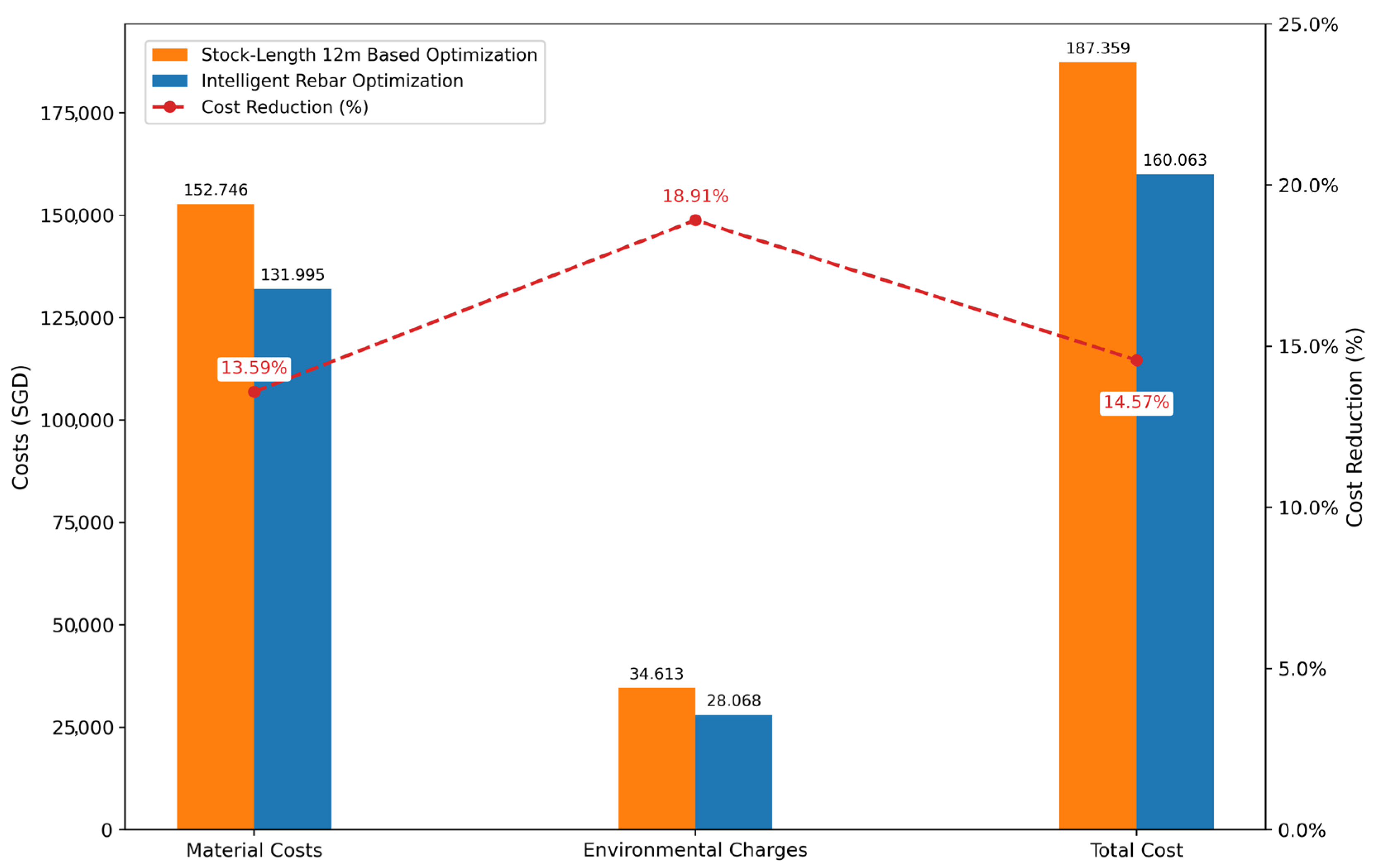
The total cost in each framework comprises both material and environmental components. Material costs include rebar expenses in both frameworks, while coupler costs are included only in the proposed intelligent framework. These material costs are calculated by multiplying the unit price of rebar by the total rebar usage presented in the previous section. For the proposed framework, coupler costs are additionally computed by multiplying the number of couplers, categorized by diameter, by their respective unit prices. Environmental charges consist of carbon taxes and waste disposal fees. These are determined by multiplying the carbon tax rate by the carbon emissions previously calculated and adding the product of the disposal charge and the amount of waste generated. The cost components are detailed in Table 9, and the comparative results are illustrated in Figure 13.
As shown in Figure 11, the stock-length-based optimization incurred SGD 152,746 in material costs and SGD 34,613 in environmental charges, totaling SGD 187,359. In comparison, the intelligent rebar optimization yielded a lower total cost, with SGD 131,995 in material expenses and SGD 28,068 in environmental charges, amounting to SGD 160,063. This corresponds to a 14.57% reduction, or SGD 27,296 in total savings. These findings highlight the substantial economic and environmental benefits of reducing rebar usage and waste through intelligent optimization. The results strongly support the adoption of intelligent rebar optimization in the development of smart cities, particularly for complex urban infrastructure, high-density, resource-intensive systems such as MRT diaphragm walls.

6. Discussions

This study adopts a distinct approach compared to most existing research, which primarily focuses on the use of predefined stock-length rebars. While a few studies have explored special-length rebar usage, these efforts remain largely manual and lack automation. Although metaheuristic methods have been applied in some cases, they still depend on fixed-length stock rebar. Table 10 summarizes the key differences between previous studies and the present work. Notably, the BIM-aware, Python-based optimization framework proposed in this study has not been implemented in prior research, to the best of the authors’ knowledge.
In addition, the proposed WOACSO framework was compared with traditional metaheuristic approaches, namely GA and PSO, to further validate its effectiveness. The key distinction lies in the objective of each framework when solving the rebar cutting stock problem. While GA and PSO aim to optimize cutting patterns that minimize waste based on a predefined stock length (typically 12 m), WOACSO simultaneously identifies both the optimal purchasable special-length rebars and their corresponding cutting patterns within a flexible range (6–12 m), as previously described. Table 11 summarizes the hyperparameters used for each framework. Notably, all frameworks utilized a greedy search strategy to generate the initial population.
The frameworks and their corresponding hyperparameters were then applied to the same case study, specifically targeting the cutting stock problem for discontinuous rebar arrangements involving H40 bars in the case study above. The comparative results are summarized in Table 12.
As shown in Table 12, GA and PSO, which rely on predefined stock-length rebars, demonstrated lower efficiency due to their inherent length restrictions and limited ability to iteratively select optimal rebar combinations. This is reflected in the significantly improved results achieved by the proposed WOACSO framework. Additionally, GA and PSO require careful tuning of hyperparameters, indicating a need for case-by-case adjustment depending on the dataset. In contrast, the proposed WOACSO offers more consistent performance and greater adaptability, surpassing these classical techniques.
This study presents a novel intelligent rebar optimization framework that significantly improves rebar planning in RC diaphragm walls, key components of urban transit infrastructure in smart cities. Compared to conventional stock-length-based methods, the proposed framework demonstrates significant improvements in material efficiency, constructability, and environmental performance. By incorporating special-length rebar allocation (CSOF), strategic mechanical coupler placement, and a whale optimization algorithm special-length cutting stock optimization (WOACSO) metaheuristic algorithm into a two-stage integrated framework, it achieved a 19.76% reduction in rebar usage, an 84.57% reduction in waste, a 17.4% reduction in carbon emissions, and a 14.57% associated cost saving. These findings highlight the value of data-driven optimization in overcoming the inefficiencies of stock-length rebar use and conventional lap splicing.
Beyond material savings, the proposed framework significantly reduces computational time, converging to feasible solutions in under 20 s, compared to approximately 30 min required by previous developed approaches [8,42]. This demonstrates the computational robustness and scalability of the developed framework, particularly for large-scale urban infrastructure projects such as MRT systems and support digitalized construction workflows.
The efficient development of this framework was supported by AI tools such as ChatGPT, which accelerated the coding and algorithmic implementation through task-specific prompting under expert guidance. This highlights the potential of large language models to support engineering development workflows when applied with domain-specific knowledge and oversight.
The findings presented in this study contribute to smart city development by promoting material circularity, reducing embodied carbon, and supporting compliance with emerging environmental policies. Given the high carbon intensity of rebar production, any reduction in material usage translates directly into measurable carbon savings. Furthermore, the framework’s alignment with carbon taxation and waste disposal policies enhances its practical relevance for sustainable construction. These benefits also support the achievement of the United Nations Sustainable Development Goals (SDGs) [61], particularly SDGs 9, 11, 12, and 13. SDG 9 advocates for resilient infrastructure and sustainable industrialization and innovation, while SDG 11 emphasizes the creation of inclusive, safe, resilient, and sustainable cities through smarter and more resource-efficient construction. SDG 12 aims to ensure responsible consumption and production, in this context, the efficient use of rebar, and SDG 13 focuses on urgent action to combat climate change by lowering embodied carbon emissions. Together, these contributions demonstrate the value of intelligent rebar optimization as a practical and scalable strategy to align civil engineering practices with global sustainability goals, particularly in urban transit infrastructure.
Importantly, this study highlights the need for rebar optimization strategies that are not only cost-efficient but also constructability-aware from the early stages of the project lifecycle. Unlike conventional methods that focus solely on structural design or scheduling, the proposed two-stage intelligent framework integrates reinforcement detailing constraints into a unified, digital decision-making process. However, some limitations remain. The embedded greedy search function may lead to suboptimal, non-global solutions due to its local decision-making nature. In addition, the current framework does not incorporate automatic clash detection, which is critical in high-density reinforcement zones, especially where mechanical couplers are applied. Constructability extends beyond optimal rebar usage and must also consider practical execution methods to minimize errors and rework, thereby further reducing waste. Furthermore, while the framework is designed for general applicability, its direct implementation in other countries or regions may require adaptation to local construction regulations, coupler standards, labor practices, and supply chain conditions. Addressing these limitations through improved rebar combination logic and integration with automated clash detection platforms would enhance the robustness of the framework. This study is limited to a single case application and has not yet been validated through real-time site implementation. Broader validation across different structural elements and on-site conditions is recommended. Additionally, the framework assumes access to standardized BIM-based input. Projects with limited digital infrastructure may require further data preparation or customization. These developments would not only support wider industry adoption but also strengthen the contribution of intelligent, constructability-informed planning to sustainable urban development.
Overall, the proposed framework offers a scalable and practical solution to one of the most resource-intensive challenges in smart construction. It demonstrates the value of integrating intelligent optimization within digital construction workflows to advance more sustainable, efficient, and resilient urban infrastructure.

7. Conclusions

This study presented an intelligent rebar optimization framework that enhances rebar planning in reinforced concrete (RC) diaphragm walls by integrating digital tools, artificial intelligence, and constructability considerations alongside resource efficiency. Applied to a diaphragm wall panel at an MRT station in Singapore, the following key findings were identified:
  • AI large language model (LLM) tools, such as ChatGPT, effectively and efficiently assisted the framework’s code conversion, improvement, and development through structured task-specific prompts under close user oversight.
  • The conventional stock-length rebar optimization approach that relies on fixed rebar length and lap splicing entails an excessive amount of rebar required, rebar used, and waste generated. In contrast, the proposed intelligent framework incorporating special-length rebar allocation and strategic coupler placement achieved a 19.76% reduction in rebar usage and an 84.57% reduction in cutting waste.
  • These material savings translated into a 17.4% reduction in associated carbon emissions (equivalent to 136 tons of CO2-eq) and a 14.57% reduction in total costs (equivalent to SGD 27,296). As these results were derived from a single panel, wider application across all diaphragm wall panels could yield an even greater impact.
  • The framework also significantly outperformed the conventional optimization in computational efficiency, converging to feasible solutions in under 20 s, representing a reduction of over 90% in computation time. This improvement reinforces the framework’s scalability and applicability to large-scale infrastructure projects.
Despite its advantages, the framework has limitations, particularly in greedy embedded rebar combination logic, the absence of automated constructability and clash detection assessment, reliance on a single case study for validation, lack of real-time construction testing, and dependence on standardized digital inputs. Future research can delve further into the development of more advanced rebar combination logic, integration with automated clash detection platforms, and broader testing across varied structural elements, project types, and construction environments for a smarter rebar working process. The proposed framework is particularly beneficial for contractors, structural engineers, site planners, BIM coordinators, consultants, and other stakeholders engaged in rebar planning and execution. Its use supports faster decision-making, reduced material consumption and waste, and improved constructability in large-scale infrastructure projects. Overall, this framework offers a scalable and practical solution to one of the most resource-intensive challenges in smart construction. By aligning intelligent optimization with digital workflows and practical construction constraints, it contributes meaningfully to smart city goals through resource efficiency, construction innovation, and reduced embodied carbon in urban infrastructure.

Author Contributions

Conceptualization, S.K.; methodology, D.D.W. and S.K.; validation, D.D.W. and S.K.; formal analysis, D.D.W.; investigation, D.D.W.; resources, S.K.; data curation, S.K.; writing—original draft preparation, D.D.W.; writing—review and editing, D.D.W. and S.K.; supervision, S.K.; project administration, S.K.; funding acquisition, S.K. All authors have read and agreed to the published version of the manuscript.

Funding

This work was supported by the National Research Foundation of Korea (NRF) grant funded by the Government of the Republic of Korea (MOE) (No. 2022R1A2C2005276).

Data Availability Statement

Data sharing is applicable upon reasonable request.

Conflicts of Interest

Author Sunkuk Kim is employed by the company Earth Turbine Co., Ltd. The remaining author declares the research was conducted in the absence of any commercial or financial relationships that could be interpreted as a potential conflict of interest.

Abbreviations

The following abbreviations are used in this manuscript:
RCReinforced concrete
BIMBuilding information modeling
LAIArtificial intelligence
IPDIntegrated project delivery
WOAWhale optimization algorithm
CROFContinuous Rebar Optimization Framework
WOACSOWOA-based special-length cutting stock optimizer

Appendix A

The simplified pseudocodes for the intelligent rebar optimization framework components are provided in tables below.
Pseudocode A1. Continuous rebar optimization framework (CROF).
Pseudocode A1: Continuous Rebar Optimization
Load rebar specifications from Sheet 1
Load rebar layout and quantities from Sheet 2
For each rebar section:
Retrieve total rebar length, diameter, and bundle quantity
Determine maximum allowable rebar length
Calculate number of required special-length bars
Select appropriate coupler gap based on diameter
Estimate end and middle bar lengths with gap adjustment
Identify the required special length (max of end/middle)
  Round up to nearest 100 mm for purchasable length
Retrieve unit rebar weight based on diameter
Calculate total number of special-length bars and couplers
Estimate total required and purchased weight for the section
Aggregate results across all layers:
- Total rebar quantities and weights
- Total number of couplers
- Estimated rebar waste rate
Export results to spreadsheet
Pseudocode A2. WOA-based special-length cutting stock optimization (WOACSO) [11].
Pseudocode A2: WOA-Based Cutting Stock Optimization
Initialize the whales population Xi (i = 1, 2, …, n) within [lmin, lmax]
Load required rebar lengths and quantities from an input Spreadsheet file
Calculate the fitness of each search agent:
              -
Call the combinatorial search function with pruning to find the best cutting combination
              -
Compute total waste as the fitness value
X* = the best search agent (special length with minimum waste)
while (t < maximum number of iterations)
              for each search agent
              Update a, A, C, l, and p
                             if1 (p<0.5)
                                            if2 (|A|< 1)
                                                           Update the position of the current search agent else if2 (|A|≥ 1)
                                            Select a random search agent (Xrand)
                                            Update the position of the current search agent
                                            end if2
                             else if1 (p≥0.5)
                                            Update the position of the current search
                             end if1
                             Ensure the updated position is within [lmin, lmax] and round to the nearest 0.1m
                             Calculate the fitness of the updated search agent:
                                            -
Call the backtrack function to determine the best cutting combination
                                            -
Compute total waste as the fitness value
                             if the fitness of the search agent < fitness of X*
                               Update X* with the new best solution
                             end if
              end for
              t=t+1
end while
Calculate the final cutting pattern based on X*
Compute and display total waste, total bars needed, and cutting details
Save the optimized cutting pattern to a Spreadsheet file
return X* (optimal rebar special length)
Table A1. Greedy vs. proposed WOACSO.
Input
Length (m)Quantity (pcs)
5.66541
5.78016
5.95041
Results
StrategyRebar Length TypeNumber of bars needed (pcs)Waste (m)Waste (%)
Greedy onlyFixed (12 m)4919.3053.28
WOACSOSpecial (6–12 m). Identified: 11.7 m494.6050.8
The complete code and detailed pseudocode for the integrated intelligent rebar optimization framework, specifically developed for RC diaphragm wall applications, are provided at the following link. The repository includes scripts for each stage of the optimization process. Link: https://github.com/danieldarma315/Intelligent-Rebar-Optimization-Framework-for-Diaphragm-Walls.git (accessed on 1 August 2025) .

Appendix B

Figure A1. Details of a rib thread coupler (RTC) [52].
Smartcities 08 00130 g0a1
Table A2. Available rib thread couplers specifications (in mm) [52].
Bar SizeOutside Diameter of CouplerLengthDimension of Thread
CouplerNutTotalPitchInside DiameterRoot Diameter
BCL1L2LPDiDo
19293010020140818.922.3
22343511020150921.825.6
253839120201601024.829.0
294344135201751228.233.0
324849160202001331.436.6
Table A3. Original rebar list.
Serial No.DescriptionBar MarkSizeNo. of RebarLength (mm)
11st rebar cageA1H40416674
2B1H40415290
3D1H25416384
42nd rebar cageA2H40419760
5B2H40419760
6C2H40418500
7D2H40419110
8E2H404110,050
9F2H404110,550
10J2H404110,550
113rd rebar cageA3H40415950
12B3H40415950
13C3H25415950
14D3H40415950
15E3H40413950
164th rebar cageA4H40418240
17B4H40418240
18C4H32419300
19D4H40418240
205th rebar cageA5H40412260
21A5aH32415665
22B5H40412260
23D5H40416835
24E5H40419075
25F5H40419075
26J5H40419500
276th rebar cageA6H40419760
28B6H40419760
29D6H40419760
30E6H40419760
31F6H40419760
32J6H40416835
337th rebar cageA7H40418365
34B7H40418365
35D7H40415465
36D7aH25414200
37E7H40415665
38F7H40414165
39J7H40414165
408th rebar cageA8H40413600
41A8aH25416650
42D8H25418900
439th rebar cageA9H254110,650
44D9H254110,650
45SpacersS1H40582570
46S2H40582465
47Ex-LinkL1H203765800
48L1aH213764480
49L1bH227544550
50C-LinkL2H1336301704
51L2aH1660201729
52L2bH161602453
53StiffenerL3H25602505
54CouplersG1H40971587
55G1aH40681587
56G1cH401801587
57G1dH40711587
58G1eH40711587
59G1fH40881587
60G2H40221587
61G2aH40151587
62G2cH40391587
63G2dH40161587
64G2eH40161587
65G2fH40161587
66G3dH32521195
67G4dH32141195
68G5H2540957
69G6H258957
70G7H202786
71Dowel BarsSW1H1314881125
72SW2H133721125
73Fixing BarsFR1H20191170
74FR2H20191290
75FR3H20211175
76FR4H20301135
77Hanging BarsH1H40322570
78Support BarsSB1H25361320
79Suspension HookU1H32165780
80Lifting HookU1aH32161700

References

  1. Xie, Z.F.; Shen, S.L.; Arulrajah, A.; Horpibulsuk, S. Environmentally sustainable groundwater control during dewatering with barriers: A case study in Shanghai. Undergr. Space 2021, 6, 12–23. [Google Scholar] [CrossRef]
  2. Qiu, T.; Sun, X.; Chen, X.; Su, D.; Zhang, J.; Xu, Z.; Song, R.; Wang, X. Experimental study and resilience modeling for prefabricated hollow diaphragm walls of full-assembled underground stations under urban multi-disturbance conditions. Tunn. Undergr. Space Technol. 2023, 135, 105044. [Google Scholar] [CrossRef]
  3. Tong, L.; Guo, Q.; Che, H.; Zhang, M.; Pan, H.; Li, H. Investigation of rebar exposure issues of diaphragm wall and influencing factors analysis. KSCE J. Civ. Eng. 2019, 23, 1522–1536. [Google Scholar] [CrossRef]
  4. Liu, C.; Lee, Y.T.; Sung, S.P.; Tsai, Y.Y.; Lin, H.T. Design of Protection Measures for Deep Excavation of A New Underground Station Closely Adjacent to Viaduct of MRT System in Operation. In Proceedings of the HKIE Geotechnical Division 41st Annual Seminar—Adapt to Challenges, Create to Thrive, Hong Kong, 18 May 2021. [Google Scholar] [CrossRef]
  5. Liu, T.Y.; Chou, N.N.; Lin, S.J.; Tzou, H.K.; Chen, P.H. Challenges and sustainability-based solutions of Diaphragm Wall Construction for LG06 Underground Station in Taipei MRT. Transp. Infrastruct. Geotech. 2023, 10, 17–40. [Google Scholar] [CrossRef]
  6. Lasvaux, S.; Habert, G.; Peuportier, B.; Chevalier, J. Comparison of Generic and Product-Specific Life Cycle Assessment Databases: Application to Construction Materials Used in Building LCA Studies. Int. J. Life Cycle Assess. 2015, 20, 1473–1490. [Google Scholar] [CrossRef]
  7. Chen, L.; Huang, L.; Hua, J.; Chen, Z.; Wei, L.; Osman, A.I.; Fawzy, S.; Rooney, D.W.; Dong, L.; Yap, P.-S. Green Construction for Low-Carbon Cities: A Review. Environ. Chem. Lett. 2023, 21, 1627–1657. [Google Scholar] [CrossRef]
  8. Widjaja, D.D.; Khant, L.P.; Kim, S.; Kim, K.Y. Optimization of Rebar Usage and Sustainability Based on Special-Length Priority: A Case Study of Mechanical Couplers in Diaphragm Walls. Sustainability 2024, 16, 1213. [Google Scholar] [CrossRef]
  9. Widjaja, D.D.; Rachmawati, T.S.N.; Kim, S. Minimizing Rebar Consumption: A Decarbonization Strategy for the Civil and Construction Industry. Sustainability 2025, 17, 1172. [Google Scholar] [CrossRef]
  10. Widjaja, D.D.; Rachmawati, T.S.N.; Kim, S. A BIM-based intelligent approach to rebar layout optimization for reinforced concrete columns. J. Build. Eng. 2025, 99, 111604. [Google Scholar] [CrossRef]
  11. Widjaja, D.D. Algorithms for Optimal Rebar Work in Buildings Using BIM and AI Under an Integrated Project Delivery Concept. Ph.D. Thesis, Kyung Hee University, Seoul, Republic of Korea, August 2025. [Google Scholar]
  12. Sugianto, A.; Tung, Y.I. Bi-objective Optimization for Rebar Cutting Plan Using Symbiotic Organisms Search. Dimens. Utama Tek. Sipil 2022, 9, 1–17. [Google Scholar] [CrossRef]
  13. Güvel, S.T.; Karatas, I. A novel special length rebar order approach based on AI optimization techniques for reduction of rebar cutting waste. J. Constr. Eng. Manag. Innov. 2023, 6, 285–296. Available online: https://www.researchgate.net/profile/Sahin-Guevel/publication/376966051_A_novel_special_length_rebar_order_approach_based_on_AI_optimization_techniques_for_reduction_of_rebar_cutting_waste/links/665b2e1e22a7f16b4f685d8e/A-novel-special-length-rebar-order-approach-based-on-AI-optimization-techniques-for-reduction-of-rebar-cutting-waste.pdf (accessed on 23 June 2025). [CrossRef]
  14. Ren, K.; Jia, L.; Huang, J.; Wu, M. Research on cutting stock optimization of rebar engineering based on building information modeling and an improved particle swarm optimization algorithm. Dev. Built. Environ. 2023, 13, 100121. [Google Scholar] [CrossRef]
  15. Wang, Z.; Jia, L.; Lv, J.; Huang, J. Minimization of Rebar Cutting Waste Using BIM and Cutting Pattern-Oriented Multiobjective Optimization. J. Constr. Eng. Manag. 2024, 150, 04024166. [Google Scholar] [CrossRef]
  16. Dabiri, H.; Kheyroddin, A.; Dall’Asta, A. Splice Methods Used for Reinforcement Steel Bars: A State-of-the-Art Review. Constr. Build. Mater. 2022, 320, 126198. [Google Scholar] [CrossRef]
  17. Lim, J.; Kim, S. Data-driven Approach for Selecting Mechanical Rebar Couplers Based on the Shape and Structural Characteristics of Reinforcing Bars for Sustainable Built Environment. Sustainability 2024, 16, 4016. [Google Scholar] [CrossRef]
  18. Kim, S.; Rarasati, A.D.; Rachmawati, T.S.N.; Widjaja, D.D. Optimization Algorithm on Rebar Waste Reduction in Mechanical Coupler Applications on Diaphragm Wall Structures. In Proceedings of the 9th International Conference in Civil Engineering (ICOCE), Singapore, 22–24 March 2025. [Google Scholar] [CrossRef]
  19. Porwal, A.; Hewage, K.N. Building information modeling–based analysis to minimize waste rate of structural reinforcement. J. Constr. Eng. Manag. 2012, 138, 943–954. [Google Scholar] [CrossRef]
  20. Chen, Y.H.; Yang, T.K. Lapping pattern, stock length, and shop drawing of beam reinforcements of an RC building. J. Comput. Civ. Eng. 2015, 29, 04014028. [Google Scholar] [CrossRef]
  21. Nadoushani, Z.S.M.; Hammad, A.W.; Xiao, J.; Akbarnezhad, A. Minimizing cutting wastes of reinforcing steel bars through optimizing lap splicing within reinforced concrete elements. Constr. Build. Mater. 2018, 185, 600–608. [Google Scholar] [CrossRef]
  22. Khondoker, M.T.H. Automated reinforcement trim waste optimization in RC frame structures using building information modeling and mixed-integer linear programming. Autom. Constr. 2021, 124, 103599. [Google Scholar] [CrossRef]
  23. Mangal, M.; Cheng, J.C. Automated optimization of steel reinforcement in RC building frames using building information modeling and hybrid genetic algorithm. Autom. Constr. 2018, 90, 39–57. [Google Scholar] [CrossRef]
  24. Liu, J.; Xu, C.; Wu, Z.; Chen, Y.F. Intelligent rebar layout in RC building frames using artificial potential field. Autom. Constr. 2020, 114, 103172. [Google Scholar] [CrossRef]
  25. Liu, J.; Li, S.; Xu, C.; Wu, Z.; Ao, N.; Chen, Y.F. Automatic and optimal rebar layout in reinforced concrete structure by decomposed optimization algorithms. Autom. Constr. 2021, 126, 103655. [Google Scholar] [CrossRef]
  26. Wang, D.; Hu, Y. Research on the Intelligent Construction of the Rebar Project Based on BIM. Appl. Sci. 2022, 12, 5596. [Google Scholar] [CrossRef]
  27. Xu, C.; Liu, J.; Wu, Z.; Chen, Y.F. Automated steel reinforcement detailing in reinforced concrete frames using evolutionary optimization and artificial potential field. Autom. Constr. 2022, 138, 104224. [Google Scholar] [CrossRef]
  28. Li, S.; Shi, Y.; Hu, J.; Li, S.; Li, H.; Chen, A.; Xie, W. Application of BIM to Rebar Modeling of a Variable Section Column. Buildings 2023, 13, 1234. [Google Scholar] [CrossRef]
  29. Rachmawati, T.S.N. BIM—Based Optimization Model to Achieve Near-Zero Rebar Cutting Waste. Ph.D. Thesis, Kyung Hee University, Seoul, Republic of Korea, 2024. [Google Scholar]
  30. Ghaemifard, S.; Ghannadiasl, A. Usages of metaheuristic algorithms in investigating civil infrastructure optimization models; a review. AI Civ. Eng. 2024, 3, 17. [Google Scholar] [CrossRef]
  31. Houssein, E.H.; Hossam Abdel Gafar, M.; Fawzy, N.; Sayed, A.Y. Recent metaheuristic algorithms for solving some civil engineering optimization problems. Sci. Rep. 2025, 15, 7929. [Google Scholar] [CrossRef]
  32. NYU School of Professional Studies. What Is Metaheuristic Algorithms in AI? Available online: https://www.aimasterclass.com/glossary/metaheuristic-algorithms-in-ai (accessed on 23 June 2025).
  33. Tomar, V.; Bansal, M.; Singh, P. Metaheuristic algorithms for optimization: A brief review. Eng. Proc. 2024, 59, 238. [Google Scholar] [CrossRef]
  34. Lee, D.; Son, S.; Kim, D.; Kim, S. Special-length-priority algorithm to minimize reinforcing bar-cutting waste for sustainable construction. Sustainability 2020, 12, 5950. [Google Scholar] [CrossRef]
  35. Asadi, I.; Shpak, A.; Jacobsen, S. Analysis of Concrete Air Voids: Comparing OpenAI-Generated Python Code with MATLAB Scripts and Enhancing 2D Image Processing Using 3D CT Scan Data. Buildings 2024, 14, 3712. [Google Scholar] [CrossRef]
  36. OpenAI. Introducing ChatGPT. Available online: https://openai.com/index/chatgpt/ (accessed on 1 August 2025).
  37. Dong, Y.; Jiang, X.; Jin, Z.; Li, G. Self-collaboration code generation via chatgpt. ACM Trans. Softw. Eng. Methodol. 2024, 33, 1–38. [Google Scholar] [CrossRef]
  38. Feng, Y.; Vanam, S.; Cherukupally, M.; Zheng, W.; Qiu, M.; Chen, H. Investigating code generation performance of ChatGPT with crowdsourcing social data. In Proceedings of the 2023 IEEE 47th Annual Computers, Software, and Applications Conference (COMPSAC), Turino, Italy, 26–30 June 2023. [Google Scholar] [CrossRef]
  39. Liu, Z.; Tang, Y.; Luo, X.; Zhou, Y.; Zhang, L.F. No need to lift a finger anymore? Assessing the quality of code generation by chatgpt. IEEE Trans. Softw. Eng. 2024, 50, 1548–1584. [Google Scholar] [CrossRef]
  40. Sakib, F.A.; Khan, S.H.; Karim, A.R. Extending the frontier of chatgpt: Code generation and debugging. In Proceedings of the 2024 International Conference on Electrical, Computer and Energy Technologies (ICECET), Sydney, Australia, 25–27 July 2024. [Google Scholar] [CrossRef]
  41. James, A.; Kurian, B. Design specifications for diaphragm wall: State of the art. Indian Geotech. J. 2020, 50, 838–847. [Google Scholar] [CrossRef]
  42. Rachmawati, T.S.N.; Khant, L.P.; Lim, J.; Lee, J.; Kim, S. Optimization of lap splice positions for near-zero rebar cutting waste in diaphragm walls using special-length-priority algorithms. J. Asian Archit. Build. Eng. 2024, 23, 1933–1950. [Google Scholar] [CrossRef]
  43. Widjaja, D.D.; Rachmawati, T.S.N.; Kwon, K.; Kim, S. Investigating Structural Stability and Constructability of Buildings Relative to the Lap Splice Position of Reinforcing Bars. J. Korea Inst. Build. Constr. 2023, 23, 315–326. [Google Scholar] [CrossRef]
  44. Khalifa, Y.; Salem, O.; Shahin, A. Cutting stock waste reduction using genetic algorithms. In Proceedings of the 8th Annual Conference on Genetic and Evolutionary Computation, Seattle, WA, USA, 8–12 July 2006; pp. 1675–1680. [Google Scholar] [CrossRef]
  45. Widjaja, D.D.; Kim, S. Sustainable rebar cutting stock optimization using whale optimization algorithm (WOA). In Proceedings of the International Conference on Project Innovation, Management, and Enterprise (ICPRIME), Bandung, Indonesia, 14–15 May 2025. (in press).
  46. Mirjalili, S.; Lewis, A. The whale optimization algorithm. Adv. Eng. Softw. 2016, 95, 51–67. [Google Scholar] [CrossRef]
  47. Ghaemifard, S.; Ghannadiasl, A. A Comparison of Metaheuristic Algorithms for Structural Optimization: Performance and Efficiency Analysis. Adv. Civ. Eng. 2024, 2024, 2054173. [Google Scholar] [CrossRef]
  48. Hasnaoui, A.; Omari, A.; Azzouz, Z.E.; Danoune, M.B.; Arini, N.R. Optimization and Management of Residential Energy Load Using PSO and WOA. In Proceedings of the 2022 International Electronics Symposium (IES), Surabaya, Indonesia, 9–11 August 2022. [Google Scholar] [CrossRef]
  49. Kumar, V.; Agarwal, R.; Shikha, D. PSO and WOA Algorithm Based Optimal Control for Photovoltaic Solar System. In Proceedings of the 2023 3rd International Conference on Emerging Frontiers in Electrical and Electronic Technologies (ICEFEET), Patna, India, 21–22 December 2023. [Google Scholar] [CrossRef]
  50. Mohammed, H.M.; Umar, S.U.; Rashid, T.A. A systematic and meta-analysis survey of whale optimization algorithm. Comput. Intell. Neurosci. 2019, 2019, 8718571. [Google Scholar] [CrossRef]
  51. Land Transport Authority (LTA). Cross Island Line. Available online: https://www.lta.gov.sg/content/ltagov/en/upcoming_projects/rail_expansion/cross_island_line.html (accessed on 23 June 2025).
  52. Tokyo Tekko Company Ltd. Threaded Rebar Joint, ACE-Joint. Available online: https://www.tokyotekko.co.jp/ko/prd/tekko/nsts/nsts04/main/04/teaserItems1/00/linkList/0/link/01.Ace%20Joint.pdf (accessed on 23 June 2025).
  53. Tokyo Tekko Company Ltd. Neji-Testu-Con (Hot Rolled Threaded Rebar). Available online: https://www.tokyotekko.co.jp/ko/prd/tekko/tc/tc01/main/04/teaserItems1/00/linkList/0/link/00.Threaded%20Bar.pdf (accessed on 23 June 2025).
  54. Ghayeb, H.H.; Razak, H.A.; Sulong, N.H.R. Evaluation of the CO2 emissions of an innovative composite precast concrete structure building frame. J. Clean. Prod. 2020, 242, 118567. [Google Scholar] [CrossRef]
  55. National Climate Change Secretariat Singapore. Carbon Tax. Available online: https://www.nccs.gov.sg/singapores-climate-action/mitigation-efforts/carbontax/#:~:text=Carbon%20Tax%20in%20Singapore%20from,period%20for%20emitters%20to%20adjust (accessed on 23 June 2025).
  56. Ministry of Sustainability and the Environment Singapore. Carbon Pricing Act. Available online: https://www.mse.gov.sg/policies/climate-change/carbon-pricing-act (accessed on 23 June 2025).
  57. Chen, X.; Yi, W.; Yuan, H.; Wu, W. Construction and demolition waste disposal charging scheme design. Comput. Aided Civ. Infrastruct. Eng. 2024, 39, 222–241. [Google Scholar] [CrossRef]
  58. Hong Kong and Shanghai Banking Corporation (HSBC). Exchange Rate Calculator. Available online: https://www.hsbc.com.hk/investments/currency-exchange-rate-calculator/ (accessed on 27 June 2025).
  59. Building and Construction Authority (BCA). Construction Demand, Tender Price Index & Construction Materials. Available online: https://www1.bca.gov.sg/docs/default-source/docs-corp-form/free_stats.pdf?sfvrsn=4d68fbe4_150 (accessed on 27 June 2025).
  60. DBS Singapore. DBS Currency Converter. Available online: https://www.dbs.com.sg/personal/rates-online/foreign-currency-foreign-exchange.page (accessed on 27 June 2025).
  61. United Nations Development Programme. The SDGs in Action. Available online: https://www.undp.org/sustainable-development-goals (accessed on 27 June 2025).
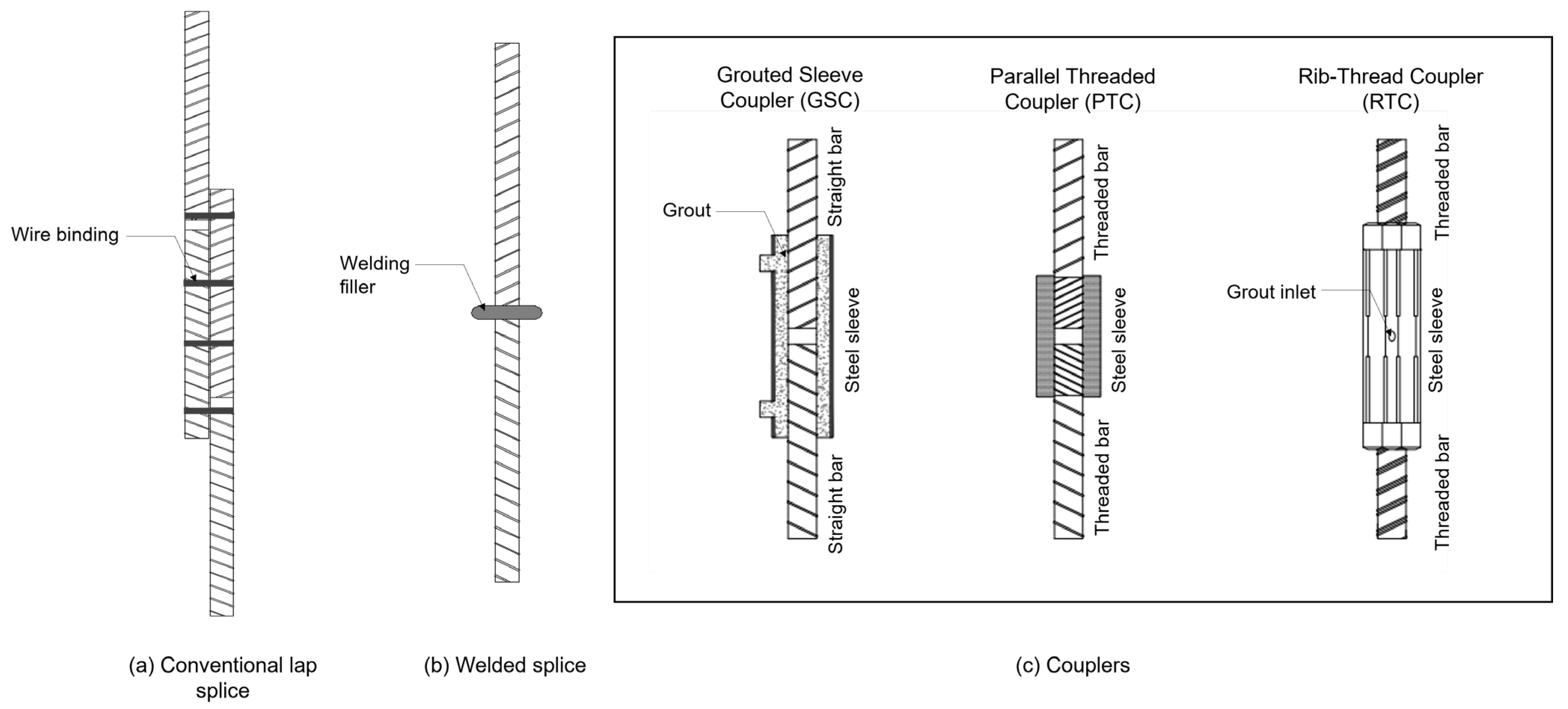
Figure 1. Commonly used rebar connection methods: (a) conventional lap splices, (b) welded splice, (c) couplers.
Smartcities 08 00130 g001
Figure 2. Diaphragm wall construction sequences.
Smartcities 08 00130 g002
Figure 3. Overview of diaphragm wall reinforcement arrangement: (a) 3D model, (b) rebar cage, (c) top-view, (d) additional rebars types, (e) lower cage installation, (f) upper cage installation (modified from [42]).
Smartcities 08 00130 g003
Figure 4. The study’s flowchart.
Smartcities 08 00130 g004
Figure 5. Overview of the existing two-stage integrated optimization framework tailored for diaphragm walls (modified from [8]).
Smartcities 08 00130 g005
Figure 6. An illustration of coupler’s inner gap and its placement within adjacent bars (adapted from [11,12,13,14,15,16,17]).
Smartcities 08 00130 g006
Figure 7. The proposed intelligent rebar optimization core step.
Smartcities 08 00130 g007
Figure 8. The proposed intelligent rebar optimization framework in Python IDE.
Smartcities 08 00130 g008
Figure 9. The end-to-end framework implementation.
Smartcities 08 00130 g009
Figure 10. Cross Island Line route map showing Phases 1 and 2 (adapted from Land Transport Authority, Singapore [51].
Smartcities 08 00130 g010
Figure 11. Reinforcement arrangement of the selected diaphragm wall: (a) dimension, (b) rebar cage section.
Smartcities 08 00130 g011
Figure 12. Comparison of rebar usage and waste generated by stock-length-based and intelligent rebar optimizations.
Smartcities 08 00130 g012
Figure 13. Comparison of cost incurred by stock-length-based and intelligent rebar optimizations.
Smartcities 08 00130 g013
Table 1. A summary of the metaheuristic algorithm tailored for rebar cutting stock problem.
Algorithm(s)Characteristic(s)
Symbiotic Organism Search (SOS) [12]
  • Employs SOS to solve bi-objective rebar cutting plan by generating feasible cutting patterns with minimal waste.
  • Assume a fixed stock-length rebar of 12 m.
Fuzzy Genetic Algorithms (GA) [13]
  • Applies fuzzy GA to determine the best cutting pattern that minimizes waste.
  • Assume a fixed stock-length rebar of 12 m.
Greedy Adaptive Particle Swarm Optimization (PSO) [14]
  • Utilizes a greedy adaptive PSO to optimize cutting pattern and reduce rebar loss.
  • Assume a fixed 9 m stock-length rebar.
Hybrid Particle Swarm Optimization (PSO) [15]
  • Combines column generation, PSO, and best-fit decreasing heuristics to identify valid cutting patterns with minimum waste.
  • Supports multiple stock-length rebars (e.g., 6, 9, 12 m).
Whale Optimization Algorithm (WOA) [11]
  • Employs a pruning-based WOA to simultaneously identify purchasable special lengths and associated cutting patterns to minimize waste.
  • Utilizes special-length rebar ranging from 6 to 12 m in 0.1 m increments.
Table 2. Assigned parameters for WOACSO.
ParameterDescription
Number of iterations (num_iterations)50
Number of whales (num_whales)30
Control modifier a[0, 2]
Spiral parameter l, random[−1, 1]
Minimum available rebar length ( l m i n )6 m
Maximum available rebar length ( l m a x )12 m
Table 3. Standardized rebar specification sheet for the selected diaphragm wall.
DescriptionContents
Larger rebar diameter40 mm
Smaller rebar diameter25 mm
Concrete strength24 MPa
Rebar yield strength500 MPa
Concrete cover50 mm
Maximum rebar length12,000 mm
Rebar unit weight H409.854 kg/m
Rebar unit weight H253.854 kg/m
Inner gap of coupler > H3230 mm
Inner gap of coupler < H3220 mm
Table 4. Standardized data sheet for the selected diaphragm wall layer-wise details.
LayerDiameter (mm)Number of Rebar in Bundle (pcs)Total Bar Length (mm)
A1-8404154,609
A8-9254117,300
B1-5404131,500
D2-7404145,360
D7-9254123,750
E2-3404114,000
E5-7404124,500
F5-7404123,000
J6-7404111,000
Table 5. Summary of CROF results.
LayerDiameter (mm)Purchasable Special-Length (m)Total
Number of Special Lengths (pcs)
Total
Number of Coupler (pcs)
Total
Required Quantity (ton)
Total
Purchased Quantity (ton)
A1-8H401120516422.0143222.22077
A8-9H258.782412.730482.74944
B1-5H4010.51238212.702212.72644
D2-7H4011.416412318.2897118.42304
D7-9H2511.982413.749673.76073
E2-3H40782415.644085.6562
E5-7H408.2123829.87419.93874
F5-7H4011.582419.28029.29232
J6-7H40114104.444154.44415
Total98461588.72989.212
Table 6. Summary of WOACSO results including the identified solutions and wastes.
Diameter (mm)Purchasable Special-Length (m)Number of Bars Needed (pcs)Total Waste (m)Total
Required Quantity (ton)
Total
Purchased Quantity (ton)
Total Waste (ton)
H4011.2285105.31730.4161731.453971.03779
H3211.75915.5354.259794.357860.9807
H2510.3879.33.417733.453570.3584
H2010.3756383.78318.2854519.233400.94794
H1610.4104456.5417.0656717.155010.08933
H1311.473155.388.609148.666740.05760
Total (ton)82.05484.3202.266
Table 7. Summary of rebar usage and waste generated from stock-length-based optimization.
Diameter (mm)Stock-Length (m)Number of Bars Needed (pcs)Total
Required Quantity (ton)
Total
Purchased Quantity (ton)
Total Waste (ton)Number of Splices (pcs)
H40121292142.71954152.7764210.05687943
H3212332.327452.499950.172500
H25122269.4355610.452051.01649123
H201275318.2854522.318924.033470
H1612103017.0656719.528802.463130
H13126968.609148.686080.076940
Total (ton)198.443216.26217.8191066
Table 8. A comparison of the carbon emissions generated by each optimization framework.
Approach/FrameworkNumber of Splices/Coupler (pcs)Rebar Usage (ton)Carbon Emissions (ton CO2-eq)
Stock-length-based optimization1066216.262758
Intelligent optimization615173.532622
Reduction42.73136
Reduction rate (%)19.7617.4
Table 9. Cost component.
Cost ComponentUnit Cost (SGD)
Rebar each ton706.3 [59]
Coupler H40; H25 each piece *15.88; 7.89 [8,60]
Disposal charge per ton28.23
Carbon tax per ton45 [55,56]
* The coupler costs were converted from USD to SGD using an exchange rate of USD 1 = SGD 1.29, as noted in [60].
Table 10. A comparison of existing and proposed studies.
StudiesCharacteristic(s)
Conventional stock-length approaches [12,13,14,15]
  • Focus on discontinuous reinforcement without considering continuous arrangements.
  • Utilize various metaheuristic algorithms for cutting pattern optimization.
  • Assume a fixed stock-length rebar (e.g., 6 m, 9 m, 12 m).
  • Applicable to general reinforced concrete elements.
Author’s previous work (unified two-stage lap splice position adjustment-based framework) [42]
  • Applies special-length rebar prioritization and lap splice position adjustment to reduce cutting waste.
  • Addresses both continuous and discontinuous reinforcement in diaphragm walls.
  • Remains largely manual.
Author’s previous work (unified two-stage coupler integration framework) [8]
  • Applies special-length rebar prioritization and coupler integration to optimize rebar usage and minimize cutting waste.
  • Addresses the continuous and discontinuous reinforcement in diaphragm walls.
  • Remains largely manual.
This study (intelligent unified two-stage coupler integration framework)
  • Applies special-length rebar prioritization and coupler allocation to reduce rebar usage and cutting waste.
  • Addresses the continuous and discontinuous reinforcement in diaphragm walls.
  • Proposes an intelligent optimization framework integrating a metaheuristic (WOA) to simultaneously identify optimal purchasable rebar lengths and corresponding cutting patterns that yield minimum waste.
Table 11. Assigned hyperparameters for each framework.
Algorithm(s)Population SizeNumber of IterationsCrossover RateMutation RateInertia Weight (w)Cognitive Weight (c1)Social Weight (c2)
GA30500.80.15---
PSO3050--0.71.51.5
WOACSO3050-----
Table 12. Resulted waste from each framework.
Diameter (mm)GAPSOWOACSO
Bar Length (m)Quantity (pcs)Waste (m)Bar Length (m)Quantity (pcs)Waste (m)Bar Length (m)Quantity (pcs)Waste (m)
H4012279261.3212279261.3211.2285105.32
Waste rate (%)7.817.813.41
Disclaimer/Publisher’s Note: The statements, opinions and data contained in all publications are solely those of the individual author(s) and contributor(s) and not of MDPI and/or the editor(s). MDPI and/or the editor(s) disclaim responsibility for any injury to people or property resulting from any ideas, methods, instructions or products referred to in the content.