
Smart Grid Resilience for Grid-Connected PV and Protection Systems under Cyber Threats

 ,
,  , and
, and
Abstract
:1. Introduction
1.1. Motivation
1.2. Literature Review
1.3. Contributions
- Examine and investigate the impact of different cyber attacks (FDI, DOS, and MITM) on smart PV control and modern OCR protection systems within the IEC61850 and GOOSE protocols.
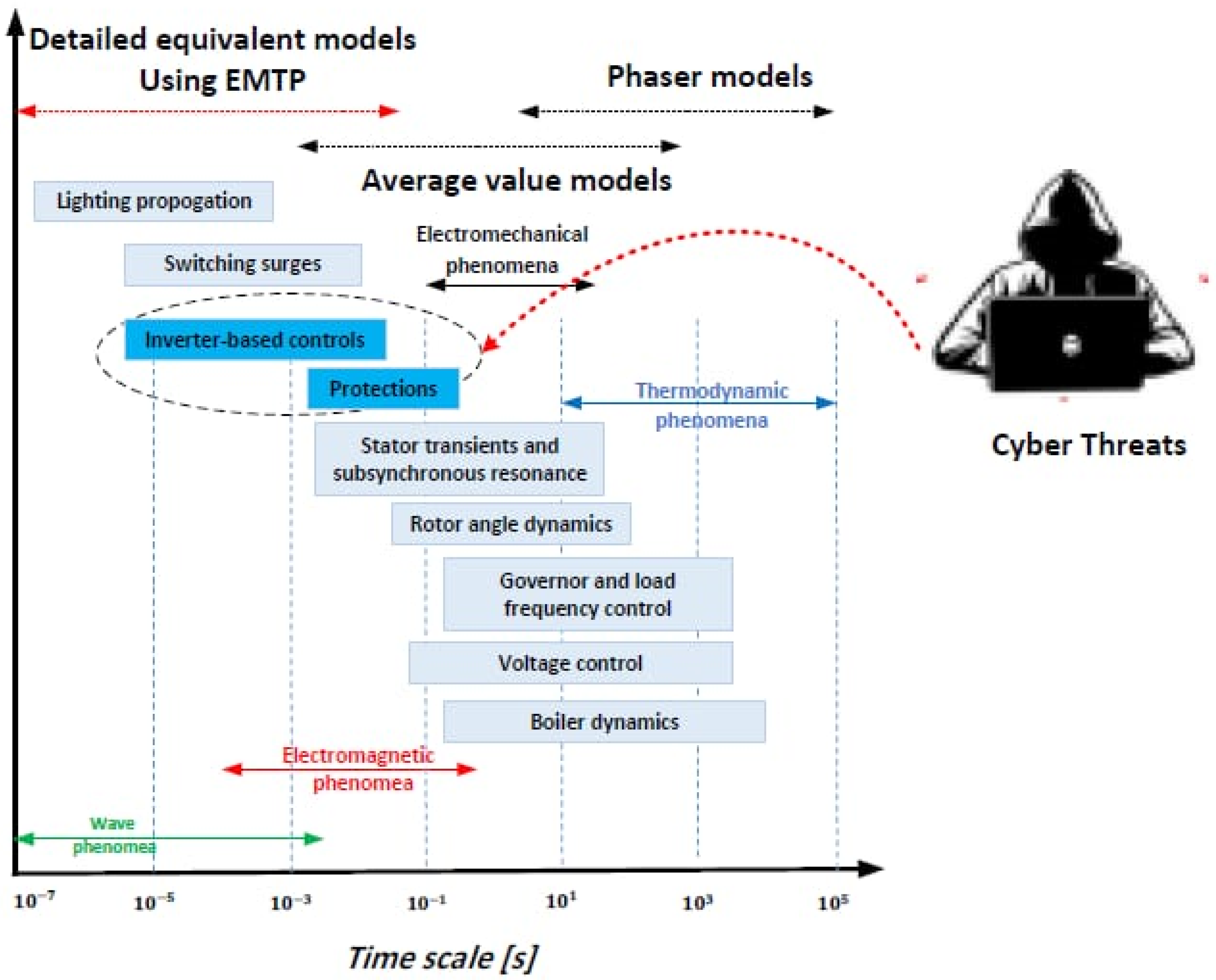
- Provide insights into the electrical and electromagnetic aspects of the cyber attack’s impact on a real network parameter.
- Assess the consequences of the cyber attack on the power grid on the transient behavior of the smart PV control and modern OCR protection systems.
- Model a realistic power network using EMTP for studying transient events and periods under different grid operation scenarios: normal operation, normal operation with irradiation drops, various cyber attacks at smart inverters, and OCR during physical fault conditions.
2. Problem Statement and Power Grid Methodology
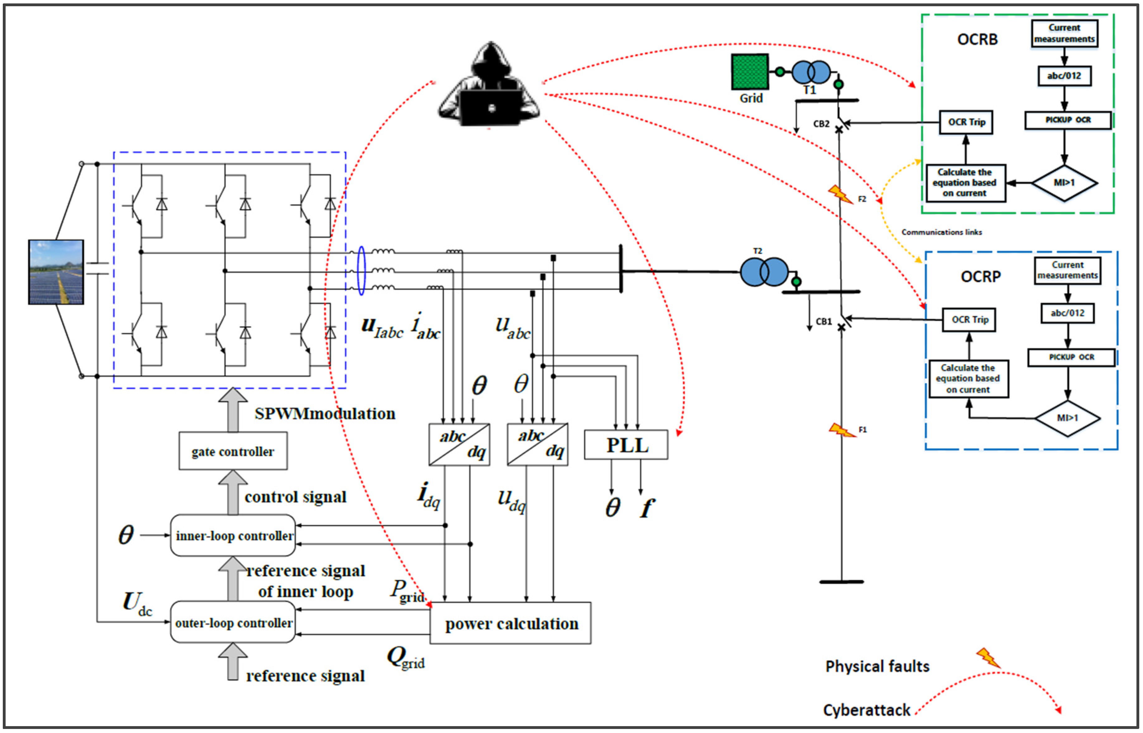
3. Proposed Smart Power Network and Cyber Modeling
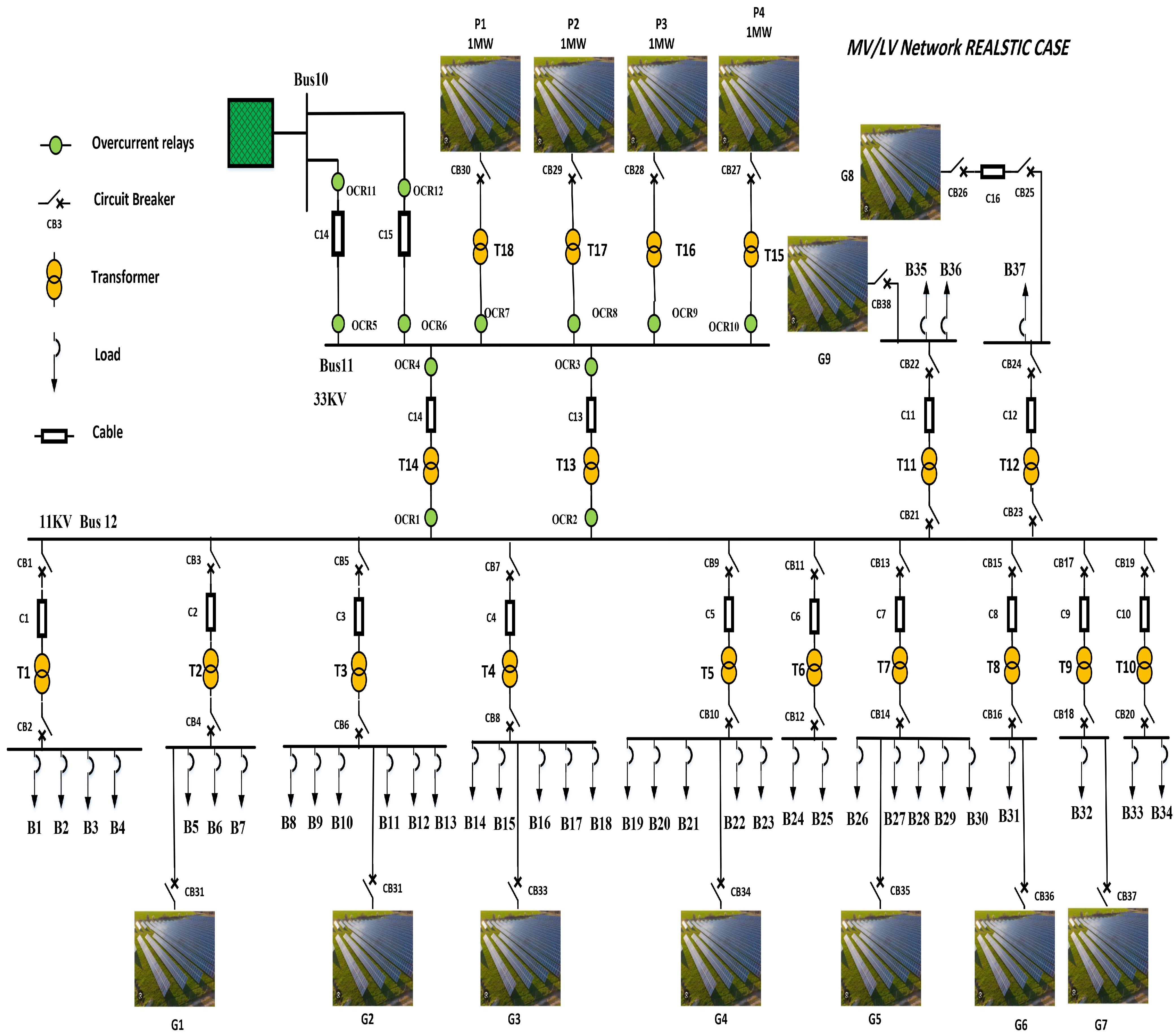
3.1. The Proposed Smart Power Grid Model
3.2. Cyber-Attack Modeling
- Man-in-the-Middle (MITM): The attacker gains access to communication channels, enabling them to delay or block certain messages.
- False Data Injection (FDI): This attack violates the system’s integrity by injecting fabricated data to alter the setpoints and protection setting.
- Denial-of-Service (DOS) Attack: The attacker isolates one or several grid components, preventing them from acting according to the fault occurrence, which will compromise the stability of the grid.
3.2.1. Cyber Threats on Power Protection System (OCR)
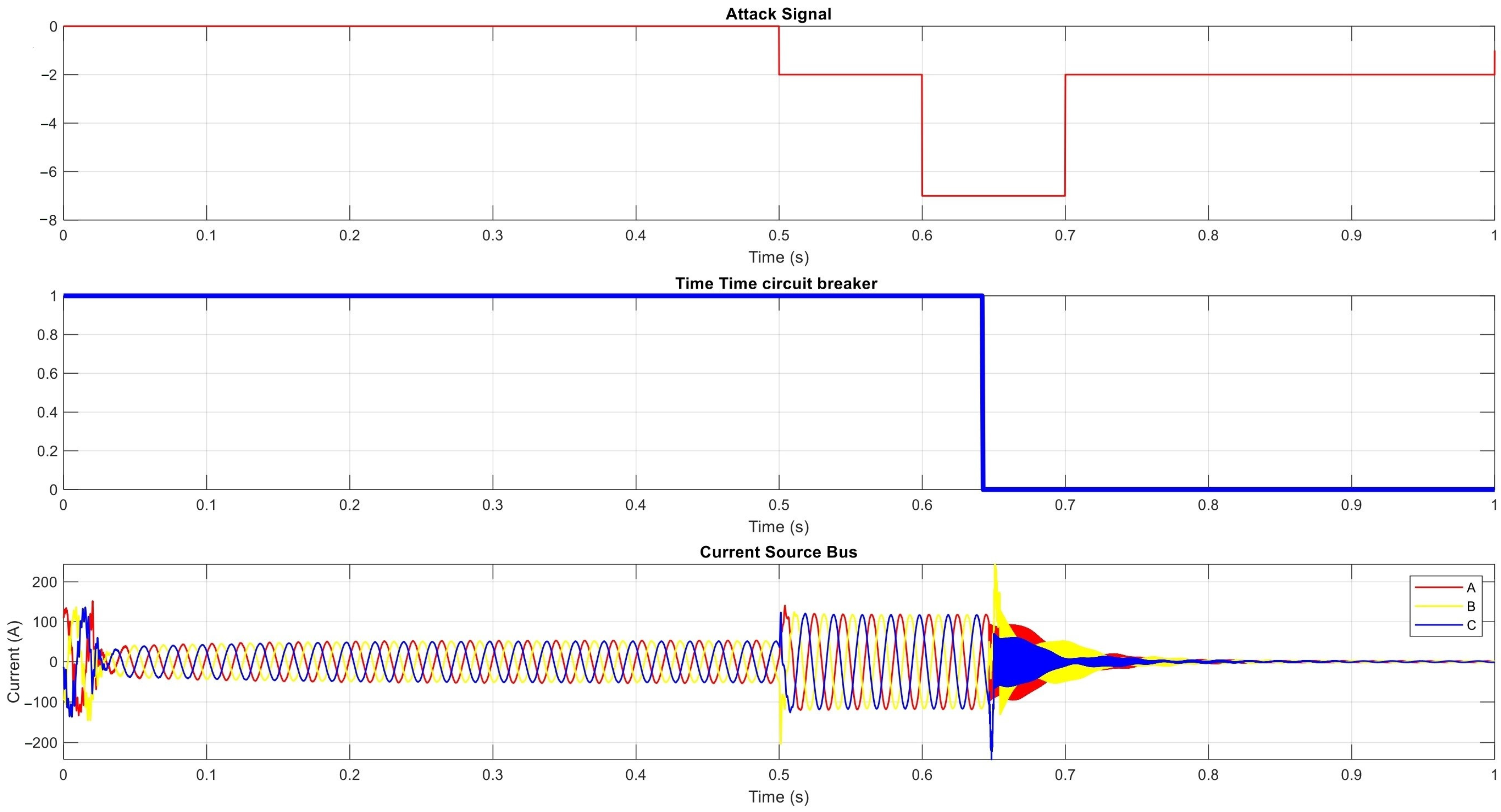
- Manipulating Group Settings: The attacker does not allow the adaptive OCRs to change the group setting or postpone that change for a certain amount of time (FDI).
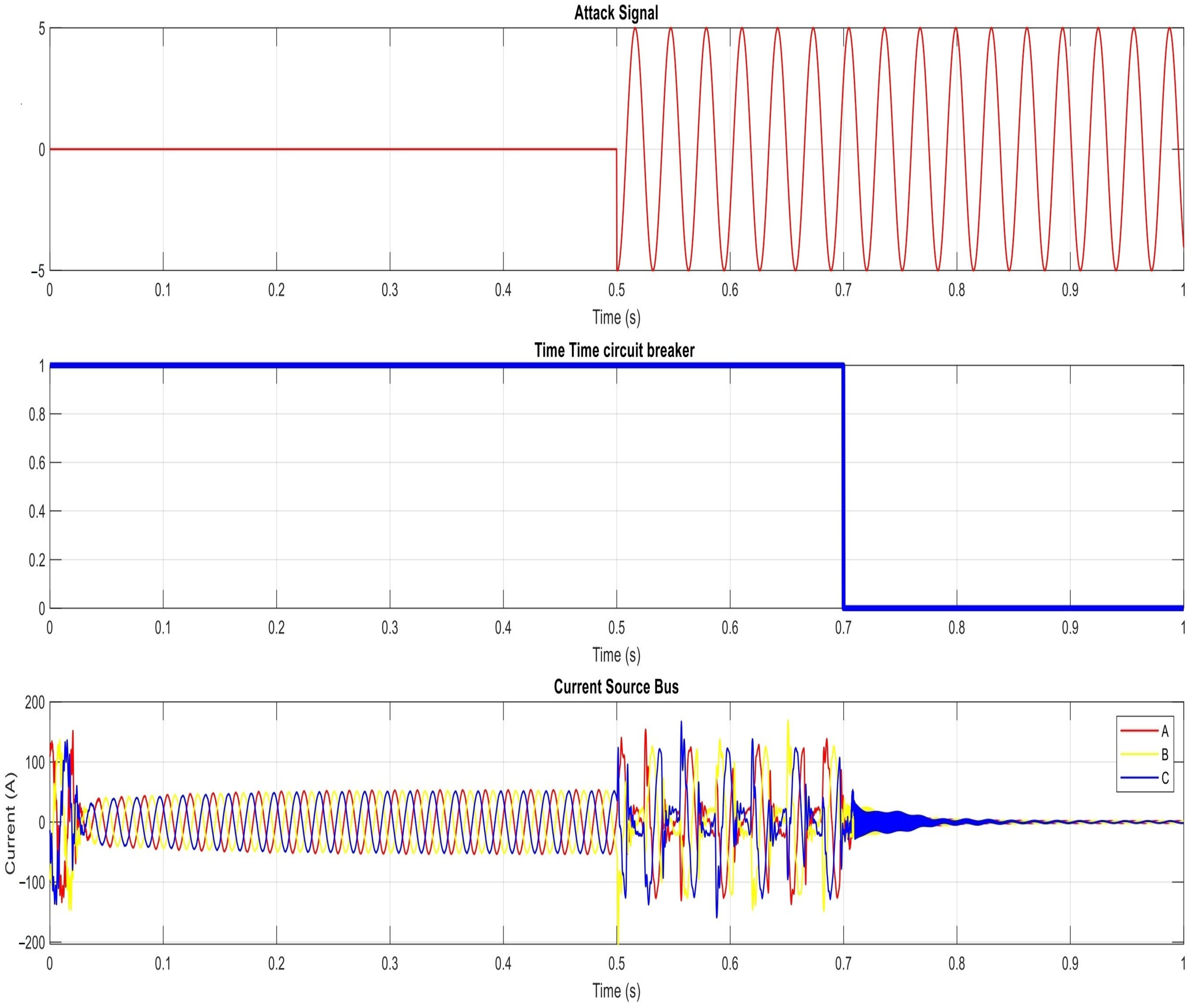
- Delaying Fault Messaging: The attacker’s goal is to delay the communication carrying information about a detected physical fault by using the MITM attack. Such a scenario can lead to instability of the grid as it loses the ability to respond in time for any fault.
3.2.2. Cyber Threats on the Smart PV Inverters
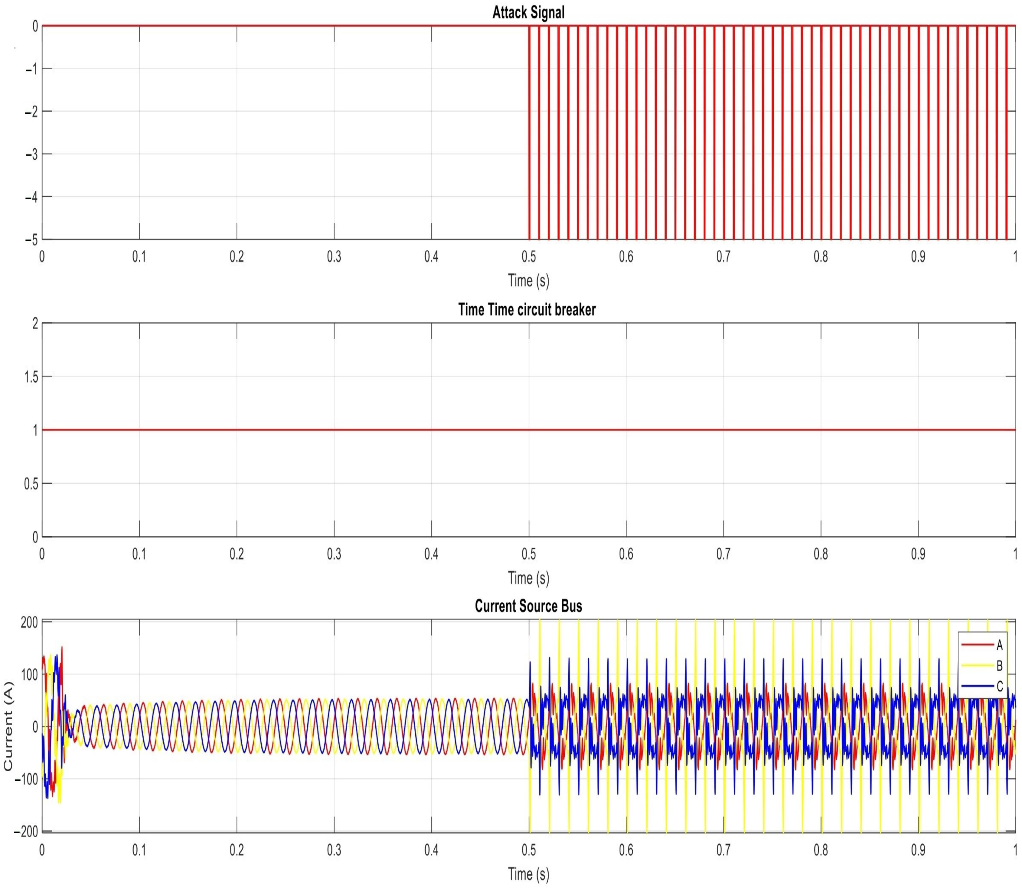
- Continuous Pulse Signal: The attacker has the ability to periodically introduce malicious vectors, which turn the transmitted data into a periodic square wave signal.
- Scaling Signal: This form of attack has the potential to modify the signal through the utilization of a scaling attack factor.
- Sine Signal: The original data are modified using a sinusoidal signal with an amplitude factor.
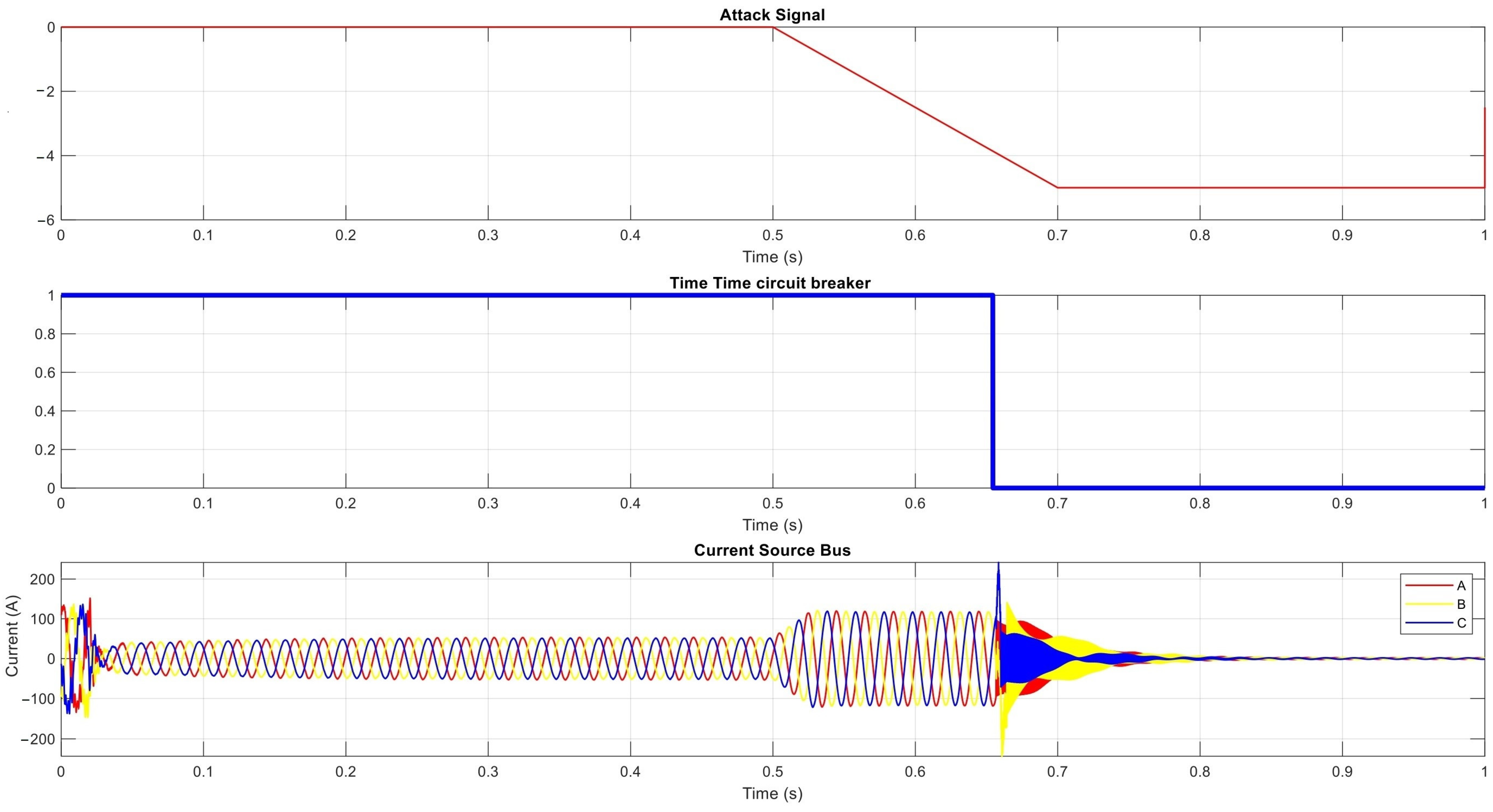
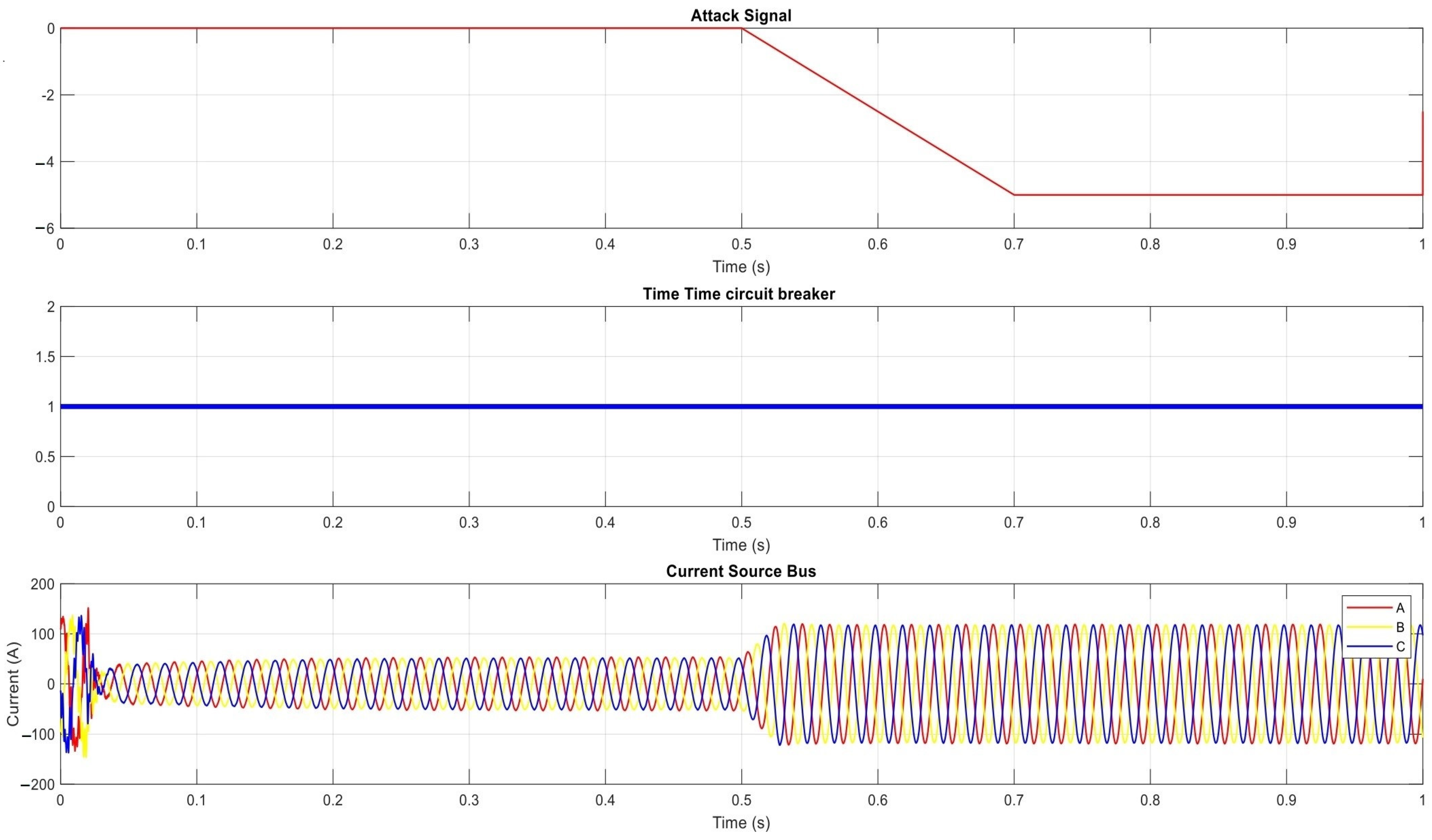
- Ramp Signal: The control signal will take the shape of a ramp waveform signal.
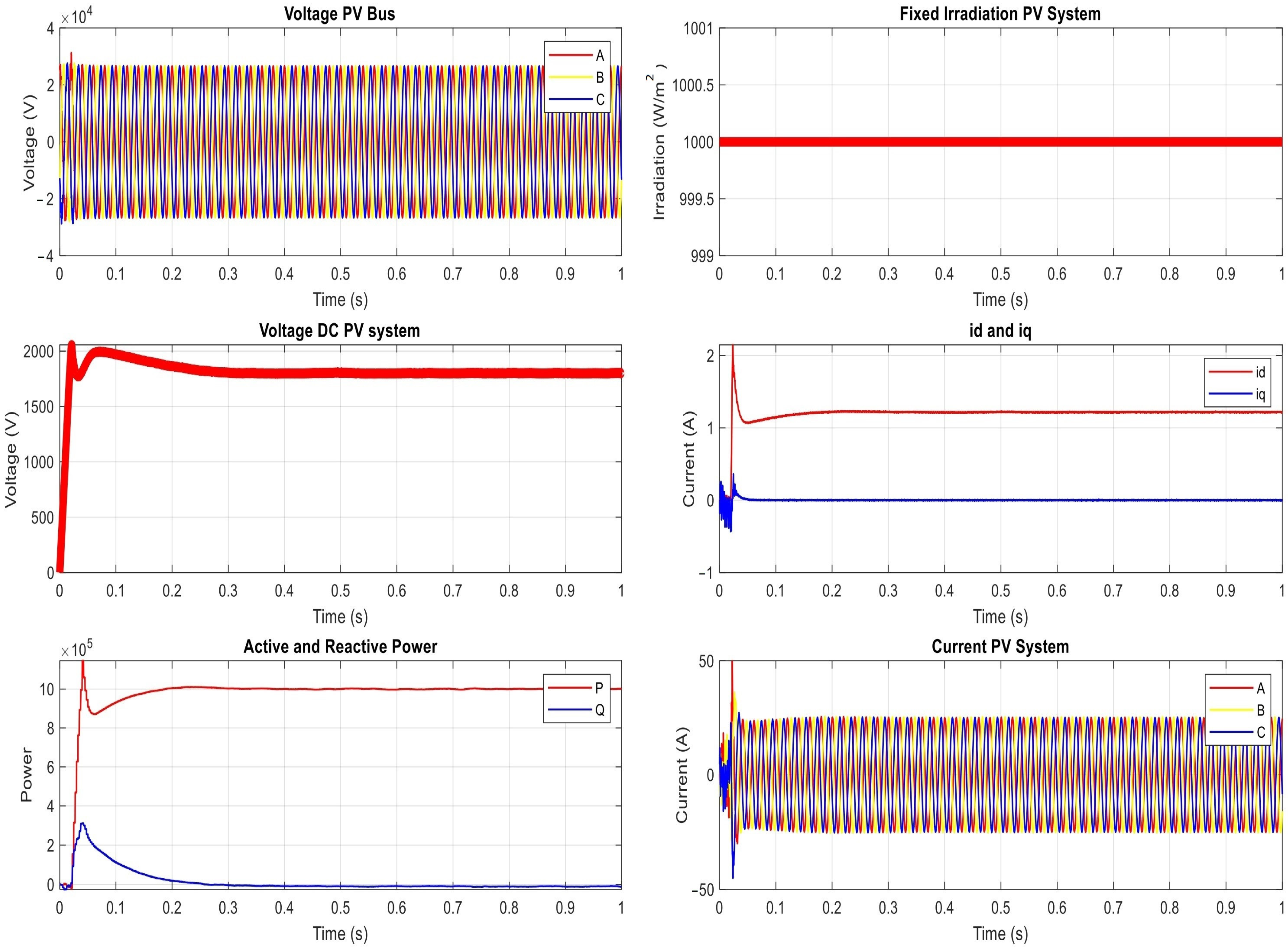
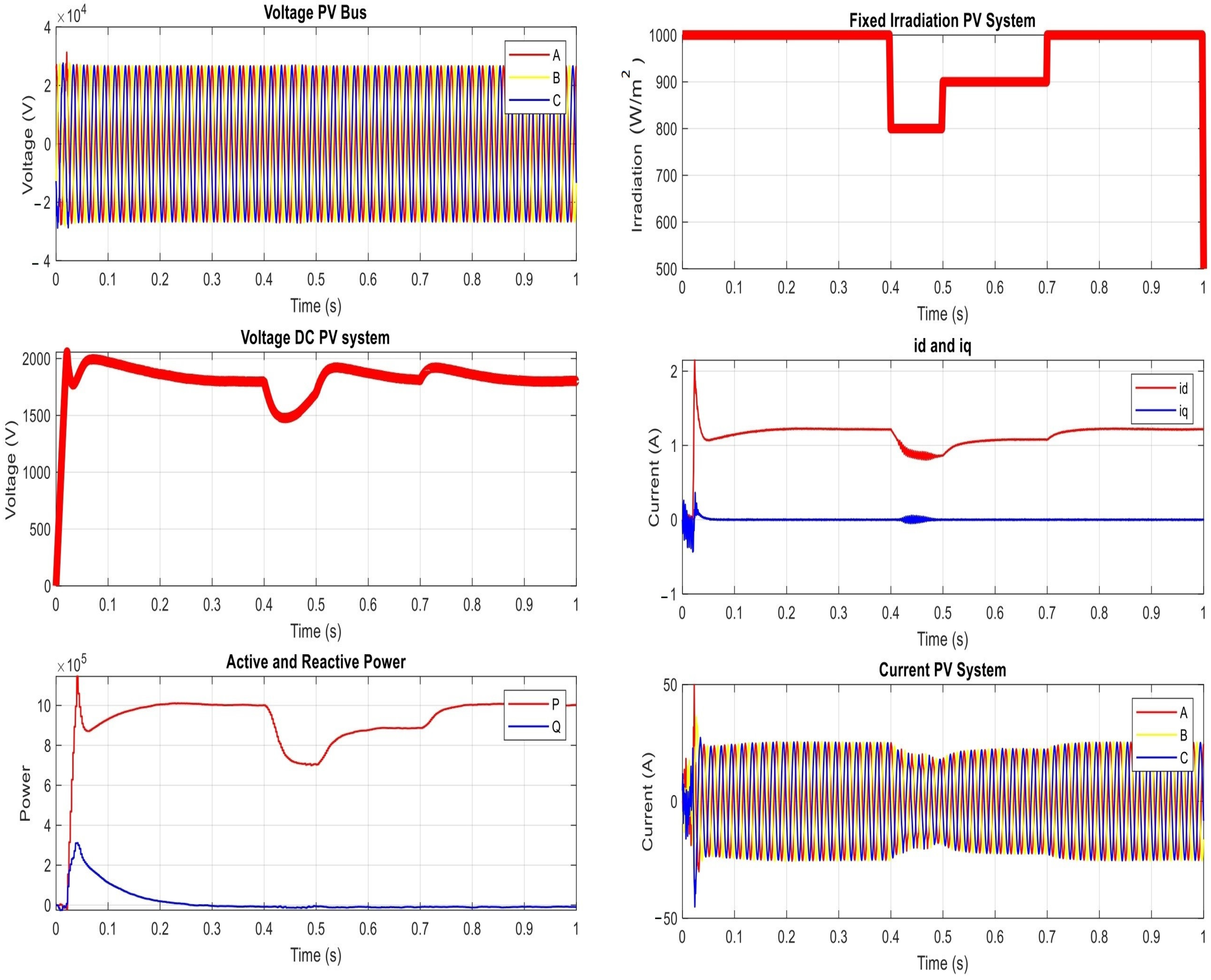
4. Results
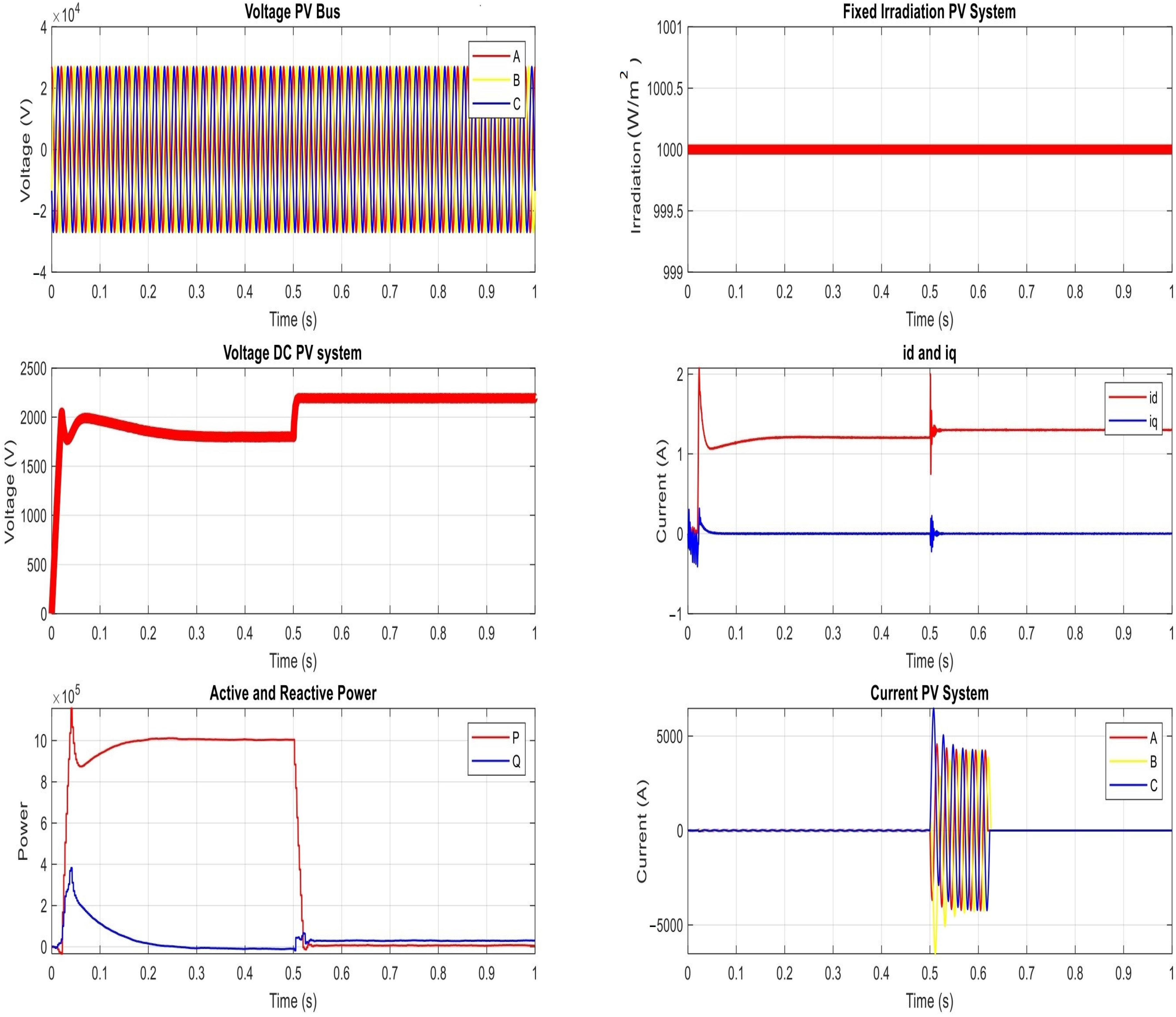
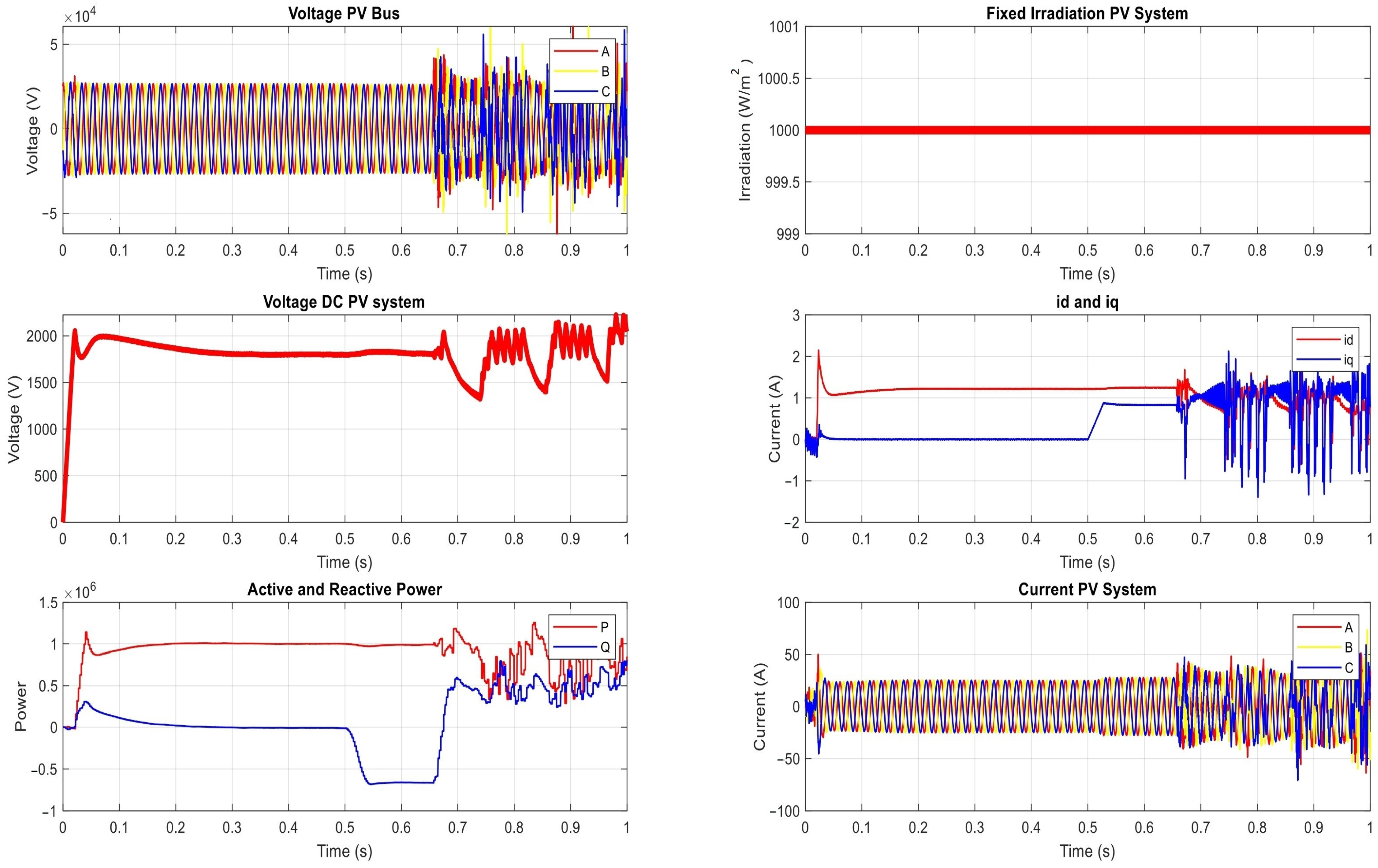
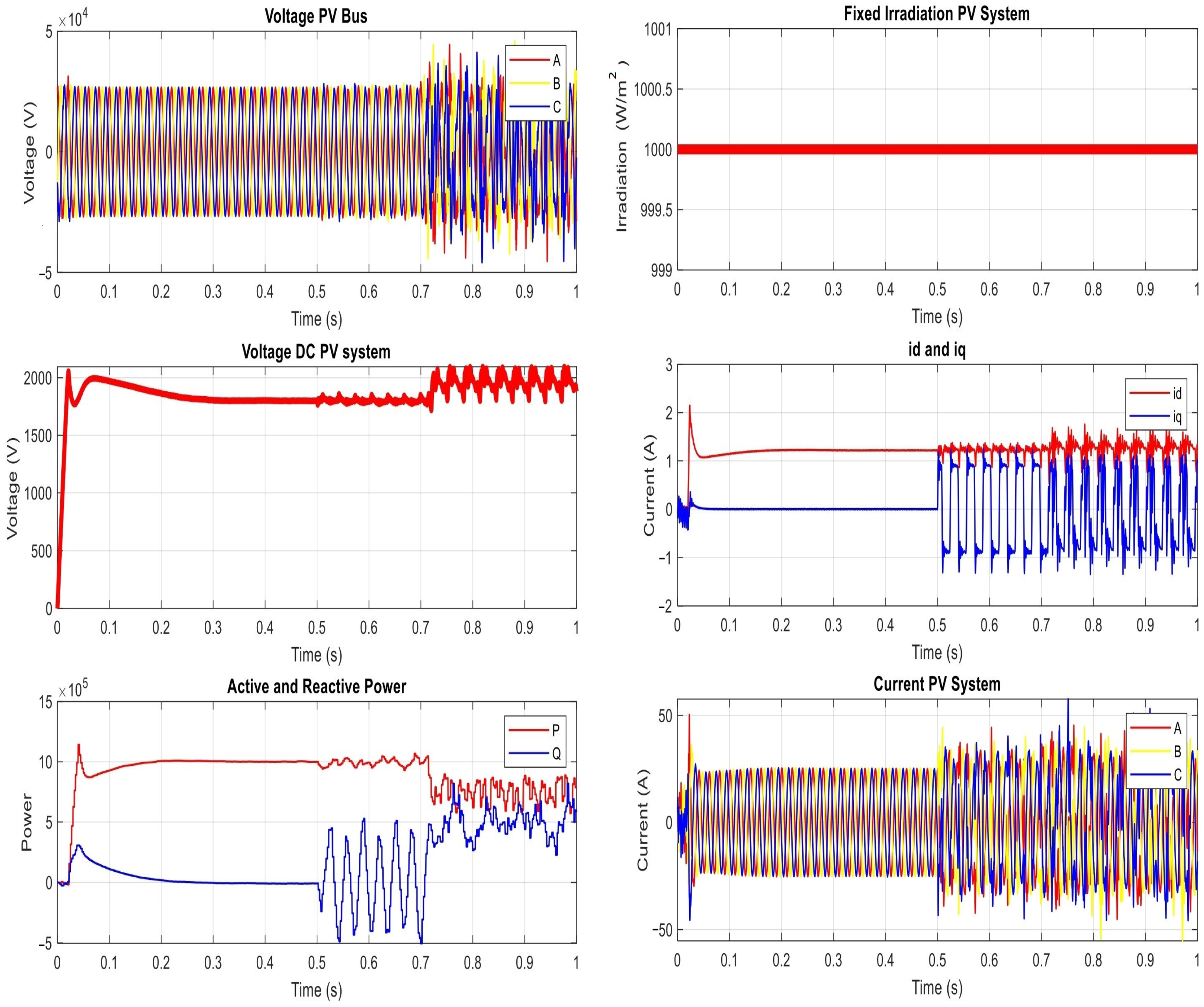
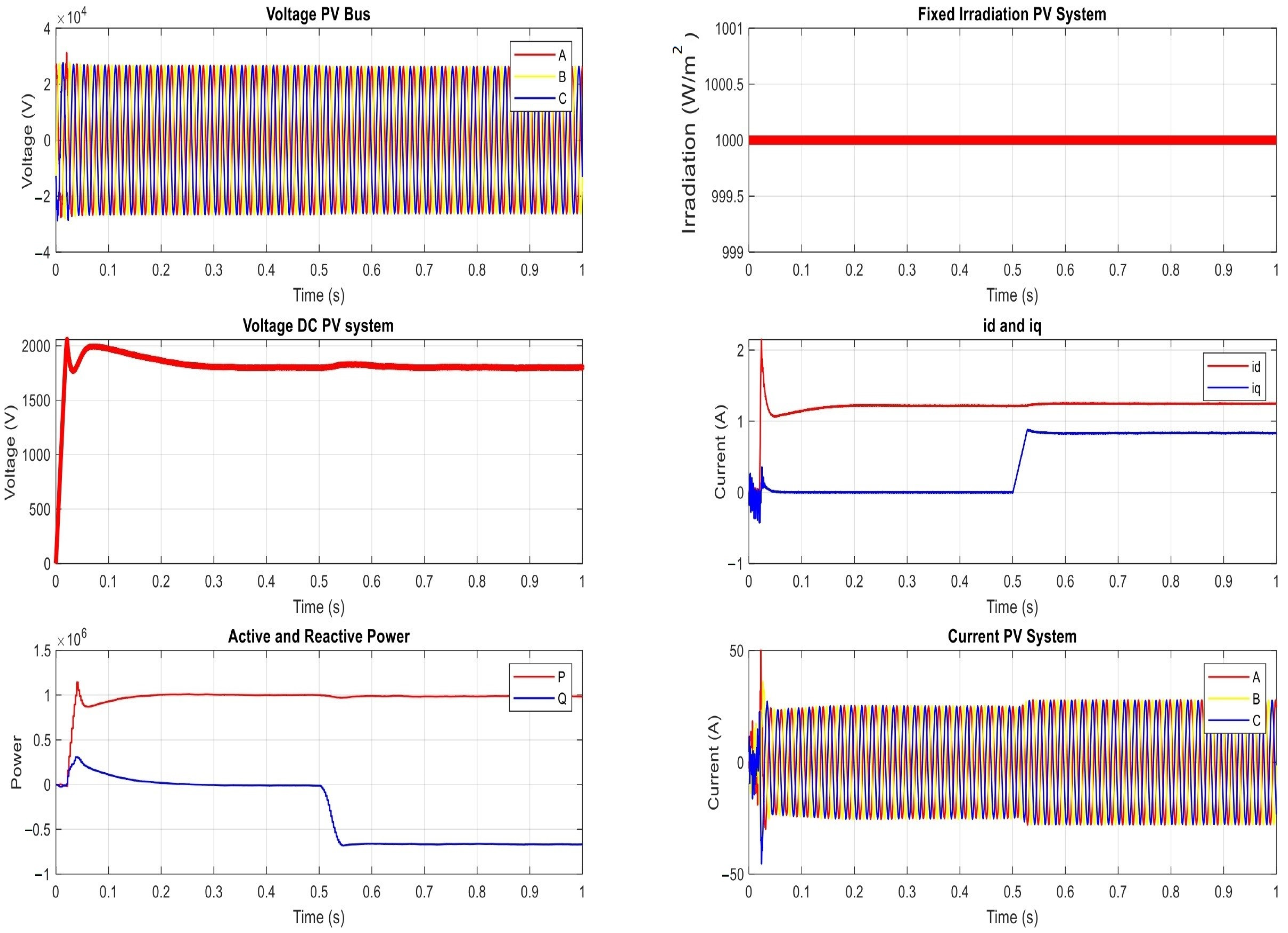
- The voltage on the PV bus (or the bus of Point of Common Coupling (PCC)).
- The DC voltage on the PV system (as measured on the inverter).
- The AC current of the PV system (as measured on the inverter).
- The level of the irradiation.
- The direct and quadratic current ( and ) at the grid.
- The active and reactive power at the grid.
4.1. The Proposed Power Network under Normal Operation Condition
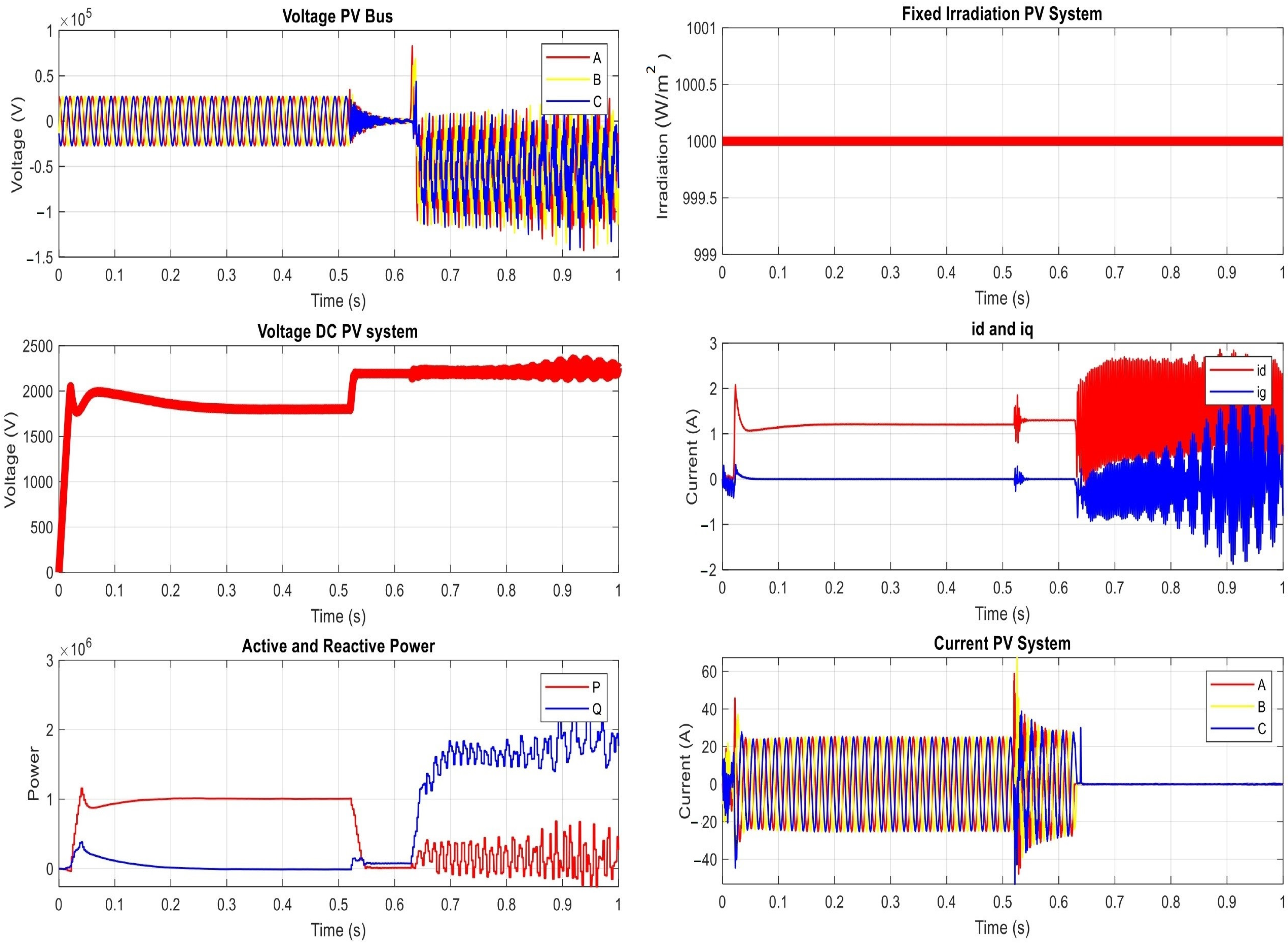
4.2. Results of Cyber Threats on Power Protection System (OCR)
- Manipulating Group Settings:
- Delaying Fault Messaging
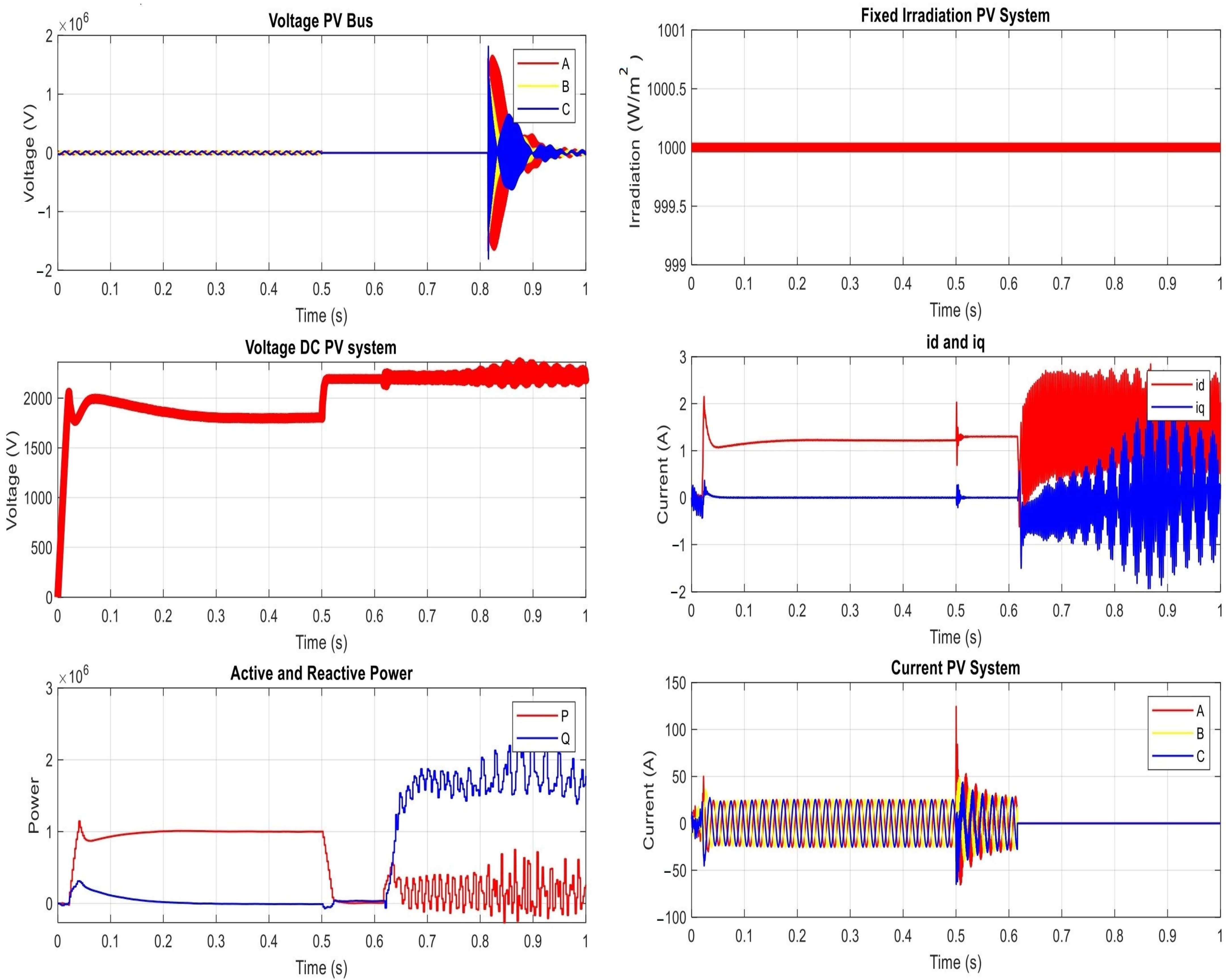
4.3. Results of Cyber Threats on the Smart PV Inverters
- Continuous Pulse Signal Attack
- Scaling Signal Attack
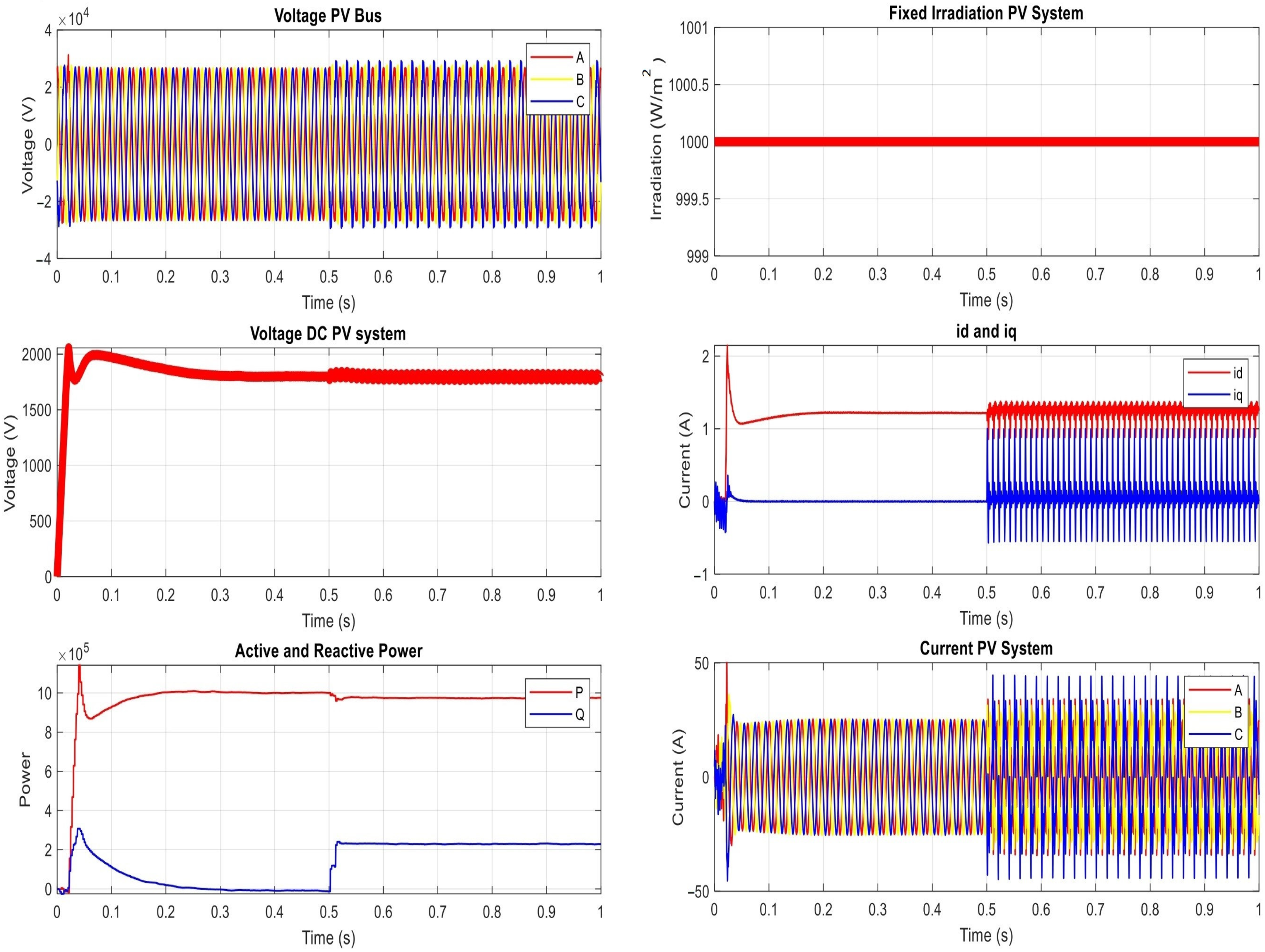
- Sine Signal Attack
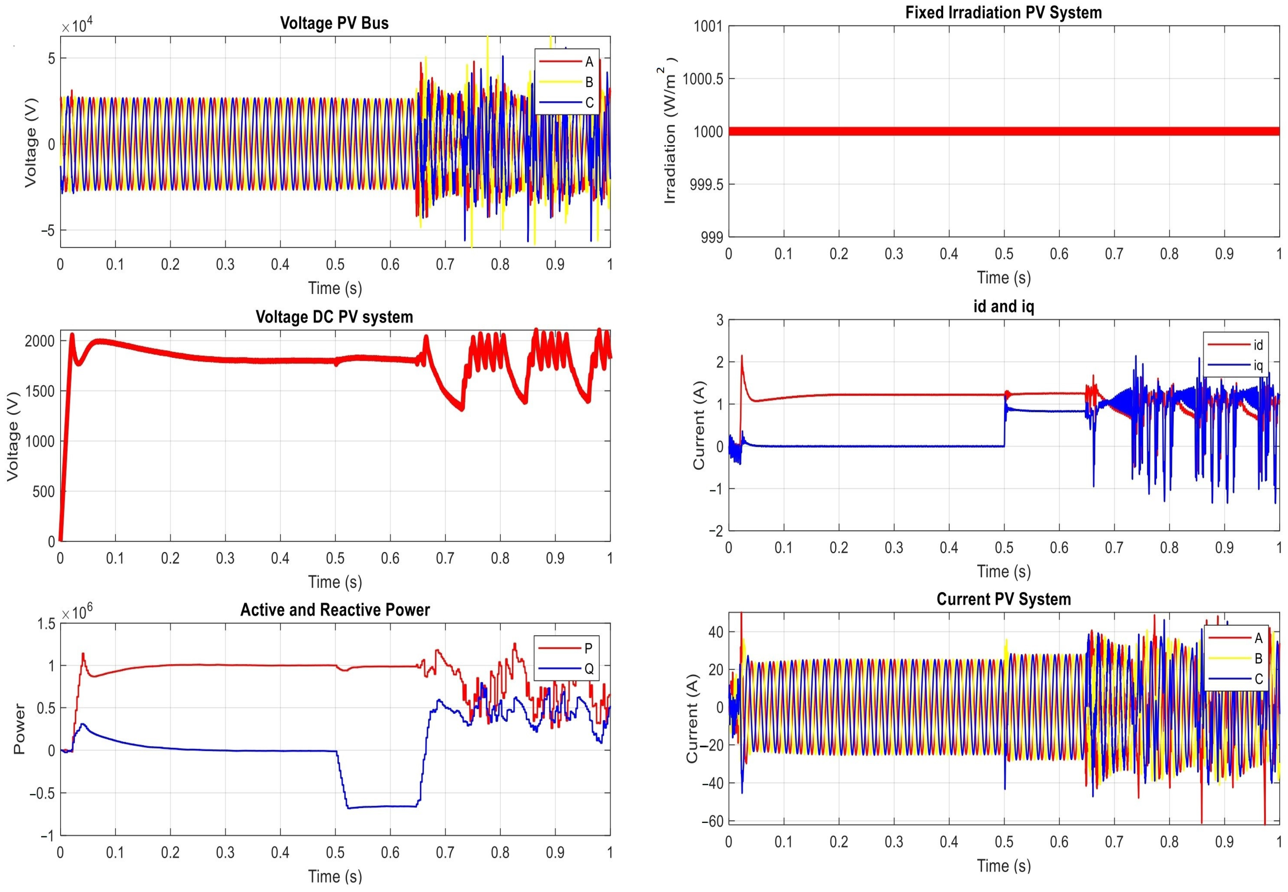
- Ramp Signal Attack
4.4. Discussion
5. Conclusions
Author Contributions
Funding
Data Availability Statement
Acknowledgments
Conflicts of Interest
References
- Holderbaum, W.; Alasali, F.; Sinha, A. Energy Forecasting and Control Methods for Energy Storage Systems in Distribution Networks, Predictive Modelling and Control Techniques, 1st ed.; Springer: Cham, Switzerland, 2023. [Google Scholar]
- Brahma, S.M.; Girgis, A.A. Development of adaptive protection scheme for distribution systems with high penetration of distributed generation. IEEE Trans. Power Deliv. 2004, 19, 56–63. [Google Scholar] [CrossRef]
- Ahmed, A.; Krishnan, V.V.; Foroutan, S.A.; Touhiduzzaman, M.; Rublein, C.; Srivastava, A.; Suresh, S. Cyber physical security analytics for anomalies in transmission protection systems. IEEE Trans. Ind. Appl. 2019, 55, 6313–6323. [Google Scholar] [CrossRef]
- Olowu, T.O.; Dharmasena, S.; Jafari, H.; Sarwat, A. Investigation of false data injection attacks on smart inverter settings. In Proceedings of the 2020 IEEE CyberPELS (CyberPELS), Miami, FL, USA, 13 October 2020; pp. 1–6. [Google Scholar]
- Peng, S.; Liu, M.; Zuo, K.; Tan, W.; Deng, R. Stealthy Data Integrity Attacks Against Grid-tied Photovoltaic Systems. In Proceedings of the 2023 IEEE 6th International Conference on Industrial Cyber-Physical Systems (ICPS), Wuhan, China, 8–11 May 2023; pp. 1–7. [Google Scholar]
- Yousefi kia, M.; Saniei, M.; Seifossadat, S.G. A novel cyber-attack modelling and detection in overcurrent protection relays based on wavelet signature analysis. IET Gener. Transm. Distrib. 2023, 17, 1585–1600. [Google Scholar] [CrossRef]
- Zhou, J.; Feng, C.; Su, Q.; Jiang, S.; Fan, Z.; Ruan, J.; Sun, S.; Hu, L. The Multi-Objective Optimization of Powertrain Design and Energy Management Strategy for Fuel Cell–Battery Electric Vehicle. Sustainability 2022, 14, 6320. [Google Scholar] [CrossRef]
- Lu, D.; Yi, F.; Hu, D.; Li, J.; Yang, Q.; Wang, J. Online optimization of energy management strategy for FCV control parameters considering dual power source lifespan decay synergy. Appl. Energy 2023, 348, 121516. [Google Scholar] [CrossRef]
- Nasirian, V.; Shafiee, Q.; Guerrero, J.M.; Lewis, F.L.; Davoudi, A. Droop-Free Distributed Control for AC Microgrids. IEEE Trans. Power Electron. 2016, 31, 1600–1617. [Google Scholar] [CrossRef]
- Rosero, C.X.; Velasco, M.; Martí, P.; Camacho, A.; Miret, J.; Castilla, M. Active Power Sharing and Frequency Regulation in Droop-Free Control for Islanded Microgrids Under Electrical and Communication Failures. IEEE Trans. Ind. Electron. 2020, 67, 6461–6472. [Google Scholar] [CrossRef]
- Mahmud, M.A.; Hossain, M.J.; Pota, H.R.; Oo, A.M.T. Robust Nonlinear Distributed Controller Design for Active and Reactive Power Sharing in Islanded Microgrids. IEEE Trans. Energy Convers. 2014, 29, 893–903. [Google Scholar] [CrossRef]
- Rey, J.M.; Vergara Barrios, P.; Castilla, M.; Camacho, A.; Velasco, M.; Martí, P. Droop-free hierarchical control strategy for inverter-based AC microgrids. IET Power Electron. 2020, 13, 1403–1415. [Google Scholar] [CrossRef]
- Sowa, I.; Monti, A. On Dynamics of Communication-Based Distributed Consensus Control in Islanded Microgrids. In Proceedings of the 2022 International Conference on Smart Energy Systems and Technologies (SEST), Eindhoven, The Netherlands, 5–7 September 2022. [Google Scholar]
- Majumder, S.; Vosughi, A.; Mustafa, H.; Warner, T.; Srivasava, A. On the Cyber-Physical Needs of DER-based Voltage Control/Optimization Algorithms in Active Distribution Network. IEEE Access 2022, 10, 64397–64429. [Google Scholar] [CrossRef]
- Liu, X.; Li, H. Data-driven Cyberphysical Anomaly Detection for Microgrids with GFM Inverters. IEEE Open J. Power Electron. 2023, 4, 498–511. [Google Scholar] [CrossRef]
- Kaewnukultorn, T.; Sepúlveda-Mora, S.B.; Broadwater, R.; Zhu, D.; Tsoutsos, N.G.; Hegedus, S. Smart PV Inverter Cyberattack Detection using Hardware-in-the-Loop Test Facility. IEEE Access 2023, 99, 90766–90779. [Google Scholar] [CrossRef]
- Bamigbade, A.; Dvorkin, Y.; Karri, R. Cyberattack on phase-locked loops in inverter-based energy resources. IEEE Trans. Smart Grid 2023, 1. [Google Scholar] [CrossRef]
- Zhang, J.; Guo, L.; Ye, J.; Giani, A.; Elasser, A.; Song, W.; Mantooth, H.A. Machine Learning-based Cyber-attack Detection in Photovoltaic Farms. IEEE Open J. Power Electron. 2023, 4, 653–673. [Google Scholar] [CrossRef]
- Piesciorovsky, E.C.; Hahn, G.; Hink, R.B.; Werth, A.; Lee, A. Electrical substation grid testbed for DLT applications of electrical fault detection, power quality monitoring, DERs use cases and cyber-events. Energy Rep. 2023, 10, 1099–1115. [Google Scholar] [CrossRef]
- Aftab, M.A.; Chawla, A.; Vergara, P.P.; Ahmed, S.; Konstantinou, C. Volt/VAR Optimization in the Presence of Attacks: A Real-Time Co-Simulation Study. In Proceedings of the IEEE International Conference on Communications, Control, and Computing Technologies for Smart Grids (SmartGridComm), Aachen, Germany, 25–28 October 2021. [Google Scholar]
- Rajaee, M.; Mazlumi, K. Multi-Agent Distributed Deep Learning Algorithm to Detect Cyber-Attacks in Distance Relays. IEEE Access 2023, 11, 10842–10849. [Google Scholar] [CrossRef]
- Jadidi, S.; Badihi, H.; Zhang, Y. Design of an intelligent hybrid diagnosis scheme for cyber-physical PV systems at the microgrid level. Int. J. Electr. Power Energy Syst. 2023, 150, 109062. [Google Scholar] [CrossRef]
- Sowa, I.; Monti, A. Distributed Consensus Control Supported by High Reporting Rate Meters in Inverter-Based Cyber-Physical Microgrids. IEEE Access 2023, 11, 48305–48321. [Google Scholar] [CrossRef]
- Elrawy, M.F.; Tekki, E.; Hadjidemetriou, L.; Laoudias, C.; Michael, M.K. Protection and Communication Model of Intelligent Electronic Devices to Investigate Security Threats. In Proceedings of the 2023 IEEE Power & Energy Society Innovative Smart Grid Technologies Conference (ISGT), Washington, DC, USA, 16–19 January 2023; pp. 1–5. [Google Scholar]
- Zaki, M.; El Sehiemy, R.; Megahed, T.; Asano, T.; Abdelkader, S. A proposed fault identification-based fuzzy approach for active distribution networks with photovoltaic systems. Measurement 2023, 223, 113678. [Google Scholar] [CrossRef]
- De Oliveira-De Jesus, P.M.; Sorrentino, E. Methodology to assess performance indexes for sensitivity, selectivity, and speed of coordination of directional overcurrent protections. Electr. Power Syst. Res. 2022, 213, 108758. [Google Scholar] [CrossRef]
- Gonzalez, R.; Aryasomyajula, V.; Ayyagari, K.; Gatsis, N.; Alamaniotis, M.; Ahmed, S. Modeling and studying the impact of dynamic reactive current limiting in grid-following inverters for distribution network protection. Electr. Power Syst. Res. 2023, 224, 109609. [Google Scholar] [CrossRef]
- Pramanik, A.S.; Sepasi, S. Transient Behavior Analysis of Microgrids in Grid-Connected and Islanded Modes: A Comparative Study of LVRT and HVRT Capabilities. Clean Technol. 2023, 5, 1287–1303. [Google Scholar] [CrossRef]
- Kumar, J.; Sikdar, B.; Kundur, D. Three-Phase Radial EMTP and Stealthy Attack Detector for Distribution Systems. In Proceedings of the IEEE International Conference on Power Electronics, Drives and Energy Systems (PEDES), Jaipur, India, 16–19 December 2020. [Google Scholar]


| Ref. | Year | Protocol | Type of Cyber Attack | Study Area | Standard or Real Network | (DERs) TYPE | Physical Software | Cyber Software | |
|---|---|---|---|---|---|---|---|---|---|
| Protection System | Control System | ||||||||
| [3] | 2019 | PMU | Data spoofing, Man-in-the-Middle (MITM) | √ | × | IEEE-14 | × | Real-Time Digital Simulator (RTDS) | √ |
| [4] | 2020 | × | False Data Injection (FDI) | × | √ | IEEE-8500 | PV | OpenDSS and MATLAB | × |
| [5] | 2023 | × | Stealthy Data Integrity Attacks (DIA) | × | √ | IEEE-34 | PV | Real-time Typhoon testbed | × |
| [6] | 2023 | × | FDI attacks and Denial of Service (DOS) | √ | × | IEEE-14 | × | MATLAB/Simulink | × |
| [7] | 2023 | IEC61850 | FDI | √ | × | CIGRE | PV | Real-Time Digital Simulator (RTDS) | × |
| [16] | 2023 | × | DoS, intermittent attack, and modification attacks | × | √ | × | PV | Power Hardware-2in- the-Loop (P-HIL) test | × |
| [17] | 2023 | PMUs | DoS and DIA | × | √ | IEEE-14 | PV | EMTP MATLAB/Simulink | × |
| [18] | 2023 | PMUs | DIA, replay attacks, Sophisticated attacks | × | √ | IEEE-37 | PV | OPAL-RT | × |
| [19] | 2023 | IEC61850 | FDI and DOS | √ | × | × | × | OPAL-RT | × |
| [20] | 2023 | IEC 61850 | FDI, DOS | √ | √ | IEEE-34 bus | PV | OPAL-RT | √ |
| [21] | 2023 | × | FDI | √ | × | IEEE-118 bus, | × | MATLAB | × |
| [22] | 2023 | × | DIA | × | √ | Microgrid benchmark | PV | × | × |
| [15] | 2023 | PMUs | DOS | × | √ | 28 bus test system | PV | MATLAB | × |
| [23] | 2023 | IEC61850 | FDIA | √ | √ | × | PV | OPAL-RT. | × |
| [24] | 2023 | GOOSE | FDIA | √ | × | × | × | MATLAB/Simulink | × |
| Proposed study | IEC61850 GOOSE | FDI, DOS, MITM | √ | √ | Realistic power grid | PV | EMTP | √ | |
| Area | PV Power (KWp) | Energy Production (kWh/Year) |
|---|---|---|
| P1 | 1011.84 | 1,880,504 |
| P2 | 1011.84 | 1,880,504 |
| P3 | 1011.84 | 1,880,504 |
| P4 | 980.22 | 1,821,738 |
| G1 | 22.320 | 36.873 |
| G2 | 22.320 | 36.873 |
| G3 | 22.320 | 36.873 |
| G4 | 22.320 | 36.873 |
| G5 | 23.560 | 41.324 |
| G6 | 13.640 | 23.925 |
| G7 | 22.940 | 38.310 |
| G8 | 23.560 | 39.345 |
| G9 | 22.320 | 41.939 |
| Building | CB Rating | Building | CB Rating |
|---|---|---|---|
| B1 | 1250 | B19 | 400 |
| B2 | 600 | B20 | 400 |
| B3 | 125 | B21 | 125 |
| B4 | 125 | B22 | 250 |
| B5 | 1250 | B23 | 250 |
| B6 | 400 | B24 | 2500 |
| B7 | 60 | B25 | 2500 |
| B8 | 150 | B26 | 400 |
| B9 | 200 | B27 | 1250 |
| B10 | 125 | B28 | 250 |
| B11 | 400 | B29 | 400 |
| B12 | 200 | B30 | 250 |
| B13 | 400 | B31 | 800 |
| B14 | 250 | B32 | 3200 |
| B15 | 400 | B33 | 2000 |
| B16 | 250 | B34 | 2500 |
| B17 | 160 | B35 | 2500 |
| B18 | 400 | B36 | 2500 |
| B37 | 3200 |
| Vulnerability | Description | Relevance to Cyber Attacks |
|---|---|---|
| Vulnerabilities in Communication Architecture | Using protocols like IEC61850 that has loose cyber constraints and insufficient security measures. | FDI: Exploitation of un-encrypted communication DOS: Exposed to denial of service. |
| Vulnerabilities in Smart Inverter Control Method | Susceptibility to manipulation by cyber attacks. | FDI: Manipulation of values and set points, creating misleading reference values for control. |
| Vulnerabilities in Adaptive OCR Systems | Issues related to communication failure or cyber risks, such as prevention or delay of the OCR action will affect the grid stability. | MITM: Delaying fault messaging prevention or delay of changing group settings by adaptive OCRs. DOS: Dropping order messages preventing OCRs from acting on faults. |
| The Results of the Proposed Power Network under Manipulating Group Settings Attack on OCR | |||
| t ∈ [0, 0.5) s | t ∈ [0.5, 0.64) s | t ∈ [0.64, 1) s | |
| Irradiation | 1000 | 1000 | 1000 |
| DC Voltage | 1800 | 2192 | random |
| Active Power | 1 MW | Zero | random |
| Reactive power | Zero | 77.4 | random |
| Current PV(AC) | 24.6 | 58.2 | zero |
| Voltage (AC) | 25.94 kV | Zero | random |
| Id | 1.2 | 1.8 | random |
| Iq | Zero | Zero | random |
| The results of the proposed power network under sine signal attack on PV inverters | |||
| t ∈ [0, 0.5) s | t ∈ [0.5, 0.64) s | t ∈ [0.64, 1) s | |
| DC Voltage | 1800 | [1780–1860] | [1800–2100] |
| Active Power | 1 MW | [9.5–10.5] MW | [6–8.5] MW |
| Reactive power | ZERO | [3–5] | |
| Current PV(AC) | 25 | 35 | 35 |
| Voltage (AC) | 26 kV | 45 kV | 45 kV |
| Id | 1.2 | [1–1.4] | [0.6–1.6] |
| Iq | Zero | −1.2/1.2 | −1.2/1.2 |
| The results of the proposed power network under ramp signal attack on PV inverters | |||
| t ∈ [0, 0.5) s | t ∈ [0.5, 0.64) s | t ∈ [0.64, 1) s | |
| DC Voltage | 1800 V | 2029 | Unstable |
| Active Power | 1 MW | 1 MW | Unstable |
| Reactive power | Zero | −0.66 MW | Unstable |
| Current PV(AC) 1 Ph | 25.6 A | 37.52 A | 52 A |
| Voltage (AC) | 26.5 kv | Unstable | unstable |
| Id | 1.2 A | 1.2 A | Unstable |
| Iq | Zero | 0.5 A | Unstable |
Disclaimer/Publisher’s Note: The statements, opinions and data contained in all publications are solely those of the individual author(s) and contributor(s) and not of MDPI and/or the editor(s). MDPI and/or the editor(s) disclaim responsibility for any injury to people or property resulting from any ideas, methods, instructions or products referred to in the content. |
© 2023 by the authors. Licensee MDPI, Basel, Switzerland. This article is an open access article distributed under the terms and conditions of the Creative Commons Attribution (CC BY) license (https://creativecommons.org/licenses/by/4.0/).
Share and Cite
Alasali, F.; Itradat, A.; Abu Ghalyon, S.; Abudayyeh, M.; El-Naily, N.; Hayajneh, A.M.; AlMajali, A. Smart Grid Resilience for Grid-Connected PV and Protection Systems under Cyber Threats. Smart Cities 2024, 7, 51-77. https://doi.org/10.3390/smartcities7010003
Alasali F, Itradat A, Abu Ghalyon S, Abudayyeh M, El-Naily N, Hayajneh AM, AlMajali A. Smart Grid Resilience for Grid-Connected PV and Protection Systems under Cyber Threats. Smart Cities. 2024; 7(1):51-77. https://doi.org/10.3390/smartcities7010003
Chicago/Turabian StyleAlasali, Feras, Awni Itradat, Salah Abu Ghalyon, Mohammad Abudayyeh, Naser El-Naily, Ali M. Hayajneh, and Anas AlMajali. 2024. "Smart Grid Resilience for Grid-Connected PV and Protection Systems under Cyber Threats" Smart Cities 7, no. 1: 51-77. https://doi.org/10.3390/smartcities7010003
APA StyleAlasali, F., Itradat, A., Abu Ghalyon, S., Abudayyeh, M., El-Naily, N., Hayajneh, A. M., & AlMajali, A. (2024). Smart Grid Resilience for Grid-Connected PV and Protection Systems under Cyber Threats. Smart Cities, 7(1), 51-77. https://doi.org/10.3390/smartcities7010003