Article

Robust-Adaptive Controllers Designed for Grid-Forming Converters Ensuring Various Low-Inertia Microgrid Conditions

by
Watcharakorn Pinthurat
1,
Prayad Kongsuk
1 and
Boonruang Marungsri
2,*
1
Department of Electrical Engineering, Rajamangala University of Technology Tawan-Ok, Chanthaburi 22210, Thailand
2
School of Electrical Engineering, Suranaree University of Technology, Nakhon Ratchasima 30000, Thailand
*
Author to whom correspondence should be addressed.
Smart Cities 2023, 6(5), 2944-2959; https://doi.org/10.3390/smartcities6050132
Submission received: 18 September 2023 / Revised: 14 October 2023 / Accepted: 19 October 2023 / Published: 23 October 2023
(This article belongs to the Section Smart Grids)

Abstract

:
As the integration of renewable energy sources (RESs) and distributed generations (DGs) increases, the need for stable and reliable operation of microgrids (MGs) becomes crucial. However, the inherent low inertia of such systems poses intricate control challenges that necessitate innovative solutions. To tackle these issues, this paper presents the development of robust-adaptive controllers tailored specifically for grid-forming (GFM) converters. The proposed adaptive-robust controllers are designed to accommodate the diverse range of scenarios encountered in low-inertia MGs. The proposed approach applies both the robust control techniques and adaptive control strategies, thereby offering an effective means to ensure stable and seamless converter performance under varying operating conditions. The efficacy of the introduced adaptive-robust controllers for GFM converters is validated within a low-inertia MG, which is characterized by substantial penetration of converter-interfaced resources. The validation also encompasses diverse MG operational scenarios and conditions.

1. Introduction

1.1. Significance and Problem

The modern power grid is undergoing a transformation with the integration of distributed renewable energy resources (DERs), resulting in an increase in microgrids (MGs) [1,2,3,4]. MGs, especially those with a high share of DERs, usually operate under low-inertia or even islanding conditions. This low inertia makes them susceptible to disturbances and challenges, such as frequency instability [5], voltage fluctuations [6,7], and grid re-synchronization issues [8]. On one hand, grid-forming (GFM) converters offer several advantages compared to conventional grid-following converters, making them a critical component in MGs [9]. Consequently, GFM converters play a vital role in such MGs, as they are responsible for establishing and maintaining grid stability, particularly in low-inertia MGs [10,11].
Nonetheless, designing controllers for GFM converters that are capable of seamlessly accommodating diverse low-inertia scenarios poses a formidable obstacle. Presently, employed control methodologies, including fixed-parameter controllers, exhibit limitations in their capacity to furnish resilient and adaptable solutions [12]. This deficiency can precipitate grid instability and the looming specter of power supply disruptions, which could have far-reaching consequences. The challenge intensifies as MGs continue their upward trajectory in popularity and significance within the global energy landscape [2,3]. With a proliferation of MGs that relies heavily on renewable sources and exhibits varying degrees of inertia, the need for robust control strategies for GFM converters becomes all the more pressing [13]. These systems must not only navigate the intricacies of low-inertia conditions but must also handle the inherent variability of renewable energy inputs.
In this perspective, ensuring the dependable and stable operation of MGs under an array of low-inertia conditions takes on importance [4]. As a result, it necessitates innovative control solutions that can dynamically adapt to changing scenarios, thus contributing to the overall robustness and efficiency of MGs within the evolving energy domain.

1.2. Related Publications

Between 2020 and the present, there has been a limited number of recent research studies addressing the challenges of GFM converter control in MGs with penetration of DERs. For this reason, this topic is steadily gaining momentum and attracting substantial interest [14]. In [12], the authors proposed an innovative method for GFM converter control strategy, addressing essential objectives such as accurate power control, seamless mode transitions, autonomous power sharing, and re-connection. Their approach features cascade control loops and a distinctive synchronization technique. Nevertheless, the study omits the consideration of intermittent distributed energy resource impacts and their associated dynamics, which represent an important aspect of the analyzed problem. Furthermore, the adaptive parameters are not optimally tuned. In [15], a coordinated control strategy for GFM converters with energy storage and hydro generators is proposed to enhance frequency support while minimizing storage needs. However, the study overlooks voltage considerations and lacks adaptability to changing MG conditions due to fixed control parameters. In [16], this study examines the impact of large-scale battery energy storage systems on low-inertia power grids, comparing GFM and grid-following (GFL) control modes. It assesses grid frequency dynamics through simulations and finds that GFM control outperforms GFL in terms of frequency containment and restoration. The research incorporates realistic operational scenarios and considers reserve allocation practices by transmission system operators. In [17], the authors introduced a novel nested-loop control strategy for GFM converter in MGs, which can enhance performance under parameter variations and uncertainties. It utilizes sliding-mode control for the current loop and robust optimal control for the voltage loop, providing constant switching frequency, low distortion, robustness, and fast response. Simulation and hardware experiments confirm its superior transient and steady-state performance compared to conventional PI-based control. In [18], the potential of utility-scale battery energy storage systems with GFL and GFM inverters to enhance frequency stability and provide ancillary services. It focuses on fast frequency response and simulated inertia, demonstrating the benefits of GFM-BESSs for these services in converter-dominated grids. The study in [18] overlooks the role of reactive power and its function in voltage control. Here, in [15,16], the major gaps are the lack of addressing voltage stability and developing adaptive control strategies for various MG operations. The authors in [19] present an adaptive fault ride-through controller for GFM-controlled voltage source converters (VSCs) in high voltage direct current (HVdc) transmission lines. The proposed controller can improve fault ride-through capability, enhance post-disturbance recovery, and mitigate instability in HVdc converters connected to various AC grid conditions. Nevertheless, the study lacks an examination of long/medium-term frequency and voltage responses. Furthermore, it does not account for the effects of reducing system inertia caused by the integration of DERs. In [20], the authors address limitations in grid impedance estimation for GFM converters. It explores the impact of phase error, proposes an improved estimator, and demonstrates its accuracy through simulations and experiments. In [21], this paper focuses on stability in a DC MG with mixed converters and ZIP loads. It proposes controllers and an observer-based approach for improved regulation. In [20,21], major research gaps include the issues of scalability, coping with real-world uncertainties, and addressing the practical implementation hurdles linked to adaptive control in larger MGs.
Furthermore, major research gaps persist in the following areas, in addition to the existing literature:
  • As future MGs transition towards lower inertia levels due to the increased penetration of DERs, grid-forming technologies are gaining increasing popularity. Nevertheless, there remains a limited amount of research dedicated to the design of controllers for grid-forming converters;
  • The consequences of reducing MG’s inertia often go overlooked during the design of robust or adaptive controllers. This oversight can have significant implications for the stability and performance of MGs, necessitating increased attention in controller development and system design processes;
  • The design process typically overlooks the dynamics of DERs. Previous literature commonly treats DERs as a collective or aggregate model, which may not align with the practical complexities of actual MGs.

1.3. Summary of Key Contributions

To address these problem in the literature, the major contributions of our paper are threefold, as follows:
  • This paper presents the development of robust-adaptive controllers specifically designed for GFM converters in MGs. The GFM converters are modeled as distributed VSCs. This contribution addresses the critical need for stable and reliable operation of MGs as renewable energy sources and distributed generation are integrated. These controllers are designed to handle the intricate control challenges posed by the inherent low inertia of MGs.
  • The proposed adaptive-robust control framework is specifically developed to address the diverse challenges encountered in low-inertia MGs. It incorporates a novel adaptive law that dynamically adjusts the control parameters of the robust controller, enhancing the adaptability of the controller in MGs characterized by high levels of uncertainty such as intermittent power outputs from such resources, etc. To clarify further, our proposed framework aims to substantially enhance both the frequency and voltage regulation in low-inertia MGs, especially during critical operating conditions.
  • The efficacy of the recently introduced adaptive-robust controllers has been substantiated in a low-inertia MG characterized by a significant integration of converter-interfaced resources. This validation aims at comprehensive testing of the proposed controllers under a wide range of MG operational scenarios and conditions. The testing results mainly focus on probabilistic analysis, probabilistic small-signal stability analysis, and time-domain simulations.

1.4. Paper Organization

The remaining sections of this paper are structured as follows: Section 2 is divided into two subsections, namely, the proposed GFM converter control and the structure of the robust-adaptive controller. Section 3 presents the proposed robust-adaptive control design for GFM. Section 4 demonstrates numerical results, primarily comprising small-signal stability analysis, time-domain simulation, and probability analysis. Section 5 contains the concluding remarks and outlines our future work.

2. Overview of Robust-Adaptive Framework

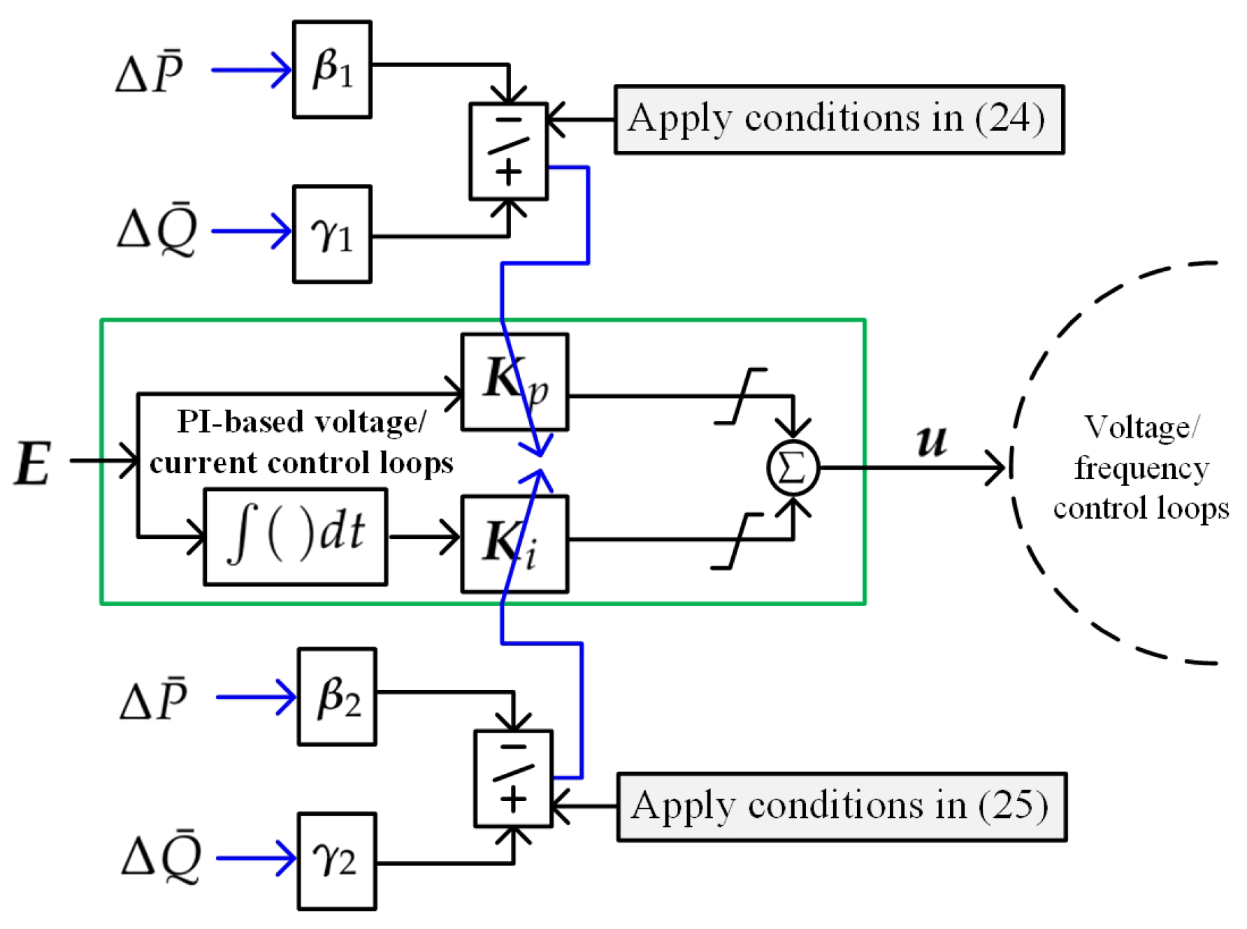
2.1. Proposed Grid-Forming Converter Control

In modern MG with high penetration of DERs, GFMs play a pivotal role in islanding MGs as it autonomously establishes and maintains grid-like conditions within isolated MG systems [3]. Its key advantages stem from its ability to facilitate seamless transitions between grid-connected and islanded modes, ensuring a consistent and dependable power supply. Furthermore, this converter significantly bolsters MG resilience through active control of voltage and frequency, enabling the efficient integration of renewable energy sources and DERs [4]. This capability ensures reliable power delivery, even when the main grid is unavailable. This subsection serves to introduce the system configuration and subsequently develops a comprehensive small-signal model. The small-signal model is deconstructed into distinct components, each introduced separately. Accordingly, these individual components amalgamate to form an overarching model.
Figure 1 shows the topology of GFM converter and its control strategies, where subscripts d and q represent the direct and quadrature axes, subscript g s c means belonging the the grid-side converter, subscript m g means belonging to the main grid or MG, superscript * implies the commanded signal, i is the current, V is the voltage, R is the resistance, L is the inductance, P and Q are the active and reactive powers, and α is the voltage phase angle. It should be noted that, in islanding mode, grid-forming converters do not typically rely on a phase-locked loop (known as PLL) since they operate independently to establish and control the voltage and frequency of the islanding grid [11]. As shown in Figure 1, voltage and frequency references (i.e., the outputs of PI-based voltage and current control loops) are generated by applying PI control to the output voltage and frequency of a GFM converter [22,23]. After that, these outputs are subtracted with i g s c , d q and V g s c , d q . This allows the converter to autonomously maintain stable voltage and frequency operation without the need for external grid references, making PLL unnecessary in grid-forming control. In this scenario, to use GFM converters to form the voltage and frequency of the islanding grid, the i g s c , d q and V g s c , d q are autonomously measured from the generators with the highest power supply capacity at that moment. Accordingly, this allows the islanding microgrid to have a black start capability.
From Figure 1, when viewed from a time-dependent perspective (denoted by variable t), we assume that the system evolves over time and is subject to reconfiguration. At jth operating condition (denoted by superscript [ j ] ), calculation of the active power (denoted as P) and reactive power (denoted as Q) of any kth distributed voltage source (VSC) GFM converter (denoted by superscript [ k ] ) transferred from the converter to the connected grid is as follows:
P k , j = 3 2 V d [ k , j ] i d [ k , j ] + V q [ k , j ] i q [ k , j ] ,
Q k , j = 3 2 V d [ k , j ] i q [ k , j ] V q [ k , j ] i d [ k , j ] .
The MG can be linearized at any jth operating point as shown below:
Δ x ˙ [ j ] = A [ j ] Δ x [ j ] + B [ j ] Δ u [ j ] , k ,
where Δ is the small deviation, x is the state vector, u is the input vector, A is the state matrix, B is the input matrix, and f x ( · ) is the non-linear equation representing overall MG’s dynamics.
In this paper, we employ a 5th-order model to represent an individual VSC GFM converter. Subsequently, we define x as:
x [ k , j ] = P [ k , j ] Q [ k , j ] i g s c , d [ k , j ] i g s c , q [ k , j ] V d c [ k , j ] ,
where superscript ⊤ represents the transpose of matrix and V d c is the dc-link voltage.
The differential equations of the variables in (4) are obtained by:
d P [ k , j ] d t = ω 0 [ k , j ] i g s c , d [ k , j ] V g s c , d [ k , j ] + i g s c , q [ k , j ] V g s c , q [ k , j ] ω 0 [ k , j ] P [ k , j ] ,
d Q [ k , j ] d t = ω 0 [ k , j ] i g s c , d [ k , j ] V g s c , q [ k , j ] i g s c , q [ k , j ] V g s c , d [ k , j ] ω 0 [ k , j ] Q [ k , j ] ,
d i g s c , d [ k , j ] d t = V g s c , d [ k , j ] R m g k i g s c , d [ k , j ] L m g k ,
d i g s c , q [ k , j ] d t = V g s c , q [ k , j ] R m g k i g s c , q [ k , j ] L m g k ,
d V d c [ k , j ] d t = i d c [ k , j ] C d c k V d c [ k , j ] V g s c [ k , j ] C d c k R m g k ,
where ω 0 = 2 π f 0 is the nominal angular frequency and f 0 is the expected frequency.

2.2. Structure of Robust-Adaptive Controller

The structure of the robust-adaptive controller is explained in this section. The relationship between the input and output of the proposed robust-adaptive controller (denoted as K ) for the kth distributed VSC GFM converter at the jth operating point can be expressed as follows when K p [ k , j ] , K i [ k , j ] K [ k , j ] :
u [ k , j ] = K [ k , j ] y [ k , j ] ,
where u is the input vector and y is the output vector.
The PI controller is frequently used in practical GFM control loops. In this context, we denote the input vector from PI controller as u . This notation applies to the following scenario: at any given kth distributed VSC GFM converter operating under the jth condition:
u [ k , j ] = K p k , j E k , j + K i k , j m j E k , j , m ,
where E is the error between the corresponding output and reference.
From Figure 1 and (11), E can be obtained by:
E [ k , j ] = r [ k , j ] y [ k , j ] .
Referring to Figure 1 and (12), we can express it as follows:
E 1 [ k , j ] E 2 [ k , j ] E 3 [ k , j ] E 4 [ k , j ] = V q [ * , k , j ] i q [ k , j ] · ω 0 [ k , j ] L m g k V q [ k , j ] i d [ k , l ] · ω 0 [ k , j ] L m g k V d [ k , j ] i g s c , d [ * , k , j ] i g s c , d [ k , j ] i g s c , q [ * , k , j ] i g s c , q [ k , j ] = Δ y 1 [ k , j ] Δ y 2 [ k , j ] Δ y 3 [ k , j ] Δ y 4 [ k , j ] .
Then, by incorporating (13), we can rewrite u as follows:
u 1 [ k , j ] u 2 [ k , j ] u 3 [ k , j ] u 4 [ k , j ] = K p , 1 [ k , j ] Δ y 1 [ k , j ] + K i , 1 [ k , j ] m j Δ y 1 [ k , j , m ] K p , 2 [ k , j ] Δ y 2 [ k , j ] + K i , 2 [ k , j ] m j Δ y 2 [ k , j , m ] K p , 1 [ k , j ] Δ y 3 [ k , j ] + K i , 3 [ k , j ] m j Δ y 3 [ k , j , m ] K p , 1 [ k , j ] Δ y 4 [ k , j ] + K i , 4 [ k , j ] m j Δ y 4 [ k , j , m ] .
In order to stabilize the frequency and voltage of MG under various conditions, we will design the parameters K p , 1 [ k , j ] K p , 4 [ k , j ] K p [ k , j ] and K i , 1 [ k , j ] K i , 4 [ k , j ] K i [ k , j ] . The next section provides a description of the proposed robust-adaptive controller designed for the PI voltage and frequency controllers of a GFM converter.

3. Proposed Robust-Adaptive Control Design

This section provides a detailed algorithm for designing a robust adaptive controller specifically tailored for GFM converters. Here, our objective is to minimize the cost function K while considering the system dynamics as outlined in (3). When striving to design a robust controller, the conventional approach entails defining the cost function [24]:
J = 0 ( x T W 1 x + u W 2 u ) d t ,
where W 1 and W 2 are the state and control input weighting factors, respectively.
Next, we need to find the optimal control input u that minimizes J . This is an infinite-time optimal control problem. We can use the calculus of variations to derive the necessary conditions for optimality. We introduced a Lagrange multiplier (denoted by λ ) to account for constraints (if any) and formed the Lagrangian, L :
L = 0 x T W 1 x + u W 2 u + λ T ( x ˙ A x B u ) d u .
To find the optimal u , we differentiate L with respect to u and set it equal to zero:
L u = 2 W 2 u B λ = 0 .
After that, solving for u , we have:
u = 1 2 W 2 1 B λ .
Substituting (18) back into (16) yields:
L = 0 x W 1 x + 1 4 λ T B W 2 1 B λ λ A x d t .
Next, we differentiate L with respect to λ and set it equal to zero:
L λ = 0 A x + B W 2 1 B λ d t = 0 .
This results in the equation:
A x = B W 2 1 B λ .
This equation is known as the algebraic Riccati equation and provides the optimal λ . In summary, the optimal control input u can be expressed as in (18). After that, the value of λ can be obtained by solving the algebraic Riccati equation. Once you have λ , you can compute the optimal control input u and the controller gains K p and K i to achieve the minimum cost J .
Given that the operating point of a MG often undergoes changes due to uncertain resources and DERs, and considering the presence of multiple VSC GFM converters, we take into account adaptive gains K p and K i through the following approach:
K p [ k , j ] = K p , [ k , j ] ± β 1 Δ P ¯ [ k , j ] ± γ 1 Δ Q ¯ [ k , j ] ,
K i [ k , j ] = K i , [ k , j ] ± β 2 Δ P ¯ [ k , j ] ± γ 2 Δ Q ¯ [ k , j ] ,
where β 1 and β 2 are, respectively, the robust-adaptive weighting factors of K p and K i considering the change in average active power deviation Δ P ¯ = b u s = 1 N b u s Δ P b u s N b u s , and γ 1 and γ 2 are respectively the robust-adaptive weighting factors of K p and K i considering the change in average reactive power deviation Δ Q ¯ = b u s = 1 N b u s Δ Q b u s N b u s .
In (22) and (23), we determined K p , [ k , j ] and K i , [ k , j ] through the linear matrix inequality as elaborated in (15)–(21). Simultaneously, the adaptive components β 1 Δ P ¯ [ k , j ] + γ 1 Δ Q ¯ [ k , j ] and β 2 Δ P ¯ [ k , j ] + γ 2 Δ Q ¯ [ k , j ] can be derived by monitoring the active and reactive power across the entire MG. The validation of the proposed robust-adaptive GFM controller will be presented in the following section. The following laws are applied to establish and define the terms β 1 Δ P ¯ [ k , j ] + γ 1 Δ Q ¯ [ k , j ] and β 2 Δ P ¯ [ k , j ] + γ 2 Δ Q ¯ [ k , j ] at ( j + 1 ) th operating point as:
K p [ k , j + 1 ] = K p , [ k , j ] + β 1 Δ P ¯ [ k , j ] + γ 1 Δ Q ¯ [ k , j ] , if Δ P ¯ [ k , j + 1 ] > Δ P ¯ [ k , j ] Δ Q ¯ [ k , j + 1 ] > Δ Q ¯ [ k , j ] K p , [ k , j ] β 1 Δ P ¯ [ k , j ] γ 1 Δ Q ¯ [ k , j ] , if Δ P ¯ [ k , j + 1 ] < Δ P ¯ [ k , j ] Δ Q ¯ [ k , j + 1 ] < Δ Q ¯ [ k , j ] K p , [ k , j ] , if Δ P ¯ [ k , j + 1 ] = Δ P ¯ [ k , j ] Δ Q ¯ [ k , j + 1 ] = Δ Q ¯ [ k , j ] , s . t . K p [ k , j + 1 ] K p min K p max ,
K i [ k , j + 1 ] = K i , [ k , j ] + β 2 Δ P ¯ [ k , j ] + γ 2 Δ Q ¯ [ k , j ] , if Δ P ¯ [ k , j + 1 ] > Δ P ¯ [ k , j ] Δ Q ¯ [ k , j + 1 ] > Δ Q ¯ [ k , j ] K p , [ k , j ] β 2 Δ P ¯ [ k , j ] γ 2 Δ Q ¯ [ k , j ] , if Δ P ¯ [ k , j + 1 ] < Δ P ¯ [ k , j ] Δ Q ¯ [ k , j + 1 ] < Δ Q ¯ [ k , j ] K p , [ k , j ] , if Δ P ¯ [ k , j + 1 ] = Δ P ¯ [ k , j ] Δ Q ¯ [ k , j + 1 ] = Δ Q ¯ [ k , j ] , s . t . K i [ k , j + 1 ] K i min K i max .
The innovative robust-adaptive GFM controller, as depicted in Figure 1, is characterized by its unique ability to incorporate adaptability directly into the PI controller of voltage and current control loops. Applying (24) and (25), Figure 2 illustrates the control diagram for the robust-adaptive PI controllers applied to GFM’s voltage and current control loops. This distinctive feature eliminates the necessity for additional controllers within the GFM converter control loops. As a result, the control system is simplified and the potential interactions between GFM control loops and those governing other converters are effectively minimized. This groundbreaking approach, which seamlessly integrates adaptability into the PI controller, not only simplifies the system but also significantly enhances the overall performance and robustness of the GFM control system while reducing its overall complexity. By eliminating the need for supplementary controllers, the GFM converter control system becomes more efficient and streamlined, leading to improved control system performance. This adaptation capability enables the controller to respond dynamically to changing conditions and requirements, making it a versatile solution for various applications. Moreover, this approach aligns with the principles of adaptive control, where the control parameters adjust automatically to optimize performance. The GFM converter control system can now better adapt to variations in load, voltage, or other operating conditions, ensuring stability and efficiency under a wide range of scenarios. This innovation represents a significant advancement in the field of converter control, offering a more robust and adaptable solution to meet the demands of modern power systems and electronic devices.

4. Simulation Results and Discussions

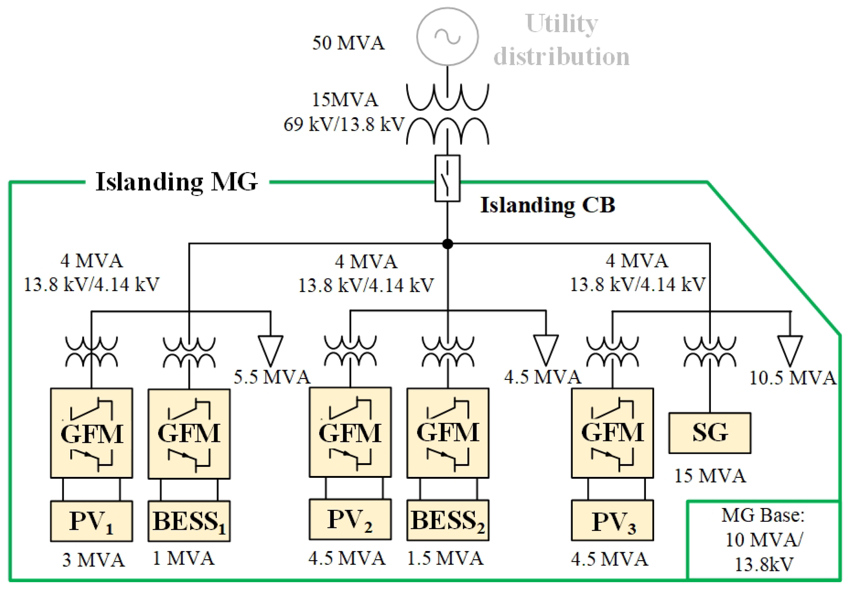
4.1. Modified Islanding MG with DERs

Figure 3 provides a comprehensive overview of the islanding MG configuration, as outlined in [25]. This MG, featuring a power base of 10 MVA and operating at 13.8 kV, interfaces with a 13.8-kV, 60-Hz distributed grid system via a circuit breaker. Notably, the MG has been subject to various enhancements, including the incorporation of three distributed solar photovoltaics (PVs) with individual capacities of 3 MVA, 4.5 MVA, and 4.5 MVA, respectively. Additionally, the system incorporates two distributed battery energy storage systems (BESSs) with capacities of 1 MVA and 1.5 MVA, along with a synchronous generator rated at 15 MVA. The cumulative load connected to the MG amounts to 20.5 MVA.
For efficient control and management, the PVs and BESSs are equipped with GFM converters, each tailored with specific control systems, as elaborated in Figure 3. It is important to note that while the utility distribution boasts a capacity of 50 MVA, it remains physically disconnected from the islanding MG during standard operational conditions.
The simulation and modeling of this intricate system have been meticulously carried out using the MATLAB and Simulink software package, ensuring a robust platform for analysis and optimization in the realms of DERs and MG operation.

4.2. Benchmark

In our endeavor to rigorously validate and comprehensively evaluate the performance of the newly introduced robust-adaptive GFM controllers, we undertook a multifaceted comparative analysis. This involved juxtaposing the proposed controllers with two distinct control scenarios: one without any controller and the other employing the conventional robust-adaptive GFL controller.
The design methodology utilized in developing the robust-adaptive GFL controller aligns with that employed for the proposed robust-adaptive GFM controller, thereby ensuring a direct and fair comparison. For detailed insights into the control topology governing the GFL converter, a comprehensive control strategy can be found in [26], thereby facilitating a precise examination of both control strategies within a unified framework.
In this paper, we designate the proposed robust-adaptive GFM controller as the “Proposed Robust-Adaptive GFM Controller”, while the absence of optimal control design is denoted as “Without Optimal Controller”, and the conventional GFL Controller is referred to as the “Conventional GFL Controller”. Following the optimization around the normal operating point, Table 1 displays the optimized parameters for the Proposed Robust-Adaptive GFM Controller within GFM’s voltage and current control loops. Please note that these parameters will undergo adjustments in accordance with the time domain, for instance, when t > 0 . This modification occurs when observing Δ P ¯ and Δ Q ¯ , as defined in Equations (24) and (25).

4.3. Numerical Results and Discussion

The Bode plots were employed to comprehend a system’s response to various frequencies, thereby facilitating the design, analysis, and troubleshooting of closed-loop systems. Figure 4 illustrates the Bode plot of the closed-loop system under three control strategies: without a controller, with the Conventional GFL Controller, and with the Proposed Robust-Adaptive GFM Controller, all evaluated at the standard operating point. It is evident that the system exhibits the highest gain when operating without a controller. The Conventional Robust-Adaptive GFL controller exhibits a lower gain, while the Proposed Robust-Adaptive GFM controller yields the lowest gain among the three scenarios.
Small-signal stability analysis is vital for examining the system’s response to minor disturbances and ensuring its resilience against variations in operating conditions. Here, we assessed the small-signal stability of the proposed method, a critical aspect, particularly in low-inertia MG conditions. This evaluation was conducted across various scenarios, including the standard or normal operating point, a condition with a substantial 30% increase in all loads, and an equally significant 30% increase in all generations, including both DERs and SG. These evaluations are represented in Figure 5.
As can be seen, there are three dominant modes presented in the system, namely, two MG local modes and two additional modes introduced by the controllers-GFM modes caused by the Proposed Robust-Adaptive GFM Controller and GFL modes generated by the Conventional Robust-Adaptive GFL Controller. Note that the dynamics of these modes vary in response to the changing operating conditions of the MG. These dynamic shifts in mode dominance highlight the adaptability and influence of the controllers, showcasing their ability to respond effectively to different MG operating scenarios. The results can be described as follows. At the normal operating point, the results reflect the Bode diagram, as described above (see Figure 4). In the same way, the loci of the Proposed Robust-Adaptive GFM Controller show slightly greater sensitivity compared to both the system without optimal controller and the Conventional Robust-Adaptive GFL Controller. This increased sensitivity is a key attribute that makes the Proposed Robust-Adaptive GFM Controller the most effective choice, especially when dealing with dynamic loading and generation changes.
Subsequently, we examined the loci of eigenvalues as the inertia of the MG was systematically reduced, ranging from 100% down to 50% with a 2% fixed step. This investigation, as depicted in Figure 6, examines how the system’s dynamic behavior evolves in response to decreasing levels of inertia when implementing the proposed method and compared strategies.
As can be observed, there are notable differences in the system’s behavior regarding sensitivity to changes in inertia. Specifically, without the optimal controller, there are two modes that exhibit high sensitivity to inertia changes. When utilizing the Conventional Robust-Adaptive GFL Controller, there is one such mode, and with the Proposed Robust-Adaptive GFM Controller, there is just a single mode showing high sensitivity.
Comparing these results to the conventional GFL converter control method, it becomes evident that the Proposed Robust-Adaptive GFM Controller stands out as being less sensitive to inertia variations. This reduced sensitivity makes the Proposed Robust-Adaptive GFM Controller a more robust and flexible choice when dealing with variations in system inertia. This advantage becomes particularly pronounced in low-inertia MG scenarios. In such cases, where inertia is limited, the Proposed Robust-Adaptive GFM Controller demonstrates superior performance compared to the conventional GFL converter control method, further underscoring its suitability for enhancing the stability and adaptability of the MG system.
To comprehensively assess the performance of the proposed method across a wide range of MG conditions, we conducted a thorough probability analysis involving 1000 random scenarios. In each of these scenarios, we introduced simultaneous random variations in all loads and generations, ranging from −30% to +30% of their normal operating points. Additionally, we varied the inertia within the range of 70% to 30%. Subsequently, we applied either the proposed GFM or conventional GFL controller to the MG with DERs and calculated the damping ratio (represented as λ ) for all dominant modes in each scenario. Furthermore, in order to provide a more comprehensive evaluation, we introduced an additional controller for comparison purposes. This controller, known as the Conventional Robust GFL Controller, was included to assess its performance alongside the previously mentioned strategies.
As a result, Figure 7 visually illustrates the probability distribution of λ resulting from these random events. This comprehensive analysis allows us to gauge the robustness and effectiveness of the proposed method under a wide spectrum of operating conditions, providing valuable insights into its performance and suitability for real-world MG applications. It is readily apparent that, among the compared methods, the Proposed Robust-Adaptive Controller consistently demonstrates superior damping characteristics.
This is evident as it consistently achieves damping values ranging from 15% to 23%, with the highest probability occurring at a damping value of approximately 21.23%. In contrast, when examining the performance of the compared controllers, it is worth nothing that some negative damping values occur in the case of the system operating without optimal controller. Furthermore, it is worth noting that the Conventional Robust GFL controller consistently yields slightly lower damping values, typically falling within the range of 5% to 17%, with the highest probability occurring at approximately 12.5%. On the other hand, the Conventional Robust-Adaptive GFL controller exhibits damping values within a similar range of 5% to 17%, but the highest probability occurs at around 15%. These comparative results underscore the distinct advantage of the Proposed Robust-Adaptive Controller in enhancing the stability and overall performance of the MG system across a wide spectrum of operating conditions. Its ability to consistently deliver high damping ratios showcases its effectiveness and reliability in effectively dampening oscillations and ensuring the secure and reliable operation of the MG.
Subsequently, a nonlinear simulation was conducted to assess the system’s response under dynamic conditions. In this simulation, all loads and generations were subjected to fluctuations ranging between −20% and +20% of their normal operating points, occurring at intervals of 2 to 5 s, where the simulation time is 50 s. Furthermore, the inertia was intentionally reduced to approximately 60% of the normal operating point to challenge the system’s stability.
After that voltage and frequency deviations are observed. As a result, Figure 8 visually illustrates the transient response of this case study. As anticipated, the Proposed Robust-Adaptive Controller outperformed the other controllers by providing the most robust and effective response against these disturbances in the time-domain simulation. This outcome reaffirms the controller’s capability to ensure the MG’s stability and performance, even under challenging and dynamic operating conditions.
To comprehensively evaluate the performance of the system under various dynamic scenarios, a time-domain simulation was repeated across 100 different scenarios when the boundaries of loads and generations were changed to −30% and +30% with a 15% fixed step. Accordingly, the simulation is demonstrated in Figure 9. During these simulations, data related to the rate of changes of voltage ( R o C o V ) and frequency ( R o C o F ) were collected. Subsequently, a probability analysis was conducted to validate and analyze these results. In a direct comparison between the Conventional Robust-Adaptive GFL Controller and the Proposed Robust-Adaptive GFM Controller, it is obvious that the latter leads to significantly reduced responses in terms of both R o C o V and R o C o F . This outcome underscores the substantial advantage of implementing the Proposed Robust-Adaptive GFM Controller in terms of voltage and frequency limitations.
This extensive analysis provides a comprehensive understanding of the system’s behavior under diverse operating conditions and disturbances. By examining the probability distribution of R o C o V and R o C o F it becomes possible to draw meaningful conclusions about the robustness and reliability of the Proposed Robust-Adaptive Controller. It reaffirms the controller’s efficacy in consistently maintaining stable voltage and frequency levels within the MG system across a wide spectrum of real-world scenarios, making it a highly valuable choice for MG applications.

5. Key Insights and Concluding Remarks

In this paper, the proposed robust-adaptive GFM converter control addresses the critical need for stability in MG operations with the increasing integration of renewable energy sources and DERs. By introducing innovative adaptive-robust controllers designed for GFM converters, it offers a versatile and effective solution for ensuring stable and reliable performance under diverse operating conditions within low-inertia MGs. The validation results underscore the controllers’ efficacy and potential to enhance MG resilience. The significant findings are summarized as follows:
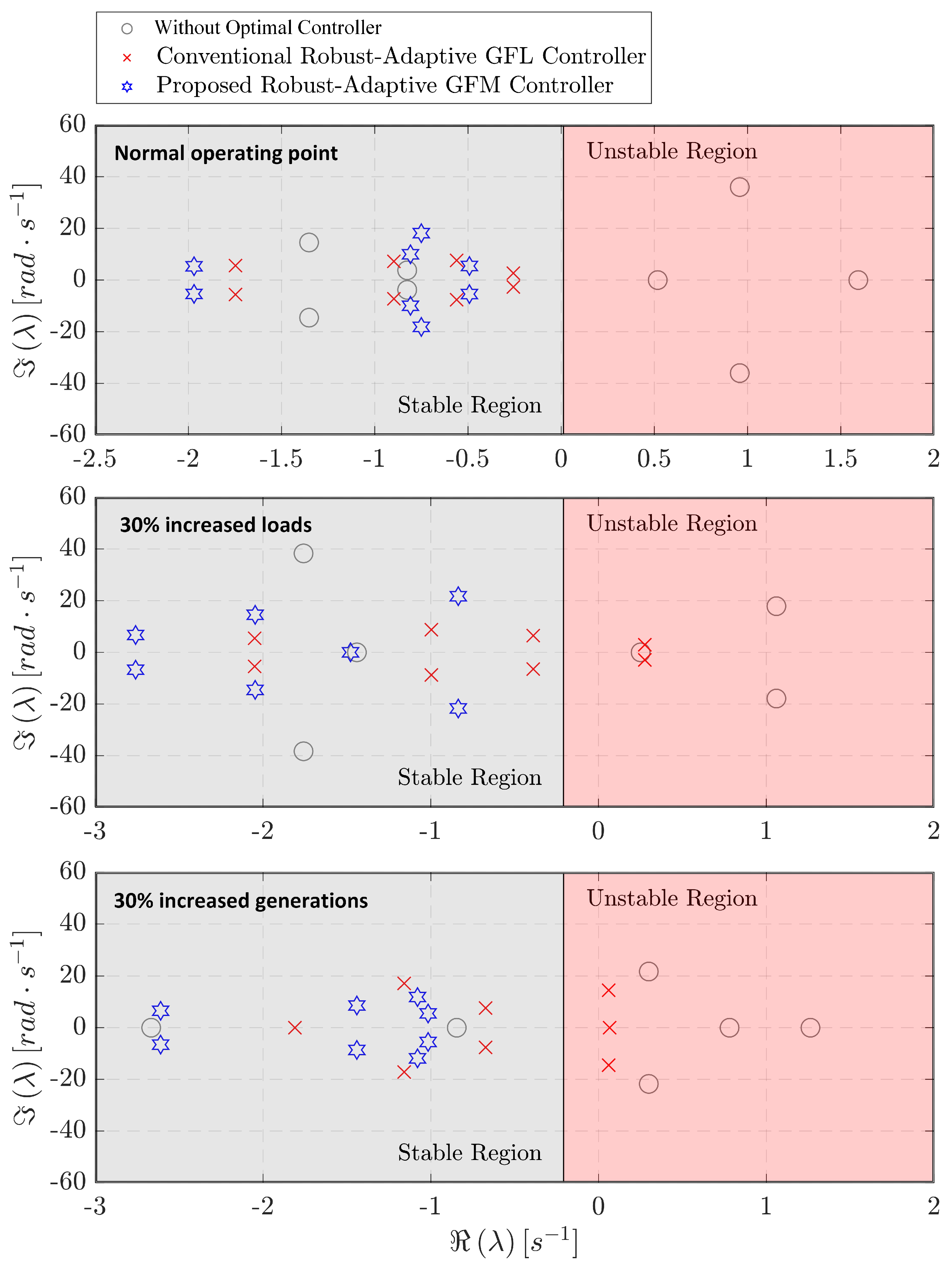
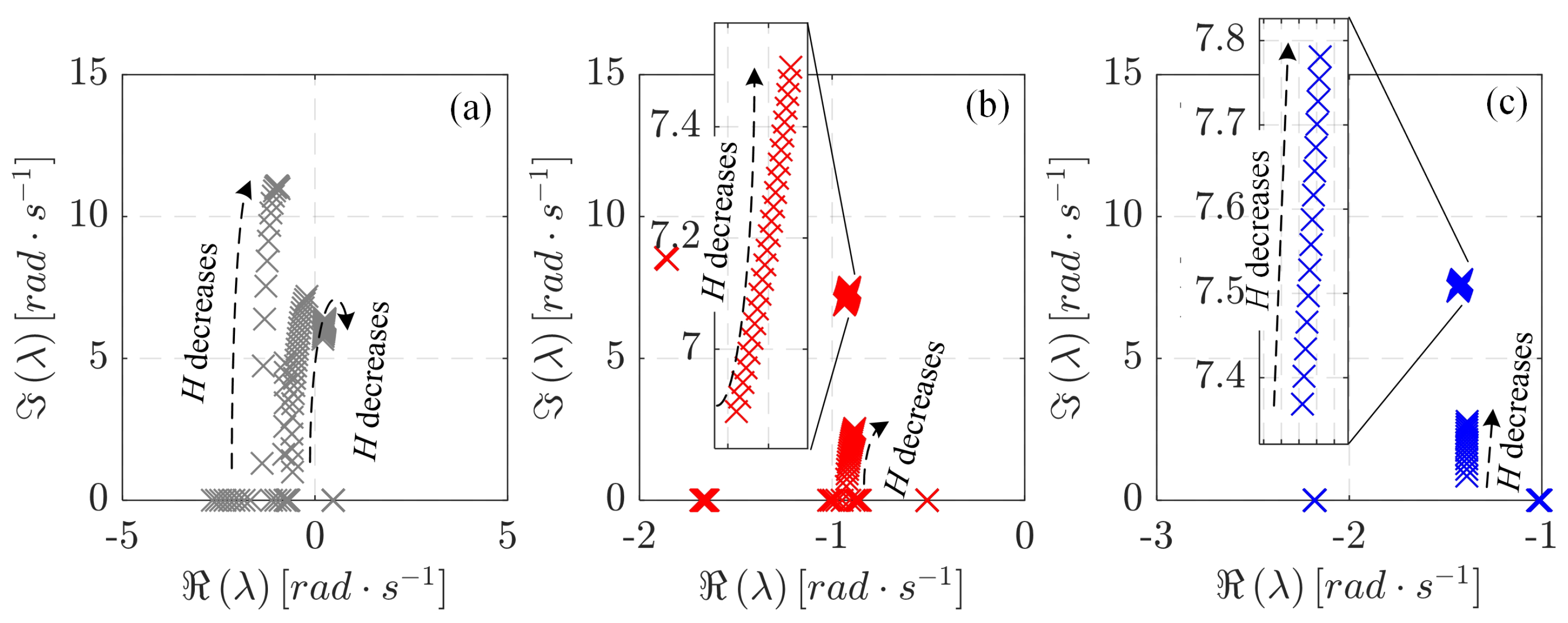
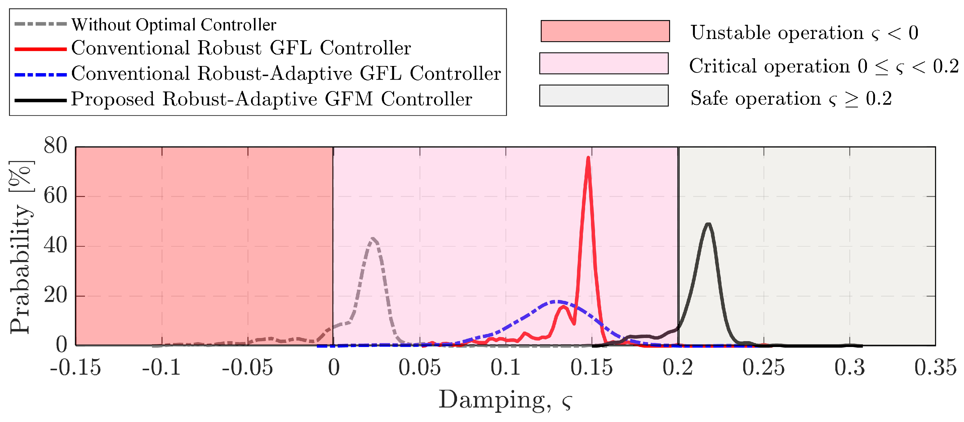
  • The Proposed Robust-Adaptive Controller consistently outperforms other controllers in terms of damping ratios, providing enhanced stability and performance across various operating conditions;
  • Through extensive time-domain simulations, it is evident that the Proposed Controller maintains superior performance when dealing with fluctuations in load, generation, voltage, and frequency, even in low-inertia scenarios;
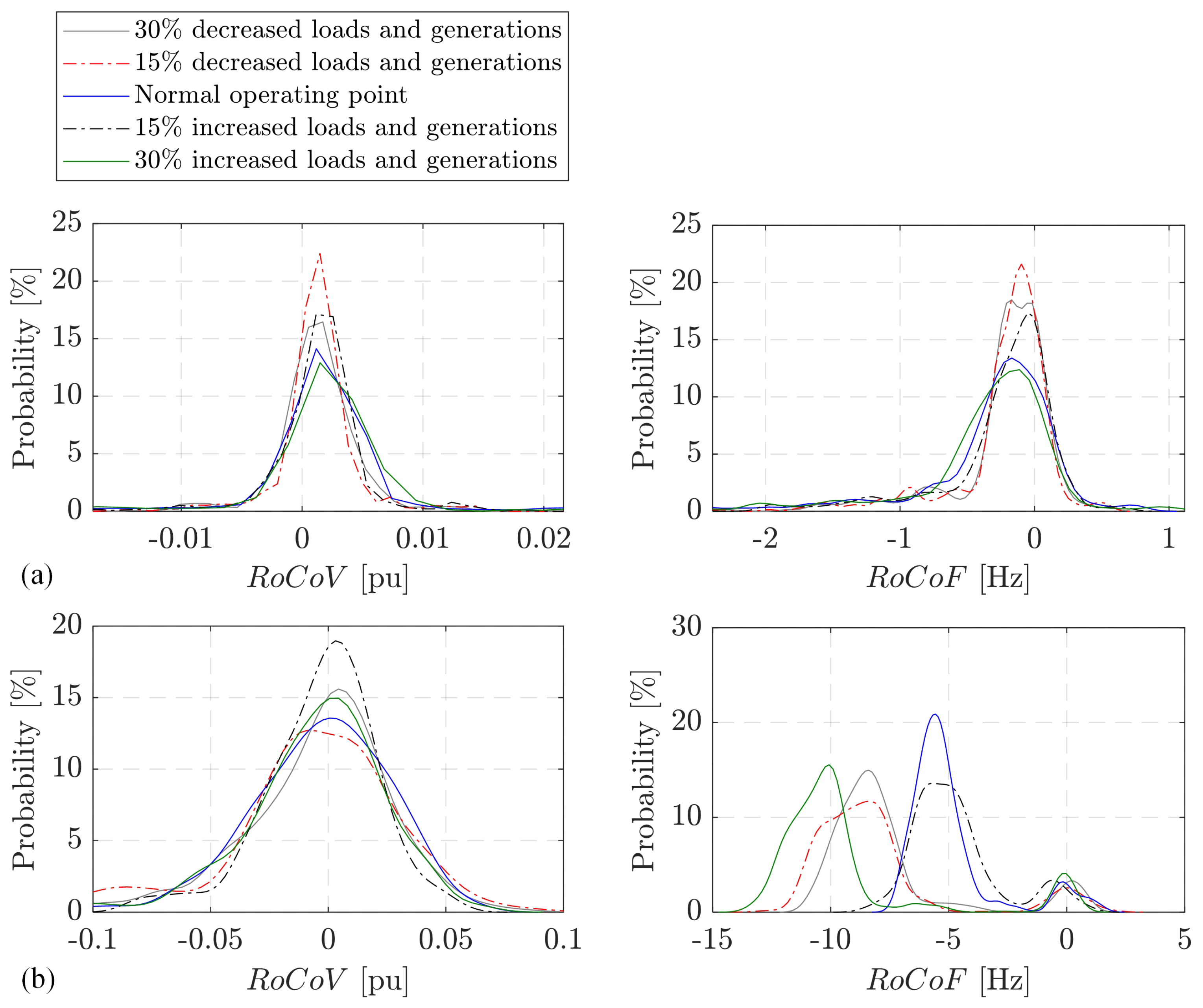
  • When compared to the Conventional Robust-Adaptive GFL Controller, the Proposed Robust-Adaptive GFM Controller demonstrates significantly reduced rate of changes in voltage ( R o C o V ) and frequency ( R o C o F ), indicating its superiority in ensuring stable MG operation;
  • The probability analysis further corroborates the robustness and reliability of the Proposed Controller, emphasizing its suitability for MG applications under a wide range of scenarios.
As there are certain limitations inherent to the proposed GFM control method, it is important to acknowledge these constraints while also capitalizing on the findings that have emerged from our extensive simulations. In light of this, our future research endeavors will be focused on refining and advancing the controller. Specifically, we will address the following key aspects:
  • Building upon the favorable outcomes observed in our simulations, we will strive to further enhance the performance of the Proposed Robust-Adaptive GFM Controller. This includes fine-tuning its parameters and algorithms to optimize damping ratios and response times;
  • We recognize the importance of exploring the controller’s adaptability to even more diverse and complex MG scenarios. Our aim is to ensure that it can effectively handle a broader range of disturbances and uncertainties;
  • To validate the practical applicability of our controller, we plan to conduct real-world experiments and field tests within actual MG systems using a real-time simulation with hardware-in-the-loop (known as HIL). This will help bridge the gap between simulation findings and real-world implementation;
  • We will continue to emphasize the robustness and reliability of the proposed controller, making it a viable and trustworthy choice for MG applications, even in challenging operational conditions;
  • We will explore the implementation of a central master controller to oversee the regulation of the GFM converter system.
By addressing these aspects in our future research, we aim to further refine and elevate the capabilities of the Proposed Robust-Adaptive GFM Controller, ultimately contributing to the advancement of MG control strategies.

Author Contributions

Conceptualization, W.P., P.K. and B.M.; methodology, W.P., P.K. and B.M.; software W.P.; validation, W.P., P.K. and B.M.; formal analysis, W.P., P.K. and B.M.; investigate W.P.; data curation, W.P.; visualization, W.P.; writing-original draft preparation, W.P.; writing-review and editing, W.P., P.K. and B.M.; supervision, B.M.; funding acquisition, B.M. All authors have read and agreed to the published version of the manuscript.

Funding

This research was funded by Suranaree University of Technology, Thailand (Research and Development Fund, Funding No.: IRD7-711-66-12-40).

Institutional Review Board Statement

Not applicable.

Informed Consent Statement

Not applicable.

Data Availability Statement

Not applicable.

Acknowledgments

This work was financially supported by the Suranaree University of Technology, Research and Development Fund, Thailand.

Conflicts of Interest

The authors declare no conflict of interest.

Abbreviations

The following abbreviations are used in this manuscript:
BESSBattery energy storage system
DERDistributed energy resource
DGDistributed Generation
MGMicrogrid
GFMGrid-forming converter
GFLGrid-following converter
PVPhotovoltaic
RESRenewable energy resource
R o C o F Rate of changes of frequency
R o C o V Rate of changes of voltage
SGSynchronous generator
VSCVoltage source converter

References

  1. Aboelezz, A.M.; Sedhom, B.E.; El-Saadawi, M.M.; Eladl, A.A.; Siano, P. State-of-the-art review on shipboard microgrids: Architecture, control, management, protection, and future perspectives. Smart Cities 2023, 6, 1435–1484. [Google Scholar] [CrossRef]
  2. Saeed, M.H.; Fangzong, W.; Kalwar, B.A.; Iqbal, S. A review on microgrids’ challenges & perspectives. IEEE Access 2021, 9, 166502–166517. [Google Scholar]
  3. Joshal, K.S.; Gupta, N. Microgrids with model predictive control: A critical review. Energies 2023, 16, 4851. [Google Scholar] [CrossRef]
  4. Ratnam, K.S.; Palanisamy, K.; Yang, G. Future low-inertia power systems: Requirements, issues, and solutions-A review. Renew. Sustain. Energy Rev. 2020, 124, 109773. [Google Scholar] [CrossRef]
  5. Sørensen, D.A.; Pombo, D.V.; Iglesias, E.T. Energy storage sizing for virtual inertia contribution based on ROCOF and local frequency dynamics. Energy Strategy Rev. 2023, 47, 101094. [Google Scholar] [CrossRef]
  6. Pinthurat, W.; Hredzak, B. Distributed control strategy of single-phase battery systems for compensation of unbalanced active powers in a three-phase four-wire microgrid. Energies 2021, 14, 8287. [Google Scholar] [CrossRef]
  7. Pinthurat, W.; Hredzak, B.; Konstantinou, G.; Fletcher, J. Techniques for compensation of unbalanced conditions in LV distribution networks with integrated renewable generation: An overview. Electr. Power Syst. Res. 2023, 214, 108932. [Google Scholar] [CrossRef]
  8. Shahzad, S.; Abbasi, M.A.; Ali, H.; Iqbal, M.; Munir, R.; Kilic, H. Possibilities, challenges, and future opportunities of microgrids: A review. Sustainability 2023, 15, 6366. [Google Scholar] [CrossRef]
  9. Shi, J.; Ma, L.; Li, C.; Liu, N.; Zhang, J. A comprehensive review of standards for distributed energy resource grid-integration and microgrid. Renew. Sustain. Energy Rev. 2022, 170, 112957. [Google Scholar] [CrossRef]
  10. Musca, R.; Vasile, A.; Zizzo, G. Grid-forming converters: A critical review of pilot projects and demonstrators. Renew. Sustain. Energy Rev. 2022, 165, 112551. [Google Scholar] [CrossRef]
  11. Teng, Y.; Deng, W.; Pei, W.; Li, Y.; Dingv, L.; Ye, H. Review on grid-forming converter control methods in high-proportion renewable energy power systems. Glob. Energy Interconnect. 2022, 5, 328–342. [Google Scholar] [CrossRef]
  12. Araujo, L.S.; Brandao, D.I. Self-adaptive control for grid-forming converter with smooth transition between microgrid operating modes. Int. J. Electr. Power Energy Syst. 2022, 135, 107479. [Google Scholar] [CrossRef]
  13. Qoria, T.; Gruson, F.; Colas, F.; Guillaud, X.; Debry, M.S.; Prevost, T. Tuning of cascaded controllers for robust grid-forming voltage source converter. In Proceedings of the 2018 Power Systems Computation Conference (PSCC), Dublin, Ireland, 11–15 June 2018; pp. 1–7. [Google Scholar]
  14. Rathnayake, D.B.; Akrami, M.; Phurailatpam, C.; Me, S.P.; Hadavi, S.; Jayasinghe, G.; Zabihi, S.; Bahrani, B. Grid forming inverter modeling, control, and applications. IEEE Access 2021, 9, 114781–114807. [Google Scholar] [CrossRef]
  15. Narula, A.; Bongiorno, M.; Beza, M.; Chen, P.; Karlsson, D. Coordinated control of grid-forming converters and hydro generators to enhance frequency quality of future power system. Electr. Power Syst. Res. 2022, 212, 108456. [Google Scholar] [CrossRef]
  16. Zuo, Y.; Yuan, Z.; Sossan, F.; Zecchino, A.; Cherkaoui, R.; Paolone, M. Performance assessment of grid-forming and grid-following converter-interfaced battery energy storage systems on frequency regulation in low-inertia power grids. Sustain. Energy Grids Netw. 2021, 27, 100496. [Google Scholar] [CrossRef]
  17. Li, Z.; Zang, C.; Zeng, P.; Yu, H.; Li, S.; Bian, J. Control of a grid-forming inverter based on sliding-mode and mixed H2/Hinf control. IEEE Trans. Ind. Electron. 2016, 64, 3862–3872. [Google Scholar] [CrossRef]
  18. Alcaide-Godinez, I.; Bai, F. Frequency support from multiple utility-scale grid-forming battery energy storage systems. In Proceedings of the 2022 IEEE/IAS Industrial and Commercial Power System Asia (I&CPS Asia), Chongqing, China, 7–9 July 2022; pp. 1271–1276. [Google Scholar]
  19. Lin, T.; Das, M.; Gole, A.; Isaacs, A. Adaptive fault ride through control of VSM Grid-forming converters. Electr. Power Syst. Res. 2023, 223, 109606. [Google Scholar] [CrossRef]
  20. Yu, J.; Liu, W.; Sun, J.; Zhang, F.; Yang, Y. An improved grid impedance estimator for grid-forming converters in consideration of controller dynamics. Int. J. Electr. Power Energy Syst. 2023, 154, 109424. [Google Scholar] [CrossRef]
  21. Liu, X.K.; Wang, Y.W.; Liu, Z.W.; Huang, Y. On the stability of distributed secondary control for DC microgrids with grid-forming and grid-feeding converters. Automatica 2023, 155, 111164. [Google Scholar] [CrossRef]
  22. Ngamroo, I.; Surinkaew, T. Control of distributed converter-based resources in a zero-inertia microgrid using robust deep learning neural network. IEEE Trans. Smart Grid 2023. [Google Scholar] [CrossRef]
  23. Surinkaew, T.; Emami, K.; Shah, R.; Islam, M.R.; Islam, S. Forced oscillation management in a microgrid with distributed converter-based resources using hierarchical deep-learning neural network. Electr. Power Syst. Res. 2023, 222, 109479. [Google Scholar] [CrossRef]
  24. Pal, B.; Chaudhuri, B. Robust Control in Power Systems; Springer: Berlin/Heidelberg, Germany, 2006. [Google Scholar]
  25. Ahn, S.J.; Park, J.W.; Chung, I.Y.; Moon, S.I.; Kang, S.H.; Nam, S.R. Power-sharing method of multiple distributed generators considering control modes and configurations of a microgrid. IEEE Trans. Power Deliv. 2010, 25, 2007–2016. [Google Scholar] [CrossRef]
  26. Awal, M.; Husain, I. Unified virtual oscillator control for grid-forming and grid-following converters. IEEE J. Emerg. Sel. Top. Power Electron. 2020, 9, 4573–4586. [Google Scholar] [CrossRef]
Figure 1. Overview of GFM converter control mainly consisting of power droops, virtual inductance loops, and voltage/frequency control loops. Note that the proposed robust-adaptive control design is applied to robustly adjust the control parameters in voltage and current control loops (see Section 3).
Smartcities 06 00132 g001
Figure 2. Diagram depicting the control system for the proposed robust-adaptive control.
Smartcities 06 00132 g002
Figure 3. Single-line diagram of the studied islanding MG with DERs.
Smartcities 06 00132 g003
Figure 4. Compared bode diagram between three different strategies.
Smartcities 06 00132 g004
Figure 5. Locations of dominant eigenvalues under different equilibrium points.
Smartcities 06 00132 g005
Figure 6. Eigenvalue loci when H decreases from 100 % to 50 % ; (a) Without Optimal Controller; (b) Conventional Robust-Adaptive GFL Controller; (c) Proposed Robust-Adaptive GFM Controller.
Smartcities 06 00132 g006
Figure 7. Damping of the dominant modes under various 1000 different scenarios of power outputs from DERs.
Smartcities 06 00132 g007
Figure 8. Transient responses of of Δ V and Δ F .
Smartcities 06 00132 g008
Figure 9. Probability of R o C o V and R o C o F under 100 different scenarios; (a) Proposed Robust-Adaptive GFM Controller; (b) Conventional Robust-Adaptive GFL Controller.
Smartcities 06 00132 g009
Table 1. Lists of control parameters for the proposed robust-adaptive PI controllers in GFM’s voltage and current control loops.
ParametersGFM of PV1GFM of BESS1GFM of PV2GFM of BESS2GFM of PV3
Voltage control loop β 1 0.335153290.0944453860.2713257360.1474743770.385127392
γ 1 0.0263045230.0582866780.0520112190.0368704510.051688293
β 2 0.6629447370.5253973630.6264718490.5556996440.691501367
γ 2 0.273374391.1528836430.9803085160.5639374110.971428063
K p , 7.4180552447.5905136617.4160841764.5769223877.711214672
K i , 2.7678375898.1830509793.7839001592.846285434.8782461
Current control loop β 1 0.3670271780.369681550.0841391420.2414085320.387710987
γ 1 0.0588237110.0394150260.0256754540.0566294210.058379697
β 2 0.6811583870.6826751710.5195080810.6093763040.692977707
γ 2 1.167652060.6339132140.2560749721.1073090781.155441669
K p , 8.8684697948.0734935117.795345663.2284883599.626665366
K i , 9.5049493585.4417026472.7387463488.6759337122.758345604
Disclaimer/Publisher’s Note: The statements, opinions and data contained in all publications are solely those of the individual author(s) and contributor(s) and not of MDPI and/or the editor(s). MDPI and/or the editor(s) disclaim responsibility for any injury to people or property resulting from any ideas, methods, instructions or products referred to in the content.

