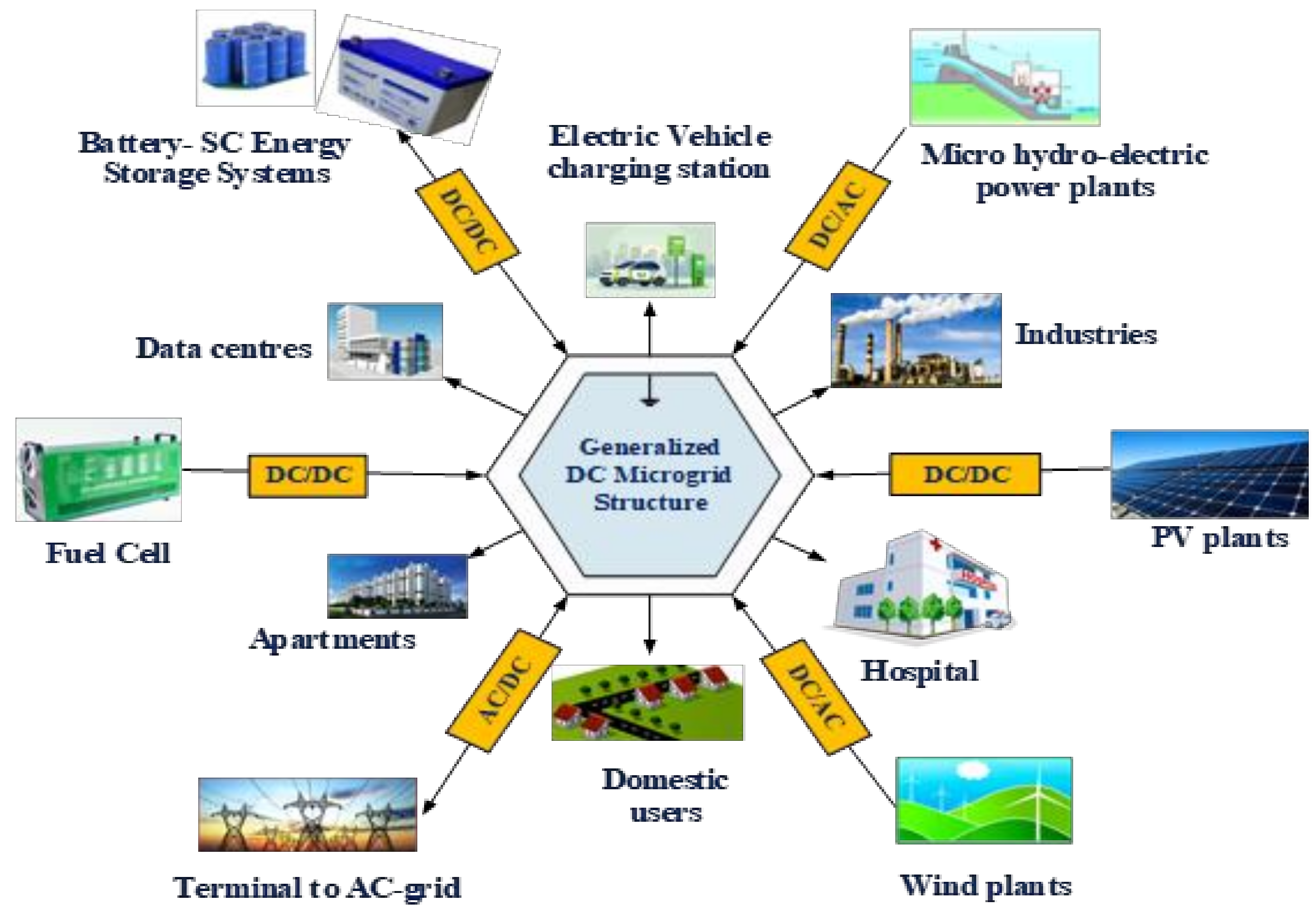
Article

Design, Analysis and Implementation of Bidirectional DC–DC Converters for HESS in DC Microgrid Applications

by
Srinivas Punna
1,
Rupesh Mailugundla
1 and
Surender Reddy Salkuti
2,*
1
Department of Electrical and Electronics Engineering, BVRIT Hyderabad College of Engineering for Women, Hyderabad 500090, India
2
Department of Railroad and Electrical Engineering, Woosong University, Daejeon 34606, Korea
*
Author to whom correspondence should be addressed.
Smart Cities 2022, 5(2), 433-454; https://doi.org/10.3390/smartcities5020024
Submission received: 28 February 2022 / Revised: 25 March 2022 / Accepted: 25 March 2022 / Published: 28 March 2022
(This article belongs to the Special Issue Feature Papers in Section Smart Grids)

Abstract

:
This research proposes an enhanced converter for a hybrid energy storage system (HESS) for a multi-input bidirectional DC–DC power converter (MIPC). When batteries are used for energy storage, their charge and discharge rates are low, putting the battery under current stress and shortening its life. Because of their increased power density, supercapacitors (SCs) can react quickly to abrupt fluctuations and solve this problem. SCs, on the other hand, cannot be utilized for storage since they cannot provide power for prolonged periods of time. Batteries and supercapacitors are employed together in HESSs because their opposing characteristics make them an ideal pair for energy storage. An MIPC is used to connect the HESS to the DC microgrid. The MIPC allows for decoupled battery and SC power regulation, as well as energy transfer across storage devices inside the system. A controller has been developed to regulate both HESS charging and discharging operations, making it a unified controller for DC microgrid applications. The proposed model predictive control (MPC) provided better DC grid voltage restoration to step change in PV generation and load demand over the traditional proportional integral (PI) control scheme. The MPC method minimizes current strains, extends battery life and enhances overall system performance in response to a step change in PV power and load demand as well as providing quicker DC grid voltage control. Simulation and experimental data for the proposed controller were created by varying PV generation and load demand, resulting in faster DC link voltage regulation.

1. Introduction

Generally, alternative sources of energy are preferred to supply a certain portion of the world’s power demand, based on their availability and lower impact [1]. As per the best renewable energy source (RES), solar power generation stays most relevant. Individual power generators depend on heavily on energy storage systems (ESSs), and the grouping of a battery and an SC can deliver an outstanding performance that can shield a broad collection of power and energy supplies from RESs, such as wind and PV generation [2]. The important functions of ESSs concern conservation, energy density, lifespan, power density and cost [3]. Normally, deep cycles and unbalanced charging patterns occur in a battery due to the fluctuating of PV output and non-linear and heavy power load. In a battery, these processes can reduce the life and raise the restoration cost [4]. The technical characteristics such as power, response time, energy and durability are balancing factors for the battery’s performance, and an SC is very important for good performance.
The HESS is classified according to the procedure of power conversion in its structures into two types: passive or active [5]. For combining the storage device and the DC link, the active technique employs one or more DC/DC converters [6]. A HESS must have a power conditioning component as well as an energy management strategy (EMS). If DC/DC converters are used in HESS, multi-input converters (MICs) should be used to produce the most cost-effective, easy-to-access, and intelligent ESS settings [7]. When the circuit topology is simple and the unified control of the storage component power flow is bidirectional, there is high consistency and the production cost and size are low; such converters have been proven to have greater responsiveness. Managing the power flow of the SC with a battery based on the controller approach is necessary for HESS for improving the consumption and capability [8].
Various controller techniques, such as artificial intelligence (AI), and technologies such as fuzzy logic control (FLC), artificial neural networks (ANNs) and genetic algorithms (GAs), are being used for HESS [9]. Based on the above control approaches, the battery assists in achieving a low power factor and SC assists in a high power factor [10]. For developing the battery efficiency, the minimization of the battery’s maximum current will reduce the inner voltage drop. Reducing the heating and inner losses of the storage system will reduce the battery’s dynamic stress. In this paper, we propose an enhanced controller for an MIPC. The enhanced controller is specified as the MPC controller, which is utilized for current and voltage control loops. The MIPC model is designed with the PV system and the controller is developed and also the HESS is considered to have a battery and an SC.
Figure 1 depicts a typical DC microgrid design. In most cases, the PV panel generates DC electricity. Wind turbines, on the other hand, create alternating current (AC). Because there are various renewable energy sources, power electronics such as AC–DC converters and DC–DC converters are used to link DC networks. The power converters allow flexibility and control over the power output of the RESs.
ESSs are necessary in the system because of a power imbalance between demand and supply. Combining multiple ESSs has been increasingly common in recent years, since it offers more benefits than a single ESS. Hybrid energy storage systems (HESSs) integrate the actions of several energy storage components to increase the system’s stability.
DC microgrids can operate in one of two modes: freestanding or grid connected. Local loads are controlled via RES generation and a HESS in standalone mode. The power flow between the DC microgrid and the AC microgrid in grid-connected mode allows greater flexibility and control over power output from the RESs and HESSs. The power balance in the system, on the other hand, is determined by the system’s stability. The authors of [11] provide a comprehensive overview of the control mechanisms and energy management strategies for AC and DC microgrids. The major necessity during PV generation and load demand volatility is to control the grid voltage as rapidly as feasible. To balance the grid utilizing RESs and HESSs, effective power sharing mechanisms are necessary. Different types of bidirectional converters and control strategies for HESSs in DC microgrid systems are discussed in this research. The suggested control methods are intended for DC grid voltage adjustment, battery charge/discharge rate control and battery and SC power splitting.
The paper is organized as follows: Some recent literature about HESS is presented in Section 2. The detailed investigation of the MIPC approach is defined in Section 3. The control system scheme is explained in Section 4. Then, simulated and experimental results of the proposed structure are examined in Section 5 and Section 6. The final part of this paper is a summary the proposed technique and its performance, in Section 7.

2. Recent Research Works: A Brief Review

In the literature, there has been a lot of research on successfully preserving the battery in a HESS by applying SCs. Some of these works are reviewed here.
Karthikeyan et al. [12] investigated a multiple input configuration of an isolated, bidirectional, dual-active bridge DC–DC converter (MIBDC) for managing the power flow in grouping the battery-driven storage. On the multi-input side, that arrangement could be also utilized with an inadequate level of voltage origins by combining them in series. A smart energy management algorithm (SEMA) for HESS rendered from three-phase and four-wire grid–related PV power generation systems was implemented by Aktas et al. [13]. The HESS comprising a battery and ultra-capacitor (UC) was tested for the possibility of use with a solar PV power generation method.
An ESS with a bidirectional DC–DC converter (BDC) for resolving a problem connected with the switching mode was presented by Kwon et al. [14]. The ESS accomplished small- or extended-term energy shielding as required for energy management while also rendering excellence electrical energy conductivity in DC microgrid (MG) schemes. The microgrid was programmed to activate islanded and grid integrated modes together. A BDC was associated with the energy storage, and a DC bus of dissimilar voltage moments in hybrid electric vehicle structures was developed by Ching-Ming et al. [15]. The converter could function in step-up and step-down modes, both with bidirectional power flow control. Moreover, the design could individually regulate the power flow between two low-voltage sources.
An expansible multi-input step-up DC–DC converter (MISUC) structure capable of handling several RESs, providing a modified output response with a normal load, was presented by Deihimi et al. [16]. Their layout offered advanced voltage improvements by growing the number of inputs in a way designed for a comprehensive collection of presentations in the HESS. The input sources were measured concurrently to give the desired load by regulating the output voltage at the preferred stage.
The use of a PI controller for HESS has drawbacks such as difficulty in tuning the controller parameters and the requirement for additional filters to share the high- and low-frequency power fluctuations [17,18,19,20,21]. This work proposes comparative analysis of traditional PI over an MPC-based method to control the MIPC for HESS in DC microgrid applications. The MPC is a cutting-edge approach that uses a discrete model of the system and the current state of the system to forecast future states and choose the best control action to take at each sampling moment. A MPC control strategy for a multiple-input bidirectional DC–DC converter of HESS is suggested in this study for DC grid voltage adjustment, battery charge–discharge rate control and power sharing between the battery and SC. The following are the goals of the proposed project:
  • less computational complexity,
  • simple double-loop control structure with an outside voltage loop that generates dynamic references and an inner current control loop that splits the references without using low-pass filters and tracks them using MPC principles, and
  • better dynamic performance and reduction in DC grid voltage variation compared to the conventional PI control method.

3. HESS-Supported RES Configuration

Figure 2 depicts the design of the HESS-assisted RES’s two-input bidirectional converter setup that is described in this section. It comprises a PV and HESS off-grid RES with a battery–supercapacitor bank configuration. PV generation is one of the most essential RESs for the DC microgrid. A boost converter is used to get the most power out of the PV panels and to connect to the DC microgrid. The HESS is made up of a battery and an SC bank, and it reacts swiftly to provide rapid DC grid voltage regulation in the case of a mismatch between PV generation and load demand.
The many methods of operation are detailed in [22]. The operation of a modified converter is described here. It is made up of three legs that switch. Legs 2 and 3 are linked to the battery (VB) and supercapacitor (VS) modules, respectively. Leg 1 is linked to a DC microgrid (VDC). The battery voltage is larger than the SC voltage and less than DC grid voltage in this converter design. Legs 1, 2 and 3 are linked to the high-frequency inductors LB and LS, respectively. The sections that follow explain the various modes of functioning.

3.1. Power Transfer from HESS to the DC Grid

The switching pattern for power semiconductor devices operates in different time periods as shown in Table 1. The duty cycle, dS, was applied to the switches, S5 and S2, and the complementary duty cycle, dS, was applied to the switches S6 and S1. The duty cycle, dB, was applied to the switch S3, and the complementary duty cycle, dB, was controlled by S4.
The DC microgrid power deviates from steady state when there is a power imbalance between PV generation and load demand. Due to reduced solar irradiance or increase in load demand, the DC grid voltage tends to drop. In order to balance the DC grid power, power flow from the battery–SC-based HESS to the DC microgrid occurs as represented in Figure 3a–c. At time instant t = to, the switching devices S2, S3 and S5 are turned on. As a result, the inductor currents iB and is increase linearly with a slope of VB/LB and VS/LS. At time instant t = t1, the switch S3 is turned off to allow a freewheeling path for the battery current as shown in Figure 3b. After the dead band time period of the switches S3/S4, the switch S4 is turned on. At time instant t = t2, switches S2 and S5 are turned off, the SC current flows through the body diodes with a negative slope of VDC/LS. The battery current iB flows through body diode of switch S1 with a negative slope of VDC/LB as shown in Figure 3c. At time instant t = t3, switches S1, S4 and S6 are turned off. As a result, in order to maintain the inductor current flow, the S2, S3 and S5 body diodes begin conducting. The inductor currents iB and iS flow with positive slopes of VB/LB and VS/LS. After a dead time period, switching pulses are delivered to switches S2, S3 and S5. Switch S3 has a duty ratio of dB, while switches S2 and S5 have duty ratios of dS.
The dB will always be smaller than the dS since the battery voltage VB is larger than the SC voltage VS. Controlling dB and dS individually allows regulation of the power flow between the battery and the SC and the DC microgrid.

3.2. Power Transfer from DC Grid to HESS

Excess power exists in the DC microgrid if the PV-produced power exceeds that required by the load or when load demand falls, resulting in an increase in DC grid voltage. Extra power generated by the PV panel will be stored in the battery and SC. As a result, electricity flows from the DC microgrid to the HESS in this situation. In this manner, the functioning of the converter employing equivalent circuits may be illustrated in three switching time periods, as shown in Figure 4a–d. Table 2 lists the operating switches for each time interval.
Table 3 depicts the relationship between the DC grid voltage to the battery and SC after inductors LB and LS have been volt-second balanced.
Switches S1, S4 and S6 are activated at time t0 to raise inductor currents iB and iS with a negative slope of VDC/LB and VDC/LS, respectively. Inductors store energy between the times t0 and t1. Switches S1 and S6 are switched off at time t1. To keep the inductor current iS constant, the body diodes of S2 and S5 are switched on. The energy stored in the inductor LS will now be used to charge the supercapacitor. The inductor current iB freewheels via switch S2’s body diode. Switch S4 is turned off at time instant t2. With a slope of VS/LS, inductor current iS passes through the body diode of switch S3. The energy stored in the inductor LB is now used to charge the battery. Switches S2, S3 and S5 are switched off at time t3, while the body diodes of switches S1, S4 and S6 are turned on to preserve inductor current flow. The ratio of SC and battery voltage to DC grid voltage is maintained by volt-second balancing the inductors LB and LS, as indicated in Table 3, where dB is the duty cycle of switch S4 and dS is the duty cycle of switches S1 and S6.

3.3. Power Transfer from Battery Bank to SC (Energy Exchange Mode)

Although a supercapacitor has a high power density, it cannot provide continuous power similar to a battery. It is necessary to charge the supercapacitor using the battery in order for the HESS to work properly. Power is transferred from the battery to the supercapacitor in this mode. Figure 5 shows the equivalent electrical circuit and steady-state waveforms of energy exchange mode operation.
By opening switches S1 and S2, the DC microgrid is disconnected from the HESS in the energy exchange mode; S3/S4 and S5/S6 are complimentary switching pairs in this mode. In this state, switch S5 is entirely on, causing switch S6 to be completely open circuited, as seen in Figure 5. Switch S3 has a duty cycle of d, and switch S5 is turned on entirely to allow power to flow from the battery to the supercapacitor, as in a buck operation. To eliminate current ripple, the two inductors are linked in series. The power flow from the battery to the supercapacitor may be regulated by adjusting the duty cycle, d. Figure 5 depicts the converter switching procedure for SC charging/discharging. Table 3 shows the relationship between battery voltage and SC voltage when volt-second balancing is applied to equivalent inductance Leq (Leq = LB + LS).

4. PI Control System Scheme of HESS

Figure 6 shows a control system block diagram depiction of the PI control strategy. The PI control technique will result in a controller that not only performs well in a closed loop but also remains stable in the face of converter dynamics and external disturbances. In this procedure, the nominal DC link voltage (VDC) is compared to a reference voltage (VDC,ref), and the error is sent to the PI controller, which generates the total current (itot) from the ESS. In the PI control method, total current is divided into low-frequency (ILOW) and high-frequency (IHIGH) components, which are subsequently given as reference currents to the battery and supercapacitor loops, respectively, as illustrated in Figure 6. The SC current reference has a high-frequency component, while the battery current reference has a low-frequency component in the PI control system.

4.1. PI Controller Design for HESS

The control system block diagram, as shown in Figure 7, is made up of an inner SC current loop and an outside voltage loop (Figure 7a). Figure 7b depicts the battery current reference block diagram. The bandwidth of the SC current control loop is greater than that of the battery current control loop for rapid response. In comparison to the outside voltage loop, the inner SC current loop functions quicker. As a result, the current loop bandwidth is preserved more than the voltage loop bandwidth. In this work, the switching frequency was set at 10 kHz.

4.1.1. SC Current Control Loop Design

Table 4 shows the small signal transfer functions estimated for the control parameters of the SC control loop. VDC stands for DC grid voltage, iB for battery current, iSC for SC current, dB for battery current controller duty cycle and dSC for SC current controller duty cycle in Table 4. To calculate current-compensated parameters, the open-loop transfer function G i SC d SC was employed. The proportional and integral gains for the SC current controller are shown in Table 4 as K p . SC and K i , SC . The SC inner current control PI controller settings were acquired by using a bandwidth of 1.6 kHz and a phase margin of 60°. The SC current-compensated parameters estimated using the MATLAB SISO toolbox were K p . SC = 0.4124 and K i , SC   = 2291.
The open-loop and closed-loop transfer functions for the SC current control loop were computed to determine the system’s stability.
G ol _ SC = G pi , sc . G i SC d SC   H SC
G cl _ SC = G pi , sc . G i SC d SC   1 + G pi , sc . G i SC d SC   H SC
where G ol _ SC denotes an open-loop transfer function, G cl _ SC denotes a closed-loop transfer function and H SC   denotes the SC current control loop’s feedback gain. Figure 8 depicts the corrected and uncompensated Bode charts for an open-loop SC current control loop. The Bode plot demonstrates that the supplied controller was stable for a certain phase margin and gain margin.

4.1.2. Design of Battery Current Control Loop

Table 4 shows the modest signal transfer functions for the battery current control loop. To determine control gains, the open-loop transfer function of battery control G i B d B was employed. K p , b and K i , b are the proportional and integral gains for the battery control loop, respectively, in Table 4. With a phase margin of 59.2° and a bandwidth of 1 kHz, the battery controller gains were computed. The control parameters K p , b = 1.971 and K i , b = 7300 were determined using the MATLAB SISO toolbox.
G ol _ B = G pi , B .   G i B d B . H B
G cl _ B = G pi , B . G i B d B 1 + G pi , B . G i B d B . H B
where G ol _ B denotes the open-loop transfer function and H B is the battery control loop’s feedback gain. Figure 9 shows the compensated and uncompensated Bode graphs for open-loop transfer functions. For a particular phase margin and gain margin, the Bode plot reveals that the intended control was stable.

4.1.3. Overall Outer Voltage Control Loop

The voltage control loop design requires battery- and SC-current-adjusted data. The outer voltage control loop had a bandwidth of 200 Hz and a phase margin of 60 degrees. The proportional and integral gains for the outer voltage loop were K p , v   = 0.5054 and K i , v = 266. The open-loop transfer function of the outer voltage control loop was determined as follows.
G ol _ v DC = G pi , v . G cl _ SC . Gvi SC . H V
G ol _ v DC was used to calculate the system’s stability, where H V denotes the voltage control loop’s feedback gain. Figure 10 depicts the open-loop transfer function of a voltage control system for corrected and uncompensated Bode plots. The Bode plot illustrates that the system as stable for the specified operating point for the requisite phase margin and gain margin.

4.2. MPC Control Strategy

The control structure incorporated two levels of control to regulate DC grid voltage stabilization: outer voltage control and inner current control. The outer voltage control loop’s job was to calculate the HESS’ dynamic reference current for DC grid voltage regulation. The power management algorithm divided the reference current, resulting in a lower battery depletion rate and a better power balance between load and PV generation. The production of modeling signals and the prediction of battery and SC inductor currents was based on a discrete DC–DC converter model that provided the least error between predicted and reference values. Figure 11 shows a block diagram illustration of the MPC control mechanism.

4.2.1. Outer Voltage Control Loop

The current through the DC link capacitor is given by the following formula, and the charging current i c is directly affected by the DC grid voltage variation.
i c = C dV dc dt
The above equation can be enlarged with a short sample time using Euler’s difference law.
i c k = C × V dc k V dc k 1 T s
Ts stands for the sampling time, V dc k for the current sampling DC grid voltage and V dc k 1   for the prior sampled DC grid voltage.
i c k + 1 = C × V dc k + 1 V dc k T s
In order for V dc k + 1   to be V ref , the i c k + 1 value calculated from the preceding equation would be big at first. To restrict this value, an integer coefficient N as a prediction horizon was inserted.
i c k + 1 = C × V ref V dc k N T s
For DC grid voltage control, the total reference current to be delivered by the HESS is given by
i ref k + 1 = i c k + 1 + i dc k
where i dc k is the total load current.

4.2.2. Inner Current Control

An averaged voltage balancing equation across these inductors was created for Lb to forecast battery and SC inductor currents.
L b di b dt =   V b d b   V dc 1 d b
By using Euler’s difference law
L b i b k + 1 i b k T s =   V b k d b i   V dc k 1 d b i
The above equation i b k + 1 was calculated
i b k + 1 = T s L b × [ V b k d b i   V dc k 1 d b i ] + i b k
Similarly, the inductor current SC model was derived as follows
L sc di sc dt =   V sc d sc   V dc 1 d sc
From the above equation i sc k + 1 is derived as
i sc k + 1 = T s L sc × [ V sc k d sc i   V dc k 1 d b i ] + i sc k
The cost functions for battery and SC current control are
  J b = ( i bref i b k + 1 2
J SC = ( i SCref i SC k + 1 2
Using the i b k + 1 and i SC k + 1 equations, duty cycles db and dsc were computed sequentially from 0 to 1 with a 0.01 increment, and each value was compared to ibref and i SCref during each sampling interval, and the duty cycle with the lowest cost function value was chosen.

5. Simulation Results and Discussion

This section details the findings of the suggested system, which comprises the MIPC, PI and MPC controllers, as well as the battery, SC and DC supply. The suggested setup is based on MATLAB/Simulink 7.10.0 (R2021b, Torrance, CA, USA) with an Intel (R) Core (TM) i5 CPU and 8 GB of RAM. The Simulink model for the suggested system was developed, showing the proposed system with the PI and MPC controller for regulating the MIPC’s switching signal. The proposed method maintained a consistent DC link voltage regardless of variations. To stabilize the DC link voltages, the MIPC was regulated by the recommended controller.
The nominal parameters for simulation study is provided in Table 5.

5.1. PI Control System Results in a Step Change in PV Generation

Figure 12 shows the simulation results for a step change in PV generation using a PI control system. The PV panel’s power output varied from 96 to 192 W at t = 0.2 s and then returned to 96 W at t = 0.4 s due to atmospheric fluctuation. PV current increased from 3 to 6 A in 0.2 s and then returned to 3 A in 0.4 s. The load power demand was 96 W in this situation. When PV output exceeded demand power by 96 W at t = 0.2 s, the DC grid voltage rose to greater than 48 V. The SC absorbed 96 W of surplus power in a short period of time until the battery could control the DC grid voltage to 48 V. To keep the DC grid voltage constant at 48 V, the battery and SC were charged according to an energy management plan. According to the obtained data, the settling time was 110 ms for a step increase in PV generation at t = 0.2 s and 120 ms for a step reduction in PV generation at t = 0.4 s.

5.2. Step Change in Load Demand Using PI Control Scheme

Figure 13 shows the simulation results for a step change in load demand. The load power requirement grew from 96 to 192 W at time t = 0.2 s. The load current increased from 2 to 4 A as a result of this. PV current was constant at 3 A in this condition. When the load power climbed to 192 W at t = 0.2 s, the PV power generating range was exceeded.
As a result, there was a power imbalance between the supply and the load. In this situation, the DC grid voltage will be affected by unexpected load variations. To handle the extra power in a DC microgrid, the HESS reacts quickly to these unexpected load variations. The SC is in charge of high-frequency power transients and the steady-state component of the battery’s power. At t = 0.2 s, it takes 60 ms to restore the voltage, and at t = 0.4 s, it takes 110 ms.

5.3. Step Change in PV Generation Using MPC

Figure 14 shows the simulation results for a step change in PV generation using the MPC technique. Due to atmospheric variables, the PV panel’s power output increased from 96 to 192 W, then returned to 96 W after 0.2 and 0.4 s, respectively. At 0.2 and 0.4 s, the step change in PV production induced a step shift in PV current. The DC grid voltage was essentially constant at 48 V at time instants 0.2 and 0.4 s, with insignificant settling times of 2 and 5 ms. In comparison to the PI control system, the MPC control method was quicker and had less peak overshoot of DC grid voltage.

5.4. Step Change in Load Demand Using MPC

Figure 15 shows the simulation results for a step change in load demand using the MPC control scheme. The PV panel’s maximum power output was restricted to 96 W. At t = 0.2 s, the load power need rose to 192 W. This was in addition to the PV electricity generation. The DC grid voltage fell below 48 V as a result of the power imbalance between PV generation and load power consumption. The proposed control strategy directed the bidirectional converter to produce 96 W of extra power in order to keep the DC grid voltage at 48 V. The time it took for the voltage to be restored to the specified reference value using the MPC technique was between 3 and 10 ms, which was 10 times faster than the PI control system.

5.5. Comparative Performance Evaluation

With a step change in PV output and load demand, the performance of the MPC scheme was compared to that of the PI control scheme for peak overshoot and settling time to restore DC grid voltage. During a step change in PV generation and load demand, the maximum peak overshoot may be computed as follows.
% MP = V DC , ref V max V DC , ref × 100
Figure 16 and Figure 17 illustrate the performance of PI and MPC systems in comparison. In comparison to the PI control system, the MPC control method was quicker and had a lower peak overshoot. The SC supported the HESS up to battery steady-state operation, thanks to the MPC control scheme. Therefore, faster DC grid regulation and robust control are features of the MPC control system.

6. Experimental Results

Figure 18 shows how the suggested MPC control approach was validated using low-power scaled-down experimental data. A dSPACE-DS1104 digital controller was used in this project. The current sensor LA 55-P and the voltage sensor LV 25-P were used to measure current and voltage during experimental validation. With a boost converter managing the current, the regulated power supply (RPS) acted as a PV emulator. The Safe Power Exide Chloride HESS was powered by a 12 V, 7 Ah lead acid battery and a Maxwell BMOD0058 16 V, 58 F supercapacitor. The bidirectional, double-input converter was made up of six IRF540N MOSFET switches.
The performance of a DC microgrid powered by an emulated PV source and supported by HESS was tested for two factors: (1) step change in PV generation and (2) step change in load demand. Table 6 lists the DC grid specs. The nominal voltage of the DC microgrid was 20 V.

6.1. Step Change in PV Generation

The experimental results for a step change in PV generation are shown in Figure 19. In this case, the load power need remained constant. To apply the step increase in PV generation to the steady-state system, the PV current was changed from 1 to 1.5 A at t = t1, as shown in Figure 19a. At time t2, the PV current was lowered from 1.5 to 1 A, as shown in Figure 19b. Figure 19c depicts the experimental results for PV production step increases and declines. To keep the DC grid voltage under control, the SC system manages the high-frequency component of power demand in all cases, while the battery system handles the steady-state component of power demand.

6.2. Step Change in Load Demand

Figure 20 depicts the results of an experiment with a step adjustment in load demand. PV generation remained constant throughout a step shift in load demand. At t = t1, the load resistance reduced from 25 Ω to 16 Ω, increasing the load current from 0.8 to 1.25 A, as shown in Figure 20a. At moment t2, the load resistance reverted to its previous value, as seen in Figure 20b. The experimental results for step increases and reductions in load demand are shown in Figure 20c. A quick shift in load demand causes a power imbalance between PV generation and load demand. HESS responds quickly to maintain DC grid voltage stability, SC supplies transient power demand, and the battery delivers steady-state power need.

7. Conclusions

For HESS control, a controller was created for the two-input bidirectional converter. The performance of the developed controller was evaluated in a variety of scenarios for use in DC microgrid voltage regulation. The controller was able to efficiently stabilize the DC microgrid in the face of disruptions from both source PV generation and load changes. It makes use of the supercapacitor’s quick dynamics to absorb incoming microgrid transients. Both charging and discharging of the HESS were proven to be sufficient with this unified controller. It was also possible to achieve decoupled, distinct and independent control of supercapacitor and battery power, as well as power transfer between them. When electricity is supplied by two or more sources, it may also be used in hybrid electric vehicle applications. The HESS converter’s operation mode for keeping the supercapacitor’s SOC within the appropriate range was also shown.

Author Contributions

Conceptualization, S.P. and S.R.S.; methodology, S.P., R.M. and S.R.S.; simulation software, S.P.; validation, S.P. and R.M.; verification, R.M.; writing—review and editing, S.P., R.M. and S.R.S. All authors have read and agreed to the published version of the manuscript.

Funding

Woosong University’s Academic Research Funding-2022.

Institutional Review Board Statement

Not applicable.

Informed Consent Statement

Not applicable.

Data Availability Statement

Not applicable.

Conflicts of Interest

The authors declare no conflict of interest.

Nomenclature

RESRenewable energy source
ANNArtificial neural network
PWMPulse width modulation
EMSEnergy management scheme
EVElectric vehicle
ESSEnergy storage systems
PVPhotovoltaic
HESSHybrid energy storage system
HEVHybrid electric vehicle
LPFLow-pass filter
MISOMulti-input single output
PIProportional integral
SCSupercapacitor
SOCState of charge

References

  1. Hredzak, B.; Agelidis, V.G.; Jang, M. A Model Predictive Control System for a Hybrid Battery-Ultracapacitor Power Source. IEEE Trans. Power Electron. 2013, 29, 1469–1479. [Google Scholar] [CrossRef]
  2. Wee, K.W.; Choi, S.S.; Vilathgamuwa, D.M. Design of a Least-Cost Battery-Supercapacitor Energy Storage System for Realizing Dispatchable Wind Power. IEEE Trans. Sustain. Energy 2013, 4, 786–796. [Google Scholar] [CrossRef]
  3. Onar, O.C.; Khaligh, A. A novel integrated magnetic structure based DC/DC converter for hybrid battery/ultracapacitor energy storage systems. IEEE Trans. Smart Grid 2011, 3, 296–307. [Google Scholar] [CrossRef]
  4. Song, Z.; Li, J.; Han, X.; Xu, L.; Lu, L.; Ouyang, M.; Hofmann, H. Multi-objective optimization of a semi-active battery/supercapacitor energy storage system for electric vehicles. Appl. Energy 2014, 135, 212–224. [Google Scholar] [CrossRef]
  5. Shen, J.; Dusmez, S.; Khaligh, A. Optimization of sizing and battery cycle life in battery/ultracapacitor hybrid energy storage systems for electric vehicle applications. IEEE Trans. Ind. Inform. 2014, 10, 2112–2121. [Google Scholar] [CrossRef]
  6. Chia, Y.Y.; Lee, L.H.; Shafiabady, N.; Isa, D. A load predictive energy management system for supercapacitor-battery hybrid energy storage system in solar application using the Support Vector Machine. Appl. Energy 2015, 137, 588–602. [Google Scholar] [CrossRef]
  7. Ma, T.; Yang, H.; Lu, L. Development of hybrid battery–supercapacitor energy storage for remote area renewable energy systems. Appl. Energy 2015, 153, 56–62. [Google Scholar] [CrossRef]
  8. Song, Z.; Hofmann, H.; Li, J.; Hou, J.; Han, X.; Ouyang, M. Energy management strategies comparison for electric vehicles with hybrid energy storage system. Appl. Energy 2014, 134, 321–331. [Google Scholar] [CrossRef]
  9. Torreglosa, J.P.; Garcia, P.; Fernández, L.M.; Jurado, F. Predictive control for the energy management of a fuel-cell–battery–supercapacitor tramway. IEEE Trans. Ind. Inform. 2013, 10, 276–285. [Google Scholar] [CrossRef]
  10. Laldin, O.; Moshirvaziri, M.; Trescases, O. Predictive algorithm for optimizing power flow in hybrid ultracapacitor/battery storage systems for light electric vehicles. IEEE Trans. Power Electron. 2012, 28, 3882–3895. [Google Scholar] [CrossRef]
  11. Nejabatkhah, F.; Li, Y.W. Overview of Power Management Strategies of Hybrid AC/DC Microgrid. IEEE Trans. Power Electron. 2015, 30, 7072–7089. [Google Scholar] [CrossRef]
  12. Karthikeyan, V.; Gupta, R. Multiple-Input Configuration of Isolated Bidirectional DC–DC Converter for Power Flow Control in Combinational Battery Storage. IEEE Trans. Ind. Inform. 2017, 14, 2–11. [Google Scholar] [CrossRef]
  13. Aktas, A.; Erhan, K.; Ozdemir, S.; Ozdemir, E. Experimental investigation of a new smart energy management algorithm for a hybrid energy storage system in smart grid applications. Electr. Power Syst. Res. 2017, 144, 185–196. [Google Scholar] [CrossRef]
  14. Kwon, M.; Choi, S. Control scheme for autonomous and smooth mode switching of bidirectional DC–DC converters in a DC microgrid. IEEE Trans. Power Electron. 2017, 33, 7094–7104. [Google Scholar] [CrossRef]
  15. Lai, C.-M.; Cheng, Y.-H.; Hsieh, M.-H.; Lin, Y.-C. Development of a Bidirectional DC/DC Converter with Dual-Battery Energy Storage for Hybrid Electric Vehicle System. IEEE Trans. Veh. Technol. 2017, 67, 1036–1052. [Google Scholar] [CrossRef]
  16. Deihimi, A.; Mahmoodieh, M.E.S.; Iravani, R. A new multi-input step-up DC–DC converter for hybrid energy systems. Electr. Power Syst. Res. 2017, 149, 111–124. [Google Scholar] [CrossRef]
  17. Punna, S.; Manthati, U.B. Optimum design and analysis of a dynamic energy management scheme for HESS in renewable power generation applications. SN Appl. Sci. 2020, 2, 495. [Google Scholar] [CrossRef] [Green Version]
  18. Kollimalla, S.K.; Mishra, M.K.; Narasamma, N.L. Design and analysis of novel control strategy for battery and supercapacitor storage system. IEEE Trans. Sustain. Energy 2014, 5, 1137–1144. [Google Scholar] [CrossRef]
  19. Punna, S.; Manthati, U.B.; Raveendran, A.C. Modeling, analysis, and design of novel control scheme for two-input bidirectional DC-DC converter for HESS in DC microgrid applications. Int. Trans. Electr. Energy Syst. 2021, 31, e12774. [Google Scholar] [CrossRef]
  20. Rupesh, M.; Shivalingappa, T.V. Evaluation of Optimum MPPT Technique for PV System using MATLAB/Simulink. Int. J. Eng. Adv. Technol. 2019, 8, 1403–1408. [Google Scholar]
  21. Rupesh, M.; Vishwanath, T.S. Intelligent Controllers to Extract Maximum Power for 10 KW Photovoltaic System. Int. J. Eng. 2022, 35, 784–793. [Google Scholar]
  22. Hintz, A.; Prasanna, U.R.; Rajashekara, K. Novel modular multiple-input bidirectional DC–DC power converter (MIPC) for HEV/FCV application. IEEE Trans. Ind. Electron. 2014, 62, 3163–3172. [Google Scholar] [CrossRef]
Figure 1. DC microgrid architecture.
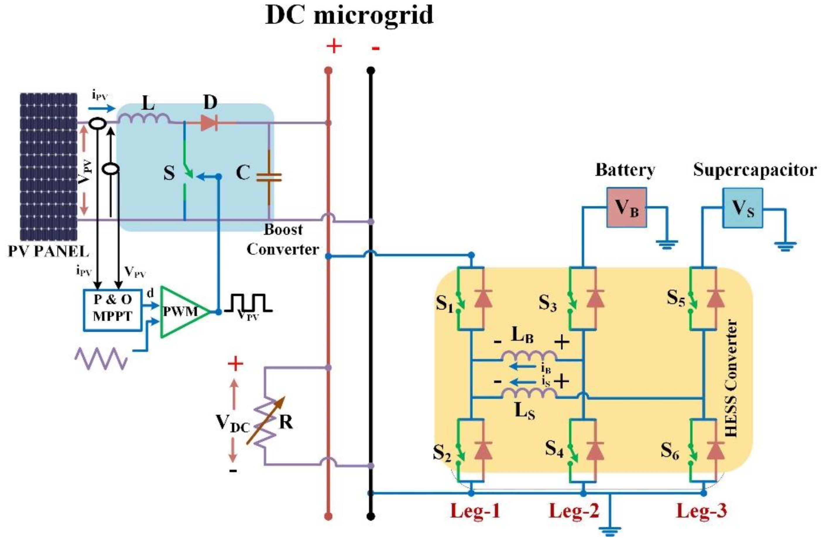
Smartcities 05 00024 g001
Figure 2. HESS and PV system in a DC microgrid design.
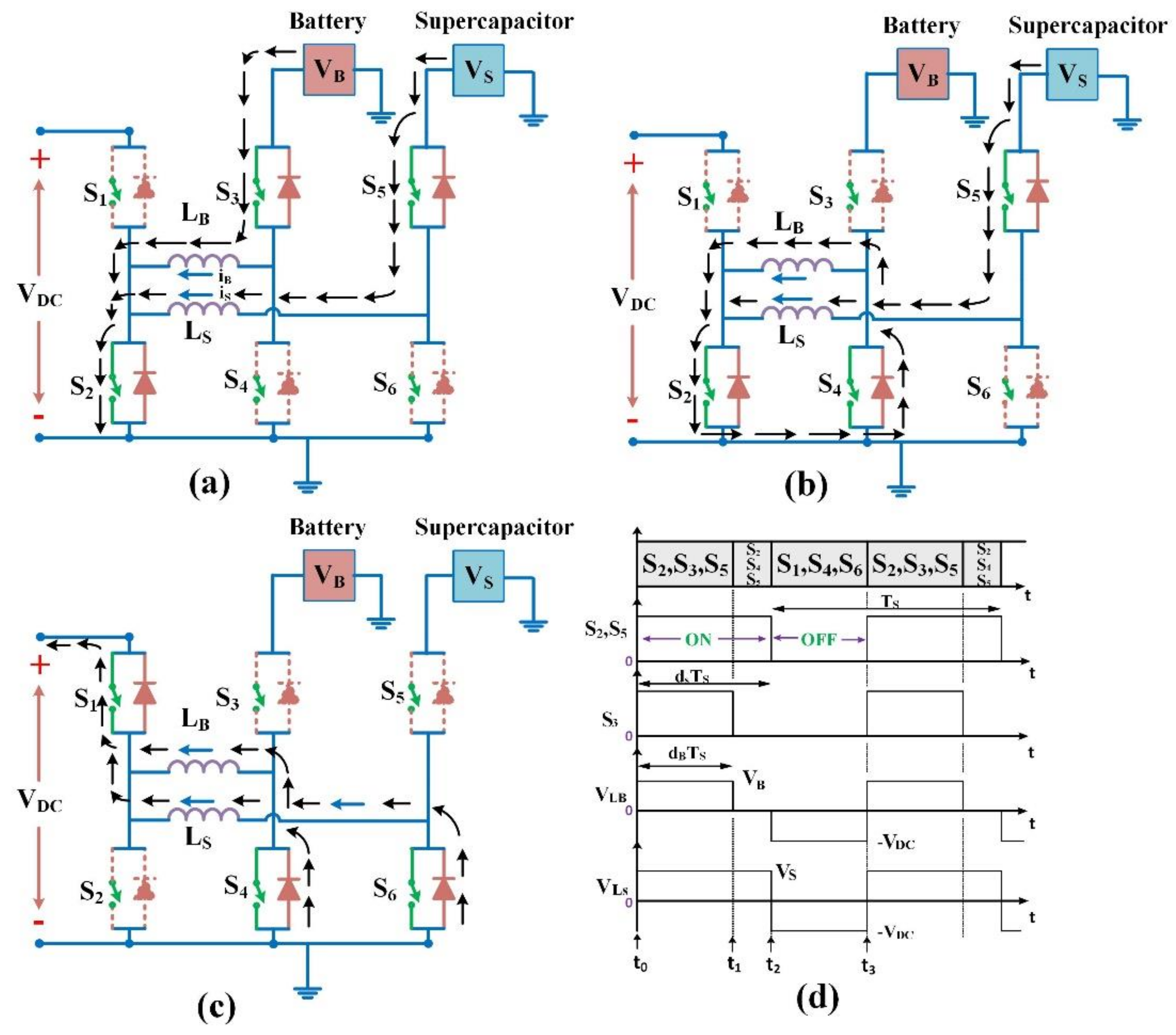
Smartcities 05 00024 g002
Figure 3. Two-input bidirectional converter equivalent circuit. (a) Operating switches S2, S3 and S5; (b) operating switches S2, S4 and S5; (c) operating switches S1, S4 and S6 and (d) discharging mode steady-state waveforms.
Smartcities 05 00024 g003
Figure 4. Two-input bi-directional converter equivalent circuit. (a) Operating switchesS1, S4 and S6; (b) operating switches S2, S4 and S5; (c) operating switches S2, S3 and S5 and (d) steady-state waveforms in discharging mode.
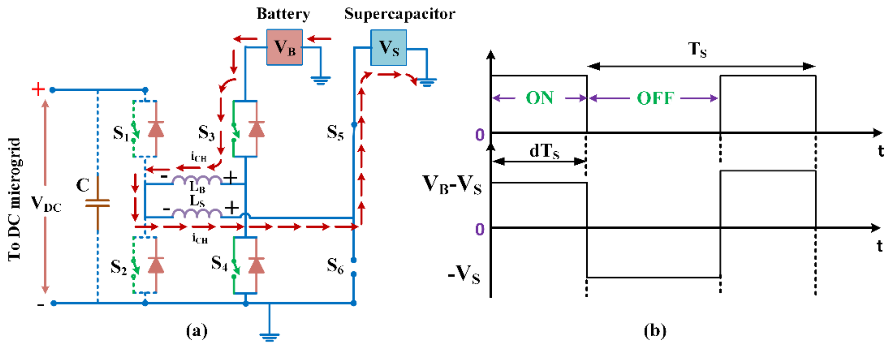
Smartcities 05 00024 g004
Figure 5. HESS energy exchange method of operation: (a) equivalent circuit and (b) steady-state waveforms.
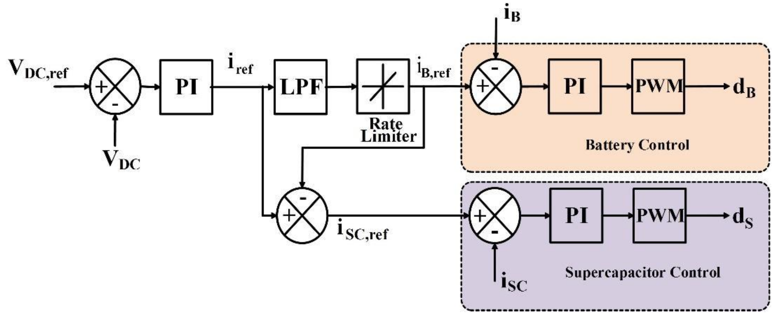
Smartcities 05 00024 g005
Figure 6. Description of the overall control mechanism for the current bifurcation between the SC and the battery unit for the PI control scheme.
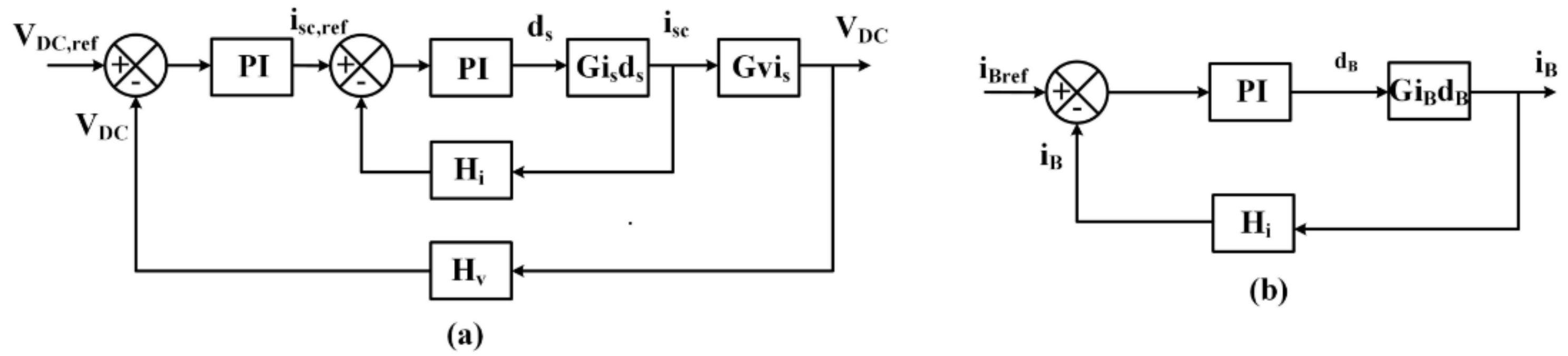
Smartcities 05 00024 g006
Figure 7. Overall block diagram: (a) representation of supercapacitor control logic and (b) representation of battery control logic.
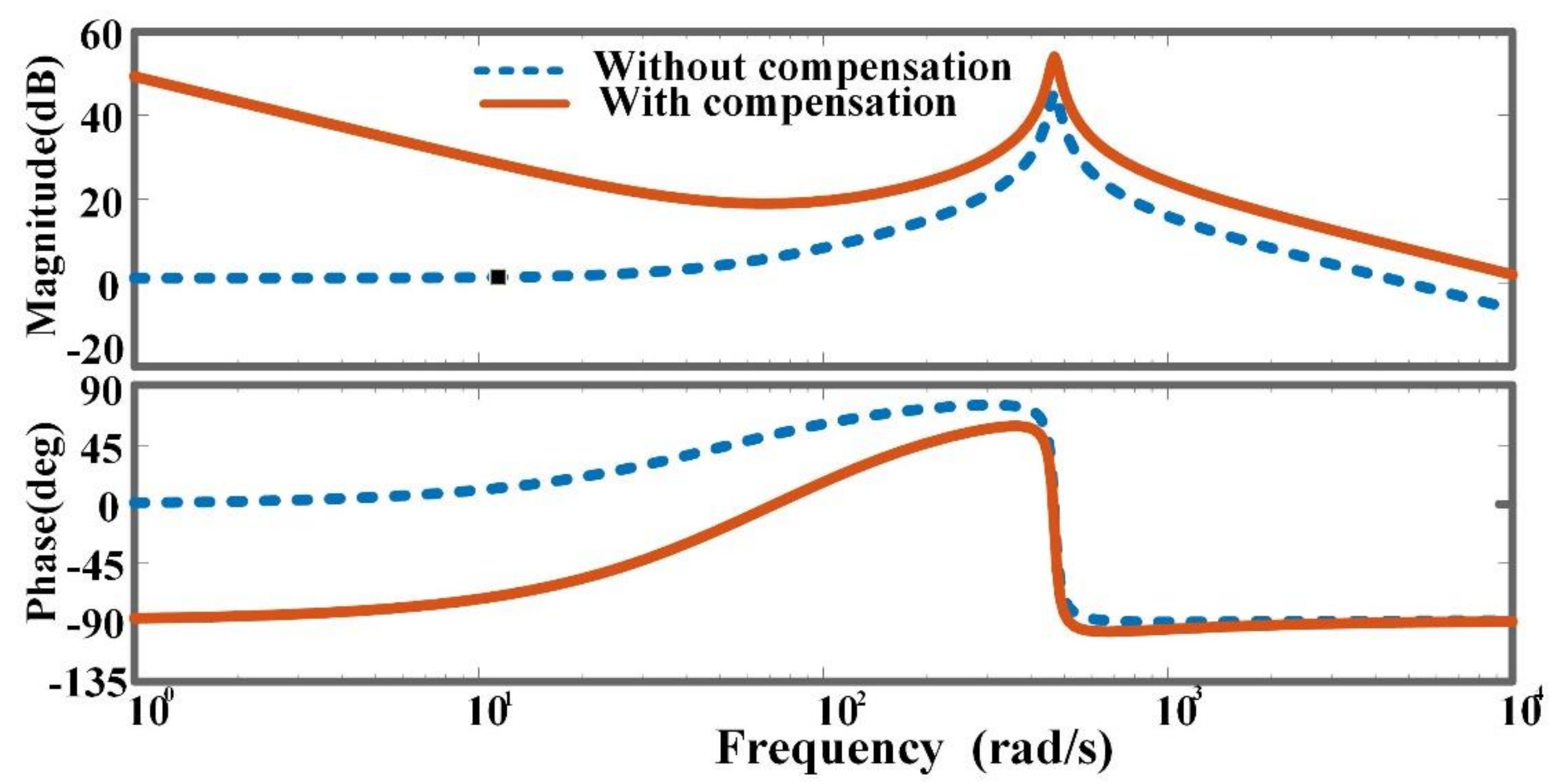
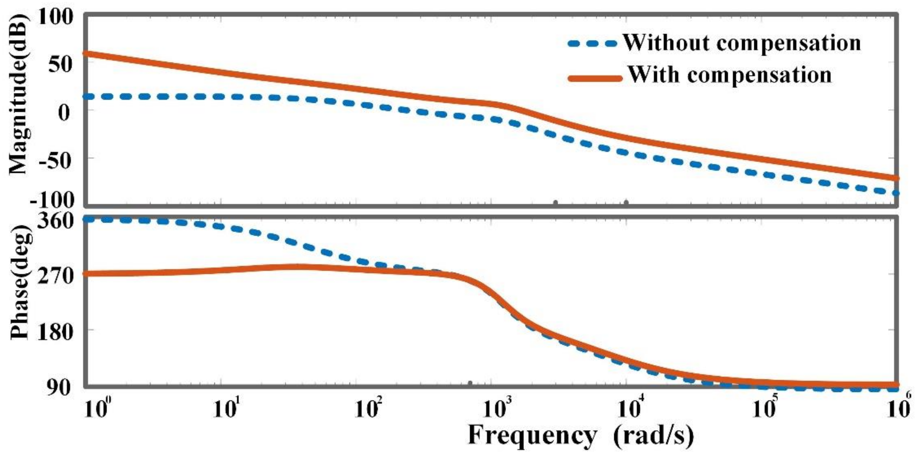
Smartcities 05 00024 g007
Figure 8. With and without compensation, a Bode plot of the inner SC current logic.
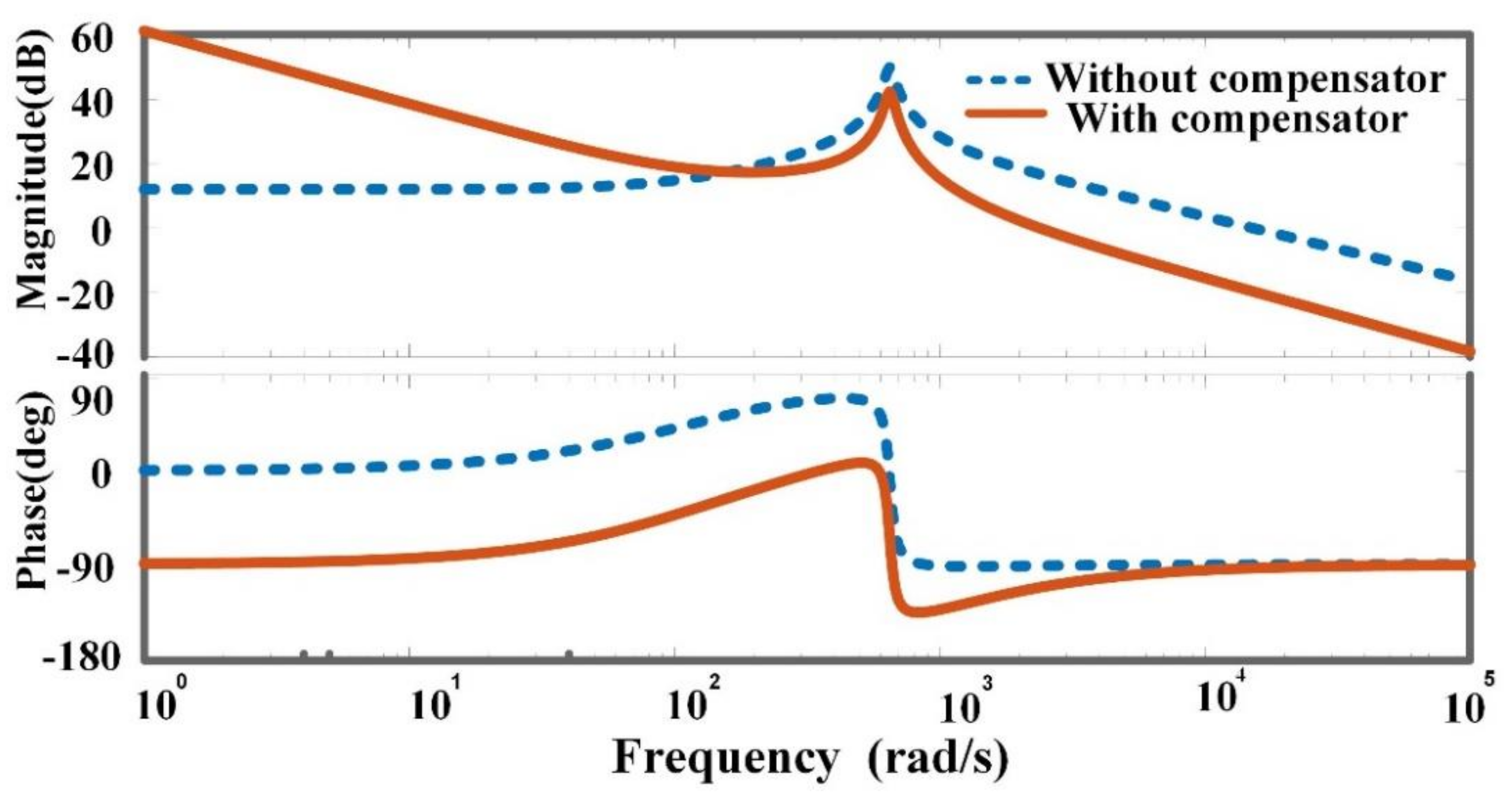
Smartcities 05 00024 g008
Figure 9. With and without correction, an open-loop Bode plot of battery current logic is shown.
Smartcities 05 00024 g009
Figure 10. Bode diagram of the outer voltage logic in open loop with and without compensation.
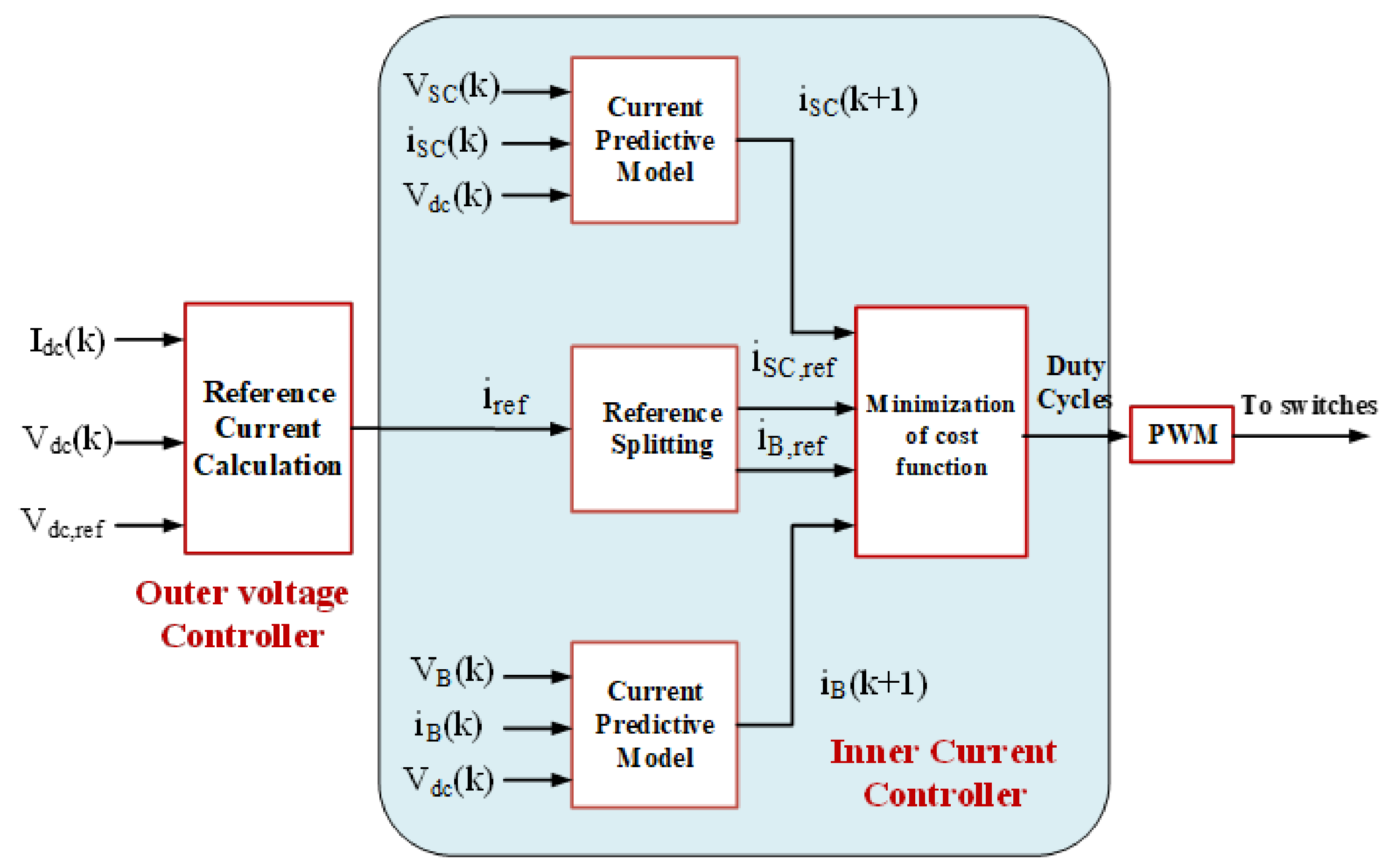
Smartcities 05 00024 g010
Figure 11. Block diagram representation of MPC for HESS.
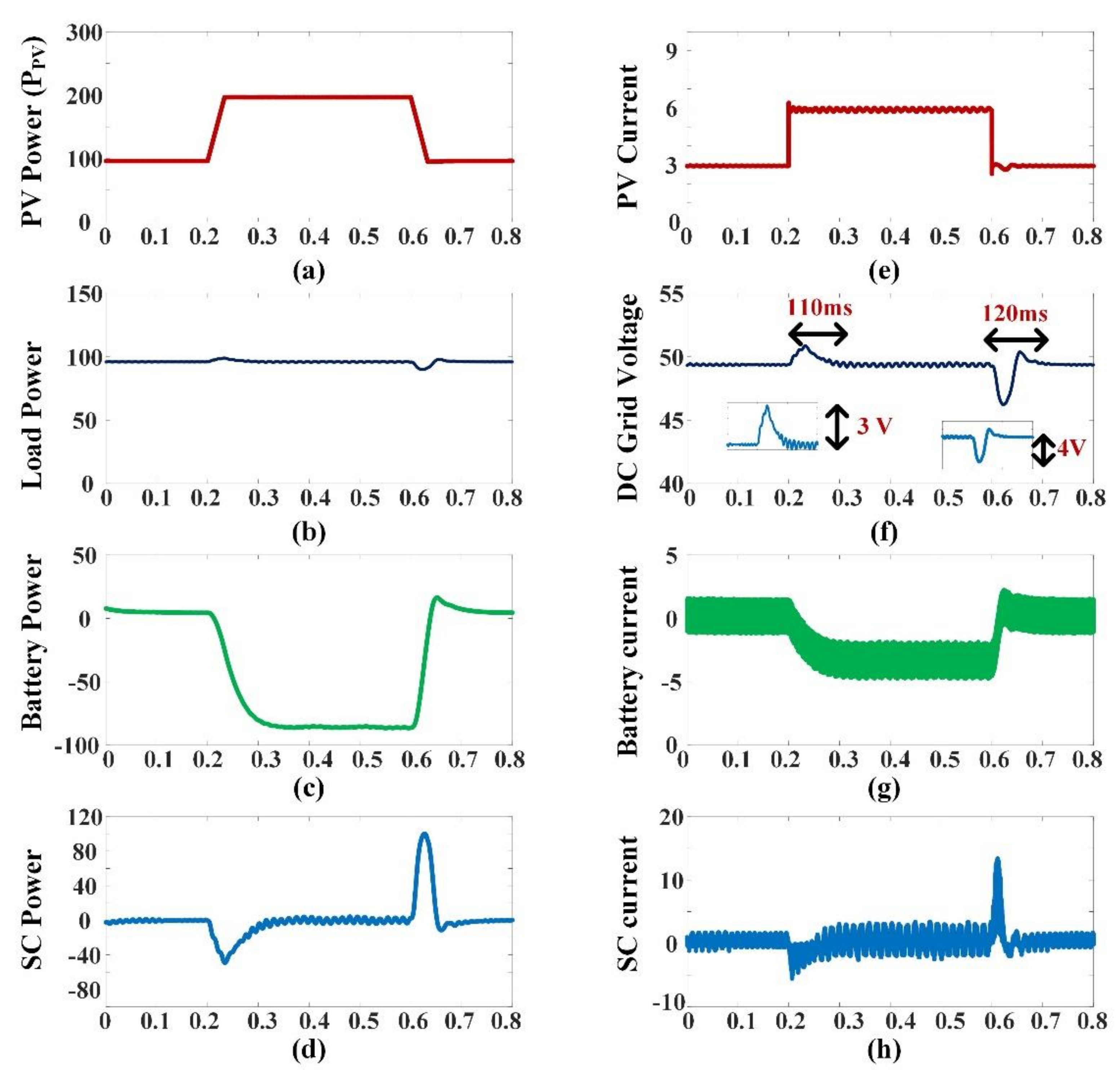
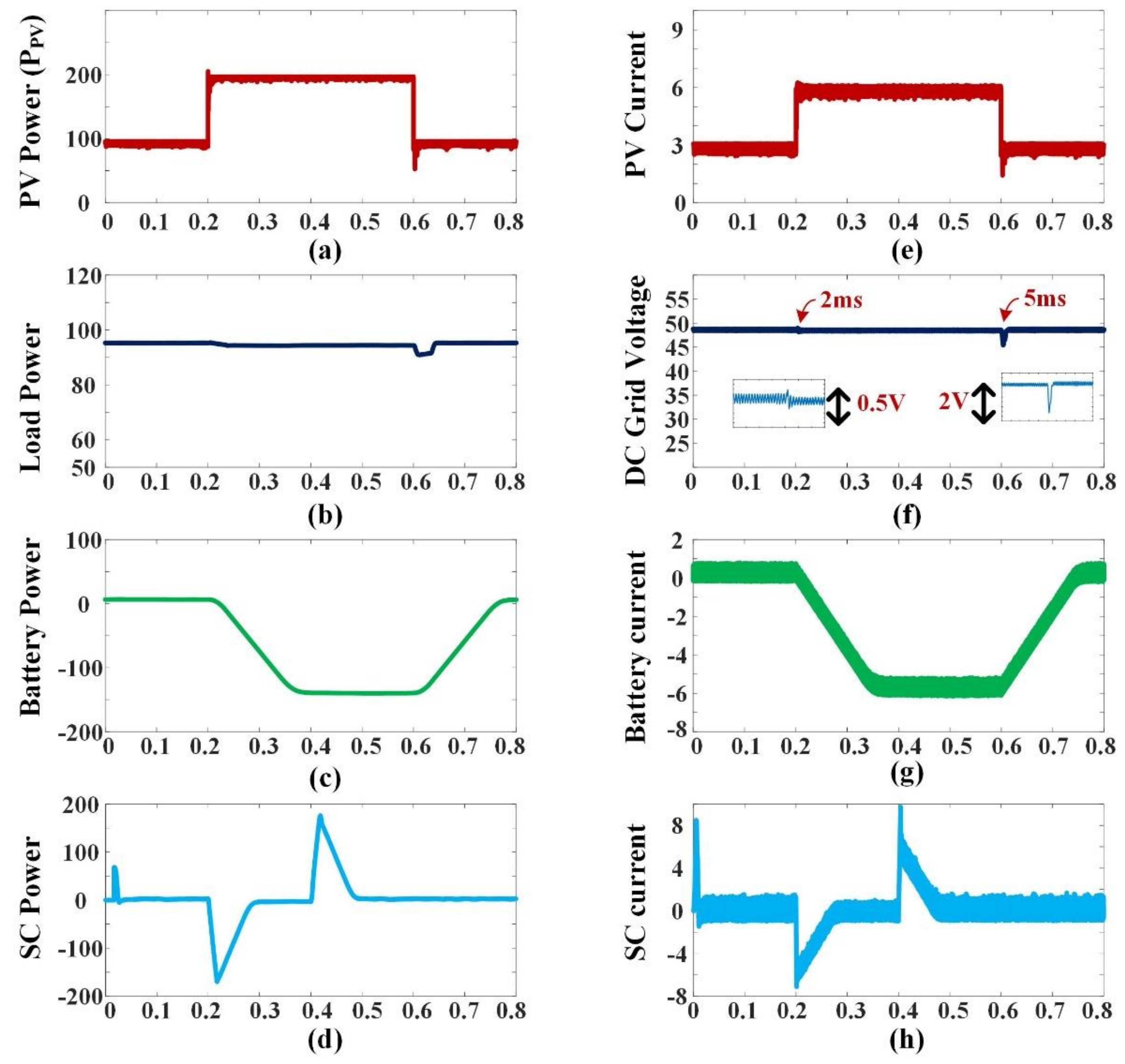
Smartcities 05 00024 g011
Figure 12. Change in PV generation using a PI control system simulation. (a) PV power, (b) output load power, (c) battery storage power, (d) SC storage power, (e) PV current, (f) DC microgrid voltage, (g) battery storage current and (h) SC storage current.
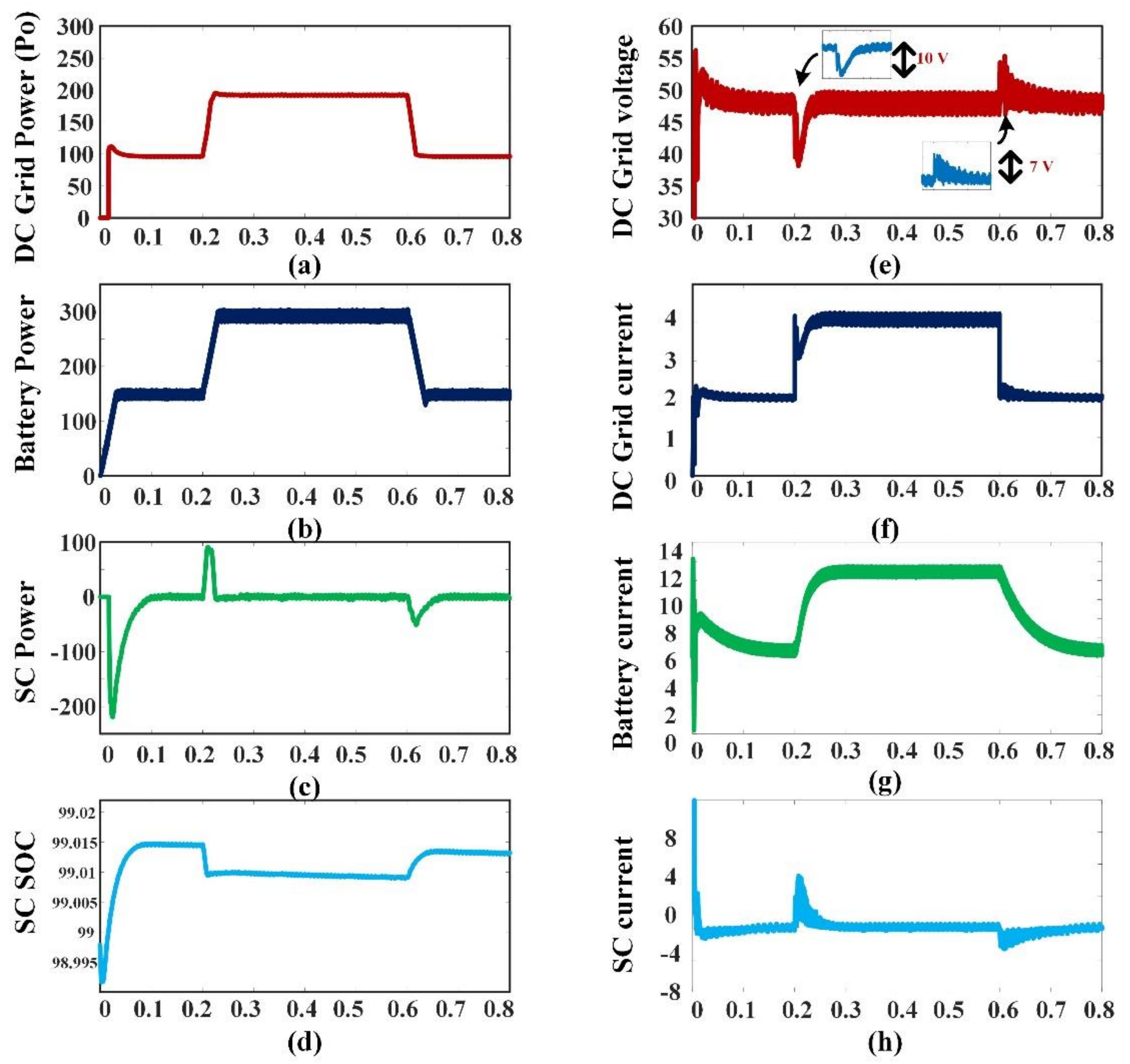
Smartcities 05 00024 g012
Figure 13. The simulation findings for a change in load demand are as follows: (a) DC microgrid power, (b) battery storage power, (c) SC storage power, (d) SC SOC, (e) DC microgrid voltage, (f) DC microgrid current, (g) battery storage current and (h) SC storage current.
Smartcities 05 00024 g013
Figure 14. Simulation findings for MPC control of a step change in PV generation (a) PV power generation, (b) load power demand, (c) battery storage power, (d) SC storage power, (e) PV current generation, (f) DC microgrid voltage, (g) battery storage current and (h) SC storage current.
Smartcities 05 00024 g014
Figure 15. Simulation results for a load demand step change—(a) DC microgrid power demand, (b) battery storage power, (c) SC storage power, (d) SC SOC, (e) DC microgrid voltage, (f) DC grid current, (g) battery storage current and (h) SC current.
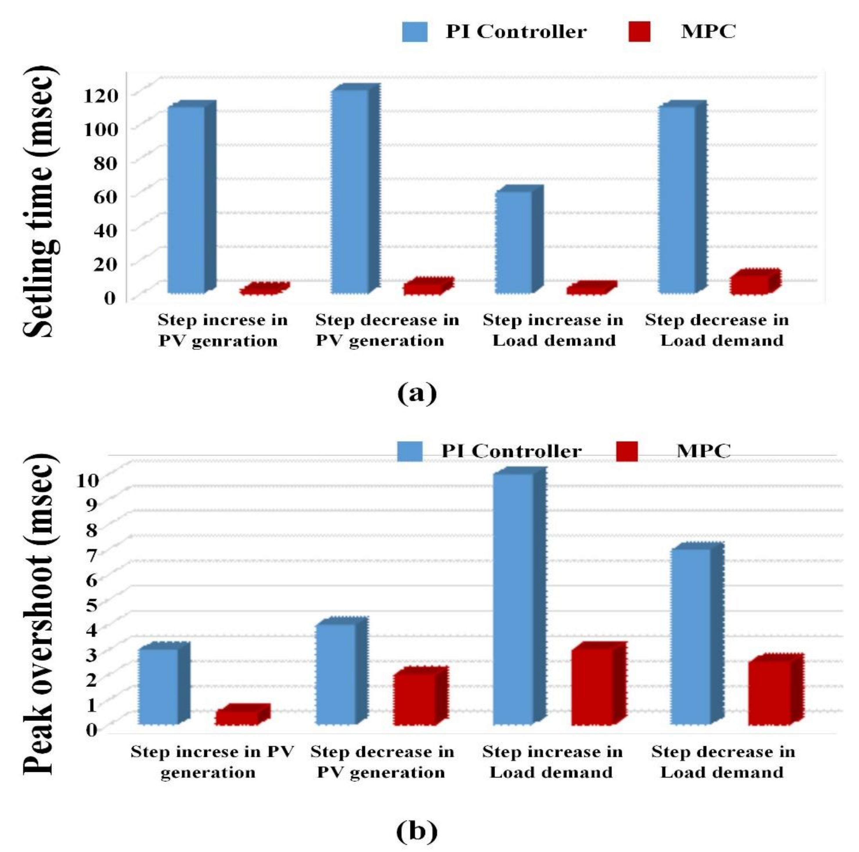
Smartcities 05 00024 g015
Figure 16. Graphical comparison of PI controller performance over MPC: (a) settling time and (b) peak overshoot.
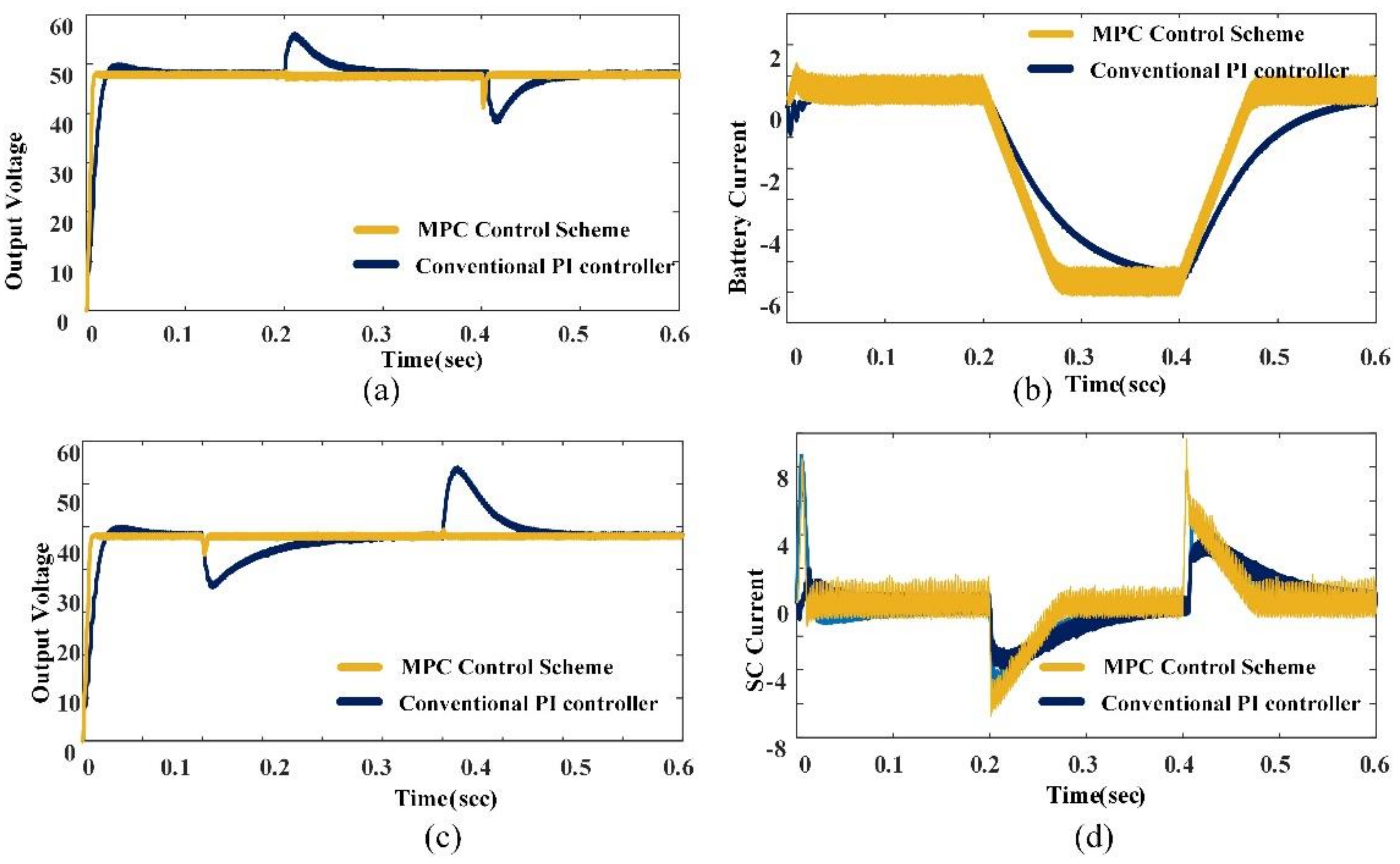
Smartcities 05 00024 g016
Figure 17. Comparative performance of PI controller over MPC: (a) step change in PV, (b) battery current, (c) step change in load demand and (d) SC current.
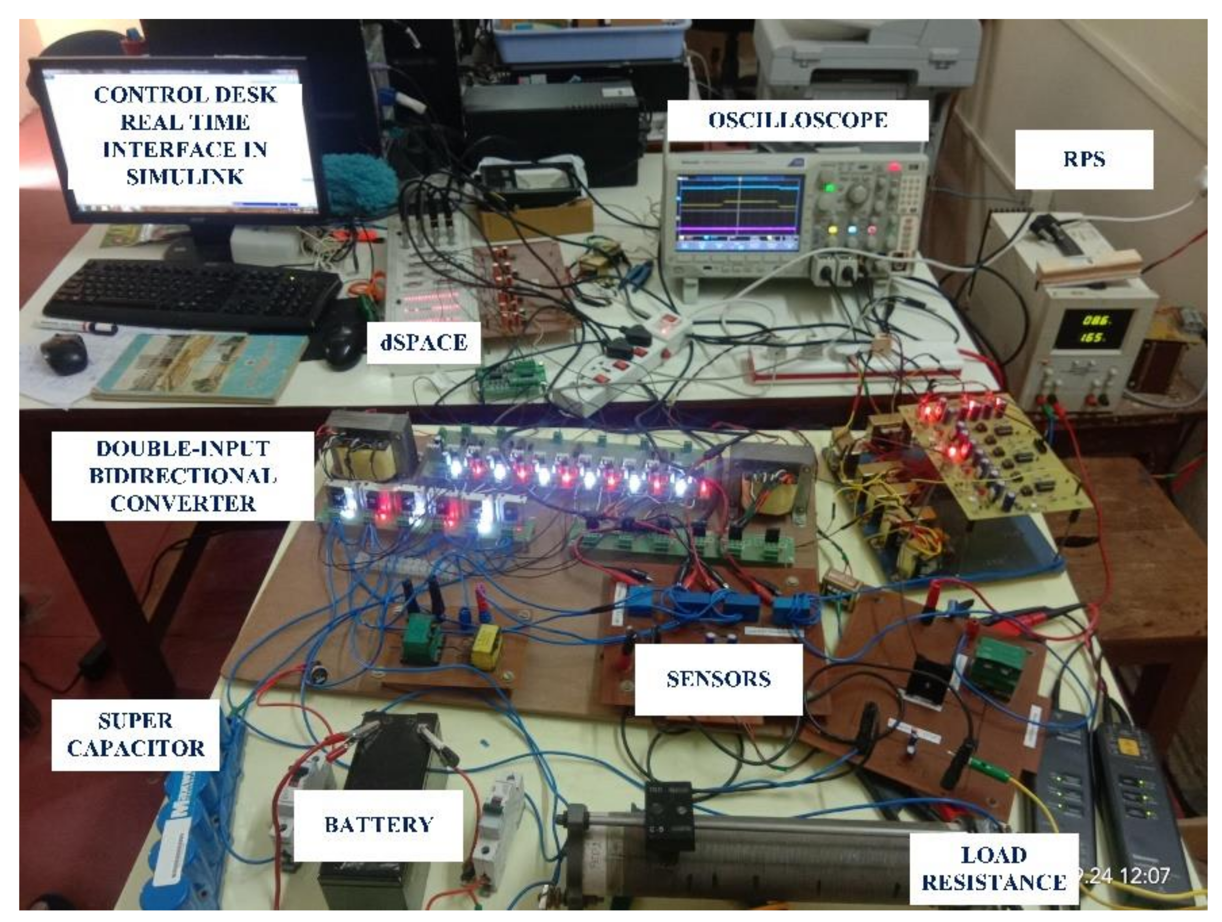
Smartcities 05 00024 g017
Figure 18. Hardware prototype developed for HESS.
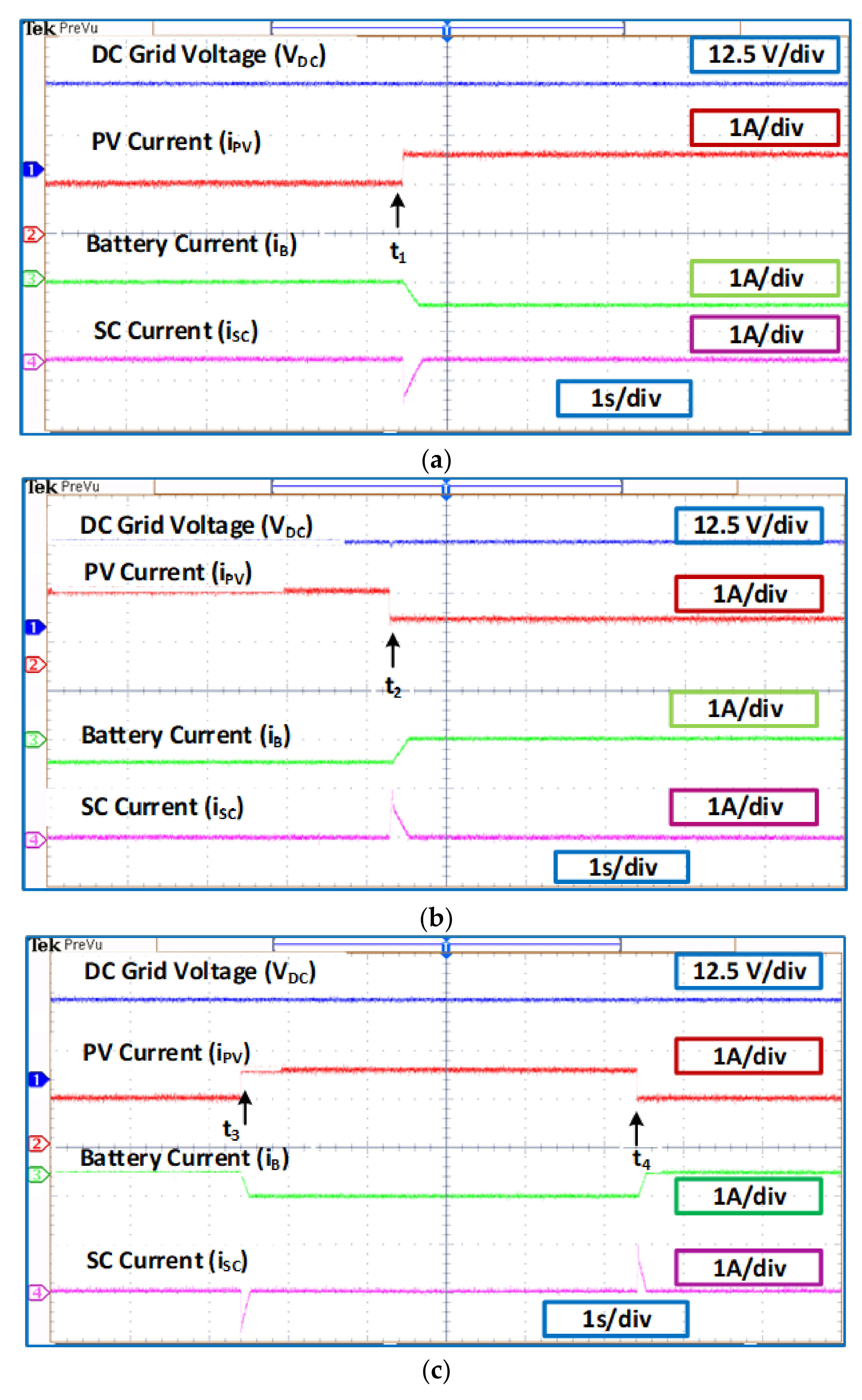
Smartcities 05 00024 g018
Figure 19. Experiments on a step change in PV production have yielded promising results. (a) Step increase in PV generation, (b) step decrease in PV generation and (c) step increase and decrease in PV generation.
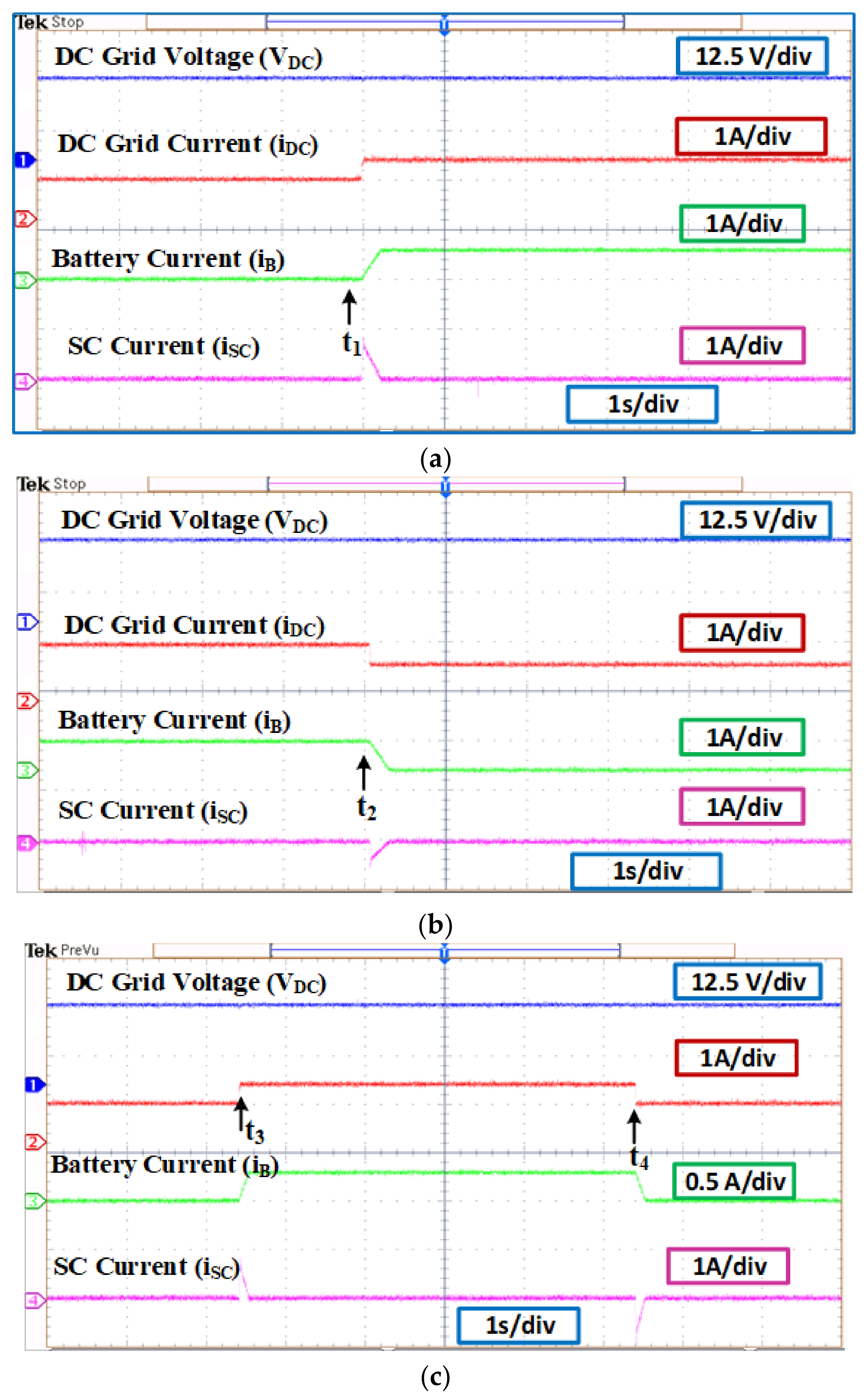
Smartcities 05 00024 g019
Figure 20. Experiments on a step change in load demand yielded the following findings: (a) step increase in load demand, (b) step decrease in load demand and (c) step increase and decrease in load demand.
Smartcities 05 00024 g020
Table 1. Switching operation in various time intervals.
Time ScaleT1T2T3
Operating switches(S2–S3–S5)(S2–S4–S5)(S1–S4–S6)
Table 2. Changing states at various periods of time.
Time ScaleT1T2T3
Operating switches(S1–S4–S6)(S2–S4–S5)(S2–S3–S5)
Table 3. Relationship between different voltages.
S. NoMode of OperationTransfer Function
1Power transfer from Battery–SC bank to the DC grid V DC = d S 1 d S . V S ,   V DC = d B 1 d S . V B
2Power transfer from DC grid to Battery–SC V S = d S 1 d S . V DC , V B = d S 1 d B . V DC
3Energy exchange mode V S = d . V B
Table 4. Linear averaged transfer functions for small signals.
S. No.ParameterTransfer Functions
1SC current transfer function control G i SC d SC = i SC s d SC s = V DC 1 + d SC R ( 1 d SC ) 3 1 + S RC 1 + d SC S 2 L SC C ( 1 d SC ) 2 + S L SC R ( 1 d SC ) 2 + 1
2SC current to transfer function output voltage G v DC i SC = V DC s i SC s = R 1 d SC 1 + d SC 1 S d SC L SC R ( 1 d SC ) 2 1 + S RC 1 + d SC
3Control to battery current transfer function G i B d B = i B s d B s = V DC d B R ( 1 d SC ) 2 . 1 + SRC S 2 L B C ( 1 d SC ) 2 + S L B R ( 1 d SC ) 2 + 1
4Inner SC current loop PI controller transfer function G pi , SC = K p . SC + K i , SC S
5The transfer function of the battery current loop was controlled by a PI controller. G pi , BAT = K p , b + K i , b S
6Outer voltage control loop PI controller transfer function G pi , v = K p , v + K i , v S
Table 5. Simulation study system parameters.
S. NoParametersValue
1MPPT voltage (Vmppt)31.95 V
2MPPT current (Imppt)3.05 A
3MPPT power (Pmppt)96.05 W
4SC voltage (VSC)32 V
5SC storage inductance (LS)0.365 mH
6Battery voltage (VB)24 V
7Battery storage inductance (LB)0.35 mH
8Boost converter inductance (L)4.2 mH
9Load resistance (R)24 Ω
10DC grid voltage (VDC)48 V
11Output capacitance (C)400 µF
Table 6. Parameters for implementing a DC microgrid.
S. NoParametersValue
1SC component voltage (VSC)10 V
2SC component inductance (LS)1.43 mH
3Battery component voltage (VB)12 V
4Battery inductance (LB)4.8 mH
5Boost converter inductance (L)4.1 mH
6Load resistance (R)25 Ω
7DC microgrid voltage (VDC)20 V
8Filter capacitance (C)150 µF
Publisher’s Note: MDPI stays neutral with regard to jurisdictional claims in published maps and institutional affiliations.

