1. Introduction: Historical References and Concept
In a global world, transport, both passengers and cargo, has become a strategic sector for the economy. That has implied an important increase in logistics, and transport has increased three times since 1950. Unfortunately, and as the European Environmental Agency has assessed, in 2016, the transport sector contributed 27% of total European greenhouse gas emissions [
1]. Different European policies have established a reduction of them in two thirds by 2050 if compared with 1990 levels in order to meet the long-term 60% greenhouse gas emission reduction target as set out in the 2011 Transport White Paper.
Within this scenario of expansion of transport, congestion at the infrastructures, increase of CO
2 emissions, and dependence of fossil fuels is where the need for clean, sustainable, and efficient transport technologies is critical. As a result of these requirements, the concept of Hyperloop was launched in 2013 [
2] as a new magnetically levitated ultrafast train, travelling along a tube under low pressure. Currently, there are several technological developments following the concept [
3]. Some of them are in America [
4], some others in Europe [
5], and some in Asia [
6].
The concept of Hyperloop could have some similarities with the very-high-speed trains developed in the 20th century, such as the magnetic levitation (MAGLEV) trains [
7,
8]. As a matter of fact, the first references about the Hyperloop concept are from the 17th century, when Denis Papin, a French physicist, envisaged the delivery of mail through pressurized air tubes. Later, in the 19th century, these ideas were materialized with the development of the London Pneumatic Dispatch Company (UK), presented in 1868 (
Figure 1a). In 1867, in New York (USA), Alfred Ely Beach invented a similar device (see
Figure 1b) which would become the first concept of suburban transport.
Nowadays, the scope of operation for this technology, both for freight railway and passenger traffic, is to connect distances in the range of 1000 km with the speed in the range of 700–1000 km/h. Several studies have been conducted recently in order to analyze the economic viability of this solution for both applications [
9,
10]. Within this speed range, the use of catenary and pantograph systems is not feasible because of the mechanical restrictions. Alternatively, the use of linear motors is preferred for traction.
Hyperloop technology is based on a railway line inside a pressurized tube where several moving parts, hereafter capsules or pods, are travelling with a frequency in the range of 2 and 6 min between capsules. Beyond these basics, different developers propose different technology details.
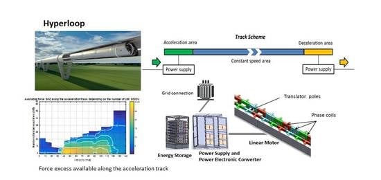
Figure 2 shows the technology by the Spanish company ZELEROS (Valencia –Spain-) [
11], used in this paper as a case study to analyze the power supply in this application.
The solution proposed by ZELEROS comprises a rail line divided roughly into three areas, presented in
Figure 3:
Firstly, an acceleration area, between 5 and 10 km, where the capsule is accelerated with the help of a linear motor installed along the rail. During this period, the capsule achieves a speed close to the maximum speed. Although different options are possible for the traction motor, it is preferred the one with less weight in the moving part and more simplicity in the coils supplied along the track line. Some details of the linear motor proposed are provided in
Section 2.
Secondly, a cruise speed area, where the capsule maintains the maximum speed. The losses are compensated by means of an on-board propulsion system based on a reaction turbine. In the case of study, a compressor gets the air in front of the capsule, compresses it, and subsequently, it is expanded in the reaction turbine, in a similar way to an aircraft. This air is not only used for the propulsion of the capsule but also for the levitation in order to minimize the mechanical friction. The energy used for this process is covered by a set of batteries located on-board of the capsule. Obtaining the power supply for the on-board propulsion system is an additional technological challenge. However, they are out of the scope of this paper, and the details about it are classified. Nevertheless, it is worth mentioning that lithium-ion batteries have been proposed and analyzed as a solution due to the high energy density, low losses, and the appropriate power and energy ratio required for the track lengths under study. In this analysis, the pod is just a certain mass, which needs to be accelerated and decelerated. The weight of the batteries has been included in the total mass.
Finally, when the capsule arrives at the destination, it needs to be braked in a third area, named the deceleration area, using regenerative braking to recuperate part of the kinetic energy of the capsule. Additional braking systems are installed at the capsules in order to act in case of emergency. Due to the fact that most of the kinetic energy achieved on the travelling pods can be recuperated by regenerative braking, also considering that the losses are reduced because of the reduced pressure and levitation, the energy is likely to be reused for further acceleration of other pods travelling in the opposite direction.
The paper aims at analyzing the different options for the power supply of this system, focusing on a specific technology for the linear motor. It is focused on the study of the power supply alternatives for the acceleration of the pods.
Section 2 presents the system specifications according to which the power supply solution is defined.
Section 3 presents the solution of linear motor used for this technology. Then,
Section 4 analyses the different options for power supply in similar technologies. As a result, this section justifies the selection of an energy storage solution as a power supply for the system. Some calculations are additionally included to quantify the size of the energy storage requirements. Finally,
Section 5 presents the practical implementation of a first reduced-scale prototype of the acceleration system, to be developed during 2020 and commissioned in 2021. Some particular scaling recommendations are included in order to get the maximum advantage of the reduced-scale prototype, considering the development of a commercial-scale version.
The main contributions of the paper are the proposal of an alternative solution for the power supply of Hyperloop railways, consisting of an energy storage system which supplies a linear motor drive during the acceleration of the pods. The impact of this solution could be high since it would allow the installation of Hyperloop stations mostly everywhere, without special requirements of the electric grid. The paper also presents a discussion of the different options and justification of the solution selected. Additionally, it presents a methodology to define and calculate the complete power supply system. It combines the design of the linear motor, the energy source and power electronics definition, and the distribution of the power supply along the acceleration area. Only a preliminary calculation of the energy storage system is provided, waiting to have more details about the energy losses related to the pod circulation along the low-pressure tube.
This paper is an extension of the work presented during the II Ibero-American Congress of Smart Cities (ICSC-CITIES 2019) celebrated in Soria (Spain) in October 2019, later selected to be published by Springer in the Proceedings of the Congress [
12]. The CIEMAT Institute, the author of this work, is collaborating with the Spanish company ZELEROS in the development of the acceleration device and the power supply of the technological solution proposed.
2. Specification of the Power Supply for the Hyperloop System
The starting point of the study was to consider the technical specifications required by the system. They were provided by the company ZELEROS and compiled in
Table 1.
One of the main challenges of the power supply of this transport system is that, and due to the ultrahigh speed, the moving part (pods) cannot be supplied by means of a conventional pantograph. This technology is only valid below 500 km/h because of mechanical limitations. Beyond that value, the solution of a linear motor deployed along the track is the most commonly used. An active part comprising electric coils is allocated on the track while the passive part of the electric motor is located on board. Additionally, such high speed would produce excessive friction between the moving part and the rail, and wheels cannot be used at that speed range. It is therefore mandatory to use some type of levitation in order to make the operation viable. Some examples are currently operating, such as the Transrapid and the Japanese MAGLEV JR-Maglev MLX, both magnetically levitated (MAGLEV).
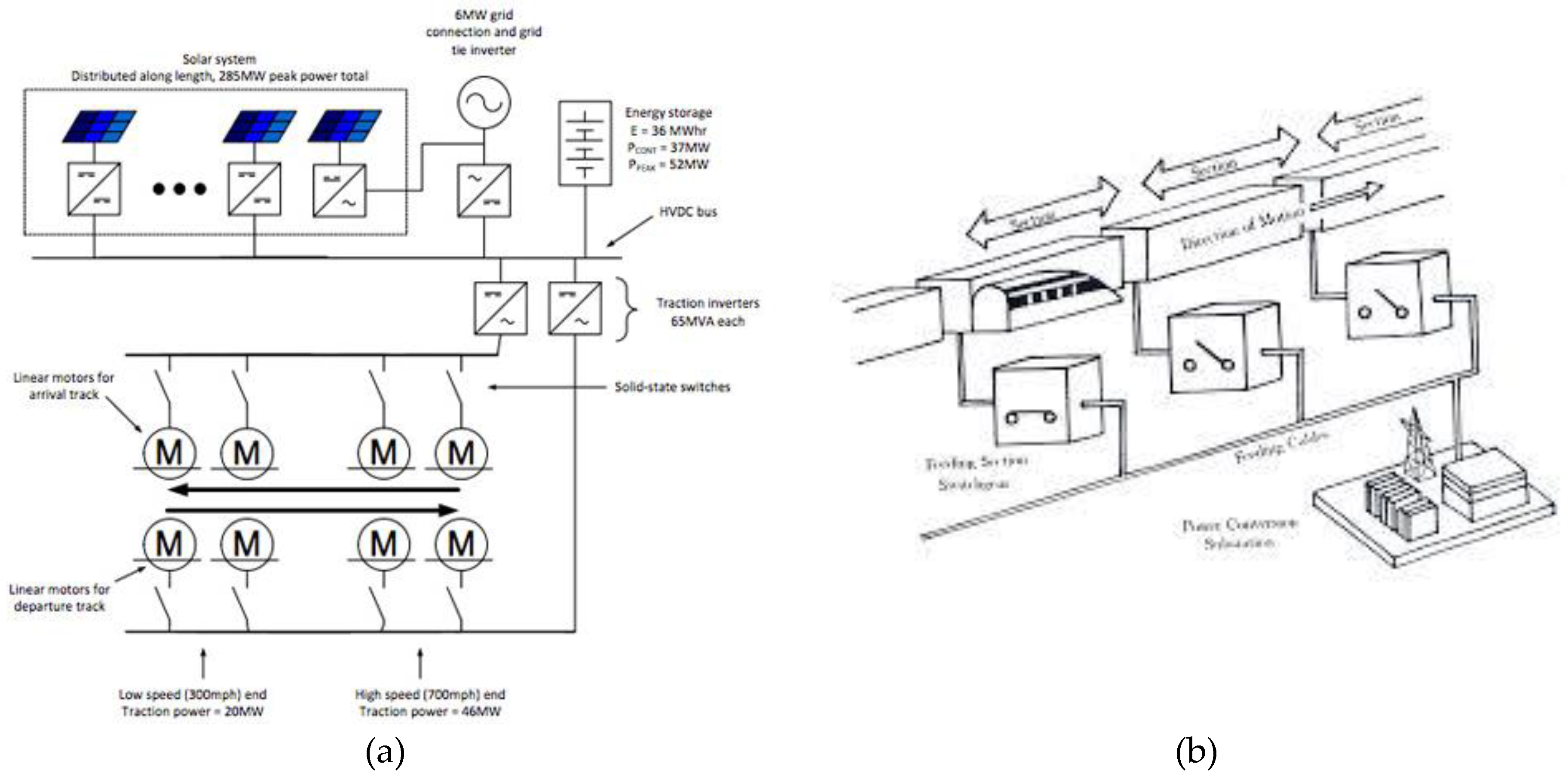
All MAGLEV trains, as well as some of Hyperloop technological proposals, consider a linear motor, and therefore power supply, all along the track. That means a complicated set of high-voltage power lines and power electronic converters. As a consequence, there is an important constrain on the track length in order to keep the infrastructure cost within reliable limits. Some examples of power supply used for MAGLEV and Hyperloop solutions are presented in
Figure 4.
On the contrary, the solution proposed by ZELEROS comprises: an acceleration area on the track, where a linear motor is installed and the pods are taken to the cruise speed; then a constant speed area of the track, where the speed is maintained by means of a propulsion system mounted on board and supplied by batteries; and finally a deceleration area of the track, where the pods are slowed down. This way, the longer the track, the more important the cost reduction of the power supply is in the total budget.
Figure 4 presents a simple scheme of this structure.
Once the technical specifications for the dynamics of the system are selected, the first decision is to define the acceleration profile along the acceleration area. It is possible to choose a constant acceleration by applying a constant force, but it produces a very high maximum power level (around 15 MW in the study case); or, on the contrary, to select a more typical profile in industrial electric drives consisting of the first section of constant force and another section of constant power [
13]. In this case, the maximum power is lower (10 MW for the case study) and therefore more convenient for the design of electric equipment, although it requires a higher force value in the first section. The second option is preferred since it gets better dynamics for the moving capsule and reduces the maximum power, as well as the current intensity, during the acceleration process. Force and power profiles will be later described in
Section 5, where the design of the reduced scale is addressed.
The methodology to design the complete system is developed through the following steps:
Based on the specifications and dynamic calculations, predesign of the linear motor and analysis of the electromechanical variables by means of finite elements (FEM).
Based on the dynamics and basic data related to the track and conductors, selection of the number of power supply sections in order to fulfill the current and voltage requirements.
Once the power supply sections are defined, the linear motor should be validated all along the acceleration area in order to check that the force is properly delivered during the whole range.
Unfortunately, the simple profile commonly used in electric drives is not optimal for this application. There are some areas along the acceleration section where the linear motor performance is insufficient and the back electromotive force is too high for the voltage available. As a consequence, the distribution of different types of coils along the acceleration area of the track is not uniform and leads to an asymmetrical deployment of the power supply and cabling. Authors believe that it would be very beneficial to modify the dynamic force and power profiles. An upgraded profile, where the power is composed of three sections, leads to a more homogeneous distribution of the coils along the track and to better use of the current levels. The implementation of this upgraded profile is presented in a case study included in
Section 5 of the paper.
3. Selection and Design of the Linear Motor
The requirements to reduce at maximum the weight of the moving part lead to allocate the coils of the linear motor, named the active part, on the track [
8]. Linear motion systems (LMSs) usually rely either on synchronous or asynchronous machines [
13]. The former are far more widespread (Shanghai airport shuttle in China and JR in Japan), but the technology is expensive for long tracks; meanwhile, the latter are more economically competitive but have an excessive amount of losses on-board. As an alternative, the use of a switched reluctance machine is proposed. Despite having lower performance, it offers immense advantages as it saves costs and material while still allowing the system to transport high capacities at high speeds. Particular benefits of this linear motor technology: very light on-board part with low losses rate, robustness, high force density, and the possibility to operate in degraded mode when any of the phases fails [
14]. An example of the electromagnetic analysis of the potential design of switched reluctance linear motor is presented in
Figure 5. That solution corresponds to the particular case of the prototype defined in
Section 5.
A power electronic converter based on a three-phase full-bridge topology [
15] was selected to drive this motor. The operation and the current waveforms of a similar switched reluctance machine (SRM) are presented in
Figure 6, for the sake of example.
4. Analysis of Options for the Power Supply of the Linear Motor
Once the linear motor and the power electronics are defined, the next step is to define how the system receives power and delivers it into the motor in order to accelerate it. Two basic options are proposed: direct power supply from the electric grid or power supply by means of an intermediate energy storage system.
4.1. Direct Connection to the Electric Grid
This scheme has the main advantage of allowing the use of high voltage, very convenient for the supply of the linear motor with many coils connected in a series in order to compensate for the voltage drop, allowing the use of lower current levels and therefore increasing the efficiency. However, the main inconvenience is a higher cost of a high-voltage infrastructure. Although no particular cost values could be gathered, it is well known that high-voltage equipment is in the order of 3 times more expensive (Red Eléctrica de España-REE). Moreover, the power level required, maximum of 10 MW, the relatively short length of the acceleration areas, around 10 km, and especially the short time of utilization of the power, in the order of 100 s, do not justify enough the investment in a dedicated infrastructure of high-voltage power supply.
As an alternative, it has been proposed to consider the use of energy storage systems, more flexible in utilization, without the requirement of a high power supply node.
4.2. Power Supply through an Intermedium Energy Storage System
The use of energy storage systems in the railway sector has some references, mostly in order to avoid the waste of energy during braking or to reduce the use of infrastructure. It is quite common to find light trains and trams with energy storage systems on board [
16], more efficient than stationary solutions. However, the use of stationary energy storage devices is more convenient from the economic point of view, as well as to reduce the maximum power requirements to the grid [
17].
4.3. Analysis of Energy and Power Requirements for the Energy Storage Device
According to the constant power profile from
Figure 7b, the theoretical amount of energy required for the acceleration of the moving capsule (not considering the efficiency of the system or the additional power consumption of the auxiliary systems involved) with a maximum power of 10 MW can be estimated as the area under the red curve. A value of 217 kWh was obtained, as presented in (1).
Among the different energy storage technologies already existing in the market, three of them were selected according to their maturity level and the characteristics of high power, not very high energy and very fast response.
4.3.1. Batteries
The sector of the electric vehicle has triggered the development of batteries for this and other applications. Batteries are being applied for a wide variety of grid services. However, this technology presents two important disadvantages when considering an application like the one under analysis: the power/energy ratio is in the range of 1 MW/1 MWh, excessive energy for the required one (the case under analysis requires 10 MW and 0.217 MWh). Additionally, the number of charge-discharge cycles needed by this application is in the order of several hundred cycles per day, much higher than the cycles supported by batteries before suffering a loss of capacity (in the range of 5000–25,000 cycles). The use of batteries with such a high rate of cycles would lead to replacing the batteries every few months, resulting in a non-reliable solution.
4.3.2. Supercapacitors
Supercapacitors are a quite appropriate solution for the application in Hyperloop power supply because the power/energy ratio offered by commercial solutions is in the order of 1 MW/(5–10 kWh), very similar to the level required by this application. The main disadvantage is that commercial products present a voltage isolation limit of 1500 V for the series connection of cells. This restriction constrains the use for high power applications. Although using topology with a middle point grounded is possible to increase the voltage level to 3000 V, it is a technology challenge to go beyond this limit in order to allow the use in MW power levels without increasing the current values in consequence. The supercapacitor market trend goes towards getting cells with double the energy by 2020 and with higher isolation limits. If that is the case, supercapacitors would become very suitable for this application and economically competitive compared with grid connection or batteries. Some commercial products have been considered and most of them provide the same performance and characteristics [
18]. The most restrictive parameter is the energy capacity, leaving the power capability underused.
4.3.3. Flywheels
Flywheels are also candidates because some characteristics (power/energy ratio and the number of cycles) are similar to supercapacitors. An additional advantage of this technology is that since power and energy are completely decoupled, commercial solutions are more flexible in terms of power and energy, and a more accurate design is likely to be selected to fit both parameters according to the application. However, the required high voltage level for the linear motor, in the order of 5000 V, has a negative influence in the feasibility of using flywheels, considering that the operation voltage of this technology is around 1000 V. It would require the use of a series connection, which would complicate the operation, or the development of high voltage adaptation through additional DC/DC converters, which would significantly increase the cost. As a result, this option was rejected.
5. Development of a 1/3 Reduced-Scale Prototype of Linear Motor and Power Supply
The first step before the development of a commercial line is the testing of a reduced-scale prototype to validate the technology. A 1/3-scale prototype of a linear motor and power supply system was selected in this case. The variables to be maintained from the initial design are: size and dimensions of the linear motor, force, current, and voltage. Only maximum speed is reduced, as well as the mass in order to achieve the maximum values with a much smaller track. The technical specifications for this system are presented in
Table 2.
Figure 7 presents the initial force (a) and power (b) profiles, according to the criteria defined in
Section 1 of the paper. The requirements of the current and voltage are obtained from those profiles and therefore the design of both the linear motor and the power electronics can be accomplished.
Starting from technical specifications and requirements for mass (
m), maximum force (
Fmax), maximum power (
Pmax), maximum speed (
vf), and acceleration time(
tf), and having considered a constant power profile, it is necessary to establish the moment in which the force stops being constant. Considering in a preliminary calculation that the electric energy consumed by the linear electric motor is completely transformed into kinetic energy, Equations (2) and (3) provide the value of
t1, defined by (4), as the time when the system changes from a constant force profile into a constant power profile.
For this particular case of reduced scale prototype, a three-segment power profile was defined, as introduced at the end of
Section 2. A 10% higher value for the maximum power peak was defined in order to improve the performance of the system.
Figure 8 presents the results, taking into account that the dynamics of the system are maintained in terms of journey time, maximum speed, and track length.
Figure 9 presents the scheme of the complete system composed by the linear motor, the power electronic converter, the energy storage system, and the grid connection.
5.1. Scheme of the Power Supply for the Reduced Scale System
The acceleration section needs a linear motor along 500 m in the reduced scale prototype. One of the linear motor design decisions is how to split the ampere-turns parameter into a number of coil turns and current level, taking into account the voltage drop and the power electronics design.
On the other hand, voltage requirements are also defined to compensate the electromagnetic force, the resistive voltage drop and the current transient over the inductance of the electric circuit, required to reach the current reference during the operation. As a result, the most suitable solution for the linear motor is to use different types of coils along the acceleration section. That is the best way to take advantage of the number of turns of the coil in order to adapt it to the back electromotive force (emf), according to the speed. The higher the speed the lower the number of turns of the coil. Five types of coils have been considered, with a number of turns varying from 12 to 4 when increasing the speed or the distance along the track.
The prototype under study comprises a power electronic converter with a voltage of 4000 V and a current of 3000 A. The limit on the voltage leads to defining different track sections, supplied independently and alternatively because the voltage is not able to cover the electromagnetic force, the resistance voltage drop, and the inductive effect of the whole linear motor. On the other hand, it is not necessary to supply all the coils along the acceleration area at the same time, just the section where the moving part is passing. The track sections group a number of linear motor coils, organized in what has been named unitary machines (UMs) in series. A UM is a set of coils corresponding to three phases and two pairs of poles. Every position on the track is equivalent to a force demanded, which is equivalent to a current value. Starting with the first track section, the number of UMs will be increased until a limit is reached in terms of voltage or current. Then, the first section is closed and a new track section is defined, following the same procedure. If a voltage limit is reached, a new track section with the same type of coil is considered. If the current limit is achieved, a new track section with a different type of coil is considered. A higher number of sections implies a higher number of switches to commutate the track sections and more cabling needed.
In order to reduce the number of sections, it would be convenient to increase the voltage level. Once the common voltage is reached, at the level of around 4000 V, new topologies such as multilevel power electronic converters [
19] should be considered in order to manage voltage in the order of 6000 V with conventional semiconductors. This type of technology also allows to get additional values such as a reduction of the force ripple, reduction of the commutation losses, and more controllability in the current performance.
Figure 10 represents the advantages of increasing the voltage from 4000 V to 6000 V by the available force along the track as a function of the number of unitary machines in a track section. The conclusion of these figures is that by increasing the voltage, the same extra force is available for a certain speed with a track section composed by roughly double the unitary machines, or double the number of coils. That means a lower number of sections and therefore less cabling and associated equipment for the track sections transition.
Force, and therefore current, is also related to the number of UM selected in each track section.
Figure 11 presents an analysis of the total force, at different positions along the acceleration track, and depending on the number of UM selected. For a certain speed, the higher number of UM is included in the corresponding track section, the lower force is required to develop by each UM.
Another important issue related to the current is the selection of the current density at the linear motor coils (in order to determine the coils cable section) and the selection of the different track sections to be supplied at the same time by the power converter. Two current density values, 20 and 40 A/mm
2, were analyzed in order to consider two design criteria for the linear motor and presented in
Table 3.
Table 4 complements the information of
Table 3 with the length of the different track sections along the acceleration area for the case study using 20 A/mm
2.
Table 4 presents 5 types of coils with 4, 6, 8, 10, and 12 turns per coil, respectively. The coils with a higher number of turns are located at the first part of the acceleration area of the track (lower speed and therefore no need to reduce back emf), while the coils with a lower number of turns are located at the final part of it (higher speed and therefore need to reduce back emf). Skin effect might be also considered in this application since quite high frequencies are operating at the high-speed area. They were already studied in a previous analysis [
12].
Position sensors will be deployed along the acceleration track in order to detect the presence of the pods. That will provide the closing of switches, connecting each track section to the power electronics converter. Only one track section is supplied by the power converter at the same time, only one power converter being necessary to supply the complete linear motor. That is an advantage compared to the power supply of previous similar concepts such as MAGLEV [
20], where different power converters need to be installed along the track for the power supply, requiring high-voltage equipment. The switches selected must be semiconductors. They have to be fast, robust, and able to manage high voltage. However, they do not need to reach a high commutation frequency since they are only switched on once per trip. Therefore, thyristors are the best option.
5.2. Preliminary Design of an Energy Storage System for the Power Supply
Based on the system specifications, a preliminary design of an energy storage system was carried out. The methodology starts with a dimensioning based on the energy required, secondly based on the voltage, by connecting storage cells in series, and finally by current, validating that the current required does not overcome the maximum value of the cells.
5.2.1. Energy Dimensioning
The energy required during the acceleration process is based on the kinetic energy associated with the maximum speed of the pod. For this preliminary calculation, efficiency from electric to mechanic conversion was considered 100%, but it must be upgraded with the different efficiencies involved in the conversion process (aerodynamic losses, magnetic levitation losses, and Joule effect losses at the linear motor and the cabling along the acceleration area). The energy is given by (5).
Selecting one of the commercial modules with an energy of 80 Wh (64 V, 141 F) and taking into account a depth of discharge until half of the nominal voltage, which means 75% of the total energy, the number of modules required to fulfill the energy is 90, as it is obtained from (6).
5.2.2. Voltage Dimensioning
The voltage depends on the maximum isolation voltage supported by the supercapacitor modules. Considering the same commercial 64 V modules, and taking into account a middle-point grounded topology (supports a maximum of 3000 V), the previously calculated 90 modules could be split into three branches of 30 series of connected modules each. This way, a maximum voltage of 1920 V is achieved. It remains the possibility to connect other 15 modules more in series per branch, increasing the energy of the complete system by 50% from the point of view of voltage limitation. The voltage of the storage system when reaching the discharge point is 690 V, the voltage used to calculate the maximum current.
5.2.3. Current Dimensioning
A higher current in the energy storage system is produced when the voltage is minimum. That implies 1429 A per supercapacitor branch, as obtained from (7) and once split into three parallel branches.
Taking into account that the maximum current of a supercapacitor module is 2000 A and that the average current during the operation is in the range of 1000 A, there is no limitation by the current. However, it is very important to analyze the thermal effects of the current since an increase of temperature over 60 °C could lead to an important loss of capacitance in the supercapacitors. A thermal model would be required to do an accurate study of the transient temperature evolution. However, considering that the operating time is only 7 s, and although this is a significant time from the point of view of the power electronics, it is not important for the thermal performance of the supercapacitors due to their relatively high thermal inertia. The already selected modules are therefore validated in terms of current.
It is important to add that the set of a series of connected supercapacitors will be connected to the linear motor power converter through a DC/DC converter. The recharge of the supercapacitors is done through a grid-tie converter (GTC), connected to the DC-link or directly to the supercapacitors, depending on the final voltage value, but of much less power than the DC/DC converter. A 50 kW GTC would be enough to replace the full energy of the energy storage system in less than 10 min.
6. Conclusions
The main contribution of this paper beyond the state of the art is to provide an alternative solution of power supply for Hyperloop railways, based on an energy storage system supplying a linear motor during the acceleration of the pods. This solution has the main advantage of being replicable in many locations independently of the power availability of the grid connection. That implies a big impact on the possibilities to deploy this transport. Additionally, a methodology to define and calculate the preliminary complete power supply system is also included in the paper.
The main results of this study are compiled as follows:
The particular characteristics of a quite short acceleration section compared to the total track length for the application of a Hyperloop type railway, including a close deceleration section, implies that the use of energy storage is a viable solution for the power supply.
It is not justified to install a high-voltage grid connection point for this particular case. On the contrary, the possibility to use an energy storage system provides replicability, independently of the grid connection, increasing the impact of the solution to almost any location. Moreover, the possibility to recuperate at the braking stage most of the kinetic energy as electric energy is an additional advantage in terms of energy consumption and sustainability.
Once the power/energy ratio and the cycling requirements for this application are analyzed, it is obtained that the technology of supercapacitors results in the most convenient solution for this application. The potential to be associated easily in a series connection is an additional value in order to manage the use of higher voltages. A voltage of 4000 V is a recommended value to use for conventional power electronics. However, the need for higher isolation levels from the manufacturers, beyond the 1500 V, was addressed as a request in order to increase that voltage.
The increase of operation voltage leads to better performance and a more convenient distribution of the power supply infrastructure with fewer track sections and therefore less cabling. It should be combined with the use of other power electronics topologies to increase the voltage, such as multilevel converters.
The voltage limitation defined by the isolation voltage of the supercapacitor modules leads to high current levels. However, the use of different sections and the short periods of power supply contributes to a low increase in the temperature of the modules. The definition of the maximum current must be obtained from the study with a thermal model in order to determine the most appropriate current density to be used, avoiding a premature loss of capacity in the supercapacitors. A tradeoff between material cost and performance will be necessary.
The limitations found during this research were related to the lack of some experimental data. That is the reason why some of the calculations were just a first approach. The mechanical effects of the high speed can only be considered by testing in real high-speed conditions. That involves a quite large experimental set, not yet ready. As a consequence, some results were still approximated.
However, within the next steps, it is the development of a 1/3 reduced-scale prototype to test and validate the different parts of the technology. The first stage will be separate and conducted in the lab. The second stage will comprise the different parts together: linear motor, power electronic converters, and energy storage based on supercapacitors, and they will be tested in a 500 m testing track. The commissioning of this system is expected to be accomplished by 2021.


 ,
, 


