
A Survey on MIMO-OFDM Systems: Review of Recent Trends

 ,
,  ,
, 

Abstract
1. Introduction
2. Overview of Recent Radio Trends
2.1. Cognitive Radio Networks
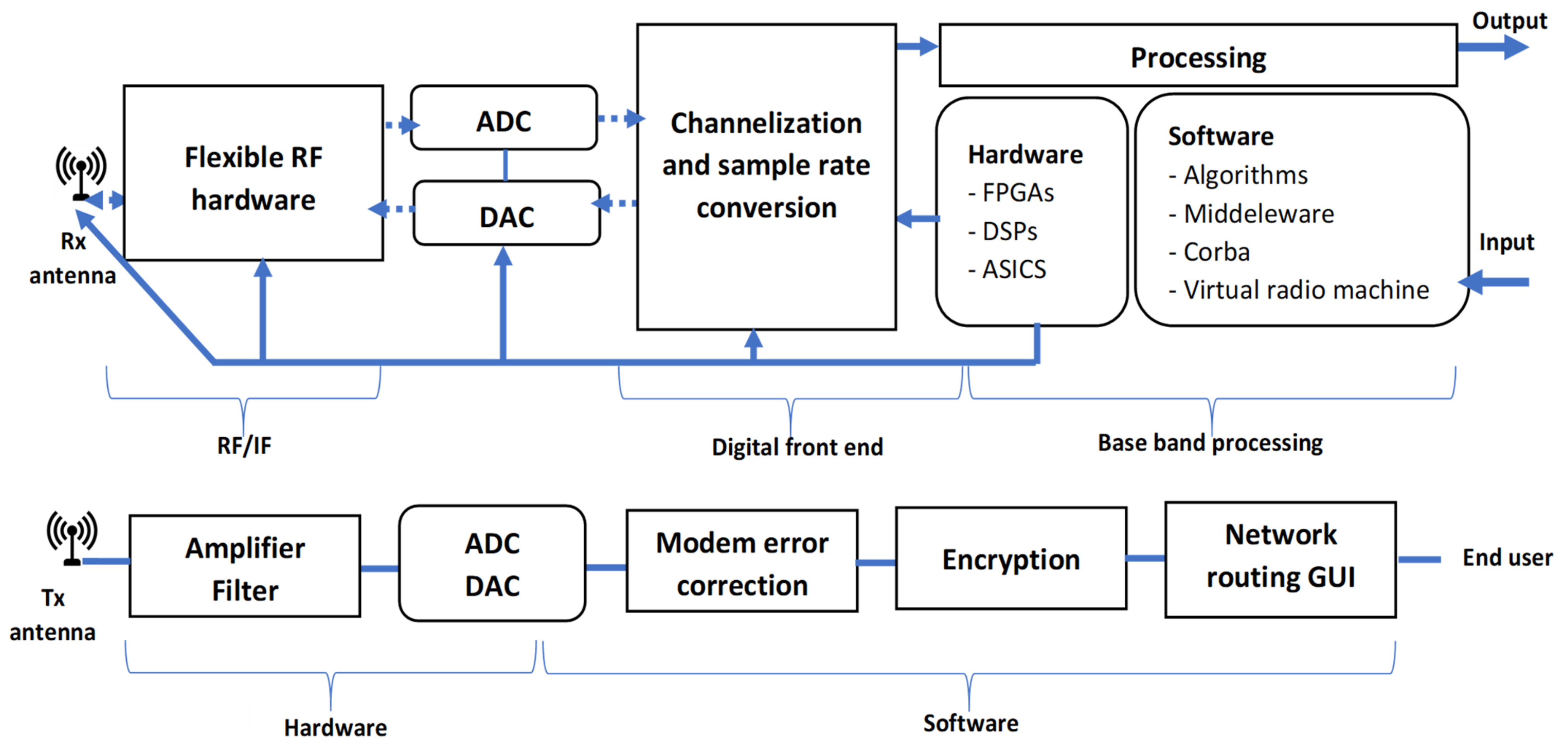
2.2. System-Defined Radio Paradigm (SDR)
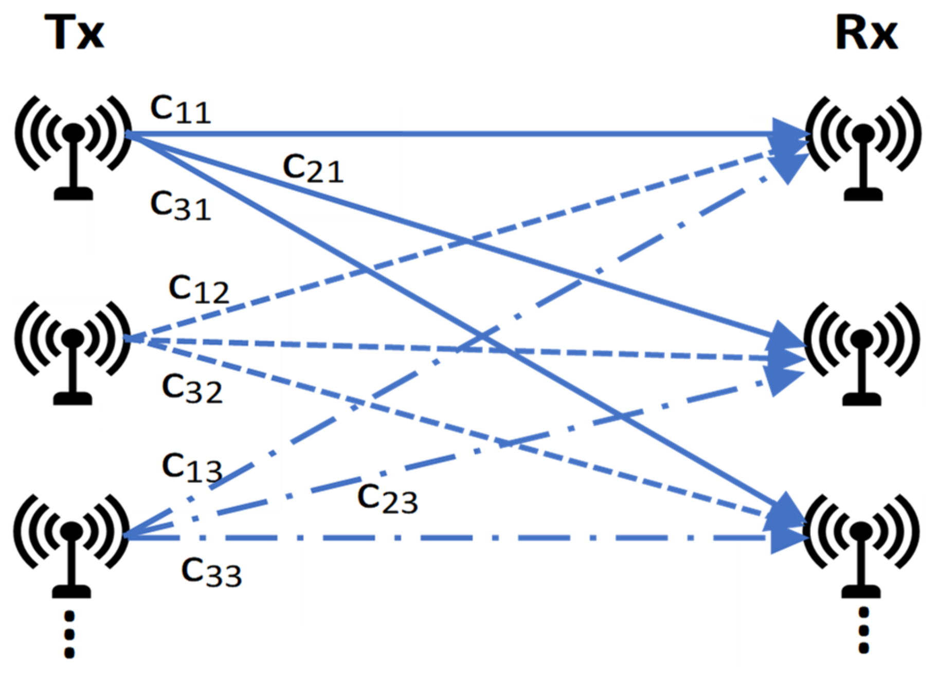
2.3. MIMO Systems
3. State-of-the-Art MIMO-SDR Systems
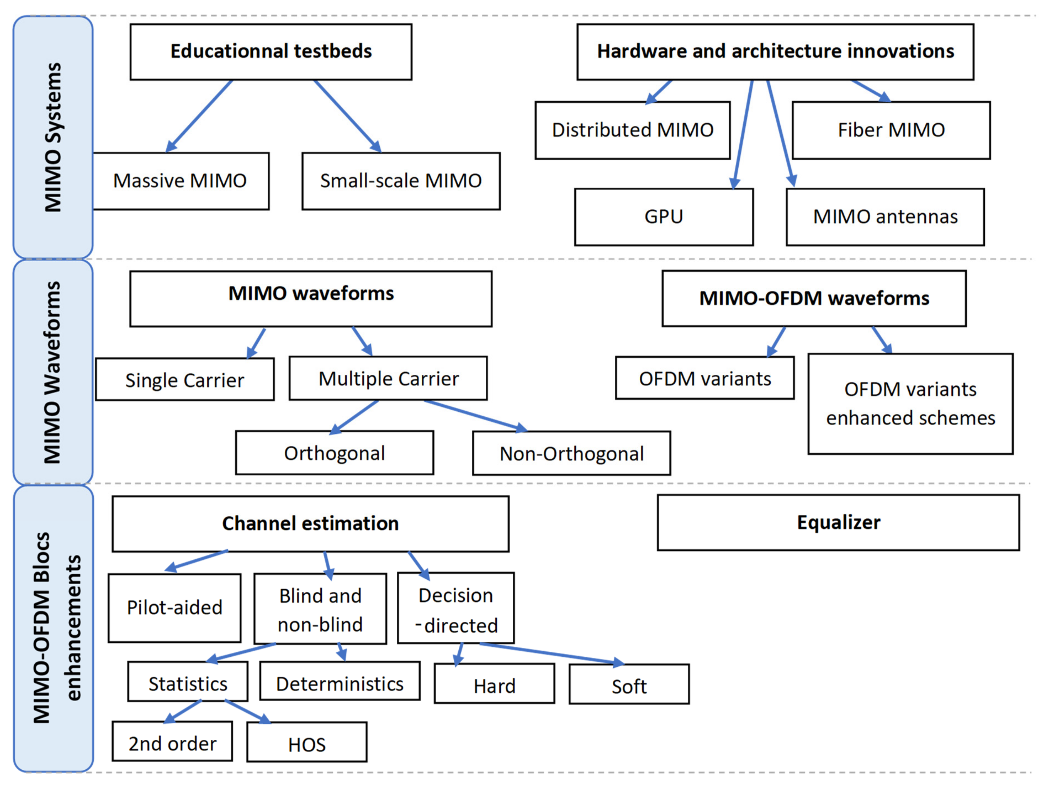
3.1. MIMO Systems
3.1.1. Educational Platforms and Testbeds
Massive MIMO Systems
- It allows the amount of data supported in both the uplink and the downlink to be 384 Gbits/s.
- The synchronization is performed with an external signal derived from 8 Octo-Clock devices (7 Octo-Clock devices commanded with a master Octo-Clock). However, some phase tight distortion appears during the transmission tests performed between the base station radio frequency channels; this is due to the receiver channels [24].
- The system could be extended up to 128 antennas.
- A planar T-shaped antenna array with 160 dual polarized elements was used. Moreover, five USRP-RIO-type 2953Rs are deployed to emulate the receiving user equipment with a GPS reference signal connection capability.
Small-Scale MIMO Systems
3.1.2. Hardware and Architecture Innovations
Distributed MIMO
- Single source transmission: a source (S), generating the signals to be transmitted, is connected via wireless or a physical interface to the non-collocated transmitting antennas. The signal is received, in the other side, by another set of antennas and transmitted to a receiving point (R) that gathers all the information. The signaling channel interfaces are necessary to set up the MIMO communications. Please refer to Figure 5a.
- Cooperative transmission: in this case, each transmitting antenna represents a signal source by itself. The transmitting and receiving antennas can cooperate, using signaling channel information, without the need of an intermediate point. Please refer to Figure 5b.
Fiber-Based Systems
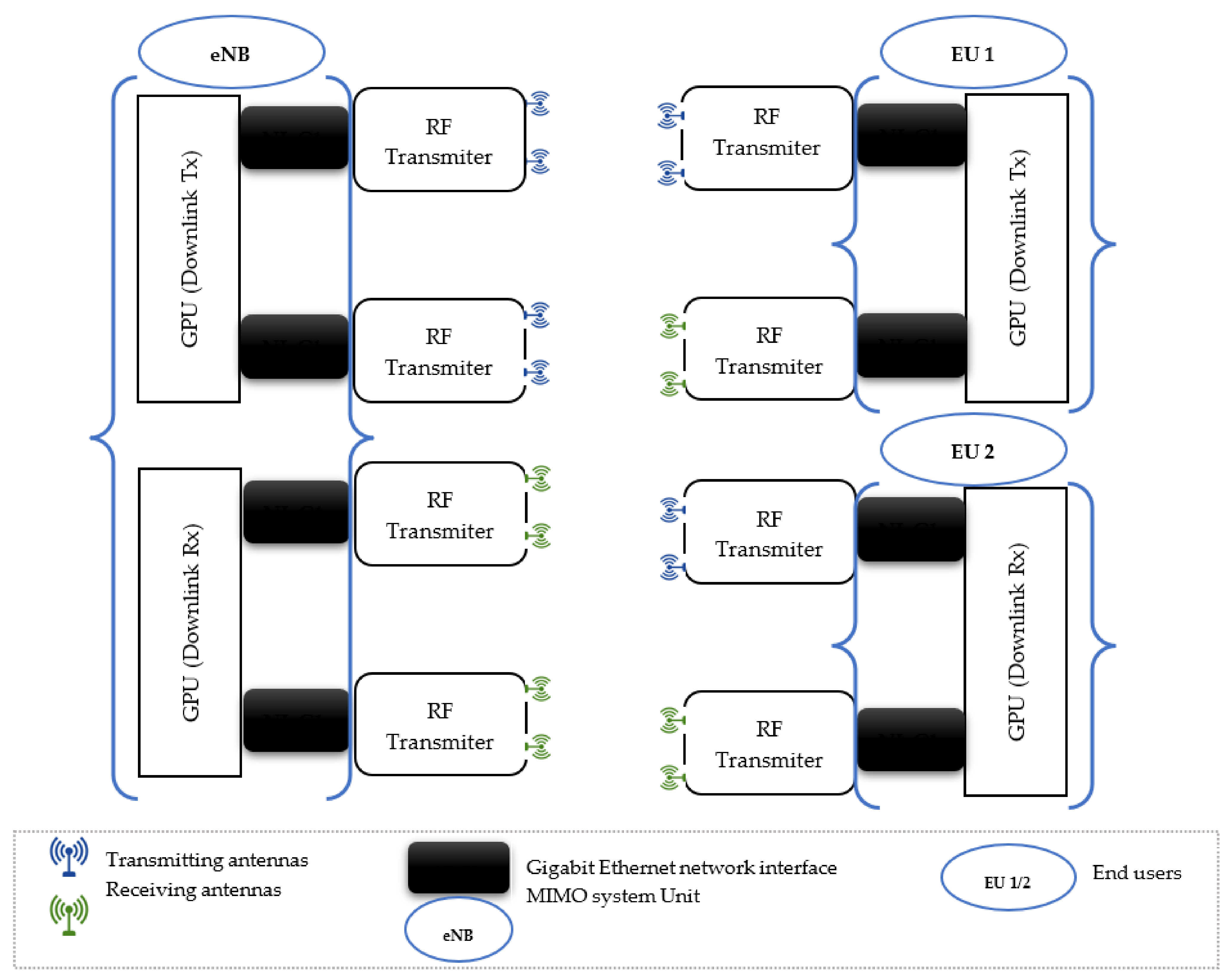
GPU Implementations
MIMO Antennas
- Operability in multi-band frequencies
- Polarization diversity
- Low size and cost with high performance.
3.2. MIMO-SDR Waveforms
3.2.1. MIMO Waveforms Analysis
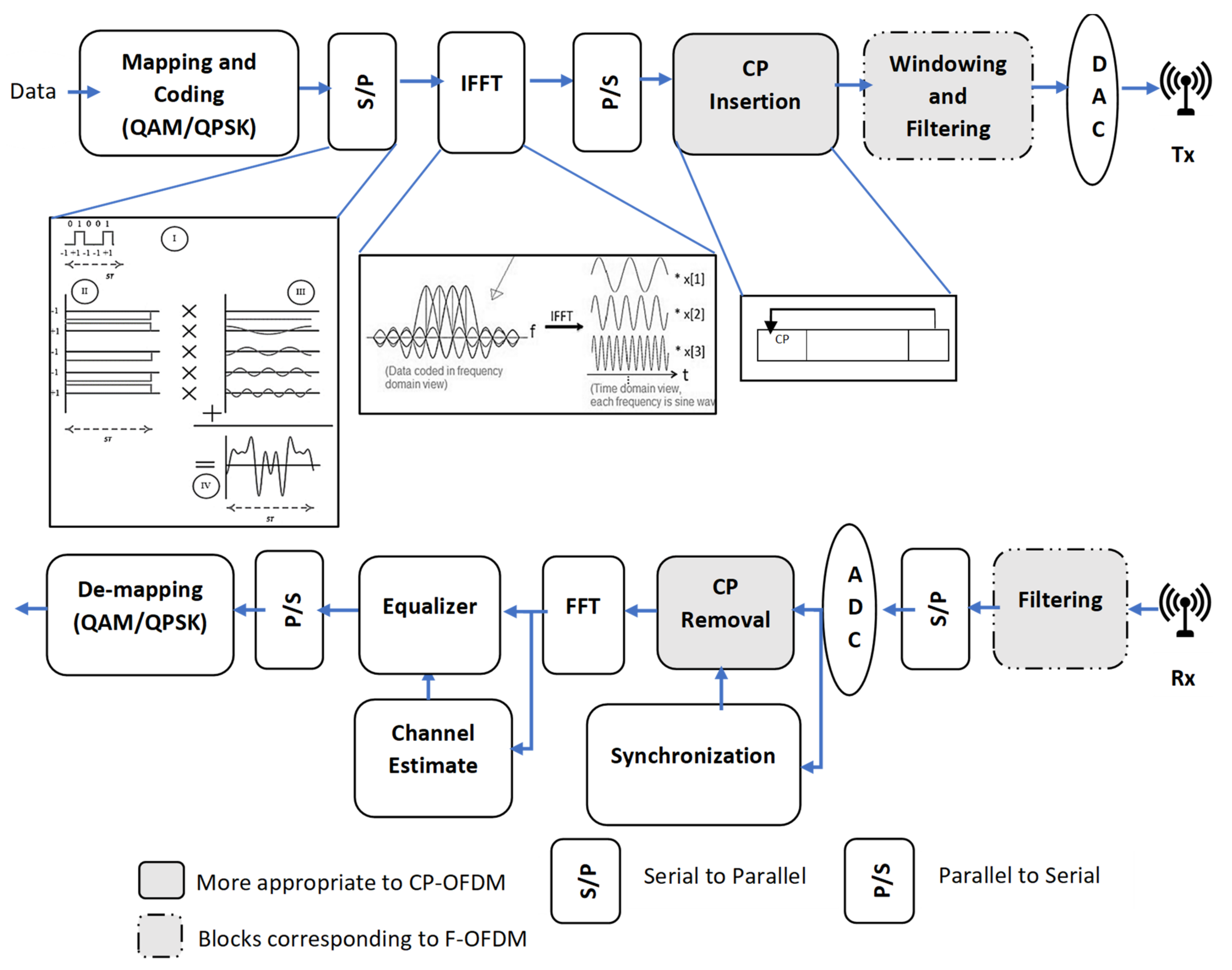
3.2.2. OFDM/Cyclic Prefix OFDM (CP-OFDM) Theory Aspects
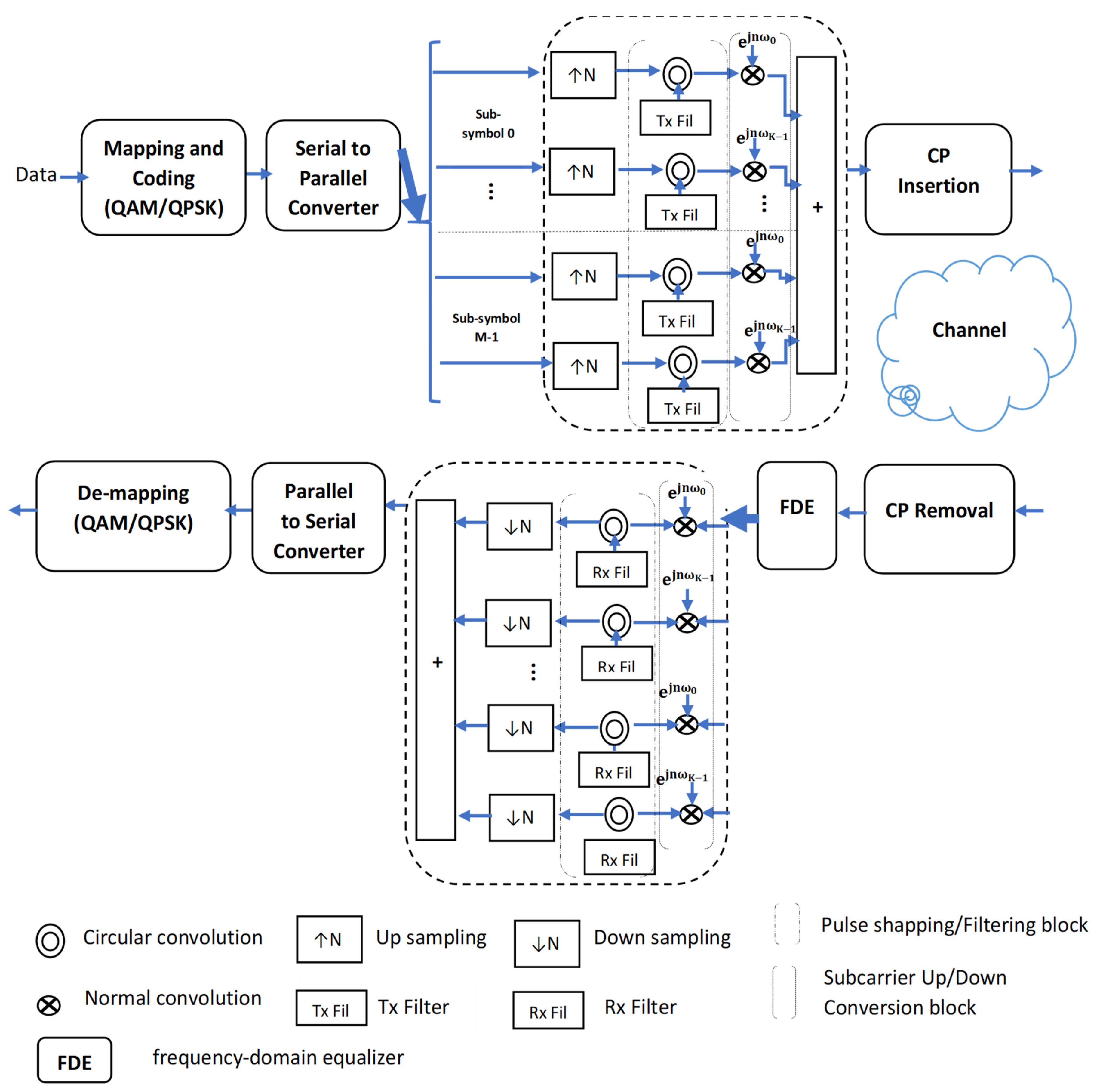
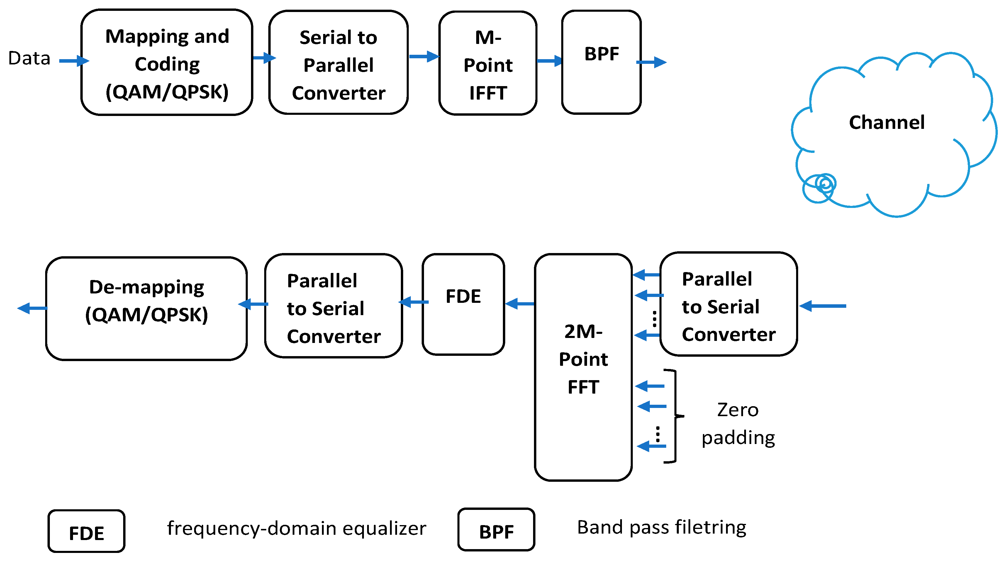
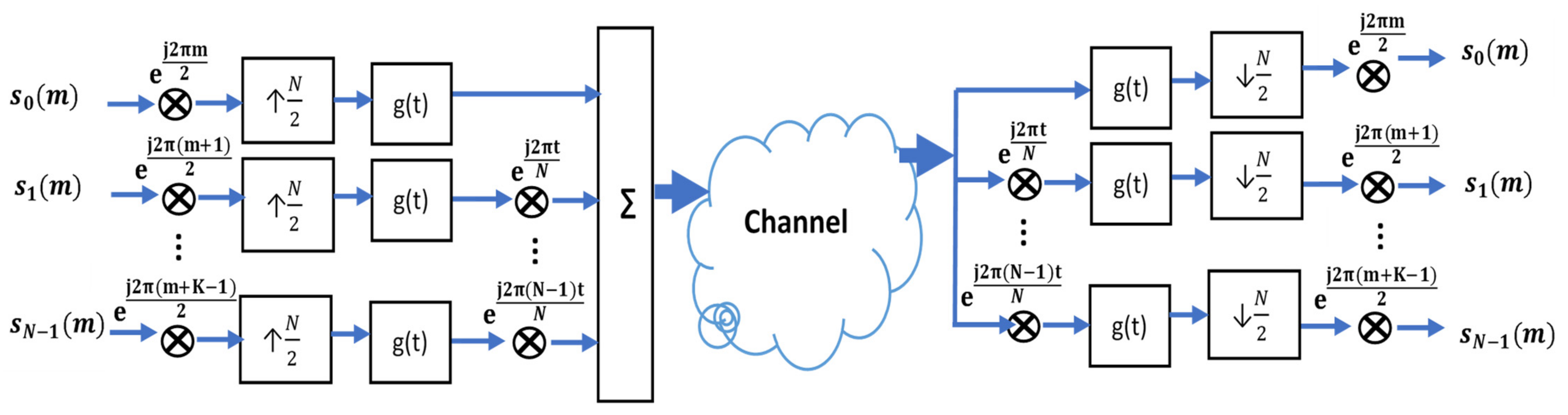
3.2.3. MIMO-OFDM Variants
- GFDM
- UF-OFDM
- FBMC-OQAM
3.2.4. MIMO-OFDM Variants Enhancement Studies
3.3. MIMO-OFDM Block Enhancements
3.3.1. Channel Estimation
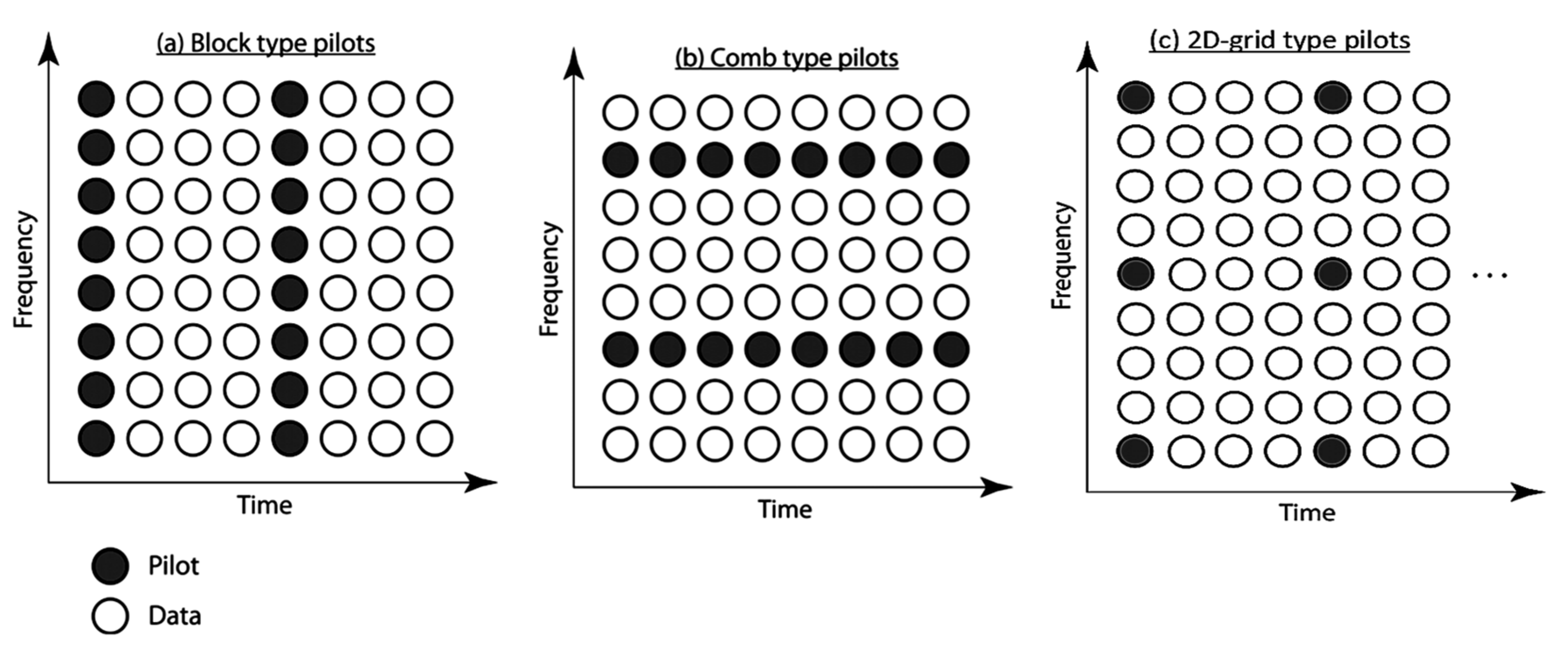
- Pilot-aided channel estimation algorithms
- Blind and semi-blind channel estimation algorithms
- Decision-directed channel estimation algorithms
3.3.2. Equalization
4. Conclusions
- -
- The part on implementation is more limited to research testbeds that apply traditional channel estimation algorithms.
- -
- The most deployed channel estimation algorithms are complex and have a lower level of mitigation of ICI.
- -
- The equalization algorithms are quite limited in terms of performance.
4.1. Challenges
4.2. Opportunities
- -
- The machine learning algorithm, as well as the empirical mode decomposition-based methods, draws interesting results for the channel estimating problem.
- -
- The equalization techniques based on the wavelet decomposition technique are interesting.
- -
- OFDM waveform enhanced schema.
Author Contributions
Funding
Institutional Review Board Statement
Informed Consent Statement
Data Availability Statement
Acknowledgments
Conflicts of Interest
References
- Garcıa-Naya, J.A.; González-López, M.; Castedo, L. An overview of MIMO testbed technology. In Proceedings of the 4th International Symposium on Image and Video Communications over Fixed and Mobile Networks (ISIVC’08), Bilbao, Spain, 9–11 July 2008. [Google Scholar]
- Delson, T.R.; Jose, I. A Survey on 5G Standards, Specifications and Massive MIMO Testbed Including Transceiver Design Models Using QAM Modulation Schemes. In Proceedings of the 2019 International Conference on Data Science and Communication (IconDSC), Bangalore, India, 1–2 March 2019; IEEE: Piscataway, NJ, USA, 2019; pp. 1–7. [Google Scholar]
- Shafi, M.; Molisch, A.F.; Smith, P.J.; Haustein, T.; Zhu, P.; Silva, P.D.; Tufvesson, F.; Benjebbour, A.; Wunder, G. 5G: A Tutorial Overview of Standards, Trials, Challenges, Deployment, and Practice. IEEE J. Sel. Areas Commun. 2017, 35, 1201–1221. [Google Scholar] [CrossRef]
- Banelli, P.; Buzzi, S.; Colavolpe, G.; Modenini, A.; Rusek, F.; Ugolini, A. Modulation Formats and Waveforms for 5G Networks: Who Will Be the Heir of OFDM?: An overview of alternative modulation schemes for improved spectral efficiency. IEEE Signal Process. Mag. 2014, 31, 80–93. [Google Scholar] [CrossRef]
- Wang, C.; Haider, F.; Gao, X.; You, X.; Yang, Y.; Yuan, D.; Aggoune, H.M.; Haas, H.; Fletcher, S.; Hepsaydir, E. Cellular architecture and key technologies for 5G wireless communication networks. IEEE Commun. Mag. 2014, 52, 122–130. [Google Scholar] [CrossRef]
- Amin, M.R.; Trapasiya, S.D. Space Time Coding Scheme for MIMO system-Literature Survey. Procedia Eng. 2012, 38, 3509–3517. [Google Scholar] [CrossRef]
- Chen, S.; Zhang, J.; Zhang, J.; Björnson, E.; Ai, B. A survey on user-centric cell-free massive MIMO systems. Digit. Commun. Netw. 2021, in press. [Google Scholar] [CrossRef]
- Mokhtari, Z.; Sabbaghian, M.; Dinis, R. A Survey on Massive MIMO Systems in Presence of Channel and Hardware Impairments. Sensors 2019, 19, 164. [Google Scholar] [CrossRef]
- Ijiga, O.E.; Ogundile, O.O.; Familua, A.D.; Versfeld, D.J. Review of channel estimation for candidate waveforms of next generation networks. Electronics 2019, 8, 956. [Google Scholar] [CrossRef]
- Wen, F.; Wymeersch, H.; Peng, B.; Tay, W.P.; So, H.C.; Yang, D. A survey on 5G massive MIMO localization. Digit. Signal Process. 2019, 94, 21–28. [Google Scholar] [CrossRef]
- Zheng, K.; Zhao, L.; Mei, J.; Shao, B.; Xiang, W.; Hanzo, L. Survey of Large-Scale MIMO Systems. IEEE Commun. Surv. Tutor. 2015, 17, 1738–1760. [Google Scholar] [CrossRef]
- Yang, S.; Hanzo, L. Fifty Years of MIMO Detection: The Road to Large-Scale MIMOs. IEEE Commun. Surv. Tutor. 2015, 17, 1941–1988. [Google Scholar] [CrossRef]
- Paul, B.S.; Bhattacharjee, R. MIMO channel modeling: A review. IETE Tech. Rev. 2008, 25, 315–319. [Google Scholar] [CrossRef]
- Yu, K.; Ottersten, B. Models for MIMO propagation channels: A review. Wirel. Commun. Mob. Comput. 2002, 2, 653–666. [Google Scholar] [CrossRef]
- Fatema, N.; Hua, G.; Xiang, Y.; Peng, D.; Natgunanathan, I. Massive MIMO Linear Precoding: A Survey. IEEE Syst. J. 2018, 12, 3920–3931. [Google Scholar] [CrossRef]
- Qiao, G.; Babar, Z.; Ma, L.; Ahmed, N. Channel Estimation and Equalization of Underwater Acoustic MIMO-OFDM Systems: A Review Estimation du canal et l’égalisation des systèmes MEMS-MROF acoustiques sous-marins: Une revue. Can. J. Electr. Comput. Eng. 2019, 42, 199–208. [Google Scholar] [CrossRef]
- Fette, B. Introducing Adaptive, Aware, and Cognitive Radios. In Cognitive Radio, Software Defined Radio, and Adaptive Wireless Systems; Arslan, H., Ed.; Springer: Dordrecht, The Netherlands, 2007; pp. 1–16. [Google Scholar]
- Luther, E. 5G massive MIMO testbed: From theory to reality. White Paper. 2014. Available online: https://www.ni.com/en-rs/innovations/white-papers/14/5g-massive-mimo-testbed--from-theory-to-reality--.html (accessed on 4 May 2022).
- Hasan, W.B.; Harris, P.; Doufexi, A.; Beach, M. Real-Time Maximum Spectral Efficiency for Massive MIMO and its Limits. IEEE Access 2018, 6, 46122–46133. [Google Scholar] [CrossRef]
- Zhang, C.; Qiu, R.C. Massive MIMO testbed-implementation and initial results in system model validation. arXiv 2014, arXiv:1501.00035. [Google Scholar]
- Ryan, Ø.; Debbah, M. Random Vandermonde matrices-part I: Fundamental results. IEEE Trans. Inf. Theory 2008, 1, 1–20. [Google Scholar]
- Ryan, Ø.; Debbah, M. Random vandermonde matrices-part ii: Applications. IEEE Trans. Inf. Theory 2008, 1, 1–13. [Google Scholar]
- Vieira, J.; Malkowsky, S.; Nieman, K.; Miers, Z.; Kundargi, N.; Liu, L.; Wong, I.; Öwall, V.; Edfors, O.; Tufvesson, F. A flexible 100-antenna testbed for Massive MIMO. In Proceedings of the 2014 IEEE Globecom Workshops (GC Wkshps), Austin, TX, USA, 8–12 December 2014; IEEE: Piscataway, NJ, USA, 2014; pp. 287–293. [Google Scholar]
- Edfors, O. LuMaMi-A Flexible Testbed for Massive MIMO. Available online: https://people.kth.se/~perz/ewtbwr/2014/abstracts/Edfors.pdf (accessed on 1 March 2022).
- Jiang, X.; Kaltenberger, F. Demo: An LTE compatible massive MIMO testbed based on OpenAirInterface. In Proceedings of the WSA 2017, 21th International ITG Workshop on Smart Antennas, Berlin, Germany, 15–17 March 2017; IEEE: Piscataway, NJ, USA, 2017; pp. 1–2. [Google Scholar]
- Malkowsky, S.; Vieira, J.; Liu, L.; Harris, P.; Nieman, K.; Kundargi, N.; Wong, I.C.; Tufvesson, F.; Öwall, V.; Edfors, O. The World’s First Real-Time Testbed for Massive MIMO: Design, Implementation, and Validation. IEEE Access 2017, 5, 9073–9088. [Google Scholar] [CrossRef]
- Batra, A.; Wiemeler, M.; Kreul, T.; Goehringer, D.; Kaiser, T. A Massive MIMO Signal Processing Architecture for GHz to THz Frequencies. In Proceedings of the 2018 First International Workshop on Mobile Terahertz Systems (IWMTS), Duisburg, Germany, 2–4 July 2018; IEEE: Piscataway, NJ, USA, 2018; pp. 1–6. [Google Scholar]
- Zamfirescu, C.; Vulpe, A.; Halunga, S.; Fratu, O. Spatial Multiplexing MIMO 5G-SDR Open Testbed Implementation. In Proceedings of the International Conference on Future Access Enablers of Ubiquitous and Intelligent Infrastructures, Sofia, Bulgaria, 28–29 March 2019; pp. 197–213. [Google Scholar]
- Ribeiro, C.; Gameiro, A. A software-defined radio FPGA implementation of OFDM-based PHY transceiver for 5G. Analog. Integr. Circuits Signal Process. 2017, 91, 343–351. [Google Scholar] [CrossRef]
- Vielva, L.; Vía, J.; Gutiérrez, J.; González, Ó.; Ibáñez, J.; Santamaría, I. Building a web platform for learning advanced digital communications using a MIMO testbed. In Proceedings of the 2010 IEEE International Conference on Acoustics, Speech and Signal Processing, Dallas, TX, USA, 14–19 March 2010; IEEE: Piscataway, NJ, USA, 2010; pp. 2942–2945. [Google Scholar]
- Naya, J. Testbed Design for Wireless Communications Systems Assessment. Ph.D. Thesis, Universidade Da Coruna, A Coruña, Spain, 2010. [Google Scholar]
- Bates, D.; Henriksen, S.; Ninness, B.; Weller, S.R. A 4× 4 FPGA-based wireless testbed for LTE applications. In Proceedings of the 2008 IEEE 19th International Symposium on Personal, Indoor and Mobile Radio Communications, Cannes, France, 15–18 September 2008; pp. 1–5. [Google Scholar]
- Nieto, X.; Ventura, L.M.; Mollfulleda, A. GEDOMIS: A broadband wireless MIMO-OFDM testbed, design and implementation. In Proceedings of the 2nd International Conference on Testbeds and Research Infrastructures for the Development of Networks and Communities (TRIDENTCOM 2006), Barcelona, Spain, 1–3 March 2006; pp. 10–121. [Google Scholar]
- Ramirez, D.; Santamaria, I.; Pérez, J.; Via, J.; Tazón, A.; Garcia-Naya, J.; Fernández-Caramés, T.; López, M.G.; Perez-Iglesias, H.; Castedo, L. A flexible testbed for the rapid prototyping of MIMO baseband modules. In Proceedings of the 2006 3rd International Symposium on Wireless Communication Systems, Valencia, Spain, 6–8 September 2006; pp. 776–780. [Google Scholar]
- Caban, S.; Mehlführer, C.; Langwieser, R.; Scholtz, A.L.; Rupp, M. Vienna MIMO testbed. EURASIP J. Adv. Signal Process. 2006, 2006, 054868. [Google Scholar] [CrossRef]
- Sundance Multiprocessor Technology, SMT 365. Available online: https://www.sundance.com/product-range/sundance-products/archived-products/smt365-16-1/ (accessed on 1 March 2022).
- Roy, S.; Bélanger, L. The design of an fpga-based mimo transceiver for wi-fi. DSP Mag. 2006, 1, 28–31. [Google Scholar]
- Borkowski, D.; Brühl, L.; Degen, C.; Keusgen, W.; Alirezaei, G.; Geschewski, F.; Oikonomopoulos, C.; Rembold, B. SABA: A testbed for a real-time MIMO system. EURASIP J. Appl. Signal Process. 2006, 2006, 143. [Google Scholar] [CrossRef][Green Version]
- Dowle, J.; Kuo, S.H.; Mehrotra, K.; McLoughlin, I.V. An FPGA-based MIMO and space-time processing platform. EURASIP J. Appl. Signal Process. 2006, 2006, 1–14. [Google Scholar] [CrossRef][Green Version]
- Wilzeck, A.; El-Hadidy, M.; Cai, Q.; Amelingmeyer, M.; Kaiser, T. MIMO prototyping test-bed with off-the-shelf plug-in RF hardware. In Proceedings of the IEEE Workshop on Smart Antennas, Ulm, Germany, 13–14 March 2006. [Google Scholar]
- Zhu, W.; Browne, D.; Fitz, M. An open access wideband multiantenna wireless testbed with remote control capability. In Proceedings of the First International Conference on Testbeds and Research Infrastructures for the DEvelopment of NeTworks and COMmunities, Trento, Italy, 23–25 February 2005; pp. 72–81. [Google Scholar]
- Wallace, J.W.; Jeffs, B.D.; Jensen, M.A. A real-time multiple antenna element testbed for MIMO algorithm development and assessment. In Proceedings of the IEEE Antennas and Propagation Society Symposium, Monterey, CA, USA, 20–25 June 2004; pp. 1716–1719. [Google Scholar]
- Lang, S.; Rao, M.; Daneshrad, B. Design and development of a 5.25 GHz software defined wireless OFDM communication platform. IEEE Commun. Mag. 2004, 42, S6–S12. [Google Scholar] [CrossRef]
- Morawski, R.; Le-Ngoc, T.; Naeem, O. Wireless and wireline MIMO testbed. In Proceedings of the CCECE 2003-Canadian Conference on Electrical and Computer Engineering. Toward a Caring and Humane Technology (Cat. No. 03CH37436), Montreal, QC, Canada, 4–7 May 2003; pp. 1913–1916. [Google Scholar]
- Murphy, P.; Lou, F.; Sabharwal, A.; Frantz, J.P. An FPGA based rapid prototyping platform for MIMO systems. In Proceedings of the The Thrity-Seventh Asilomar Conference on Signals, Systems & Computers, Pacific Grove, CA, USA, 9–12 November 2003; pp. 900–904. [Google Scholar]
- Fabregas, A.G.; Guillaud, M.; Caire, G.; Gosse, K.; Rouquette, S.; Dias, A.R.; Bernardin, P.; Miet, X.; Conrat, J.-M.; Toutain, Y. A MIMO-OFDM testbed for wireless local area networks. In Proceedings of the Conference Record of the Thirty-Ninth Asilomar Conference onSignals, Systems and Computers, Pacific Grove, CA, USA, 30 October–2 November 2005; pp. 82–86. [Google Scholar]
- Sezgin, I.C.; Dahlgren, M.; Eriksson, T.; Coldrey, M.; Larsson, C.; Gustavsson, J.; Fager, C. A Low-Complexity Distributed-MIMO Testbed Based on High-Speed Sigma–Delta-Over-Fiber. IEEE Trans. Microw. Theory Tech. 2019, 67, 2861–2872. [Google Scholar] [CrossRef]
- Simeone, O.; Somekh, O.; Poor, H.V.; Shamai, S. Distributed MIMO Systems for Nomadic Applications Over a Symmetric Interference Channel. IEEE Trans. Inf. Theory 2009, 55, 5558–5574. [Google Scholar] [CrossRef]
- Kun, Z.; Crisp, M.J.; Sailing, H.; Penty, R.V.; White, I.H. MIMO system capacity improvements using radio-over-fibre distributed antenna system technology. In Proceedings of the 2011 Optical Fiber Communication Conference and Exposition and the National Fiber Optic Engineers Conference, Los Angeles, CA, USA, 6–10 March 2011; IEEE: Piscataway, NJ, USA, 2011; pp. 1–3. [Google Scholar]
- Gordon, G.S.D.; Crisp, M.J.; Penty, R.V.; White, I.H. Experimental Evaluation of Layout Designs for 3 × 3 MIMO-Enabled Radio-Over-Fiber Distributed Antenna Systems. IEEE Trans. Veh. Technol. 2014, 63, 643–653. [Google Scholar] [CrossRef]
- Ahn, C.; Kim, J.; Ju, J.; Choi, J.; Choi, B.; Choi, S. Implementation of an SDR platform using GPU and its application to a 2 × 2 MIMO WiMAX system. Analog. Integr. Circuits Signal Process. 2011, 69, 107. [Google Scholar] [CrossRef]
- Han, S.W.; Jin, Y.; Ahn, H.S.; Choi, S.W.; Hyeon, S.H. Implementation of an MU-MIMO system with GPU modem for non-codebook-based TDD LTE-A. In Proceedings of the The 18th IEEE International Symposium on Consumer Electronics (ISCE 2014), Jeju, Korea, 22–25 June 2014; IEEE: Piscataway, NJ, USA, 2014; pp. 1–2. [Google Scholar]
- Roger, S.; Ramiro, C.; Gonzalez, A.; Almenar, V.; Vidal, A.M. Fully Parallel GPU Implementation of a Fixed-Complexity Soft-Output MIMO Detector. IEEE Trans. Veh. Technol. 2012, 61, 3796–3800. [Google Scholar] [CrossRef]
- Wu, M.; Sun, Y.; Gupta, S.; Cavallaro, J.R. Implementation of a High Throughput Soft MIMO Detector on GPU. J. Signal Process. Syst. 2011, 64, 123–136. [Google Scholar] [CrossRef][Green Version]
- Gokalgandhi, B.; Segerholm, C.; Paul, N.; Seskar, I. Accelerating Channel Estimation and Demodulation of Uplink OFDM symbols for Large Scale Antenna Systems using GPU. In Proceedings of the 2019 International Conference on Computing, Networking and Communications (ICNC), Honolulu, HI, USA, 18–21 February 2019; IEEE: Piscataway, NJ, USA, 2019; pp. 955–959. [Google Scholar]
- Caire, G.; Taricco, G.; Biglieri, E. Bit-interleaved coded modulation. IEEE Trans. Inf. Theory 1998, 44, 927–946. [Google Scholar] [CrossRef]
- Raychaudhuri, D.; Seskar, I.; Ott, M.; Ganu, S.; Ramachandran, K.; Kremo, H.; Siracusa, R.; Liu, H.; Singh, M. Overview of the ORBIT radio grid testbed for evaluation of next-generation wireless network protocols. In Proceedings of the IEEE Wireless Communications and Networking Conference, Wuhan, China, 23–26 September 2005; pp. 1664–1669. [Google Scholar]
- Bhagavatula, R.; Heath, R.W., Jr.; Linehan, K. Performance evaluation of MIMO base station antenna designs. Antenna Syst. Technol. Mag. 2008, 11, 14–17. [Google Scholar]
- Li, Y.; Luo, Y.; Yang, G. High-Isolation 3.5 GHz Eight-Antenna MIMO Array Using Balanced Open-Slot Antenna Element for 5G Smartphones. IEEE Trans. Antennas Propag. 2019, 67, 3820–3830. [Google Scholar] [CrossRef]
- Kamran Shereen, M.; Khattak, M.I.; Witjaksono, G. A brief review of frequency, radiation pattern, polarization, and compound reconfigurable antennas for 5G applications. J. Comput. Electron. 2019, 18, 1065–1102. [Google Scholar] [CrossRef]
- Ojaroudi Parchin, N.; Jahanbakhsh Basherlou, H.; Al-Yasir, Y.I.; Abd-Alhameed, R.A.; Abdulkhaleq, A.M.; Noras, J.M. Recent developments of reconfigurable antennas for current and future wireless communication systems. Electronics 2019, 8, 128. [Google Scholar] [CrossRef]
- Hussain, R.; Sharawi, M.S. A Cognitive Radio Reconfigurable MIMO and Sensing Antenna System. IEEE Antennas Wirel. Propag. Lett. 2015, 14, 257–260. [Google Scholar] [CrossRef]
- Hussain, R.; Sharawi, M.S. Integrated reconfigurable multiple-input–multiple-output antenna system with an ultra-wideband sensing antenna for cognitive radio platforms. IET Microw. Antennas Propag. 2015, 9, 940–947. [Google Scholar] [CrossRef]
- Kambali, V.; Abegaonkar, M.; Basu, A. Frequency reconfigurable compact MIMO antenna for WLAN application. In Proceedings of the 2017 International Symposium on Antennas and Propagation (ISAP), Phuket, Thailand, 30 October–2 November 2017; pp. 1–2. [Google Scholar]
- Kotwalla, A.; Choukiker, Y.K. Design and analysis of microstrip antenna with frequency reconfigurable in MIMO environment. In Proceedings of the 2017 International conference of Electronics, Communication and Aerospace Technology (ICECA), Coimbatore, India, 20–22 April 2017; pp. 354–358. [Google Scholar]
- Thao, H.T.P.; Luan, V.T.; Minh, N.C.; Journet, B.; Van Yem, V. A company frequency reconfigurable MIMO antenna with low mutual coupling for UMTS and LTE applications. In Proceedings of the 2017 International Conference on Advanced Technologies for Communications (ATC), Quy Nhon, Vietnam, 18–20 October 2017; pp. 174–179. [Google Scholar]
- Duyen, T.H.; Pham, A.T. Performance analysis of mimo/fso systems using sc-qam signaling over atmospheric turbulence channels. IEICE Trans. Fundam. Electron. Commun. Comput. Sci. 2014, 97, 49–56. [Google Scholar] [CrossRef]
- Cai, Q.; Wilzeck, A.; Kaiser, T. Evaluation of Synchronization andl Fractilonally Spaced Equalilzation in a MIMO SC-FDE Test-Bed. In Proceedings of the 2007 IEEE Radio and Wireless Symposium, Long Beach, CA, USA, 9–11 January 2007; pp. 527–530. [Google Scholar]
- Wu, P.; Schober, R.; Bhargava, V.K. Optimal Tx-BF for MIMO SC-FDE Systems. IEEE Commun. Lett. 2013, 17, 1509–1512. [Google Scholar] [CrossRef]
- Mokhtari, Z.; Sabbaghian, M.; Dinis, R. Massive MIMO downlink based on single carrier frequency domain processing. IEEE Trans. Commun. 2016, 66, 1164–1175. [Google Scholar] [CrossRef]
- Nam, Y.-H.; Han, J.-K.; Zhang, J. Multiplexing of control and data in UL MIMO system based on SC-FDM. Patent No. CA2809325A, 1 March 2013. [Google Scholar]
- Berardinelli, G.; de Temino, L.A.M.R.; Frattasi, S.; Sørensen, T.B.; Mogensen, P.E.; Pajukoski, K. On the Feasibility of Precoded Single User MIMO for LTE-A Uplink. JCM 2009, 4, 155–163. [Google Scholar] [CrossRef]
- Priyanto, B.E.; Codina, H.; Rene, S.; Sorensen, T.B.; Mogensen, P. Initial performance evaluation of DFT-spread OFDM based SC-FDMA for UTRA LTE uplink. In Proceedings of the 2007 IEEE 65th Vehicular Technology Conference-VTC2007-Spring, Dublin, Ireland, 22–25 April 2007; pp. 3175–3179. [Google Scholar]
- Torres, P.; Gusmao, A. Detection issues with many BS antennas available for bandwidth-efficient uplink transmission in a MU-MIMO system. In Proceedings of the 2016 IEEE Wireless Communications and Networking Conference, Doha, Qatar, 3–6 April 2016; pp. 1–6. [Google Scholar]
- Sun, Y.; Wang, J.; He, L.; Song, J. Spectral efficiency analysis for spatial modulation in massive MIMO uplink over dispersive channels. In Proceedings of the 2017 IEEE International Conference on Communications (ICC), Paris, France, 21–25 May 2017; pp. 1–6. [Google Scholar]
- De Temiño, L.Á.M.R.; Berardinelli, G.; Frattasi, S.; Pajukoski, K.; Mogensen, P. Single-user MIMO for LTE-A uplink: Performance evaluation of OFDMA vs. SC-FDMA. In Proceedings of the 2009 IEEE Radio and Wireless Symposium, San Diego, CA, USA, 18–22 January 2009; pp. 304–307. [Google Scholar]
- Berardinelli, G.; de Temino, L.A.M.R.; Frattasi, S.; Rahman, M.I.; Mogensen, P. OFDMA vs. SC-FDMA: Performance comparison in local area IMT-A scenarios. IEEE Wirel. Commun. 2008, 15, 64. [Google Scholar] [CrossRef]
- Yang, H. A road to future broadband wireless access: MIMO-OFDM-based air interface. IEEE Commun. Mag. 2005, 43, 53–60. [Google Scholar] [CrossRef]
- Clerckx, B.; Joudeh, H.; Hao, C.; Dai, M.; Rassouli, B. Rate splitting for MIMO wireless networks: A promising PHY-layer strategy for LTE evolution. IEEE Commun. Mag. 2016, 54, 98–105. [Google Scholar] [CrossRef]
- Qualcomm Technologies, I. 5G Waveform & Multiple Access Techniques. Available online: https://www.qualcomm.com/media/documents/files/5g-research-on-waveform-and-multiple-access-techniques.pdf (accessed on 1 March 2022).
- Rammyaa, B.; Vishvaksenan, K.S.; Poobal, S.; Krishnan, M.M.M. Coded downlink MIMO MC-CDMA system for cognitive radio network: Performance results. Clust. Comput. 2018, 22, 8371–8378. [Google Scholar] [CrossRef]
- Han, S.; Guo, C.; Meng, W.; Li, C.; Cui, Y.; Tang, W. The uplink and downlink design of MIMO-SCMA system. In Proceedings of the 2016 International Wireless Communications and Mobile Computing Conference (IWCMC), Paphos, Cyprus, 5–9 September 2016; pp. 56–60. [Google Scholar]
- Hadjer, B.; Abdelhafid, B. Comparison & Performance Evaluation of MIMO-FBMC and MIMO-UFMC systems for various equalization techniques. In Proceedings of the 2019 International Conference on Networking and Advanced Systems (ICNAS), Annaba, Algeria, 26–27 June 2019; pp. 1–5. [Google Scholar]
- Zayani, R.; Shaiek, H.; Cheng, X.; Fu, X.; Alexandre, C.; Roviras, D. Experimental Testbed of post-OFDM Waveforms Toward Future Wireless Networks. IEEE Access 2018, 6, 67665–67680. [Google Scholar] [CrossRef]
- Mauricio, W.V.; Araujo, D.C.; Neto, F.H.C.; Lima, F.R.M.; Maciel, T.F. A Low Complexity Solution for Resource Allocation and SDMA Grouping in Massive MIMO Systems. In Proceedings of the 2018 15th International Symposium on Wireless Communication Systems (ISWCS), Lisbon, Portugal, 28–31 August 2018; pp. 1–6. [Google Scholar]
- Wu, S.; Zuo, R.; Zhang, W.; Song, Y. Successive-Parallel Interference Cancellation Multi-user Detection Algorithm for MUSA Uplink. In Wireless and Satellite Systems, Proceedings of the 10th EAI International Conference, WiSATS 2019, Harbin, China, 12–13 January 2019; Springer: Cham, Switzerland, 2019; pp. 541–551. [Google Scholar]
- Ding, Z.; Schober, R.; Poor, H.V. A General MIMO Framework for NOMA Downlink and Uplink Transmission Based on Signal Alignment. IEEE Trans. Wirel. Commun. 2016, 15, 4438–4454. [Google Scholar] [CrossRef]
- Zayani, R.; Medjahdi, Y.; Shaiek, H.; Roviras, D. WOLA-OFDM: A potential candidate for asynchronous 5G. In Proceedings of the 2016 IEEE Globecom Workshops (GC Wkshps), Washington, DC, USA, 4–8 December 2016; pp. 1–5. [Google Scholar]
- Ahmed, R.; Schaich, F.; Wild, T. OFDM Enhancements for 5G Based on Filtering and Windowing. In Multiple Access Techniques for 5G Wireless Networks and Beyond; Springer: Berlin/Heidelberg, Germany, 2019; pp. 39–61. [Google Scholar]
- Jiang, T.; Chen, D.; Ni, C.; Qu, D. (Eds.) Chapter 1—Introduction. In OQAM/FBMC for Future Wireless Communications; Academic Press: Cambridge, MA, USA, 2018; pp. 1–24. [Google Scholar]
- Goztepe, C.; Kurt, G.K. The impact of out of band emissions: A measurement based performance comparison of UF-OFDM and CP-OFDM. Phys. Commun. 2019, 33, 78–89. [Google Scholar] [CrossRef]
- Chen, X.; Zhang, S.; Zhang, A. On MIMO-UFMC in the Presence of Phase Noise and Antenna Mutual Coupling. Radio Sci. 2017, 52, 1386–1394. [Google Scholar] [CrossRef]
- Danneberg, M.; Michailow, N.; Gaspar, I.; Matthé, M.; Dan, Z.; Mendes, L.L.; Fettweis, G. Implementation of a 2 by 2 MIMO-GFDM transceiver for robust 5G networks. In Proceedings of the 2015 International Symposium on Wireless Communication Systems (ISWCS), Brussels, Belgium, 25–28 August 2015; IEEE: Piscataway, NJ, USA, 2015; pp. 236–240. [Google Scholar]
- Zhang, W.; Zhang, Z.; Qi, L.; Dou, Z. Lattice-reduction-aided signal detection in spatial multiplexing MIMO–GFDM systems. Phys. Commun. 2019, 33, 71–77. [Google Scholar] [CrossRef]
- Pereira de Figueiredo, F.A.; Aniceto, N.F.; Seki, J.; Moerman, I.; Fraidenraich, G. Comparing f-OFDM and OFDM Performance for MIMO Systems Considering a 5G Scenario. In Proceedings of the 5GWF2019, the the 2019 IEEE 2nd 5G World Forum, Dresden, Germany, 30 September–2 October 2019; pp. 1–6. [Google Scholar]
- Caus, M.; Pérez-Neira, A.I. Transmitter-receiver designs for highly frequency selective channels in MIMO FBMC systems. IEEE Trans. Signal Process. 2012, 60, 6519–6532. [Google Scholar] [CrossRef]
- Delmade, A.; Browning, C.; Farhang, A.; Marchetti, N.; Doyle, L.E.; Koilpillai, R.D.; Barry, L.P.; Venkitesh, D. Performance analysis of analog IF over fiber fronthaul link with 4G and 5G coexistence. J. Opt. Commun. Netw. 2018, 10, 174–182. [Google Scholar] [CrossRef]
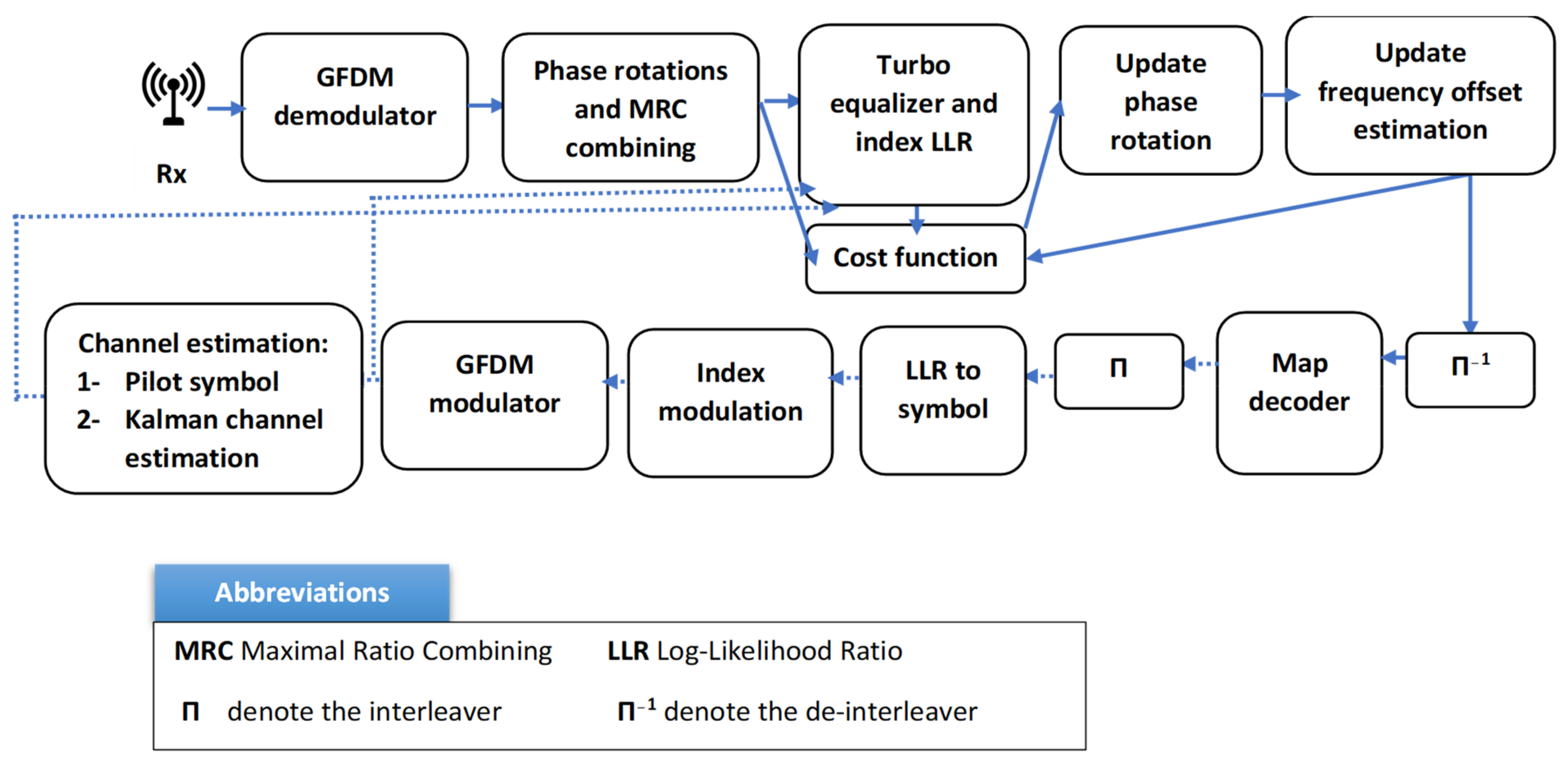
- Chang, Y.-K.; Ueng, F.-B. A novel turbo GFDM-IM receiver for MIMO communications. AEU Int. J. Electron. Commun. 2018, 87, 22–32. [Google Scholar] [CrossRef]
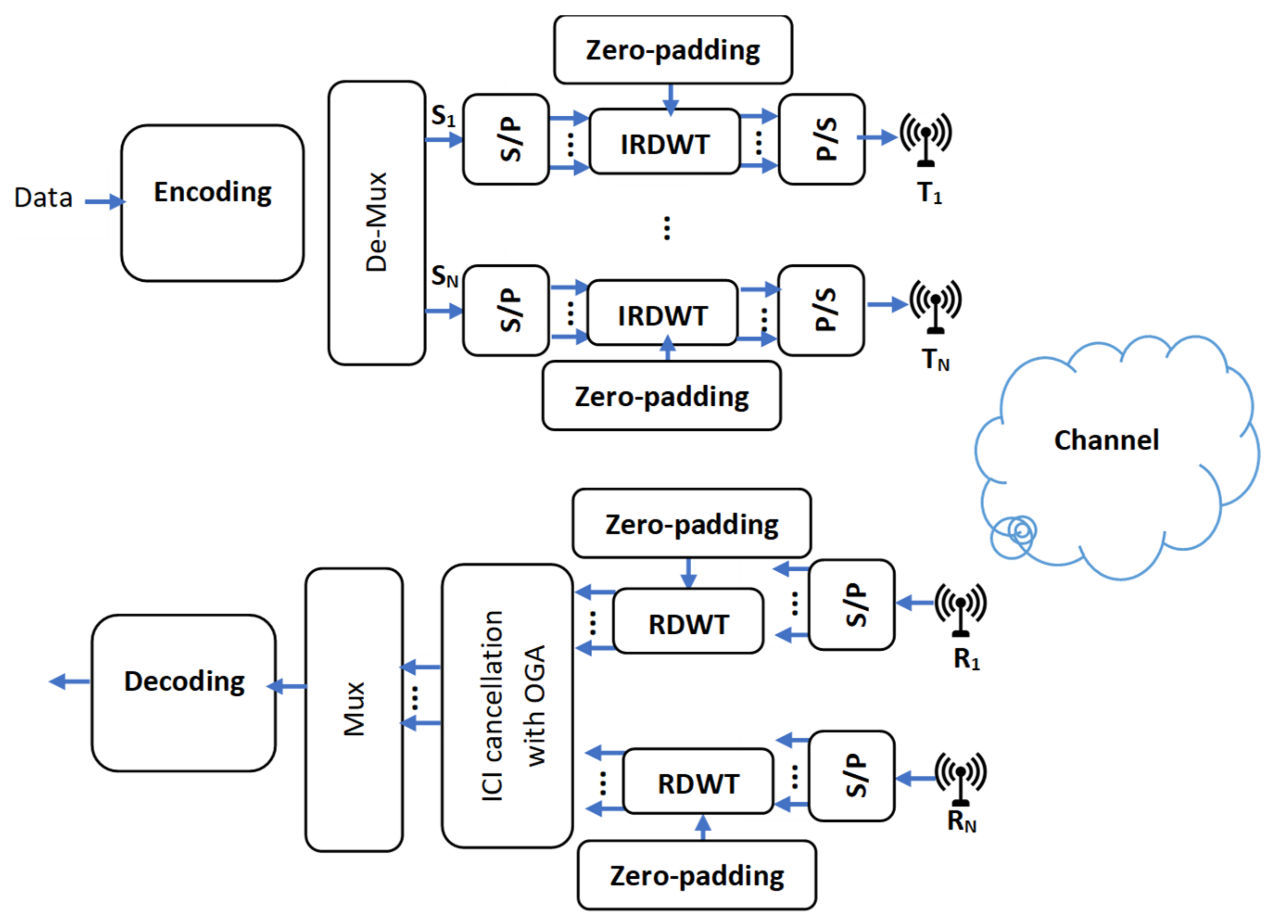
- Sharief, A.H.; Sairam, M.S. Performance analysis of MIMO-RDWT-OFDM system with optimal genetic algorithm. AEU Int. J. Electron. Commun. 2019, 111, 152912. [Google Scholar] [CrossRef]
- Singh, A.; Naik, K.K.; Kumar, C.R.S. NOMURA: A Spectrally Efficient Non-orthogonal 5G Multiple Access Downlink Scheme for Cognitive Radio. IETE Tech. Rev. 2018, 37, 1–10. [Google Scholar] [CrossRef]
- Zakaria, R.; Le Ruyet, D. A novel filter-bank multicarrier scheme to mitigate the intrinsic interference: Application to MIMO systems. IEEE Trans. Wirel. Commun. 2012, 11, 1112–1123. [Google Scholar] [CrossRef]
- Zhao, Z.; Gong, X.; Schellmann, M. A Novel FBMC/OQAM Scheme Facilitating MIMO FDMA without the Need for Guard Bands. In Proceedings of the WSA 2016 20th International ITG Workshop on Smart Antennas, Munich, Germany, 9–11 March 2016; pp. 1–5. [Google Scholar]
- Yu, X.; Guanghui, Y.; Xiao, Y.; Zhen, Y.; Jun, X.; Bo, G. FB-OFDM: A novel multicarrier scheme for 5G. In Proceedings of the 2016 European Conference on Networks and Communications (EuCNC), Athens, Greece, 27–30 June 2016; pp. 271–276. [Google Scholar]
- Jin, C.; Hu, S.; Huang, Y.; Li, F.; Zhang, J.; Ma, S. On design of conjugated transmission scheme for FBMC/OQAM systems with interference cancellation. China Commun. 2017, 14, 166–175. [Google Scholar] [CrossRef]
- Aminjavaheri, A.; Farhang, A.; Rezazadehreyhani, A.; Doyle, L.E.; Farhang-Boroujeny, B. OFDM without CP in massive MIMO. IEEE Trans. Wirel. Commun. 2017, 16, 7619–7633. [Google Scholar] [CrossRef]
- Pereira, A.; Bento, P.; Gomes, M.; Dinis, R.; Silva, V. TIBWB-OFDM: A Promising Modulation Technique for MIMO 5G Transmissions. In Proceedings of the 2018 IEEE 88th Vehicular Technology Conference (VTC-Fall), Chicago, IL, USA, 27–30 August 2018; IEEE: Piscataway, NJ, USA, 2018; pp. 1–5. [Google Scholar]
- Başar, E.; Ü, A.; Panayırcı, E.; Poor, H.V. Orthogonal Frequency Division Multiplexing With Index Modulation. IEEE Trans. Signal Process. 2013, 61, 5536–5549. [Google Scholar] [CrossRef]
- Tarrab, M.; Feuer, A. Convergence and performance analysis of the normalized LMS algorithm with uncorrelated Gaussian data. IEEE Trans. Inf. Theory 1988, 34, 680–691. [Google Scholar] [CrossRef]
- Simon, E.P.; Khalighi, M.A. Iterative soft-Kalman channel estimation for fast time-varying MIMO-OFDM channels. IEEE Wirel. Commun. Lett. 2013, 2, 599–602. [Google Scholar] [CrossRef]
- Kim, K.; Kalantarova, N.; Kozat, S.S.; Singer, A.C. Linear MMSE-optimal turbo equalization using context trees. IEEE Trans. Signal Process. 2013, 61, 3041–3055. [Google Scholar] [CrossRef]
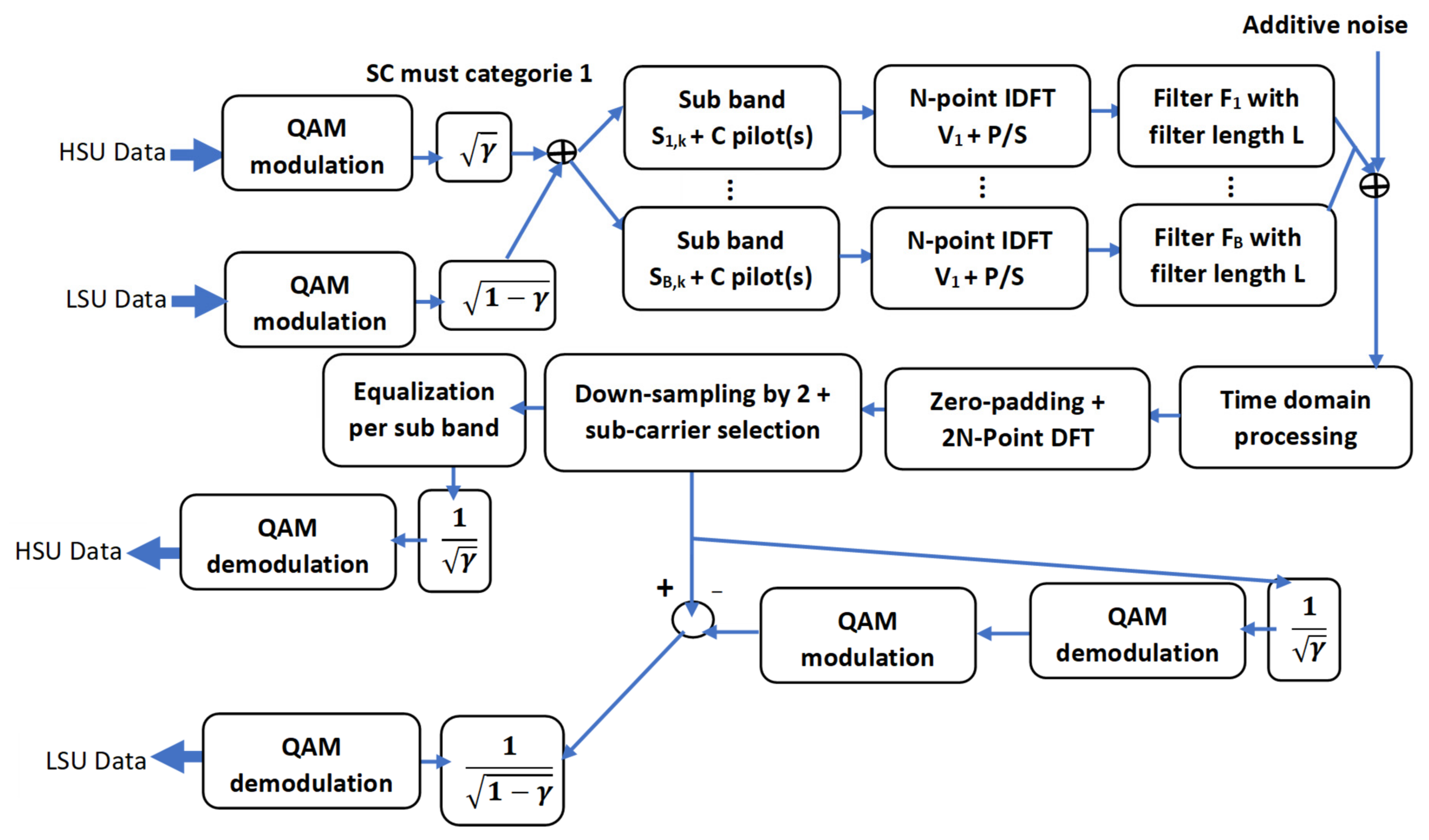
- Meredith, J.M. Study on downlink multiuser superposition transmission for LTE. In Proceedings of the TSG RAN Meeting, Tokyo, Japan, 9–11 March 2015. [Google Scholar]
- Tseng, C.; Cheng, Y.; Chung, C. Subspace-Based Blind Channel Estimation for OFDM by Exploiting Cyclic Prefix. IEEE Wirel. Commun. Lett. 2013, 2, 691–694. [Google Scholar] [CrossRef]
- Yin, C.; Li, J.; Hou, X.; Yue, G. Pilot aided LS channel estimation in MIMO-OFDM systems. In Proceedings of the 2006 8th International Conference on Signal Processing, Guilin, China, 16–20 November 2006. [Google Scholar]
- He, C.; Tian, C.; Li, X.; Zhang, C.; Zhang, S.; Liu, C. A channel estimation scheme for MIMO-OFDM systems. J. Phys. Conf. Ser. 2017, 887, 012039. [Google Scholar] [CrossRef]
- Tang, R.; Zhou, X.; Wang, C. Singular Value Decomposition Channel Estimation in STBC MIMO-OFDM System. Appl. Sci. 2019, 9, 3067. [Google Scholar] [CrossRef]
- Li, W.; Wang, X.; Gu, P.; Wang, D. Research on Channel Estimation of MIMO–OFDM System. In Informatics and Management Science III; Springer: Berlin/Heidelberg, Germany, 2013; pp. 67–73. [Google Scholar]
- Zheng, K.; Su, J.; Wang, W. Iterative DFT-based Channel Estimation for MIMO-OFDM Systems. In Proceedings of the 2006 International Conference on Communications, Circuits and Systems, Hangzhou, China, 25–28 June 2006; IEEE: Piscataway, NJ, USA, 2006; pp. 1081–1085. [Google Scholar]
- Sure, P.; Bhuma, C.M. A pilot aided channel estimator using DFT based time interpolator for massive MIMO-OFDM systems. AEU Int. J. Electron. Commun. 2015, 69, 321–327. [Google Scholar] [CrossRef]
- Dai, L.; Wang, Z.; Yang, Z. Spectrally efficient time-frequency training OFDM for mobile large-scale MIMO systems. IEEE J. Sel. Areas Commun. 2013, 31, 251–263. [Google Scholar] [CrossRef]
- Carbonelli, C.; Franz, S. Performance analysis of MIMO OFDM ML detection in the presence of channel estimation error. In Proceedings of the 2008 IEEE 10th International Symposium on Spread Spectrum Techniques and Applications, Bologna, Italy, 25–28 August 2008; pp. 692–697. [Google Scholar]
- Hlaing, M.; Al-Dhahir, N.; Yinghui, L. Optimal training signals for MIMO OFDM channel estimation in the presence of frequency offset and phase noise. IEEE Trans. Commun. 2006, 54, 1754–1759. [Google Scholar] [CrossRef]
- Hardjawana, W.; Li, R.; Vucetic, B.; Li, Y.; Yang, X. A new iterative channel estimation for high mobility MIMO-OFDM systems. In Proceedings of the 2010 IEEE 71st Vehicular Technology Conference, Taipei, Taiwan, 16–19 May 2010; pp. 1–5. [Google Scholar]
- Mishra, A.; Yashaswini, N.S.; Jagannatham, A.K. SBL-Based Joint Sparse Channel Estimation and Maximum Likelihood Symbol Detection in OSTBC MIMO-OFDM Systems. IEEE Trans. Veh. Technol. 2018, 67, 4220–4232. [Google Scholar] [CrossRef]
- Motade, S.N.; Kulkarni, A.V. Channel Estimation and Data Detection Using Machine Learning for MIMO 5G Communication Systems in Fading Channel. Technologies 2018, 6, 72. [Google Scholar] [CrossRef]
- Chen, Y.-S.; Wu, J.-Y. Statistical covariance-matching based blind channel estimation for zero-padding MIMO–OFDM systems. EURASIP J. Adv. Signal Process. 2012, 2012, 139. [Google Scholar] [CrossRef]
- Chen, Y.-S.; Song, J.-H. Semiblind channel estimation for MIMO–OFDM systems. EURASIP J. Adv. Signal Process. 2012, 2012, 212. [Google Scholar] [CrossRef][Green Version]
- Wan, F.; Zhu, W.-P.; Swamy, M. An enhanced scheme for second-order-statistics estimation in MIMO-OFDM systems. In Proceedings of the 2009 IEEE International Symposium on Circuits and Systems, Taipei, Taiwan, 24–27 May 2009; pp. 701–704. [Google Scholar]
- Bhandari, R.; Jadhav, S. Novel Spectral Efficient Technique for MIMO-OFDM Channel Estimation with Reference to PAPR and BER Analysis. Wirel. Pers. Commun. 2019, 104, 1227–1242. [Google Scholar] [CrossRef]
- Peken, T.; Vanhoy, G.; Bose, T. Blind channel estimation for massive MIMO. Analog. Integr. Circuits Signal Process. 2017, 91, 257–266. [Google Scholar] [CrossRef]
- Wang, K.; Gan, Z.; Liu, J.; He, W.; Xu, S. Deterministic compressed sensing based channel estimation for MIMO OFDM systems. Clust. Comput. 2019, 22, 2971–2980. [Google Scholar] [CrossRef]
- Hedayati, M.K.; Bakhshi, H.; Cheraghi, M. SAGE algorithm for semi-blind channel estimation and symbol detection for STBC MIMO OFDM systems. Wirel. Pers. Commun. 2013, 71, 1541–1555. [Google Scholar] [CrossRef]
- Mawatwal, K.; Sen, D.; Roy, R. A Semi-Blind Channel Estimation Algorithm for Massive MIMO Systems. IEEE Wirel. Commun. Lett. 2017, 6, 70–73. [Google Scholar] [CrossRef]
- Jeya, R.; Amutha, B. Optimized semiblind sparse channel estimation algorithm for MU-MIMO OFDM system. Comput. Commun. 2019, 146, 103–109. [Google Scholar] [CrossRef]
- Tang, L.; Abu-Rgheff, M.A. Joint Pilot-Aided and Blind Decision-Directed Channel Estimation for MIMO-OFDM System. In Proceedings of the 2007 IEEE 18th International Symposium on Personal, Indoor and Mobile Radio Communications, Athens, Greece, 3–7 September 2007; pp. 1–5. [Google Scholar]
- Park, S.; Choi, J.W.; Lee, K.; Shim, B. Soft decision-directed channel estimation for multiuser MIMO systems. In Proceedings of the 2015 IEEE 26th Annual International Symposium on Personal, Indoor and Mobile Radio Communications (PIMRC), Hong Kong, China, 30 August–2 September 2015; IEEE: Piscataway, NJ, USA, 2015; pp. 95–99. [Google Scholar]
- Park, S.; Shim, B.; Choi, J.W. Iterative channel estimation using virtual pilot signals for MIMO-OFDM systems. IEEE Trans. Signal Process. 2015, 63, 3032–3045. [Google Scholar] [CrossRef]
- Yoon, D.; Moon, J. Soft-decision-directed MIMO channel estimation geared to pipelined turbo receiver Architecture. In Proceedings of the 2010 IEEE International Conference on Communications, Cape Town, South Africa, 23–27 May 2010; pp. 1–6. [Google Scholar]
- Mehrabi, M.; Mohammadkarimi, M.; Ardakani, M.; Jing, Y. Decision Directed Channel Estimation Based on Deep Neural Network k-step Predictor for MIMO Communications in 5G. arXiv 2019, arXiv:1901.03435. [Google Scholar] [CrossRef]
- Ketonen, J.; Juntti, M.; Ylioinas, J.; Cavallaro, J.R. Implementation of LS, MMSE and SAGE channel estimators for mobile MIMO-OFDM. In Proceedings of the 2012 Conference Record of the Forty 6th Asilomar Conference on Signals, Systems and Computers (ASILOMAR), Pacific Grove, CA, USA, 4–7 November 2012; pp. 1092–1096. [Google Scholar]
- Coleri, S.; Ergen, M.; Puri, A.; Bahai, A. Channel estimation techniques based on pilot arrangement in OFDM systems. IEEE Trans. Broadcast. 2002, 48, 223–229. [Google Scholar] [CrossRef]
- Xie, H.; Andrieux, G.; Wang, Y.; Diouris, J.-F.; Feng, S. Efficient time domain threshold for sparse channel estimation in OFDM system. AEU Int. J. Electron. Commun. 2014, 68, 277–281. [Google Scholar] [CrossRef]
- Belgiovine, M.; Sankhe, K.; Bocanegra, C.; Roy, D.; Chowdhury, K.R. Deep learning at the edge for channel estimation in beyond-5G massive MIMO. IEEE Wirel. Commun. 2021, 28, 19–25. [Google Scholar] [CrossRef]
- Kirik, M.; HAMAMREH, J.M. Interference Signal Superposition-aided MIMO with Antenna Number Modulation and Adaptive Antenna Selection for Achieving Perfect Secrecy. RS Open J. Innov. Commun. Technol. 2021, 2, 1–11. [Google Scholar] [CrossRef]
- Yang, S.; Kobayashi, M.; Piantanida, P.; Shamai, S. Secrecy degrees of freedom of MIMO broadcast channels with delayed CSIT. IEEE Trans. Inf. Theory 2013, 59, 5244–5256. [Google Scholar] [CrossRef]
- Hyvarinen, A. Fast and robust fixed-point algorithms for independent component analysis. IEEE Trans. Neural Netw. 1999, 10, 626–634. [Google Scholar] [CrossRef] [PubMed]
- Immanuvel, A.; Suganthi, M. Performance Analysis of Low Power Channel Estimator for Multi User MIMO-OFDM System. Wirel. Pers. Commun. 2019, 107, 341–350. [Google Scholar] [CrossRef]
- Gao, J.; Zhu, X.; Nandi, A.K. Non-redundant precoding and PAPR reduction in MIMO OFDM systems with ICA based blind equalization. IEEE Trans. Wirel. Commun. 2009, 8, 3038–3049. [Google Scholar]
- Chen, B.-S.; Yang, C.-Y.; Liao, W.-J. Robust fast time-varying multipath fading channel estimation and equalization for MIMO-OFDM systems via a fuzzy method. IEEE Trans. Veh. Technol. 2012, 61, 1599–1609. [Google Scholar] [CrossRef]
- Chang, Y.-K.; Ueng, F.-B.; Shen, Y.-S.; Liao, C.-H. Joint channel estimation and turbo equalisation for MIMO-OFDM-IM systems. Int. J. Electron. 2019, 106, 721–740. [Google Scholar] [CrossRef]
- Chen-Hu, K.; Armada, A.G. Low-Complexity Computation of Zero-Forcing Equalizers for Massive MIMO-OFDM. In Proceedings of the 2019 IEEE 89th Vehicular Technology Conference (VTC2019-Spring), Kuala Lumpur, Malaysia, 28 April–1 May 2019; IEEE: Piscataway, NJ, USA, 2019; pp. 1–5. [Google Scholar]
- Chu, L.; Li, H.; Qiu, R.C. LEMO: Learn to Equalize for MIMO-OFDM Systems with Low-Resolution ADCs. arXiv 2019, arXiv:1905.06329. [Google Scholar]
- Pereira, A.; Bento, P.; Gomes, M.; Dinis, R.; Silva, V. Iterative MRC and EGC Receivers for MIMO-OFDM Systems. In Proceedings of the 2018 IEEE 87th Vehicular Technology Conference (VTC Spring), Porto, Portugal, 3–6 June 2018; pp. 1–4. [Google Scholar]
- Chern, S.; Chen, J.; Wu, C. Novel frequency-domain DFE equalizer with oblique projection for CP-free space-time block coded MIMO-OFDM systems. In Proceedings of the 2009 International Symposium on Intelligent Signal Processing and Communication Systems (ISPACS), Kanazawa, Japan, 7–9 January 2009; IEEE: Piscataway, NJ, USA, 2009; pp. 541–545. [Google Scholar]
- Ma, S.; Ng, T.-S. Semi-blind time-domain equalization for MIMO-OFDM systems. IEEE Trans. Veh. Technol. 2008, 57, 2219–2227. [Google Scholar]
- Noori, K.; Haider, S.A. Channel Equalization of MIMO OFDM system using RLS Algorithm. In Proceedings of the 2007 International Conference on Wireless Communications, Networking and Mobile Computing, Shanghai, China, 21–25 September 2007; pp. 160–163. [Google Scholar]
- Boher, L.; Rabineau, R.; Hélard, M. An Efficient MMSE Equalizer Implementation for 4 × 4 MIMO-OFDM Systems in Frequency Selective Fast Varying Channels. In Proceedings of the 2007 IEEE 18th International Symposium on Personal, Indoor and Mobile Radio Communications, Athens, Greece, 3–7 September 2007; pp. 1–5. [Google Scholar]


| Year | Details Paper Reference | Special Focus/General Vision of the Paper | MIMO-SDR System Research Axes | |
|---|---|---|---|---|
| Simple overview | 2019 | Delson and Jose [2] | 5G standards, specifications, and massive MIMO testbed, including transceiver design models using QAM modulation scheme |
|
| 2017 | Shafi, et al. [3] | 5G standards, trials, challenges, deployment, and practice |
| |
| 2014 | Banelli, et al. [4] | Modulation formats and waveforms for 5G networks |
| |
| 2014 | Wang, et al. [5] | Key technologies for 5G wireless communications |
| |
| 2012 | Amin and Trapasiya [6] | Space–time coding scheme for MIMO system |
| |
| Deep review | 2022 | Our paper | MIMO-SDR OFDM systems |
|
| 2021 | Chen, et al. [7] | Massive MIMO systems |
| |
| 2019 | Mokhtari, et al. [8] | MIMO systems in presence of channel and hardware impairments |
| |
| 2019 | Ijiga, et al. [9] | Channel estimation algorithms for 5G candidate waveforms |
| |
| 2019 | Wen, et al. [10] | 5G massive MIMO localization |
| |
| 2015 | Zheng, et al. [11] | Large-scale MIMO Systems |
| |
| 2015 | Yang and Hanzo [12] | MIMO Detection |
| |
| 2008 | Paul and Bhattacharjee [13] | MIMO channel modelling | ||
| 2002 | Yu and Ottersten [14] | Models for MIMO propagation channels | ||
| 2018 | Fatema, et al. [15] | Massive MIMO linear precoding techniques for single- and multi-cell systems | ||
| 2008 | Garcıa-Naya, González-López and Castedo [1] | Overview of MIMO testbed technology |
| |
| Testbed 1 | Year | Tx × Rx 2 | Hardware Implementation | Software 3 | BW 4 | Operating Frequency | Waveform | |
|---|---|---|---|---|---|---|---|---|
| DSP | FPGA | |||||||
| Zamfirescu, et al. [28] | 2019 | 2 × 2/3 × 3 | ___ |
| GNU radio | ___ | 2 GHz | OFDM |
| Ribeiro and Gameiro [29] | 2017 | 2 × 2 | DSP48 |
| MATLAB | Max61.44 MHz | 400 MHz–4 GHz |
|
| Vielva, et al. [30] | 2010 | 4 × 4 | MAX2829 single chip RF transceiver | MATLAB | Up to 40 MHz | 2.412–2.472 GHz and 5.15–5.35 GHz | OFDM 802.11 WLAN | |
| GTEC [31] | 2010 | 2 × 2/4 × 4 | Texas Instruments TMS320C6416 DSP running at 600 MHz | Xilinx Virtex II XC2V1000–6 | 3L Diamond software | 20 MHz | 2.4 GHz | 16 QAM modulation |
| 2 × 3 | 5.2 GHz | |||||||
| Bates, et al. [32] | 2008 | 4 × 4 | Texas Instruments DSP development kit: 440 Logic Elements 9-bit DSPs | Altera Stratix II EP2560 2.5 Mb Memory 60 | MATLAB | Up to 40 MHz | The 2.4 GHz to 2.5 GHz | OFDM with 64-QAM modulation |
| GEDOMIS [33] | 2006 | 4 × 4 | Multi-DSP processing board, Pentek, model 4292, provides four fixed-point DSPs, operating, Texas Instruments model TMS320C6203, at 300 MHz in a single-slot VME motherboard. | 8 FPGAs: six Spartan-II and two Virtex-II | ___ | ___ | 2.412–2.472 GHz and 5.15–5.35 GHz |
|
| GTAS by Ramirez, et al. [34] | 2006 | 2 × 2 | An SMT365 module contains a DSP at 600 MHz with 1 MB of internal memory | Xilinx Virtex-II Pro X2VP7 | MATLAB | Up to 20 MHz | The band around 2.4 GHz | Quadrature Phase Shift Keying (QPSK) modulation and Alamouti space–time coding |
| Vienna [35] | 2006 | 4 × 4 | FPGA boards from Sundance [36]: equipped with a fixed-point DSP (600 MHz, 4800 MIPS peak performance, Texas Instruments TMS320C6416), a Xilinx FPGA (Virtex II XC2V1000-4-FF896), and 8 Mbytes of RAM | MATLAB | 20 MHz | 2.45 GHz | 4-QAM/16-QAM constellation | |
| Roy and Bélanger [37] | 2006 | 4 × 4 | C6701 [1] | Virtex II [1] | ___ | 40 MHz [1] | ___ | ___ |
| SABA by Borkowski, et al. [38] | 2006 | 4 × 4 | ___ | The BenBLUE II (BigBlue) module is equipped with two XC2V3000 Virtex II FPGAs | ___ | 30 MHz | 10.525 GHz, following the IEEE 802.16 standard | OFDM with 16-QAM modulation |
| STAR [39] | 2006 | TR-STBC: 2 × 1 |
| MATLAB or octave | 2 MHz | 2.0–2.7 GHzcentred on 2.45 GHz | BPSK | |
| DFE-MIMO: 4 × 4 | 1 MHz | π/4 DQPSK | ||||||
| OFDM-MIMO: 4 × 4 | 15 MHz | 64-carrier QPSK | ||||||
| STARS [40] | 2005 | 2 × 4 | Sundance’s signal processing modules are based on XILINX Virtex II/Virtex II-pro FPGAs and Texas Instruments’ TMS320C6416 DSPs | MATLAB | Up to 30 MHz | 2.4 GHz band | ___ | |
| UCLA2 [41] | 2005 | 4 × 4 | Pentek 4291 Quad DSP [(TMS320C6701)]/Pentek 4292 Quad DSP [(TMS320C6203)] processing boards | Xilinx Vertex II X3000 FPGA | MATLAB | Up to 20 MHz | OFDM with 64-QAM modulation | |
| Wallace, et al. [42] | 2004 | 4 × 4 | Base on Pentek DSP platform: four separate TI TMS320C6203 fixed-point DSPs | ___ | MATLAB | 2.45 GHz | 4-QAM constellation | |
| UCLA [43] | 2004 | 2 × 2/4 × 4 | ___ | ___ | MATLAB | 25 MHz | 5.25 GHz | OFDM with 4/16/32-QAM constellation |
| Morawski, et al. [44] | 2003 | 4 × 4 | ___ | ___ | ___ | Up to 3.5 MHz | 1.88756 Hz | OFDM with 64-QAM modulation |
| Rice Murphy, et al. [45] | 2003 | 2 × 2 | XtremeDSP Kit FPGA board (XC2V2000 Xilinx Virtex II FPGA) | ___ | Up to 20 MHz | From 900 MHz to 2.6 GHz | 802.11b wireless LAN standard | |
| Fabregas, et al. [46] | 2003 | 2 × 2 | ___ | A 1.5M gates ALTERA EP20K1500EBC652-1X | MATLAB | 20 MHz | 5.15 GHz and 5.35 GHz | OFDM with 16-QAM modulation |
| Waveform | Reference | Advantages/Disadvantages/Summaries | |||
|---|---|---|---|---|---|
| Name | Acronym | ||||
| Single-Carrier | Single-carrier QAM | SC-QAM | [67] |
| |
| Single-carrier transmission with frequency domain equalization | SC-FDE | [68,69,70] | Considered as a direct alternative to OFDM as it overcomes the drawbacks presented by this technique. However, it does not offer the same flexibility given by OFDM concerning the management of the bandwidth and the energy resources. | ||
| Single-carrier frequency division multiplexing | SC-FDM | [71,72] | SC-FDM has a low Peak-to-Average Power Ratio (PAPR) compared to OFDM. However, it suffers from noise enhancement [72,73] phenomena. | ||
| Single-carrier FDP | SC-FDP | [70,74,75] | SC-FDP has lower PAPR in comparison with OFDM for a low number of end users. However, with a higher number of end-users SC-FPD performs the same as OFDM [70]. | ||
| Single-carrier frequency division multiple access | SC-FDMA | [76,77] | Presents some disadvantages compared to OFDM:
| ||
| Multi-Carrier | Orthogonal | Orthogonal frequency division multiplexing | OFDM | [78] | This waveform has some drawbacks:
|
| orthogonal frequency division multiple access | OFDMA | [76,77] |
| ||
| Rate-splitting multiple access | RSMA | [79] | RSMA is a robust technique that allows the deploying of more powerful coding approaches [80]. | ||
| Multi-carrier code division multiple access | MC-CDMA or OFDM-CDM | [81] |
| ||
| Non-Orthogonal | Sparse code multiple access | SCMA | [82] |
| |
| Filter Bank Multi-Carrier | FBMC | [83] |
| ||
| Space Division Multiple Access | SDMA | [85] |
| ||
| Multi-User Shared Access | MUSA | [86] |
| ||
| Nonorthogonal multiple access | NOMA | [87] |
| ||
| OFDM Variants | ||
|---|---|---|
| CP-OFDM | Cyclic prefix OFDM | [91] |
| UF-OFDM or UFMC | Universal filtered OFDM or universal filtered multi-carrier | [83,91,92] |
| CP-OFDM-WOLA | Weighted overlap and add CP-OFDM | [88,89] 1 |
| GFDM | Generalized OFDM | [93,94] |
| F-OFDM | Filtered OFDM | [95] |
| FBMC | Filter-bank multi-carrier | [83,96] |
| Enhancement of Study | OFDM | CP-OFDM | UFMC | GFDM | F-OFDM | FBMC |
|---|---|---|---|---|---|---|
| Chang and Ueng [98] | X | |||||
| Sharief and Sairam [99] | X | |||||
| Singh, et al. [100] | X | |||||
| Zakaria and Le Ruyet [101] | X | |||||
| Zhao, et al. [102] | X | |||||
| Yu, et al. [103] | X 1 | |||||
| Jin, et al. [104] | X | |||||
| Aminjavaheri, et al. [105] | X | |||||
| Pereira, et al. [106] | X |
| Classification | Pilot-Aided (or Training-Based) | Blind [112] and Semi-Blind | Decision-Directed | |||
|---|---|---|---|---|---|---|
| Statistical Methods | Deterministic Methods | Hard | Soft | |||
| 2nd Order | High Order | |||||
| References | [113,114,115,116,117,118,119,120,121,122,123,124] | [125,126,127] | [128,129] | [130,131,132,133] | [134] | [135,136,137,138,139] |
| Type | References | Year | Main Idea | Key Algorithms |
|---|---|---|---|---|
| Type 1 | [150] | 2019 | A symmetric successive over-relaxation (SSOR) method to reduce the complexity of the classical ZF precoding which uses the channel property of asymptotical orthogonality to compute the optimal relaxation parameters. | SSOR technique for ZF |
| Type 3 | [151] | 2019 |
| Deep neural network with gradient descent algorithm |
| Type 2 | [149] | 2019 |
| Turbo MMSE equalizer with MAP decoder |
| Type 1 | [148] | 2018 | Testing MMSE equalizer with a decision-directed channel estimator in a multipath fading channel | MMSE algorithm |
| Type 2 | [152] | 2012 | Iterative receiver based on equal gain combining (EGC) and maximum ratio combining (MRC) | RGC, MRC and LLR |
| Type 3 | [147] | 2009 | An independent component analysis-based equalizer: First the received signal is whitened by principal component analysis, using JADE to gather uncorrelated signals. A phase shifting is performed as well as a reordering technique. | JADE batch algorithm |
| Type 1 | [147] | 2009 | Exchanging the order of the processing block: interpolation and the ZF equalizer stage. This operation is performed at each pilot position, then the ZF equalizer is interpolated over the whole grid. | ZF equalization |
| Type 2 | [153] | 2009 | The oblique projection (OB) with QR-based factorization is used to separate the noise from the data. Afterwards, the resulting matrix is forwarded to the DFE equalizer. | DFE equalizer, associated with the OB |
| Type 3 | [154] | 2008 | A semi-blind time domain equalization, using second-order statistics and a one-tape equalizer. | |
| Type 2 | [155] | 2007 | a DFE equalizer combined with Recursive Least Squares (RLS) to compute the coefficient of the adaptive filter. | RLS algorithm |
| Type 1 | [156] | 2007 | An MMSE equalizer based on QR factorization implemented on FPGA to compute the inverse of the filter matrix. | MMSE and QR factorization |
Publisher’s Note: MDPI stays neutral with regard to jurisdictional claims in published maps and institutional affiliations. |
© 2022 by the authors. Licensee MDPI, Basel, Switzerland. This article is an open access article distributed under the terms and conditions of the Creative Commons Attribution (CC BY) license (https://creativecommons.org/licenses/by/4.0/).
Share and Cite
Harkat, H.; Monteiro, P.; Gameiro, A.; Guiomar, F.; Farhana Thariq Ahmed, H. A Survey on MIMO-OFDM Systems: Review of Recent Trends. Signals 2022, 3, 359-395. https://doi.org/10.3390/signals3020023
Harkat H, Monteiro P, Gameiro A, Guiomar F, Farhana Thariq Ahmed H. A Survey on MIMO-OFDM Systems: Review of Recent Trends. Signals. 2022; 3(2):359-395. https://doi.org/10.3390/signals3020023
Chicago/Turabian StyleHarkat, Houda, Paulo Monteiro, Atilio Gameiro, Fernando Guiomar, and Hasmath Farhana Thariq Ahmed. 2022. "A Survey on MIMO-OFDM Systems: Review of Recent Trends" Signals 3, no. 2: 359-395. https://doi.org/10.3390/signals3020023
APA StyleHarkat, H., Monteiro, P., Gameiro, A., Guiomar, F., & Farhana Thariq Ahmed, H. (2022). A Survey on MIMO-OFDM Systems: Review of Recent Trends. Signals, 3(2), 359-395. https://doi.org/10.3390/signals3020023