Article

Cellulose-Based Acoustic Absorber with Macro-Controlled Properties

by
Jérôme Lefebvre
1,†,
Benoit Genestie
1,2,† and
Alexandre Leblanc
1,*,†
1
Univ. Artois, IMT Nord Europe, Junia, Univ. Lille, ULR 4515, Laboratoire de Génie Civil et géo-Environnement (LGCgE), 62400 Béthune, France
2
CIRIMAT, Université Toulouse 3 Paul Sabatier, Toulouse INP, CNRS, Université de Toulouse, 118 Route de Narbonne, CEDEX 9, 31062 Toulouse, France
*
Author to whom correspondence should be addressed.
These authors contributed equally to this work.
Acoustics 2024, 6(4), 1088-1099; https://doi.org/10.3390/acoustics6040059
Submission received: 26 September 2024 / Revised: 14 November 2024 / Accepted: 22 November 2024 / Published: 28 November 2024

Abstract

:
Cellulose-based materials are now commonly used, including in the field of acoustic comfort. Often presented as a less environmentally impactful alternative to traditional acoustic absorbents (such as melamine, glass wool, etc.), these cellulose-based materials are more frequently derived from recycling, undergoing, in most cases, a technical process that allows these cellulose fibers to be obtained, thus inheriting the acoustic properties of the latter, with limited or even non-existent control. This paper proposes a manufacturing process that allows for the production of cellulose foam with precise control over its porosity, pore size, and interconnections. In addition to exhibiting good sound absorption properties, this process also enables the fabrication of gradient-porous structures and other hybrid materials, which can result in remarkable sound absorption properties.

1. Introduction

Soundproofing materials are still being extensively developed and studied, as constant improvements in tools and methods allow us to imagine objects that were considered difficult to fabricate just a few years ago [1,2]. Based on the physical laws of acoustics, we have long known how to guarantee, for example, low-frequency absorption or optimal attenuation over a frequency band with materials specifically designed for this function. Recent advancements in material science and engineering have led to the development of innovative porous and fibrous materials with enhanced acoustic performance [3,4]. These advancements are driven by the need to meet specific acoustic requirements in diverse applications, ranging from building acoustics and transportation to industrial noise control and consumer electronics. However, these materials still do not meet the most demanding expectations, particularly in terms of performance-to-size ratio. Indeed, despite the emergence of acoustic metamaterials with remarkable sound absorption and/or transmission loss, thanks to their tunable properties, their adoption for building sound insulation is still limited [5]. Recently, the democratization of 3D printing has disrupted the near status quo in acoustic absorbent materials [6]. Indeed, the almost systematic use of products that have become common (melamine, mineral, and/or organic fibers) is now sometimes replaced with hybrid materials and new concepts [7], guaranteeing better performance for the intended application, often by exploring new paradigms. Three-dimensional printing provides unique opportunities for creating acoustic-absorbing materials with customizable features. One major advantage is its ability to control material composition, geometry, and porosity. This capability is particularly relevant for acoustic applications, as the internal structure and shape of a material have significant impacts on sound absorption properties. For instance, studies show that complex lattice structures can increase surface area and create resonance chambers, improving sound dissipation. The customization afforded by 3D printing allows engineers to design materials with tailored acoustic properties by adjusting features like pore size, density, and layer thickness to optimize their performance [8]. Additionally, 3D-printed materials can be designed in unique, non-standard shapes that enhance their aesthetic appeal and integration into architectural designs [9]. Despite these benefits, 3D-printable materials suitable for acoustic absorption remain limited, as common 3D printing filaments like PLA or ABS are not inherently optimized for sound absorption. The lack of acoustic-specific materials can limit the absorption efficiency or durability of 3D-printed structures compared to traditional materials like fiberglass or mineral wool. Moreover, studies have noted that certain 3D printing techniques, such as fused deposition modeling (FDM), produce layered structures with inherent gaps and inconsistencies. This issue is currently being intensively studied to improve confidence in the expected acoustic properties of these new materials [10]. Also, these structural flaws can affect the homogeneity and performance of the material, potentially leading to reduced sound absorption or structural integrity under prolonged use. Cost and production speed are also limiting factors. While suitable for prototyping and small-batch production, 3D printing may be impractical for large-scale applications due to slower production rates and higher costs than traditional manufacturing techniques. Consequently, while 3D printing shows promise in developing customized materials [11], more research is needed to address material limitations and improve scalability for broader industrial applications [12]. Beyond the purely technical aspects, the environmental question inevitably arises, as 3D printing can minimize waste by using only the exact amount of material required, which aligns well with sustainable design goals [13]. This advantage has been explored in research where additive manufacturing techniques reduced material costs and the environmental impact while maintaining acoustic performance. However, materials with a low carbon footprint [14,15] or bio-sourced materials [16,17] still have to compete with so-called traditional materials. Thus, many have looked into the acoustic performance of recycled materials [18] from various sources and materials. Among these, we find cellulose, resulting from the recycling of paper and cardboard [19] or derived from residues from industrial plants [20]. Although these green materials are efficient, they rarely surpass the performance of their predecessors. Instead of simply matching existing capabilities, there is potential to go further. Cellulose foams, for instance, have demonstrated significant promise in sound insulation [21,22,23], following the conclusions of Miranda-Valdez et al. [24] that foam-formed cellulose bio-composites are a promising technology for developing lightweight and sustainable materials, and Taiwo et al. [25], showing that natural fibers present good acoustic properties, especially at high frequencies. But, although efficient, these new cellulose-based materials are obtained “as is”, with relatively little control possible depending on the manufacturing parameters.
This article provides an initial look at a porous bio-sourced material composed of homogeneous and isotropic cellulose. Its manufacturing process, described in the following section, enables control over structural parameters, such as pore size, and their interconnections. These two properties are governed by the construction of an organic scaffold in the shape of a block that defines the air volume of the final cellulose porous structure. After the chemical-forming process, imprint, impregnation, and dissolution, the obtained materials are characterized in terms of acoustic absorption with an impedance tube. Thus, although this study is limited to this absorption property alone, it ensures the repeatability of the manufacturing process and aims to demonstrate the influence of these parameters on the obtained materials. The results also highlight what this process offers in terms of controlled porosity, with a continuous porosity gradient absorber [26,27].

2. Materials and Methods

The fabrication process of the cellulose absorbent is inspired by macro-porous bioceramics, such as tricalcium phosphate ( β TCP [28]). In the context of bone implants, their fabrication is based on the observation that the osseointegration of an implant (its colonization) is ensured by the porous structure of the material. Thus, the manufacturing process of these ceramics allows for the control of their internal structure (pore diameter, interconnection diameter). The originality of the process lies in the molding of an imprint with polymethyl methacrylate (PMMA) beads (cf. Figure 1a). After firing, the PMMA imprint is calcined, leaving only a positive mold that forms an open-porosity ceramic (cf. Figure 1b).
To obtain our cellulose porous structures, the principle of a mold composed of PMMA beads is kept to allow fine control over the pore size and the interconnections. The acetone ( C 3 H 6 O ) used during this phase has the effect of slowly and uniformly dissolving the PMMA beads and a significant shrinkage of the bead pile (cf. Figure 2). This shrinkage τ is defined as
τ = Δ / Δ + H
where Δ is the measured height difference before and after the chemical treatment. The PMMA frame is then impregnated with an ionic solution of cellulose. The cellulose solution is obtained through several steps. The first step involves preparing a solution composed of a mixture of lithium chloride (LiCl) and dimethylacetamide (DMAc) at a concentration of 6% (60 g of LiCl per 1 L of DMAc). Microcrystalline cellulose naturally contains water, which must be removed through multiple washings: a first washing with methanol (30 min, 20 °C, stirring), followed by a second washing with DMAc (30 min, 20 °C, stirring). The cellulose, thus freed of water, is dissolved in the LiCl/DMAc solution for 12 h at 80 °C. The resulting solution is an ionic solution, with cellulose chains interconnected by Li+ and Cl− charges [29]. The final step necessary for obtaining our porous material, as summarized in Figure 3, involves dissolving the PMMA skeleton in a dichloromethane ( CH 2 CL 2 ) solution.
Microcrystalline cellulose powder (particle size 50 μ m ), LiCl, DMAc, and solvent (dichloromethane, methanol, acetone) were purchased from Sigma Aldrich (France) and were of at least ACS reagent (≥9.5%). PMMA granules were purchased from Diakon Ineos Acrylics (Holland). The manufacturing process shown in Figure 3 has been thoroughly tested to determine the required times for each stage. This is especially important for the drying steps. As a result, the porous materials described in the next section have maintained their stability for over a year after production, with no change in shape or structure.

3. Results

The first campaign was conducted to verify the repeatability of the manufacturing process. For the construction of the PMMA imprint of the samples, the same particle size range was used (between 600 µm and 800 µm). The contraction rate during the construction of the PMMA skeleton was constant, set at 5%. The properties of the samples at the end of the manufacturing process are given in Table 1, where h and d are the dimensional parameters after complete drying: the height and the diameter of the resulting cylinders. Also, the parameters m, V t , and V c are, respectively, the mass, the total volume, and the cellulose volume of the porous material, while ρ is its mass density. The size of the samples used did not allow direct measurement of the open porosity. However, the manufacturing method ensured that the pores were interconnected (a hypothesis verified by imaging). The porosity ϕ is determined by the missing mass method [30] as follows:
ϕ = 1 M M ρ f V t
where M and M are the in-vacuum and in-air masses, respectively, and ρ f is the mass density of air in the sample. The latter is estimated from
ρ f 1 R T P 0.378 P v R H 10 2
where P is the static pressure in Pa, T is the thermodynamic temperature in K, R H is the relative humidity in %, R is the gas constant for air in J/K/kg, and P v is the saturation water vapor pressure in Pa.
To characterize the absorption coefficients of the 6 samples shown in Figure 4a, an impedance tube was used according to the ISO 10534-2 standard [31]. Only the normal incidence acoustic absorption was investigated because it provides sufficient information about the ability of a material to deal with an incoming sound. Thus, it is the test most commonly used to acoustically characterize materials intended for common use, such as in civil engineering [32]. Figure 5a shows the absorption coefficients for the samples in Table 1, cut to a height of 25 mm. This resizing had two purposes: not only did it ensure an identical height for the six samples but it also removed the cellulose film that formed on the flat faces, discernible in Figure 4a (this article’s images are from a KEYENCE VHX-7000N digital microscope).
These results show the repeatability of the manufacturing process, as well as the homogeneity of pore sizes and interconnections, as illustrated by the microscopic view of the cellulose foam in Figure 4b.
In addition to ensuring reproducibility, this manufacturing process offers advanced ways to structure the porous material produced. By adjusting the size of the PMMA beads, their distribution, and the dissolution times, complex materials can be obtained, such as double-porosity or gradient-porous materials.

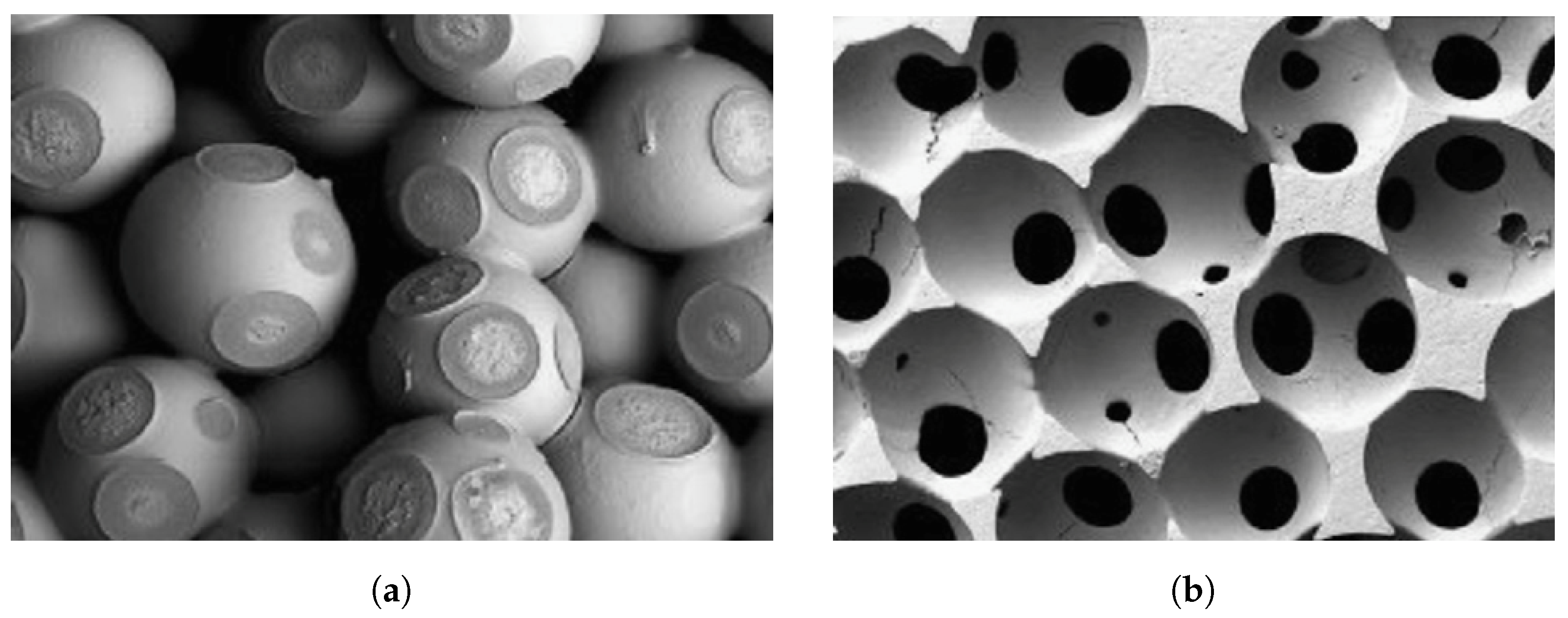
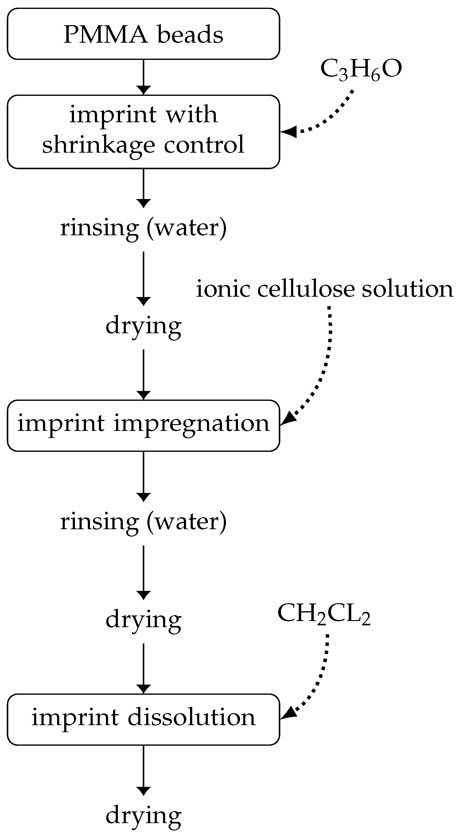
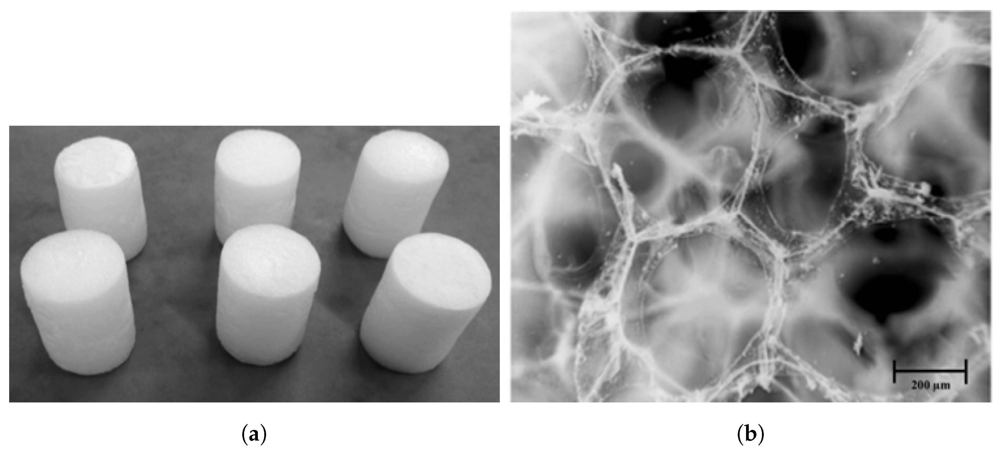
3.1. Basic Control of Organic Frame

The goal was to show how altering the PMMA frame affects the acoustic absorption of the resulting porous material. The properties of five tested samples are given in Table 2. The parameters that varied during manufacturing were the diameter D of the PMMA beads, which determines the diameter of the pores, and the shrinkage rate τ of the skeleton during the forming phase, which affects the theoretical diameter ϵ of the interconnections.
Among all the tests, we selected these five samples. They show the control this manufacturing process offers. They also had a homogeneous structure, as seen under the microscope. So, they are free from process-generated artifacts. These include partial pore crushing and localized tearing.
The normal incidence absorption curves (cf. Figure 5b) demonstrate how these changes impacted the sound performance of the foams. Reducing the pore size led to improved absorption. The best results were achieved with a sample featuring PMMA beads 200–400 µm in diameter, which showed an absorption peak of around 0.8 to 5 kHz. Notably, samples B and C, despite using the same range of ball diameters, exhibited a significant difference in performance. The ratio τ directly influenced the diameter of the interconnections, resulting in a more reticulated medium with larger diameters. This increased permeability to acoustic waves led to reduced absorption. As expected, the performance of the porous cellulose depended on its skeleton characteristics. The link between the shrinkage rate and the size of the PMMA beads used on the density of the material obtained is complex to establish. The structures from varying these two parameters can affect the PMMA’s impregnation by the cellulose. Using large-diameter beads creates gaps. Cellulose will fill them, increasing the density, as noted in the table. A more in-depth study, using tomography, could determine how much the shrinkage rate, along with the bead diameter, affects cellulose impregnation.
The acoustical properties, such as the static airflow resistivity σ , the tortuosity α , the viscous characteristic length Λ , and the thermal characteristic length Λ , are shown for the five cellulose sound absorbers in Table 3. The airflow resistivity partly characterizes the visco-inertial effects at low frequencies. This is when the viscous boundary layer is roughly the size of the pores. Tortuosity could be considered a measure of the disorder in the material. This value helps us understand the internal structure of the material. Λ controls the thermal effects at medium and high acoustical frequencies. It is related to the largest size of the pores. Λ controls the viscous effects at these frequencies and is related to the size of the connections between pores. These two parameters indirectly account for the assembly by partially dissolving PMMA beads. The porosity was determined as depicted in the previous section, while σ was measured directly using an airflow resistivity meter. The viscous and thermal characteristic lengths were obtained using an inverse method [33].
As shown in the table and the figure, the acoustic effectiveness of the porous cellulose is essentially due to its resistivity. For a porous material with oblique cylindrical pores, this value is linked to the radius of the pores by the following relation [34]:
σ = 8 η α ϕ R 2
where R is the radius of the pores. Our materials may not have the idealized structure; however, comparing the radius R from Equation (4) with the viscous and thermal characteristic lengths as functions of resistivity can be helpful. This comparison can suggest which parameters to adjust to optimize the acoustic performance of the porous cellulose. As the pore size decreases, the resistivity becomes more dependent on their radius ( Λ ). Conversely, when the pore size increases, the radius of the interconnections ( Λ ) becomes dominant. Tests on making porous ceramics have shown that the impression strength is limited for ϵ < r ¯ / 5 [28], implying that the radius of the interconnections must be slightly reduced for samples with a pore diameter over 400 µm. A pore diameter of less than 200 µm could enhance our material’s acoustic performance. However, using such small diameters for the cellulose solution requires optimizing the current process, which risks partial impregnation and collapse of the skeleton.

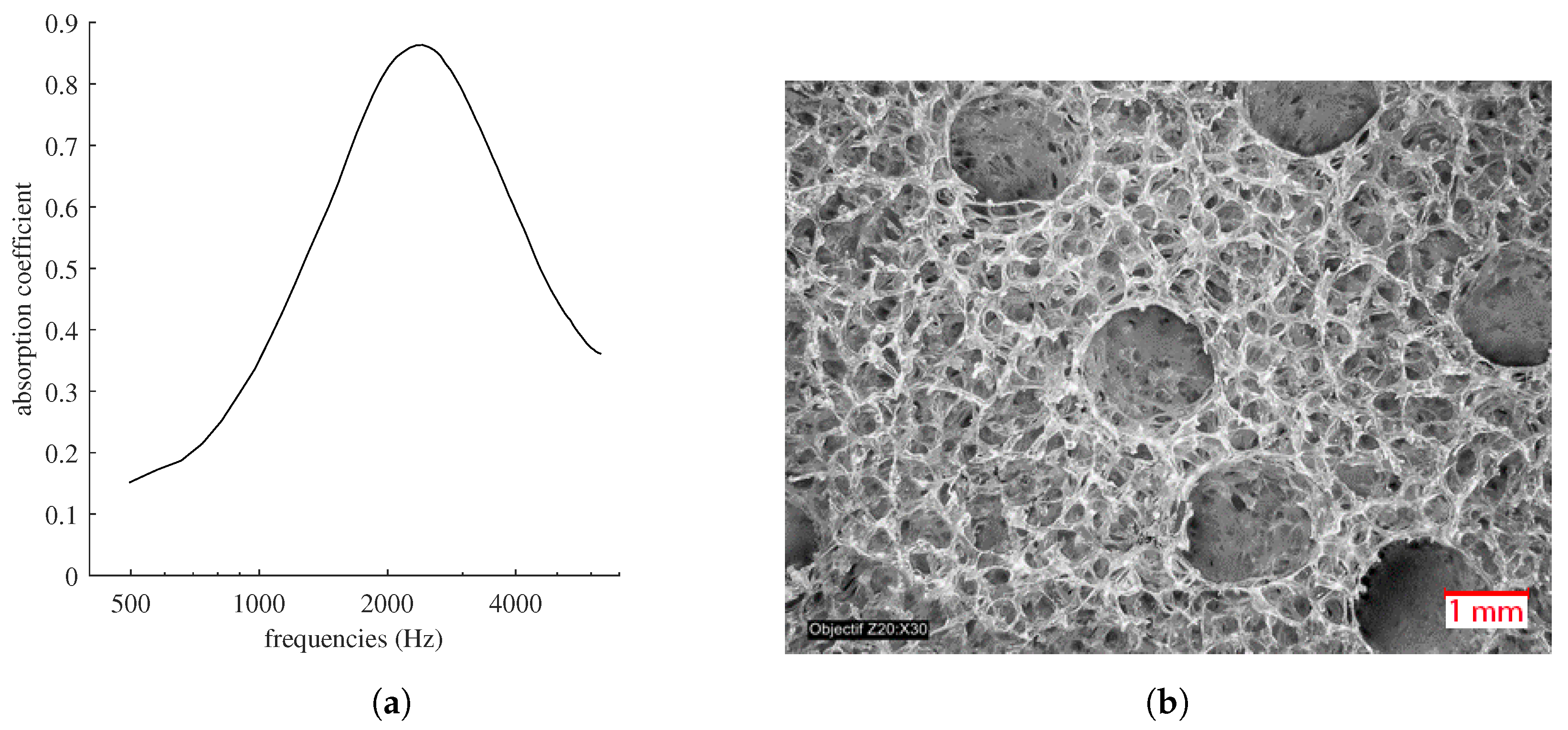
3.2. Double Porosity

The process for obtaining a material with double porosity is straightforward. PMMA rods or filaments are added to the beads. Figure 6a shows a test based on sample B from Table 2, with the difference that PMMA rods, each with a diameter of 1.75 mm, were arranged without concern for alignment or structuring the desired mesoporous network at the end (cf. Figure 6). We observed a radical change in performance toward low frequencies, a direct consequence of this double porosity [35]. However, with a ratio of only 4 between the pore sizes of the micro- and meso-networks, we are only halfway toward the admitted optimal ratio of 10. Using larger PMMA rods would allow for a closer approach to this aim, with less concern for the structural integrity of the foam compared to reducing the size of the beads. Also, this process opens the possibility of directly influencing the tortuosity of the mesoporous network by incorporating a more or less complex interweaving of PMMA filaments, thus overcoming the shape limits of double-porosity materials usually obtained by perforation [36].

3.3. Gradient-Porous Biomaterials

The manufacturing process showed that it is possible to control the size of the pores and their interconnections. It is also possible to manufacture gradients of porosity and interconnections. The implementation of property gradients occurs only in the first step of manufacturing the porous cellulose, namely the step of constructing the impression. This is why the manufacturing processes described below relate only to this step; the production of the skeleton and the dissolution of the impression remain identical to those described in the previous sections.

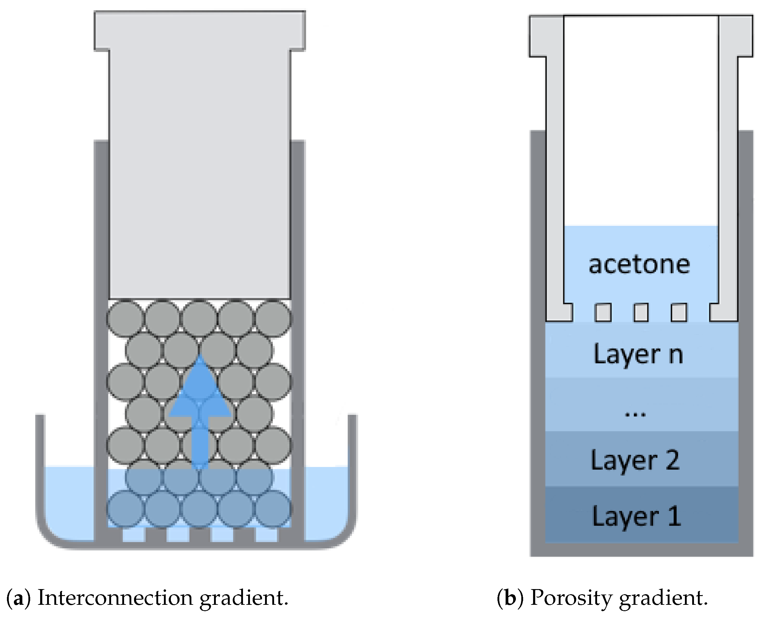
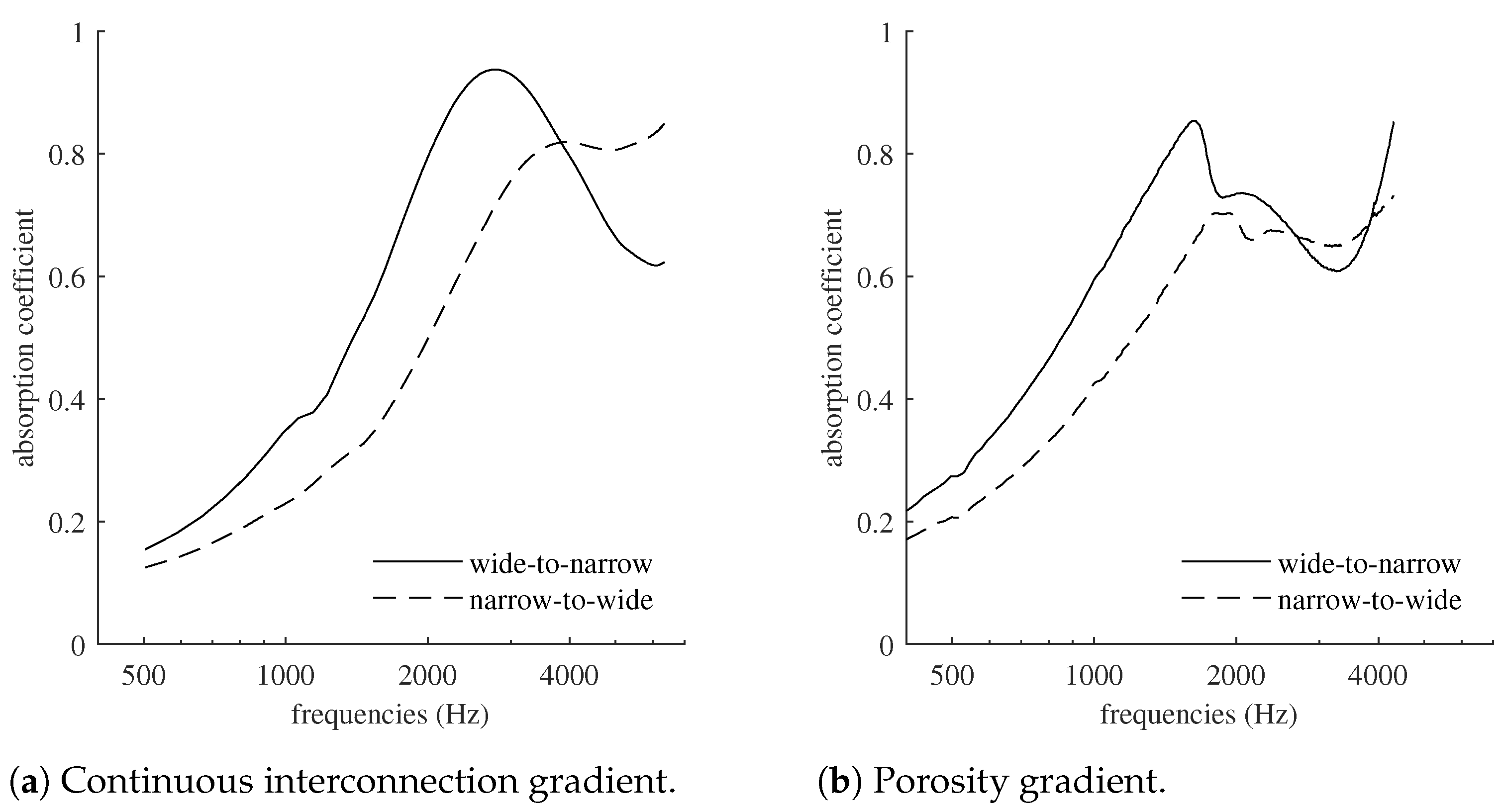
3.3.1. Continuous Interconnection Gradient

First, rather than producing a material with a discrete interconnection gradient, which would lead to impedance breaks between each layer with different granularity [37,38], we opted for a continuous gradient. To achieve a continuous gradient of interconnections, PMMA beads were placed in a mold with a perforated bottom (see Figure 7a). Similar to the basic process, the piston was used to compress the sacrificial material to achieve interpenetration between the beads. The mold was then placed in a crystallizer into which acetone was poured. The negative was impregnated until the acetone level reached its upper surface by capillarity. As the total immersion times between the bottom and the top differ, different interconnections were formed depending on the height. The interconnection gradient was confirmed by the difference in absorption between the two faces of the sample (cf. Figure 8a), with an imprint similar to the one used to obtain sample D from Table 2 (diameter of the beads ranging from 0.6 to 0.7 mm). The best performance was obtained for the wide-to-narrow case, where the face with the smallest interconnections was against the rigid termination of the impedance tube. A comparison with the results of sample D, which had the same bead diameter and similar thickness, showed an acoustic activity that was three times higher. This activity is defined as the area under the absorption curve normalized by the frequency range [39]. With the largest interconnections against the rigid termination, in the narrow-to-wide case (the sample being reversed), the gain in acoustic activity remained almost equal, although shifted toward higher frequencies. Note that this performance was obtained for a sample with a pore size ranging from 0.17 to 0.3 mm (cf. Figure 9), which, in the case of constant interconnections, is the one that presented the lowest absorption and the lowest resistivity.

3.3.2. Porosity Gradient

As in the ceramic manufacturing process, the porosity gradient was obtained by superimposing layers of PMMA beads of different diameters. To obtain the impression in a single step, a first layer of beads (smaller diameter) was placed in the mold, followed by a new layer of beads with a larger diameter, and so on until the last layer. Between each layer, the surface was flattened by placing a piston (see Figure 7b). A grid was placed on the last layer, and the perforated piston was inserted to keep the beads under pressure before immersion in acetone. The results shown in Figure 8b were obtained with four layers of beads (diameters of each layer: 0.4 to 0.5, 0.5 to 0.6, 0.6 to 0.7, and 0.7 to 0.8 mm), each with identical thickness, resulting in a 4.2 cm foam once completely manufactured and dried. Here again, the absorption curves reflect the creation of an orthotropic material: depending on the face in contact with the incident wave, the response of the foam changes significantly. Figure 10 illustrates the effect of this manufacturing process on the pore size, with an observed ratio that can approach 2 between the two opposite sides of the porosity gradient material.

4. Conclusions

Inspired by a ceramics-making method, the porous materials discussed in this article highlight the benefits of a complex yet promising manufacturing process. By controlling the pore size, interconnections, and spatial distribution, this process enables the creation of materials with remarkable properties. However, producing porous cellulose requires multiple steps, each requiring special care to prevent damage to the material’s internal structure and its acoustic performance. Another consideration is whether this process can produce larger materials, similar to those commonly used. Three-dimensional printing is well suited for this change in scale. Indeed, the skeleton can be directly created using PMMA filament, bypassing the time-consuming and difficult-to-control process of forming it through chemical dissolution. The gaps and inconsistencies often observed when employing the FDM printing technique can be utilized to create a microporous network in addition to the printed macroporous one, resulting in a material with double porosity. Nevertheless, the proposed fabrication process allows for the production of hybrid materials. For example, incorporating a solid body into the frame of PMMA beads or adding fine particles or fibers is fairly straightforward and does not require significant changes to the manufacturing method.

Author Contributions

Conceptualization, J.L., B.G. and A.L.; Formal analysis, J.L.; Investigation, J.L.; Methodology, J.L. and B.G.; Supervision, A.L.; Writing—original draft, A.L.; Writing—review and editing, B.G. All authors have read and agreed to the published version of the manuscript.

Funding

This research received no external funding.

Data Availability Statement

The original contributions presented in the study are included in the article, further inquiries can be directed to the corresponding author.

Conflicts of Interest

The authors declare no conflict of interest.

References

  1. Al-Qararah, A.M.; Ekman, A.; Hjelt, T.; Ketoja, J.A.; Kiiskinen, H.; Koponen, A.; Timonen, J. A unique microstructure of the fiber networks deposited from foam–fiber suspensions. Colloids Surfaces Physicochem. Eng. Asp. 2015, 482, 544–553. [Google Scholar] [CrossRef]
  2. Ferreira, F.V.; Otoni, C.G.; Kevin, J.; Barud, H.S.; Lona, L.M.; Cranston, E.D.; Rojas, O.J. Porous nanocellulose gels and foams: Breakthrough status in the development of scaffolds for tissue engineering. Mater. Today 2020, 37, 126–141. [Google Scholar] [CrossRef]
  3. Zieliński, T.G.; Dauchez, N.; Boutin, T.; Leturia, M.; Wilkinson, A.; Chevillotte, F.; Bécot, F.X.; Venegas, R. Taking advantage of a 3D printing imperfection in the development of sound-absorbing materials. Appl. Acoust. 2022, 197, 108941. [Google Scholar] [CrossRef]
  4. Xue, Y.; Nobles, L.P.; Sharma, B.; Bolton, J.S. Designing hybrid aerogel-3D printed absorbers for simultaneous low frequency and broadband noise control. Mater. Des. 2024, 242, 113026. [Google Scholar] [CrossRef]
  5. Arjunan, A.; Baroutaji, A.; Robinson, J.; Vance, A.; Arafat, A. Acoustic metamaterials for sound absorption and insulation in buildings. Build. Environ. 2024, 251, 111250. [Google Scholar] [CrossRef]
  6. Godbold, O.; Soar, R.; Buswell, R. Implications of solid freeform fabrication on acoustic absorbers. Rapid Prototyp. J. 2007, 13, 298–303. [Google Scholar] [CrossRef]
  7. Setaki, F.; Tian, F.; Turrin, M.; Tenpierik, M.; Nijs, L.; Van Timmeren, A. 3D-printed sound absorbers: Compact and customisable at broadband frequencies. Archit. Struct. Constr. 2023, 3, 205–215. [Google Scholar] [CrossRef]
  8. Cardone, L.; De Rosa, S.; Petrone, G.; Catapane, G.; Squillace, A.; Landolfi, L.; Detry, A. Acoustic characteristics evaluation of an innovative metamaterial obtained through 3D printing technique. In Proceedings of the Aeronautics and Astronautics: AIDAA XXVII International Congress, Padova, Italia, 4–7 December 2023; Materials Research Forum LLC: Millersville PA, USA, 2023; Volume 37, p. 325. [Google Scholar]
  9. Cingolani, M.; Fratoni, G.; Barbaresi, L.; D’orazio, D.; Hamilton, B.; Garai, M. A trial acoustic improvement in a lecture Hall with MPP sound absorbers and FDTD acoustic simulations. Appl. Sci. 2021, 11, 2445. [Google Scholar] [CrossRef]
  10. Fusaro, G.; Barbaresi, L.; Cingolani, M.; Garai, M.; Ida, E.; Prato, A.; Schiavi, A. Investigation of the impact of additive manufacturing techniques on the acoustic performance of a coiled-up resonator. J. Acoust. Soc. Am. 2023, 153, 2921. [Google Scholar] [CrossRef]
  11. Li, X.; Chua, J.W.; Yu, X.; Li, Z.; Zhao, M.; Wang, Z.; Zhai, W. 3D-Printed Lattice Structures for Sound Absorption: Current Progress, Mechanisms and Models, Structural-Property Relationships, and Future Outlook. Adv. Sci. 2024, 11, 2305232. [Google Scholar] [CrossRef]
  12. Jagadeesh, P.; Puttegowda, M.; Rangappa, S.M.; Alexey, K.; Gorbatyuk, S.; Khan, A.; Doddamani, M.; Siengchin, S. A comprehensive review on 3D printing advancements in polymer composites: Technologies, materials, and applications. Int. J. Adv. Manuf. Technol. 2022, 121, 127–169. [Google Scholar] [CrossRef]
  13. Li, Y.; Ren, X.; Zhu, L.; Li, C. Biomass 3D printing: Principles, materials, post-processing and applications. Polymers 2023, 15, 2692. [Google Scholar] [CrossRef] [PubMed]
  14. Zheng, Z.; Li, Y.; Yang, W. Absorption properties of natural fiber-reinforced sandwich structures based on the fabric structures. J. Reinf. Plast. Compos. 2013, 32, 1561–1568. [Google Scholar] [CrossRef]
  15. Tiuc, A.E.; Vermeşan, H.; Gabor, T.; Vasile, O. Improved sound absorption properties of polyurethane foam mixed with textile waste. Energy Procedia 2016, 85, 559–565. [Google Scholar] [CrossRef]
  16. Zhu, X.; Kim, B.J.; Wang, Q.; Wu, Q. Recent Advances in the Sound Insulation Properties of Bio-based Materials. BioResources 2014, 9, 1764–1786. [Google Scholar] [CrossRef]
  17. Oldham, D.J.; Egan, C.A.; Cookson, R.D. Sustainable acoustic absorbers from the biomass. Appl. Acoust. 2011, 72, 350–363. [Google Scholar] [CrossRef]
  18. Del Rey, R.; Alba, J.; Arenas, J.P.; Sanchis, V.J. An empirical modelling of porous sound absorbing materials made of recycled foam. Appl. Acoust. 2012, 73, 604–609. [Google Scholar]
  19. Trematerra, A.; Lombardi, I. Acoustic Properties of Cellulose. In Proceedings of the IOP Conference Series: Materials Science and Engineering, Hyderabad, India, 13–14 July 2017; IOP Publishing: Bristol, UK, 2017; Volume 225, p. 012082. [Google Scholar]
  20. Arenas, J.P.; Rebolledo, J.; Rey Tormos, R.M.d.; Alba Fernández, J. Sound absorption properties of unbleached cellulose loose-fill insulation material. BioResources 2014, 9, 6227–6240. [Google Scholar] [CrossRef]
  21. Seciureanu, M.; Nastac, S.M.; Guiman, M.V.; Nechita, P. Cellulose Fibers-Based Porous Lightweight Foams for Noise Insulation. Polymers 2023, 15, 3796. [Google Scholar] [CrossRef]
  22. Nastac, S.M.; Nechita, P.; Guiman, M.V.; Roman, M.; Rosca, I.C. Applications of Xylan Derivatives to Improve the Functional Properties of Cellulose Foams for Noise Insulation. Polymers 2023, 15, 4648. [Google Scholar] [CrossRef]
  23. Muchlisinalahuddin, M.; Dahlan, H.; Mahardika, M.; Rusli, M. Cellulose-based Material for Sound Absorption and Its Application—A Short Review. In Proceedings of the BIO Web of Conferences, Bogor, Indonesia, 21–22 September 2023; EDP Sciences: Les Ulis, France, 2023; Volume 77, p. 01003. [Google Scholar]
  24. Miranda-Valdez, I.Y.; Coffeng, S.; Zhou, Y.; Viitanen, L.; Hu, X.; Jannuzzi, L.; Puisto, A.; Kostiainen, M.A.; Mäkinen, T.; Koivisto, J.; et al. Foam-formed biocomposites based on cellulose products and lignin. Cellulose 2023, 30, 2253–2266. [Google Scholar] [CrossRef]
  25. Taiwo, E.M.; Yahya, K.; Haron, Z. Potential of using natural fiber for building acoustic absorber: A review. In Proceedings of the Journal of Physics: Conference Series, Selangor, Malaysia, 7 March 2019; IOP Publishing: Bristol, UK, 2019; Volume 1262, p. 012017. [Google Scholar]
  26. Mahasaranon, S.; Horoshenkov, K.V.; Khan, A.; Benkreira, H. The effect of continuous pore stratification on the acoustic absorption in open cell foams. J. Appl. Phys. 2012, 111, 084901. [Google Scholar] [CrossRef]
  27. Geslain, A.; Groby, J.P.; Dazel, O.; Mahasaranon, S.; Horoshenkov, K.; Khan, A. An application of the Peano series expansion to predict sound propagation in materials with continuous pore stratification. J. Acoust. Soc. Am. 2012, 132, 208–215. [Google Scholar] [CrossRef] [PubMed]
  28. Descamps, M.; Duhoo, T.; Monchau, F.; Lu, J.; Hardouin, P.; Hornez, J.; Leriche, A. Manufacture of macroporous β-tricalcium phosphate bioceramics. J. Eur. Ceram. Soc. 2008, 28, 149–157. [Google Scholar] [CrossRef]
  29. Joly, N.; Granet, R.; Krausz, P. Crosslinking of cellulose by olefin metathesis. J. Carbohydr. Chem. 2003, 22, 47–55. [Google Scholar] [CrossRef]
  30. Panneton, R.; Gros, E. A missing mass method to measure the open porosity of porous solids. Acta Acust. United Acust. 2005, 91, 342–348. [Google Scholar]
  31. ISO 10534-2; Acoustics—Determination of Sound Absorption Coefficient and Impedance in Impedance Tubes. International Organization for Standardization: Geneva, Switzerland, 2001.
  32. Sambucci, M.; Sibai, A.; Fattore, L.; Martufi, R.; Lucibello, S.; Valente, M. Finite element multi-physics analysis and experimental testing for hollow brick solutions with lightweight and eco-sustainable cement mix. J. Compos. Sci. 2022, 6, 107. [Google Scholar] [CrossRef]
  33. Atalla, Y.; Panneton, R. Inverse acoustical characterization of open cell porous media using impedance tube measurements. Can. Acoust. 2005, 33, 11–24. [Google Scholar]
  34. Allard, J.; Allard, J. Sound propagation in cylindrical tubes and porous materials having cylindrical pores. In Propagation of Sound in Porous Media: Modelling Sound Absorbing Materials; John Wiley & Sons: Hoboken, NJ, USA, 1993; pp. 48–78. [Google Scholar]
  35. Sgard, F.C.; Olny, X.; Atalla, N.; Castel, F. On the use of perforations to improve the sound absorption of porous materials. Appl. Acoust. 2005, 66, 625–651. [Google Scholar] [CrossRef]
  36. Liu, X.; Ma, X.; Yu, C.; Xin, F. Sound absorption of porous materials perforated with holes having gradually varying radii. Aerosp. Sci. Technol. 2022, 120, 107229. [Google Scholar] [CrossRef]
  37. Doutres, O.; Atalla, N. Sound absorption properties of functionally graded polyurethane foam. In Proceedings of the INTER-NOISE and NOISE-CON Congress and Conference Proceedings, New York, NY, USA, 19–22 August 2012; Institute of Noise Control Engineering: Wakefield, MA, USA, 2012; Volume 2012, pp. 679–688. [Google Scholar]
  38. Sacristan, C.; Dupont, T.; Sicot, O.; Leclaire, P.; Verdière, K.; Panneton, R.; Gong, X.L. A mixture approach to the acoustic properties of a macroscopically inhomogeneous porous aluminum in the equivalent fluid approximation. J. Acoust. Soc. Am. 2016, 140, 2847–2855. [Google Scholar] [CrossRef]
  39. Verdejo, R.; Stämpfli, R.; Alvarez-Lainez, M.; Mourad, S.; Rodriguez-Perez, M.; Brühwiler, P.; Shaffer, M. Enhanced acoustic damping in flexible polyurethane foams filled with carbon nanotubes. Compos. Sci. Technol. 2009, 69, 1564–1569. [Google Scholar] [CrossRef]
Figure 1. (a) shrunk PMMA beads and (b) resulting porous ceramic [28].
Acoustics 06 00059 g001
Figure 2. Construction of the frame with PMMA beads.
Acoustics 06 00059 g002
Figure 3. Synopsis of the manufacturing process.
Acoustics 06 00059 g003
Figure 4. (a) The 6 samples characterized in Table 1 and (b) a microscopic view of one sample.
Acoustics 06 00059 g004
Figure 5. (a) Max/min and mean absorption coefficients of the 6 samples depicted in Table 1 and (b) the 5 samples depicted in Table 2.
Acoustics 06 00059 g005
Figure 6. (a) Absorption coefficient. (b) Microscopic view of porous cellulose with double porosity.
Acoustics 06 00059 g006
Figure 7. First manufacturing step of gradient foams.
Acoustics 06 00059 g007
Figure 8. Absorption coefficients of gradient-porous biomaterials.
Acoustics 06 00059 g008
Figure 9. Pore-size estimation for the continuous interconnection gradient material acoustically characterized in Figure 8a.
Acoustics 06 00059 g009
Figure 10. Pore-size estimation for the porosity gradient material acoustically characterized in Figure 8b.
Acoustics 06 00059 g010
Table 1. Properties of the samples at the end of the manufacturing process.
Samplem (g)h (mm)d (mm) V t ( cm 3 ) V c ( cm 3 ) ϕ (%) ρ (kg/m3)
10.549235.5728.0922.040.380.98324.9
20.572035.2528.1321.910.390.98226.1
30.589434.8627.6520.930.410.98128.2
40.461235.1225.7918.350.320.98325.1
50.547934.8327.6220.870.380.98226.2
60.579235.7827.5721.360.400.98127.1
Table 2. Properties of samples depicted in Figure 5b.
SampleD (mm)m (g)h (mm)d (mm) τ (%) ρ (kg/m3)
A0.2–0.40.1718.122.04924.6
B0.5–0.60.2220.321.91528.7
C0.5–0.60.2119.120.931131.9
D0.6–0.70.2320.918.35541.6
E0.7–0.80.2119.120.875.932.1
Table 3. Acoustical properties of samples listed in Table 2 and illustrated in Figure 5b.
Sample σ ( N . s . m 4 ) α Λ (µm) Λ (µm) ϕ
A51921.051141920.990
B20451.002733130.989
C11941.073404560.989
D6851.024687100.989
E7501.124495900.989
Disclaimer/Publisher’s Note: The statements, opinions and data contained in all publications are solely those of the individual author(s) and contributor(s) and not of MDPI and/or the editor(s). MDPI and/or the editor(s) disclaim responsibility for any injury to people or property resulting from any ideas, methods, instructions or products referred to in the content.

