Abstract
This work presents a numerical study on atmospheric sound propagation over rough water surfaces with the aim of improving predictions of sound propagation over long distances. A method for generating pseudorandom sea profiles consistent with sea wave spectra is presented. The proposed method is suited for capturing the logarithmic nature of the energy distribution of the waves. Sea profiles representing fully developed seas for sea states 2, 3, 4, and 5 are generated from the Elfouhaily et al. (ECKV) sea wave spectra. Excess attenuation caused by refraction and surface roughness is predicted with a parabolic equation (PE) solver. A novel method for estimating equivalent effective impedance based on PE predictions at different sea states is presented. Parametric expressions using acoustic frequency and significant wave height are developed for effective surface impedances. In this work, sea surface roughness is on a scale comparable with the acoustic wavelength. Under this condition, the acoustic scattering is primarily incoherent. This work shows the limitations of using an equivalent surface impedance in such incoherent scattering cases.
1. Introduction
For many decades, atmospheric sound propagation studies have been conducted predominantly on land [,,,], with only a few studies conducted over sea and small bodies of water []. In recent years, research on sound propagation in coastal areas has garnered increased interest, driven by the growth of off-shore wind farms [,,], oil and gas platforms, offshore airport construction [], and other activities. However, the study of sound propagation over the sea is also critical for the detection of vessels at sea in cases of low visibility at ranges on the order of kilometers. Accurate predictions of sound pressure level for noise sources far from the shore require an accurate representation of the acoustic contribution of the rough surface of the water. While the literature supporting a methodology to account for attenuation due to ground surfaces is robust [], that is not the case for attenuation over long spans of water. This work aims to improve the accuracy of sound attenuation introduced by the water roughness.
Atmospheric sound propagation over water is strictly coupled with meteorological conditions, which are responsible for acoustic refraction [,]. Another important influence is the geometry of the water surface, which is responsible for acoustic scattering when acoustic wavelengths are comparable with the characteristic size of the water roughness. Parabolic equation (PE) methods, such as the CNPE (Crank–Nicolson PE) [] and the GFPE (Green’s Function PE) [], have been commonly used to model acoustic refraction. However, those methods are applicable to ranges with smooth variations of the ground level and, thus, are not directly able to account for arbitrary geometries. The Beilis–Tappert PE method [] can efficiently model atmospheric sound propagation over irregular terrain in cases with local slopes of less than 20° []. However, this work considers higher sea states with slopes exceeding 20°. To account for local slopes beyond 20° but not exceeding 30°, the CNPE model can be modified to obtain the GTPE (General Terrain PE) []. The GTPE modification, however, comes with a significant computational cost. The GTPE method can be used to quantify the effect of surface acoustic scattering during atmospheric sound propagation. In the case of propagation over the ocean, the roughness can be considered by generating pseudorandom surfaces consistent with the sea state. The combination of the GTPE with random surface roughness has been applied to underwater acoustics [], but the application to the atmospheric problem has not been reported. The large computational cost of this method makes it unsuitable for real-time high-frequency (above 1 kHz), long-range (on the order of kilometers) atmospheric sound propagation. To reduce the computational cost, a flat surface with an equivalent impedance can be used [,]. The validation of this approach applied to water roughness is lacking in the literature.
In this paper, a numerical method is proposed to estimate equivalent surface impedances for water roughness representing sea states from 2 to 5. One previous approach [] found an equivalent surface impedance using the Delany and Bazley [] model. The impedance was used to inform PE predictions compared with long-range acoustic measurements. A second approach by Van Renterghem et al. [] used Finite Difference Time Domain (FDTD) simulations over short distances (source and receiver separated by 5 m) to replicate a method previously reported by Boulanger and Attenborough [] to find equivalent impedances of pseudorandom sea surfaces. The equivalent impedance determined with the FDTD method was implemented in PE predictions of atmospheric acoustic propagation above water over a 10 km range. The method proposed in this work differs from that of Van Renterghem et al. in that this work uses GTPE simulations over a 1 km range to estimate the equivalent impedance of different sea states. This longer simulation range overcomes the inability to capture the acoustic contribution of sea waves with wavelengths larger than 5 m. Additional contributions of this work are (1) eliminating the use of a nonphysical model (Delany and Bazley) to estimate surface impedances, (2) an alternative approach to generating pseudorandom sea surfaces, and (3) an approach to relating the surface impedance of different sea states to the significant wave height.
The paper is organized as follows: Section 2.1 details the approach used to model sea surfaces. Section 2.2 reviews the Monin–Obukhov similarity theory and discusses the meteorological data used in this work to inform a PE solver. Section 2.3 describes how acoustic excess attenuation is predicted over a rough sea using a GTPE solver. Section 2.4 reviews the methods used to estimate equivalent impedances for rough seas and presents this work’s approach. Section 3 and Section 5 present the results and conclusions of this work.
2. Materials and Methods
2.1. Modeling Sea Surfaces
Existing models that relate wave height to wind speed have been studied for open waters, like seas and oceans [,,]. In this paper, such models are used to predict water roughness. The assumptions made throughout this paper are (1) the sea is fully developed, (2) predominant wind waves are aligned with the mean wind direction, and (3) water depth effects are negligible.
2.1.1. Background on Sea Spectra
PM Spectrum
In the absence of breaking waves, the sea surface can be described by a sea spectrum, a frequency distribution of energy. The most popular sea spectrum for fully developed seas is the Pierson and Moskowitz (PM) spectrum [], , defined in the following Equation (1):
where k is the angular spatial frequency; ; ; g is the acceleration of gravity, in m/s2; and is the wind speed in m/s measured at a 19 m height. The spectrum depends only on , which can often be replaced by wind speed measured at a 10 m height with an approximation of . This model has been applied to sound scattering predictions due to water roughness in both atmospheric and underwater problems [,,]. Despite the broad use and a recent revisitation by Alves et al., the PM spectrum is unsuitable for describing high-frequency gravity waves or capillary waves []. Water roughness in the high-frequency range can have a non-negligible influence on atmospheric sound propagation.
ECKV Spectrum
A model that is better suited for describing high-frequency sea waves is given by the Elfouhaily, Chapron, Katsaros, and Vandemark (ECKV) [] sea spectrum. It is also important to note that, for a fully developed sea, the ECKV spectrum, like the PM spectrum, is only a function of wind speed. The ECKV spectrum, , accounts for two frequency regimes, as shown in the following Equation (2):
where is the low-frequency portion of the spectrum that considers the gravity waves, and is the high-frequency portion of the spectrum that considers capillary waves. These two portions of the spectrum are similarly modeled as follows:
In Equation (3), depends on the generalized Phillips–Kitaigorodskii equilibrium range parameter for long waves [], , which in turn depends on the dimensionless wave-age parameter, , such that . In the case of a fully developed sea, . The wave phase speed, , is given by . The wavenumber, , which corresponds to the gravity–capillary peak, is a constant 370 rad/m. The phase speed of the dominant long waves, , can be found as , where is the wavenumber of the spectral peak. The long-wave side-effect function, , is defined as follows:
where is the Pierson–Moskowitz shape function and is the Joint North Sea Wave Project (JONSWAP) [] shape function. These functions are defined as follows:
where is for a fully developed sea and is given by the following Equation (7):
In Equation (4), depends on the generalized Phillips–Kitaigorodskii equilibrium range parameter for short waves, , given in the following Equation (8):
where is the minimum short-wave phase speed associated with the gravity–capillary peak, and it is given by = 0.23 m/s. Friction velocity, , is given by the following Equation (9):
where the wind speed at the ground level, , is usually negligible. As this work is concerned with sound propagation over water, the drag coefficient, , is therefore representative of wave–wind interactions. For wind speed, , greater than 1 m/s, the following Equation (10) has been widely used to estimate the drag coefficient over water []:
Spectra Comparison
Differences between the PM spectrum and the ECKV spectrum for fully developed seas are presented in Figure 1. The largest discrepancies between the spectra can be observed at sea spatial frequencies larger than approximately 10 rad/m. The ECKV model excludes the shortest sea wave wavelengths compared with the PM. Acoustic scattering becomes relevant when the acoustic wavelength is comparable with the physical wavelength of the sea surface. For a sea spatial frequency of 10 rad/m, the wavelength of the sea matches the wavelength of sound in air at 550 Hz. This study considers acoustic frequencies in the range 125–2000 Hz. The ECKV spectrum is therefore chosen, as it was developed to model high-frequency sea waves, with wavelengths comparable with that of atmospheric sound in the frequency range considered in this work.
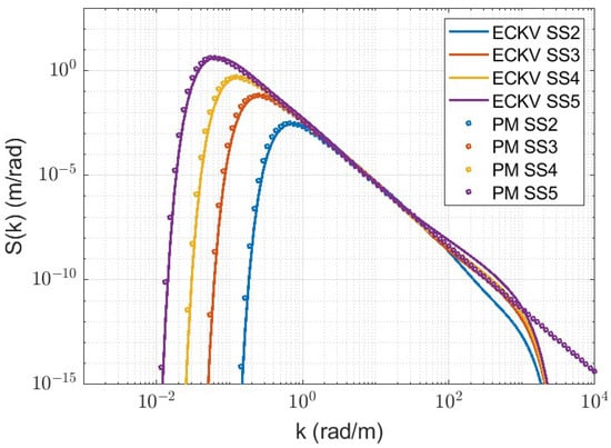
Figure 1.
Comparison between PM and ECKV spectra for fully developed seas. Spectra for sea states 2, 3, 4, and 5 are obtained with = 3, 5, 7 and 10 m/s, respectively. The largest discrepancies between the spectra at a given sea state can be observed at spatial frequencies larger than approximately 10 rad/m.
2.1.2. Generating Pseudorandom Sea Surfaces
Pseudorandom sea surfaces can be generated using the inverse spatial Fourier transform (FFT) of power sea spectra as described in previous works [,]. This approach requires a uniform distribution of spatial frequency, k. The resolution, , and the minimum spatial frequency, , of this distribution are both equal to , where L is the horizontal length of the generated surfaces. As a consequence, the spectra are always unevenly sampled, because of the logarithmic nature of the wave energy distribution. In other words, using a uniform distribution of k leads to an undersampling of the low-frequency side of the spectrum, which contains the majority of the energy.
In this work, an alternative approach to generate pseudorandom sea surfaces is proposed, similar to that of Kay et al. []. The method consists of replacing the wave height, , with a discrete sum of N sinusoids, as shown in the following Equation (12):
where the symbol ℜ stands for real part. The sinusoid amplitudes, , are given by the spectral density contained in a finite frequency interval. The argument depends on a spatial coordinate r. In Equation (12), is the average value of a wave spectrum over the frequency band centered at with the width . The amplitudes are multiplied by , a random number drawn from a normal distribution. This distribution has a unit mean and standard deviation of 0.2. The standard deviation of 0.2 satisfies the condition that the maximum wave height, , is approximately 1.9 times the significant wave height, , over 1000 waves []. Finally, the phase factor is obtained from , a random number drawn from a uniform distribution with the range [0 1].
The method presented in this work does not require the resolution to depend on the spatial coordinate r. Therefore, it allows the generation of pseudorandom sea surfaces for any range L without affecting the spatial frequency resolution. With this method, both linear and non-linear discretizations of k can be used. However, a logarithmic discretization of k is particularly advantageous as it better captures the logarithmic nature of the energy distribution of the waves. An alternative discretization is the equal area method, where is held constant. A disadvantage of the equal area method occurs at the tail of the distribution, where a single sinusoid represents a wider frequency band, leading to a possible under-representation of capillary waves.
For each sea state, ten wave profiles of a 1 km range are generated. Using more than ten wave profiles will reduce the incoherent variation of the acoustic results, leading to a mean SPL difference far less than a decibel. That difference is considered acceptable in this work due to the computational cost of increasing the number of simulations. The waves are generated using Equation (12), where is the ECKV spectrum for a fully developed sea and the spatial frequency k is logarithmically discretized over 1000 bands in the range [0.01 400] rad/m. The upper limit of this range was chosen to be larger than the spatial frequency of a 20 kHz sound in air. The spatial resolution of the sea profile, , is acoustic frequency dependent, and it is set to be one-tenth of the acoustic wavelength. Examples of four sea profiles corresponding to sea states from 2 to 5 are shown in the following Figure 2:
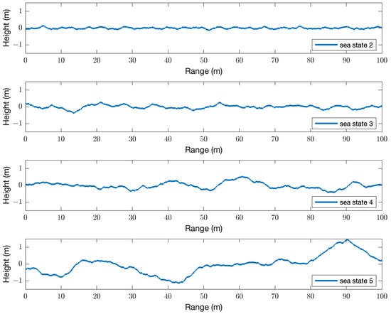
Figure 2.
Sea profiles generated from the ECKV spectrum for sea states from 2 to 5. Note that x- and y-axis are not on the same scale.
The mean sea surface elevation is at m. The significant wave heights, , of each profile can be measured as , where is the standard deviation of the water surface elevation []. The average significant wave heights obtained for = 3, 5, 7, and 10 m/s found over the ten realizations are 0.17, 0.47, 0.88, and 1.8 m, respectively. These sets of sea profiles are referred to as sea states 2, 3, 4, and 5, respectively []. Sea state 1 has not been included in this study because acoustic scattering in the frequency range considered is minimal. The slopes of the generated surfaces do not exceed 30°, and as such, the surfaces are suited for use in a GTPE solver.
To validate the generated profiles, a spectrum can be estimated and compared with the ECKV spectrum. An example of this comparison is shown in Figure 3. It demonstrates good agreement between the generated profiles’ spectra and the ECKV spectrum.

Figure 3.
Comparison between the ECKV spectrum and the averaged spectrum of the generated pseudorandom sea surface profiles, , for = 7 m/s. The spectra of the pseudorandom sea surface profiles are averaged over 10 (left), 100 (center), and 1000 (right) realizations.
2.2. Modeling Refraction
2.2.1. Monin–Obukhov Similarity Theory
When estimating sound propagation in the atmosphere, refraction effects must be properly modeled. The Monin–Obukhov similarity theory (MOST) [] has been widely used to accurately model wind and temperature profiles in the atmospheric surface layer [], and has commonly been applied to estimate sound propagation in the atmosphere [,,,]. MOST has long been applied to model the marine atmospheric boundary layer (MABL) []. According to this theory, wind, temperature, and humidity profiles can be obtained from normalized variables: , , and . The wind speed scale is given by the friction velocity, . The temperature and specific humidity scales, and , are defined as follows:
where and are the sensible and latent heat fluxes, is the density of air, is the specific heat at a constant pressure of air, and is the latent heat of vaporization for water. The vertical temperature profile, , can be obtained from MOST, as shown in Equation (14):
where z is the elevation and is the reference elevation, = 0.0098 K/m is the adiabatic lapse rate, = 0.95 is the turbulent Prandtl number in neutral stratification, = 0.4 is the Von Kármán constant, is the integral of the universal profile function [] defined in Equations (20) and (21), and is the Obukhov length, given by the following Equation (15):
where is the air temperature at the surface.
Within the atmospheric boundary layer, the proportion of turbulence produced by buoyancy as compared with that produced by wind shear is an indicator of the stability of the atmosphere. This proportion can be expressed as the ratio . For a neutral atmosphere, the effect of buoyancy on density stratification is negligible. In this case, the sensible heat flux tends toward zero as the heat exchange between ground and air is negligible. Thus, will tend toward infinity. Cases in which buoyancy is the driving force can result in either a stable or unstable atmosphere. In either case, cannot be zero and the magnitude of is therefore small. It also follows that shear effects are relevant only close to the surface. In unstable conditions, the heat flux from the ground is positive: air parcels tend to rise due to heating from the ground. In stable conditions, it is the opposite: is negative and air tends to sink. When the stratification is very stable, MOST does not apply. The constant flux assumption is not met as the turbulent mixing is missing. Archer et al. [] suggests values of 5 m 100 m for very stable conditions in the MABL. For heights such that , turbulence is mostly suppressed. The Obukhov length can then also be interpreted as the elevation limit for the applicability of MOST [].
The vertical wind speed profile, , can be modeled as follows:
where is the integral of the universal profile function, defined in Equation (20) and in Equation (21), and is the roughness length. Equation (16) is valid only for heights . The gradient of wind near the surface is primarily driven by the roughness length. Over water, depends on friction velocity according to the following Equation (17), the Charnock equation []:
where is the Charnock parameter. This relationship accounts for an increase in roughness as wave heights grow due to increasing surface stress. Different estimations of can be found in the literature, with smaller values for open sea and slightly larger values for coastal regions []. In this work, is set equal to 0.0144, as suggested by Garratt [].
According to MOST, humidity follows the same profile function as temperature. The specific humidity profile, , is then defined in the following Equation (18):
Specific humidity is related to the concentration of water vapor, C, as . However, since in the atmosphere , with typical values of 0.02 in tropical marine atmospheres, the approximation is often used [].
The effective sound speed profile is therefore modeled as [] follows:
where is the ratio of specific heats for dry air and is the air gas constant. From Equation (19), it can be noted that the effect of on the sound speed profile is significantly smaller than that of temperature; however, in this work, it will not be neglected.
The universal profile functions in this manuscript follow the notation given by Van Renterghem et al. []. For a stable atmosphere [], ():
where
For an unstable atmosphere [], ():
2.2.2. Meteorological Data
To best depict realistic refraction scenarios, parameters needed to estimate sound speed profiles are obtained from the SEAFLUX [] database. SEAFLUX is a satellite-based dataset of surface turbulent fluxes over the global oceans with 1 h time resolution and spatial resolution on the order of kilometer.
Meteorological data from SEAFLUX has been selected by season and time of day. Data have been grouped according to wind speed, with bins centered at 3, 5, 7, and 10 m/s, with a tolerance of ±0.25 m/s. Those bins correspond to sea states 2, 3, 4, and 5. The SEAFLUX parameters corresponding to selected bins are used to then obtain , , and , as shown in Section 2.2.1. Equation (19) yields a profile for each case. A ray tracer has been used over a 1 km range to determine the highest acoustic path deflected back at the surface by downward refraction, . Instances outside the limit of validity of MOST such that are discarded. For each bin, the average seasonal diurnal and nocturnal wind, temperature, and specific humidity profiles are obtained from the occurrences that meet all of the criteria. These profiles are then averaged by season and time of day. An example of summer, nocturnal profiles is shown in Figure 4, along with the corresponding profile.
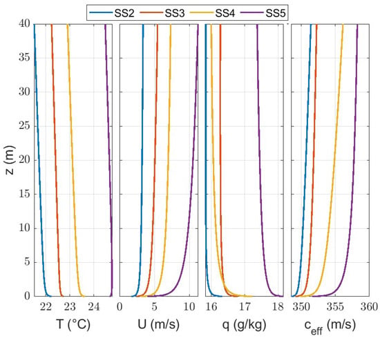
Figure 4.
Average temperature, ; wind speed, ; and specific humidity, , profiles, along with their respective effective sound speed profile, . Profiles are obtained as the average of nightly summer instances of wind speed corresponding to sea states from 2 to 5.
A location offshore from Duck, NC, has been selected to extract meteorological data from SEAFLUX. This location is chosen as data will be used as a benchmark for planned measurements in the area. The bulk of field work occurs during summer; therefore, summertime meteorological data are considered in this paper. During the day, conditions tend to be very stable at lower wind speeds, with a very small positive Obukhov length ( m) and a strongly negative latent heat . The criterion of is seldom met at these low wind speeds. Roughly 5% and 30% of the occurrences with 3 and 5 m/s, respectively, do not meet this criterion. Furthermore, MOST is not applicable in very stable conditions. Daytime profiles are, for this reason, not considered. Sound propagation using nighttime meteorological profiles is modeled in this work.
2.3. GTPE Predictions
Sound pressure level (SPL) predictions are obtained using a GTPE solver for sound propagating in a stratified atmosphere. The sound propagation model can account for surface roughness with a local slope of less than 30° and refraction. Two sets of GTPE predictions are obtained in this work for every sea state considered. The first set of predictions is obtained with pseudorandom sea surfaces representing sea states from 2 to 5, in a non-refractive atmosphere. The results of these simulations are used to estimate the equivalent impedances presented in Section 3. A second set of GTPE predictions uses the effective sound speed profiles described in Section 2.2 and the identical corresponding pseudorandom sea surfaces used in the first set of predictions. This second set of predictions obtained with a refractive atmosphere is considered as ground truth and, thus, used to validate the effective impedances. Examples of excess attenuation predicted in a refractive atmosphere are shown in Figure 5.
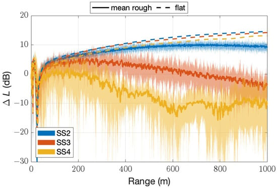
Figure 5.
Excess attenuation at 500 Hz for profiles corresponding to sea states 2, 3, and 4. See Figure 4. The thick continuous lines are the mean values, and the shaded areas depict the minimum and maximum predictions. The dashed lines are predictions for smooth surfaces with of sea states 2, 3, and 4.
The sound pressure level at the receiver, , at a distance r from a point source can be found as in the following Equation (22):
where is the SPL in a free field at 1 m from the source, the term accounts for the spherical spreading, [] is the air absorption, and represents the contribution of all additional mechanisms that can influence sound propagation. This last term, also called excess attenuation, can be expressed as a function of refraction caused by wind and temperature profiles, absorption and reflection of the shore, sea roughness, and turbulence. Excess attenuation, or SPL, relative to the free field is estimated using the following Equation (23):
where p is the complex acoustic pressure estimated accounting for surfaces, refraction, and turbulence, whereas is that estimated in a free field.
This paper is focused on estimating the contribution of sea roughness to . Throughout this work, wind is assumed to blow in the same direction of sound propagation from the source to the receiver. The effect of turbulence is neglected due to its limited contribution on sound propagation in a downward refracting atmosphere.
Sound propagation occurs over water only, and the source and receiver are placed at a 2 m height from the average surface elevation that is defined as 0 m. The sources considered in this work are Gaussian pulses with central frequencies [125, 250, 500, 1000, 2000 Hz]. The total length of the numerical domain is 1000 m, and the height is one-tenth of its length. This range is chosen as it represents the longest GTPE numerical domain with feasible computational times (less than an hour) on the machine used in this work for the highest acoustic frequency (2000 Hz). The domain has been divided into vertical and horizontal steps of one-tenth of the acoustic wavelength, . An absorbing layer is added outside the domain of interest to eliminate reflections from the upper numerical boundary [].
Ten sea profiles are generated for each sea state. Sound propagation is modeled above each profile for the frequencies of interest. The excess attenuation is predicted along the propagation range ten times for each sea state. A logarithmic average, as shown in Equation (24), is used to obtain the mean value of excess attenuation at each location [].
Examples of the resulting predictions in a refractive atmosphere over different sea states are shown in Figure 5.
Figure 5 shows that, given a sound speed profile, decreases when the surface is rough. Sea roughness introduces a noise mitigation effect that tends to increase with the sea state. In addition, the standard deviation of over ten predictions increases with an increasing sea state.
2.4. Equivalent Impedance Methods
To estimate the average noise mitigation effect due to a specific sea state using a GTPE solver is more computationally expensive than a single CNPE simulation. Specifically, the GTPE approach requires a continuous update of the discretized governing equation to account for the change in slope of the ground surface. This update occurs for every horizontal spatial step. In addition, in order to capture the average effect of a specific sea state, the simulation has to be repeated using several pseudorandom sea surfaces. The use of this method to predict SPL in real time over long distances (on the order of kilometers) is impractical. A computationally less intensive alternative is to use an equivalent impedance approach []. This method consists of replacing the rough surface with a flat absorbing surface that generates the same effect on the atmospheric sound propagation. An equivalent acoustic impedance accounts for an average effect of the surface roughness that includes the acoustic energy that is backscattered by the surface. In specific scenarios of downward refraction, part of this energy may be redirected forward. However, because the PE equation is a one-way wave equation from the source to the receiver [], this effect cannot be quantified.
Different approaches for estimating the equivalent impedance of a rough sea surface have been adopted by Boulanger and Attenborough [], Bolin et al. [,], and Van Renterghem et al. []. The method proposed by Boulanger and Attenborough is the same as that implemented in the work of Van Renterghem et al. However, the results from Boulanger and Attenborough are not used for comparison as they have been obtained using surfaces that are not derived from sea state spectra. The results of this work are compared with the experimental observations of Bolin et al. and with the results of Van Renterghem et al. A brief summary of these two is presented here.
Bolin et al.
The authors modeled the sea surface with a frequency-dependent equivalent impedance based on the Delany and Bazley model []. Sound propagation predictions obtained with a PE solver were compared to long range acoustic measurements (9 km of open water and 750 m of land). A constant effective flow resistivity of 3 × 10⁴ was chosen to represent rough water independently of the sea state [].
Van Renterghem et al.
The authors followed an approach similar to that of Boulanger and Attenborough []. A frequency-dependent equivalent impedance for sea states 2, 3, and 4 was numerically estimated. Pseudorandom sea surfaces were generated from PM sea spectra. Equivalent impedance was obtained using time domain simulations in which a broad frequency pulse was generated at a 0.5 m elevation from the rough surface. The receiver was located at a distance of 5 m at the same elevation as the source. The difference between direct and reflected sound fields was used to estimate a spherical reflection coefficient and, thus, an effective impedance.
The same experiment described in Van Renterghem et al. has been replicated by the authors of this work with a finite element method solver. Results comparable with those shown in the work of Van Renterghem et al. were found. However, the spectral peak for sea state 2 and larger corresponds to surface wavelengths greater than 5 m. For example, the dominant wavelength for a sea state 2 is about 8 m, and for a sea state 5, it is about 90 m. Thus, to better capture the contribution of longer sea wavelengths, the same sea surfaces were tested with a 20 m separation between the source and the receiver. The angle of incidence was kept constant by changing the elevation of the source and the receiver. This adjustment is also sufficient to avoid acoustic shadowing from waves with heights larger than the source and receiver elevation. Slightly larger values of a normalized effective surface impedance, , were found with this modified geometry. It should also be noted that this methodology generates some unphysical results for effective impedance (negative values of ) with both source–receiver separation distances. The same observation on this method was reported by Boulanger and Attenborough []. Negative values of are obtained for surface geometry such that the excess attenuation at the receiver is larger than 6 dB, and thus, the reflection coefficient is larger than unity. As a consequence, the cases that yield a negative real part of the effective impedance must be discarded. However, excess attenuation values larger than 6 dB are physically possible in cases of low frequencies (due to surface waves) or incoherent scattering. In fact, when the roughness scale is comparable with the acoustic wavelength, more than one ray could reach the receiver simultaneously. As a consequence, the method leads to an underestimation of the effective impedance. The Boulanger and Attenborough method implemented in the work of Van Renterghem et al. is valid when the acoustic wavelength is large in comparison to the roughness scale []. This condition is not met at all acoustic frequencies and sea states.
In this work, numerical predictions are used to estimate effective impedance as a function of sea state and frequency. Average excess attenuation predictions for each sea state, at a 2 m elevation, were obtained from a GTPE solver with a uniform effective speed of sound, as described in Section 2.3. The GTPE predictions for each sea state and acoustic frequency were compared with CNPE predictions over a flat absorbing surface in the same non-refractive atmosphere. The real and imaginary parts of the effective impedance used in a CNPE solver were varied in logarithmic steps. The difference between the CNPE predictions and the average of a set of GTPE predictions along the range was calculated. The impedance associated with the minimum difference in an excess attenuation was used as the seed for a minimization search algorithm. This two-stage search was needed as the function being minimized contains multiple local minima. Examples of this minimization process are shown in Section 3. Expressions of an effective surface impedance dependent on acoustic frequency and a significant wave height were found.
3. Results
Comparisons between the average excess attenuation in a non-refractive atmosphere from a GTPE solver and predictions obtained from a CNPE solver using the effective impedance found with the presented method are shown in Figure 6. The excess attenuation found using an equivalent impedance is in good agreement with those found using the GTPE at all frequencies and sea states. The effective impedances presented in this work, normalized to the acoustic impedance of air, are shown in the legend of Figure 6.
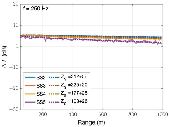
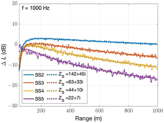
Figure 6.
Excess attenuation over sea states 2, 3, 4, and 5 in a non-refractive atmosphere. The thick continuous lines are the mean prediction obtained over a rough surface. The dotted lines are predictions for smooth surfaces with equivalent effective impedances corresponding to sea states 2, 3, 4, and 5. (Top) Acoustic frequency of 250 Hz; (Bottom) acoustic frequency of 1000 Hz.
Surface Impedance Parameterization
The effective impedance of rough sea is frequency and sea state dependent. It can be parameterized as follows:
where is the significant wave height in meters, f is the acoustic frequency in Hertz, and and are fitted parameters as reported in Table 1. The real part of in Equation (25) follows the form discussed in previous works [,]. The fitted parameters and clearly depend on the significant wave height. However, an effective parameterization of and over the significant wave height was not found, as small variations of the two parameters lead to significant deviations of the surface impedance .

Alternatively, the surface impedance can be parameterized as follows:
where the imaginary part is the same as in Equation (25). However, Equation (26) is only valid for values of larger than roughly 50. It should be noted that the imaginary part of is substantially smaller than the real part. The variability of the imaginary part of was not effectively captured in the parameterization. Due to comparatively small magnitude of , it is assumed constant with frequency in Equations (25) and (26). This assumption, if applied outside the frequency range studied in this work, may lead to cases where the imaginary part of exceeds the real part, contrary to results reported in this section. Figure 7 shows a comparison between the results of the minimization approach described in Section 2.4 and the parameterization summarized by Equations (25) and (26).
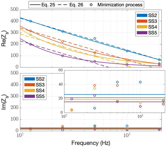
Figure 7.
Normalized effective surface impedance , real part (Top) and imaginary part (Bottom). The minimization results were obtained from the method of Section 2.4. A magnification of the imaginary part is also shown to better capture the difference between sea states.
4. Discussion
In Section 4.1, the authors first contextualize the equivalent impedances against other important previous results. In Section 4.2, the limits of the applicability of the equivalent impedance method in this work are discussed.
4.1. Comparing Equivalent Impedances with Prior Work
Figure 8 compares equivalent impedances obtained in this work with those reported by Bolin et al. [,] and Van Renterghem et al. []. Bolin et al. limited the analysis to discrete frequencies of 80, 200, and 400 Hz. The value of corresponding to 80 Hz is not reported in Figure 8, as it is outside the range of frequencies considered in this work. Additionally, the significant wave height was not measured during the experiments, and thus, the relative sea state is not reported in Figure 8. Real values of effective impedance used in Bolin et al. are comparable with those obtained in this work for a low sea state. The value of flow resistivity (3 × kg/s/m2) chosen in Bolin et al. corresponds to that of a highly reflective surface []. Effective impedance values presented in Bolin et al. are based on the Delany and Bazley model. The model provides an imaginary part of the effective impedance of the same order of magnitude as the real part, as well as non-physical results at low frequencies [,]. However, results obtained in this work show that the imaginary part of the effective impedance is generally much smaller than the real part. The study by Van Renterghem et al. reports on sea states from 2 to 4. As shown in Figure 8, the effective impedance estimated by Van Renterghem et al. is substantially smaller than that obtained in this work and those employed by Bolin et al. This discrepancy may be attributed to the underestimation of the effective surface impedance in the work of Van Renterghem et al., as discussed in Section 2.4.
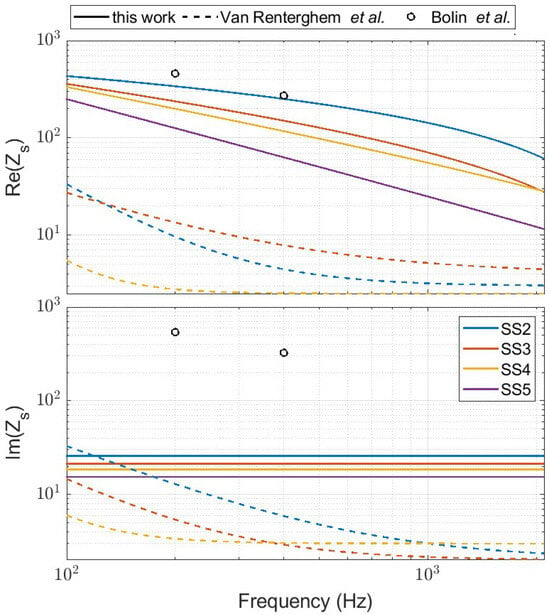
Figure 8.
Comparison between obtained in this work for non-refractive atmospheres along with results obtained by Bolin et al. [,] and Van Renterghem et al. []. Note that the y-axis is on a logarithmic scale.
4.2. Limitations of the Effective Impedance Method for Rough Sea Surfaces
Scattering from a rough surface can be of two types: coherent and incoherent. Coherent scattering, in the direction of specular reflection, is prevalent when the surface roughness scale is small compared with the acoustic wavelength. Incoherent scattering, in non-specular directions, dominates when the roughness scale is comparable with the acoustic wavelengths []. For the sea states considered in this work, the roughness varies from decimeters to a few meters, and the acoustic wavelengths are in the same range. Therefore, the dominant scattering is incoherent. While coherent scattering can be seen merely as a surface property and thus decoupled from any other effect, as it does not modify the main direction of the reflected rays, this decoupling is not true for incoherent scattering. In fact, the incoherent scattering depends on the source–receiver positioning and refraction. For this reason, effective surface impedance models presented in previous works are limited to surfaces that generate coherent scattering only [,].
The effective impedance estimated in the work of Van Renterghem et al. and those presented in this work (Figure 7) are based on the assumption that the equivalent impedance of the sea surface is a surface property only and, therefore, decoupled from refraction. In both cases, impedances are derived from numerical simulations in a non-refractive atmosphere and used to predict excess attenuation in a refractive atmosphere. The limitations of this assumption are studied in this section. A GTPE solver is able to predict excess attenuation accounting for surface roughness and refraction without decoupling the two effects. Averaged GTPE results are compared with predictions of a CNPE solver that uses the same refractive atmosphere and an effective surface impedance obtained in a non-refractive atmosphere.
Figure 9 shows excess attenuation predictions from a GTPE solver (solid line) for acoustic frequencies of 250 and 1000 Hz and sea states 2 to 5 with the corresponding profiles shown in Figure 4. Additionally, predictions from a CNPE solver that uses surface effective impedances derived from Equation (25) in the same refractive atmosphere are shown in dotted lines. The two predictions were in good agreement, within 2 dB, for some acoustic frequencies and sea states (see Figure 9, SS2 and SS3 at 250 Hz and SS3 at 1000 Hz). However, discrepancies of up to 10 dB were found in other cases (see Figure 9, SS5 at 250 Hz and SS2 at 1000 Hz). The results suggest that the use of an equivalent impedance for a sea surface that generates incoherent scattering can lead to prediction errors. The discrepancies can be overcome by applying a correction factor on the effective impedance. However, this correction factor must be a function of sea state, acoustic frequency, source–receiver geometry, and refraction. The use of this correction factor improves the accuracy of the predictions, at the expense of the generalization of a surface impedance dependent on sea state and frequency only.

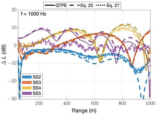
Figure 9.
Excess attenuation for profiles corresponding to sea states 2, 3, 4, and 5. The solid lines are the mean predictions obtained over a rough surface. The dashed and dotted lines are predictions for smooth surfaces with the same and effective impedance of Equation (25) (non-refractive) and Equation (27) (refractive), respectively. (Top) Acoustic frequency of 250 Hz; (Bottom) acoustic frequency of 1000 Hz.
A way to find the correction factor is to re-estimate the surface impedance in a refractive atmosphere, applying the method discussed in Section 2.4. The values of the surface impedance for the source and the receiver and a 2 m elevation and refraction condition shown in Figure 4 can be parameterized over a significant wave height, , and frequency, f, as in Equation (27).
The CNPE predictions obtained with the effective impedances from Equation (27) are shown in dotted lines in Figure 9. The use of instead of increases the accuracy of excess attenuation predictions. However, at a high frequency and a high sea state, e.g., SS5 at 1000 Hz, the equivalent impedance method fails to produce accurate predictions, highlighting the limits of this method for surface roughness exceeding the acoustic wavelength.
5. Conclusions
In this work, a method for generating pseudorandom sea surfaces consistent with a sea spectrum characteristic of a specific sea state is described. The pseudorandom sea surfaces can be incorporated in a GTPE solver to estimate the effect of roughness on atmospheric sound propagation. It should be noted that simulations used in this work are two-dimensional along the propagation path assuming that the acoustic propagation and primary wind direction are collinear.
A method for estimating acoustic surface impedance for sea states 2 to 5 is shown. Equivalent impedances can be numerically estimated by comparing sound propagation predictions obtained with a GTPE solver with those of a CNPE solver using an equivalent impedance. Effective surface impedances found in this work can be parameterized on the acoustic frequency and the significant wave height of the sea state.
Effective impedance methods are mostly limited to cases where a surface roughness scale is small compared with the acoustic wavelength. In those cases, the scattering is coherent, allowing the effective impedance to be considered an intrinsic property of the surface. However, this condition is not often met for the acoustic frequency range considered in this work, for which sea waves often generate incoherent scattering. This work investigates the limitations of using an effective impedance to emulate the effect of sea surface roughness in a refractive atmosphere. Results show that considering the effective impedance as a surface property can lead to prediction discrepancies that can exceed 10 dB. The use of an effective surface impedance correction factor that considers the refraction and source–receiver position substantially increases the accuracy of the predictions.
Author Contributions
Conceptualization, D.T. and A.V.; methodology, A.V.; software, D.T. and A.V.; validation, D.T., J.F.V., and A.V.; investigation, D.T., J.F.V., T.J.R., and A.V.; writing—original draft preparation, T.J.R. and A.V.; writing—review and editing, D.T., J.F.V., T.J.R., and A.V.; supervision, D.T. and J.F.V.; funding acquisition, D.T. and T.J.R. All authors have read and agreed to the published version of the manuscript.
Funding
This work is supported by the Office of Naval Research Awards N00014-21-1-2059, N00014-21-1-2930, and N00014-22-1-2492.
Data Availability Statement
The original contributions presented in the study are included in the article, further inquiries can be directed to the corresponding authors.
Conflicts of Interest
The authors declare no conflicts of interest.
Abbreviations
The following abbreviations are used in this manuscript:
| CNPE | Crank–Nicolson parabolic equation |
| ECKV | Elfouhaily, Chapron, Katsaros, Vandemark |
| FDTD | Finite Difference Time Domain |
| GFPE | Green’s Function parabolic equation |
| MABL | marine atmospheric boundary layer |
| MOST | Monin–Obukhov similarity theory |
| PE | parabolic equation |
| PM | Pierson–Moskowitz |
References
- Swearingen, M.E.; White, M.J.; Guertin, P.J.; Albert, D.G.; Tunick, A. Influence of a forest edge on acoustical propagation: Experimental results. J. Acoust. Soc. Am. 2013, 133, 2566–2575. [Google Scholar] [CrossRef] [PubMed]
- Cheinet, S.; Cosnefroy, M.; Königstein, F.; Rickert, W.; Christoph, M.; Collier, S.L.; Dagallier, A.; Ehrhardt, L.; Ostashev, V.E.; Stefanovic, A.; et al. An experimental study of the atmospheric-driven variability of impulse sounds. J. Acoust. Soc. Am. 2018, 144, 822–840. [Google Scholar] [CrossRef] [PubMed]
- Ostashev, V.E.; Wilson, D.K.; Muhlestein, M.B. Wave and extra-wide-angle parabolic equations for sound propagation in a moving atmosphere. J. Acoust. Soc. Am. 2020, 147, 3969–3984. [Google Scholar] [CrossRef]
- Guibard, A.; Sèbe, F.; Dragna, D.; Ollivier, S. Influence of meteorological conditions and topography on the active space of mountain birds assessed by a wave-based sound propagation model. J. Acoust. Soc. Am. 2022, 151, 3703–3718. [Google Scholar] [CrossRef] [PubMed]
- Vecchiotti, A.; Ryan, T.J.; Cobb, F.A.; Vignola, J.F.; Turo, D. Investigation of engineering models for sound propagation in a near-shore environment. Appl. Acoust. 2022, 199, 108991. [Google Scholar] [CrossRef]
- Bolin, K.; Boué, M.; Karasalo, I. Long range sound propagation over a sea surface. J. Acoust. Soc. Am. 2009, 126, 2191–2197. [Google Scholar] [CrossRef] [PubMed]
- Bolin, K.; Almgren, M.; Ohlsson, E.; Karasalo, I. Long term estimations of low frequency noise levels over water from an off-shore wind farm. J. Acoust. Soc. Am. 2014, 135, 1106–1114. [Google Scholar] [CrossRef] [PubMed]
- Van Renterghem, T.; Botteldooren, D.; Dekoninck, L. Airborne sound propagation over sea during offshore wind farm piling. J. Acoust. Soc. Am. 2014, 135, 599–609. [Google Scholar] [CrossRef]
- Konishi, K.; Maekawa, Z. Interpretation of long term data measured continuously on long range sound propagation over sea surfaces. Appl. Acoust. 2001, 62, 1183–1210. [Google Scholar] [CrossRef]
- Attenborough, K.; Li, K.M.; Horoshenkov, K.V. Predicting Outdoor Sound; Taylor & Francis: Abingdon, UK, 2007. [Google Scholar]
- Salomons, E.M. Computational Atmospheric Acoustics, 1st ed.; Springer: Berlin/Heidelberg, Germany, 2001. [Google Scholar]
- Ostashev, V.; Wilson, D. Acoustics in Moving Inhomogeneous Media; Taylor & Francis: Abingdon, UK, 2015. [Google Scholar]
- Gilbert, K.E.; White, M.J. Application of the parabolic equation to sound propagation in a refracting atmosphere. J. Acoust. Soc. Am. 1989, 85, 630–637. [Google Scholar] [CrossRef]
- Gilbert, K.E.; Di, X. A fast Green’s function method for one-way sound propagation in the atmosphere. J. Acoust. Soc. Am. 1993, 94, 2343–2352. [Google Scholar] [CrossRef]
- Beilis, A.; Tappert, F.D. Coupled mode analysis of multiple rough surface scattering. J. Acoust. Soc. Am. 1979, 66, 811–826. [Google Scholar] [CrossRef]
- Parakkal, S.; Gilbert, K.E.; Di, X. Application of the Beilis–Tappert parabolic equation method to sound propagation over irregular terrain. J. Acoust. Soc. Am. 2012, 131, 1039–1046. [Google Scholar] [CrossRef] [PubMed]
- Sack, R.A.; West, M. A parabolic equation for sound propagation in two dimensions over any smooth terrain profile: The generalised terrain parabolic equation (GT-PE). Appl. Acoust. 1995, 45, 113–129. [Google Scholar] [CrossRef]
- Jones, A.D.; Duncan, A.; Maggi, A.; Bartel, D.; Zinoviev, A. A Detailed Comparison Between a Small-Slope Model of Acoustical Scattering From a Rough Sea Surface and Stochastic Modeling of the Coherent Surface Loss. IEEE J. Ocean. Eng. 2016, 41, 689–708. [Google Scholar] [CrossRef]
- Delany, M.; Bazley, E. Acoustical properties of fibrous absorbent materials. Appl. Acoust. 1970, 3, 105–116. [Google Scholar] [CrossRef]
- Boulanger, P.; Attenborough, K. Effective impedance spectra for predicting rough sea effects on atmospheric impulsive sounds. J. Acoust. Soc. Am. 2005, 117, 751–762. [Google Scholar] [CrossRef]
- Pierson, W.J.; Moskowitz, L. A proposed spectral form for fully developed wind seas based on the similarity theory of S. A. Kitaigorodskii. J. Geophys. Res. 1964, 69, 5181–5190. [Google Scholar] [CrossRef]
- Hasselmann, D.E.; Dunckel, M.; Ewing, J.A. Directional Wave Spectra Observed during JONSWAP 1973. J. Phys. Oceanogr. 1980, 10, 1264–1280. [Google Scholar] [CrossRef]
- Elfouhaily, T.; Chapron, B.; Katsaros, K.; Vandemark, D. A Unified Directional Spectrum for Long and Short Wind-Driven Waves. J. Geophys. Res. 1997, 102, 15781–15796. [Google Scholar] [CrossRef]
- Thorsos, E.I. Acoustic scattering from a Pierson–Moskowitz sea surface. J. Acoust. Soc. Am. 1990, 88, 335–349. [Google Scholar] [CrossRef]
- Alves, J.H.G.M.; Banner, M.L.; Young, I.R. Revisiting the Pierson–Moskowitz Asymptotic Limits for Fully Developed Wind Waves. J. Phys. Oceanogr. 2003, 33, 1301–1323. [Google Scholar] [CrossRef]
- Phillips, O.M. The Dynamics of the Upper Ocean, 2nd ed.; Cambridge University Press: Cambridge, UK, 1980. [Google Scholar]
- Wu, J. Wind-Stress coefficients over Sea surface near Neutral Conditions—A Revisit. J. Phys. Oceanogr. 1980, 10, 727–740. [Google Scholar] [CrossRef]
- Mobley, C.D.; Boss, E.; Roesler, C. Ocean Optics Web Book. Available online: https://www.oceanopticsbook.info/ (accessed on 7 November 2023).
- Kay, S.; Hedley, J.; Lavender, S.; Nimmo-Smith, A. Light transfer at the ocean surface modeled using high resolution sea surface realizations. Opt. Express 2011, 19, 6493–6504. [Google Scholar] [CrossRef] [PubMed]
- Barltrop, N.D.P.; Adams, A.J. Dynamics of Fixed Marine Structures, 3rd ed.; Butterworth-Heinemann: Oxford, UK, 1991; pp. 249–344. [Google Scholar]
- Foken, T. 50 Years of the Monin–Obukhov Similarity Theory. Bound.-Layer Meteorol. 2006, 119, 431–447. [Google Scholar] [CrossRef]
- Garratt, J.R. The Atmospheric Boundary Layer; Cambridge University Press: Cambridge, UK, 1994. [Google Scholar]
- L’Espérance, A.; Nicolas, J.; Wilson, D.K.; Thomson, D.W.; Gabillet, Y.; Daigle, G. Sound propagation in the atmospheric surface layer: Comparison of experiment with FFP predictions. Appl. Acoust. 1993, 40, 325–346. [Google Scholar] [CrossRef]
- Rossing, T. Springer Handbook of Acoustics; Springer Sciences+Business: New York, NY, USA, 2007. [Google Scholar]
- Edson, J.B.; Fairall, C.W. Similarity Relationships in the Marine Atmospheric Surface Layer for Terms in the TKE and Scalar Variance Budgets. J. Atmos. Sci. 1998, 55, 2311–2328. [Google Scholar] [CrossRef]
- Archer, C.L.; Colle, B.A.; Veron, D.L.; Veron, F.; Sienkiewicz, M.J. On the predominance of unstable atmospheric conditions in the marine boundary layer offshore of the U.S. northeastern coast. J. Geophys. Res. Atmos. 2016, 121, 8869–8885. [Google Scholar] [CrossRef]
- Charnock, H. Wind stress on a water surface. Q. J. R. Meteorol. Soc. 1955, 81, 639–640. [Google Scholar] [CrossRef]
- Garratt, J.R. Review of Drag Coefficients over Oceans and Continents. Mon. Weather. Rev. 1977, 105, 915–929. [Google Scholar] [CrossRef]
- Dyer, A.J. A review of flux-profile relationships. Bound.-Layer Meteorol. 1974, 7, 363–372. [Google Scholar] [CrossRef]
- Paulson, C.A. The Mathematical Representation of Wind Speed and Temperature Profiles in the Unstable Atmospheric Surface Layer. J. Appl. Meteorol. Climatol. 1970, 9, 857–861. [Google Scholar] [CrossRef]
- Roberts, J.B.; Clayson, C.A.; Robertson, F.R. SeaFlux Data Products; Type: Dataset; The NASA Global Hydrology Resource Center DAAC: Huntsville, AL, USA, 2020. [Google Scholar] [CrossRef]
- Bass, H.E.; Sutherland, L.C.; Zuckerwar, A.J.; Blackstock, D.T.; Hester, D.M. Atmospheric absorption of sound: Further developments. J. Acoust. Soc. Am. 1995, 97, 680–683. [Google Scholar] [CrossRef]
- Kirby, R. On the modification of Delany and Bazley fomulae. Appl. Acoust. 2014, 86, 47–49. [Google Scholar] [CrossRef]
- Dragna, D.; Attenborough, K.; Blanc-Benon, P. On the inadvisability of using single parameter impedance models for representing the acoustical properties of ground surfaces. J. Acoust. Soc. Am. 2015, 138, 2399–2413. [Google Scholar] [CrossRef]
Disclaimer/Publisher’s Note: The statements, opinions and data contained in all publications are solely those of the individual author(s) and contributor(s) and not of MDPI and/or the editor(s). MDPI and/or the editor(s) disclaim responsibility for any injury to people or property resulting from any ideas, methods, instructions or products referred to in the content. |
© 2024 by the authors. Licensee MDPI, Basel, Switzerland. This article is an open access article distributed under the terms and conditions of the Creative Commons Attribution (CC BY) license (https://creativecommons.org/licenses/by/4.0/).