Article

Sound Pressure Level Analysis of a Liquid-Fueled Lean Premixed Swirl Burner with Various Quarls

Department of Energy Engineering, Faculty of Mechanical Engineering, Budapest University of Technology and Economics, Műegyetem rkp. 3., 1111 Budapest, Hungary
*
Author to whom correspondence should be addressed.
Acoustics 2020, 2(1), 131-146; https://doi.org/10.3390/acoustics2010010
Submission received: 3 October 2019 / Revised: 14 February 2020 / Accepted: 17 February 2020 / Published: 1 March 2020
(This article belongs to the Special Issue Acoustical Materials)

Abstract

:
Swirl burners are widely used in numerous practical applications since they are characterized by low pollutant emission and a wide operating range. Besides reliable operation, a burner must fulfill noise emission regulations, which is often a sound pressure level in dB(A) when people are affected. Therefore, the present paper evaluates the overall sound pressure level (OASPL) variation of a 15-kW liquid-fueled turbulent atmospheric swirl burner at various setups. Firstly, the combustion air flow rate was adjusted, which induced a swirl number modification due to the fixed swirl vanes. Secondly, the atomizing pressure of the plain-jet airblast atomizer was modified, which also affected the swirl number. High atomizing air jets notably increased combustion noise by intensifying the shear layer. Thirdly, a geometrical modification was performed; 0°–60° half cone angle quarls in 15° steps were installed on the lip of the baseline burner for extended flame stability. By filtering the OASPL to the V-shaped flames, a linearly decreasing trend was observed as a function of swirl number. Their derivative also has a linearly decreasing characteristic as a function of the atomizing pressure.

Graphical Abstract

1. Introduction

Premixed swirl combustion in V-shaped mode is widely used in steady-operating industrial combustion chambers to fulfill emission standards [1,2]. The leaner the flame, the lower is the emission of nitrogen oxides (NOX); thus, the operation of the combustion chamber lies close to the flame blowout by design [3,4]. Consequently, a high understanding of combustion dynamics, especially thermo-acoustic oscillations [5], is required to prevent operational failures [6]. There are numerous papers available on the investigation of blowout using various time series analyses [7,8,9]. Typically, OH* and/or acoustic measurements are performed to detect oscillations at a few hundred Hz, which characterizes the flame in V-shaped mode. Their relative intensity is monitored, which shows an increase prior to blowout [6,10]. The majority of acoustical studies focus on common fossil fuels; however, it was shown earlier that stability limits are significantly affected by fuel type and combustion conditions [11]. By installing a quarl on the burner, the stable operating regime can be significantly extended [12]; hence, burner design is investigated in great detail in this paper.
Besides pollutant emission regulations, acoustic emission is also significant [13,14]. Power plants and airports that were built outside of major cities a couple of decades ago belong to suburban regions now [15]. Therefore, operational noise has to be minimized [16,17]. In the case of aviation engines, the contribution of combustion noise is notable at full thrust during takeoff [18,19]. Even though advanced airfoils with porous trailing edges can reduce airfoil noise [20], combustion is still a notable part of the acoustic emission [21]. Combustion noise usually consists of a broadband spectrum without sharp peaks. However, V-shaped flames are characterized by frequencies in the range of a few hundred Hz, which tend to decrease as the operation becomes leaner [6]. The theoretical interaction between turbulence and combustion was described by Clavin and Siggia [22]. It is an important observation that as the A-weighting [23] provides a negative gain up to 1 kHz, a positive gain follows it in the 1–6 kHz range. Above 6 kHz, the gain is also negative. Even though the gain of the human ear is slightly different from A-weighting [24], the agreement is close enough to use it in international noise regulations [25,26,27,28]. Interestingly, the threshold values in standards and directives are given in the overall sound pressure level (OASPL), the spectral composition of the source is omitted. The OASPL is the total energy contained in the spectrum, usually normalized to a reference pressure of 20 mPa, which is also used in the present study. Since liquid fuel was combusted presently and a plain-jet airblast atomizer was used, the high-velocity shear is a governing factor in the resulting combustion noise. Acoustical characteristics of a similar free jet were discussed by Freund [29] under cold conditions. The directional dependence of such an acoustic source was described by Bailly et al. [30]. Combustion acoustics and its modeling was excellently reviewed by Candel et al. [31].
To date, numerical prediction of combustion noise is available, however, it is limited to simple fuels and burner configurations and is computationally expensive as it requires direct numerical simulation [32,33]. Speth and Ghoniem [34] discussed the OASPL of syngas combustion in the composition range of 20%–80% by CO under lean conditions to evaluate the operation modes of their swirl-stabilized burner. Methane and ethane fuel-rich non-swirl flames diluted with hydrogen were investigated by Singh et al. [35] with the result of linear correlation between OASPL-Mach number and air-to-fuel equivalence ratio-Mach number trends. It is known that fuel-rich mixtures are characterized by increased noise compared to lean combustion, and the OASPL peak is located near the stoichiometric condition [36]. Swirl vanes are widely used in combustion technology; however, they are also excellent for noise suppression of supersonic free jets [37,38]. Apart from pure hydrocarbon flames, Shanbhogue et al. [39] investigated the extinction strain of various methane-hydrogen mixtures. The elevated hydrogen content allowed a wider stability range and resulted in a slightly reduced combustion noise. The OASPL was also found to be a good indicator of flame stability of a propane step burner with hydrogen dilution [40,41].
The present paper investigates the OASPL of a lean premixed swirl burner equipped with an airblast atomizer. Since atomization is governed by atomizing air pressure, it allows a semi-flexible operation as it can be adjusted almost freely to provide the desired spray quality with low dependence on the fuel flow rate. This was the reason why airblast atomizers were developed [42]. In order to compare burner geometries, various quarls were applied on the burner, which alters the blowout stability of the flame. The OASPL trends were evaluated by using a wide parameter matrix, focusing principally on V-shaped flames.

2. Materials and Methods

Firstly, the combustion test rig is discussed, emphasizing on the acoustic setup to provide a general overview of the measurement system. Secondly, the estimated atomization characteristics and fuel properties are presented, highlighting the atomizing free jet, which greatly influences the swirling flow in the mixing tube (discussed in the last subsection).

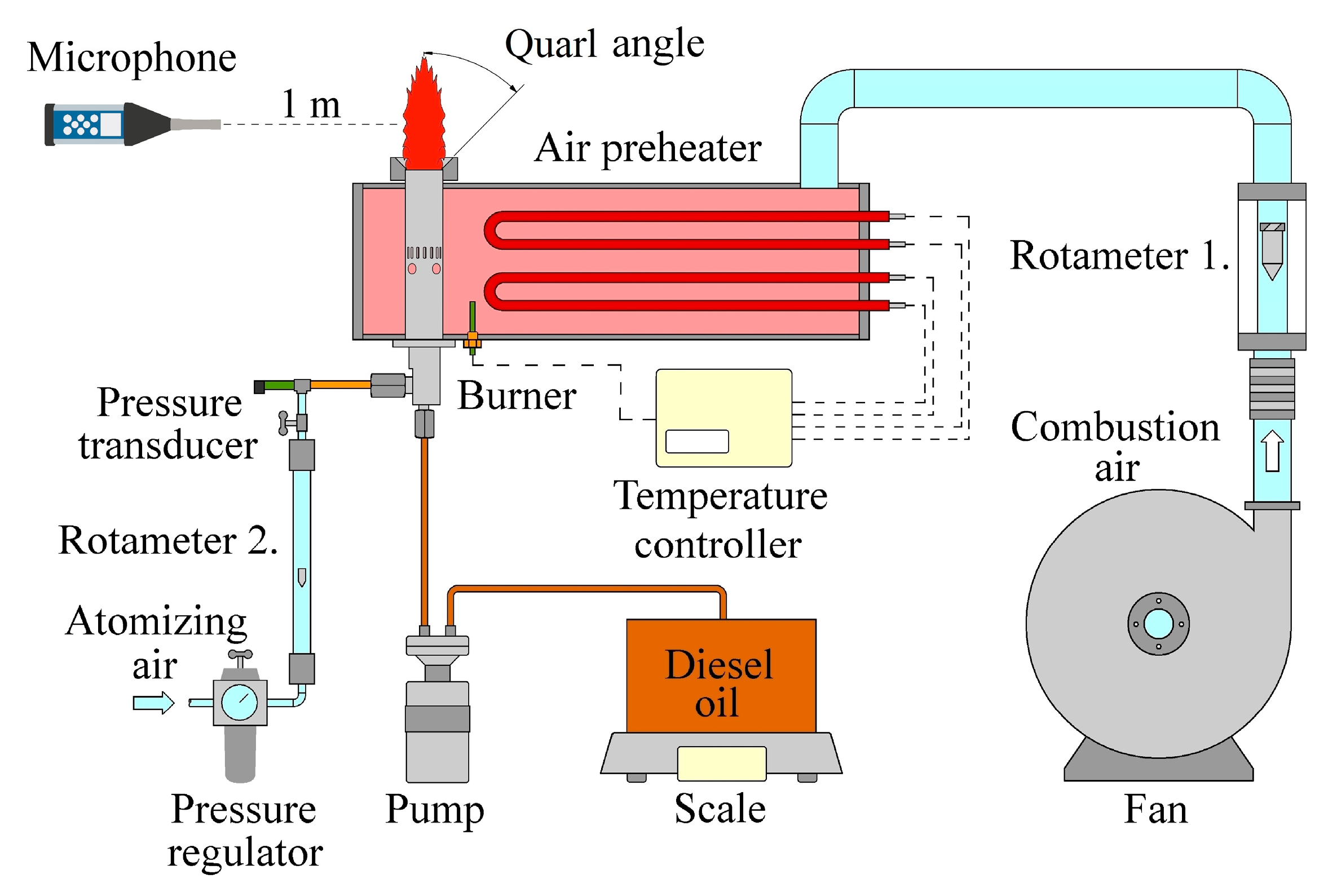
2.1. Experimental Setup

Figure 1 shows the atmospheric test rig with the installed burner, which is detailed in Section 2.2. The combustion air was delivered by a frequency inverter-controlled fan, and flow rate measured by a rotameter. Then, a PID-controlled preheater (HAGA Kft., Budapest, Hungary) increased the air temperature to 400 °C before entering the burner. Over the course of the measurements, the combustion air flow rate increased from 11.9 kg/h until blowout in 2.38 kg/h steps in all setups, which meant 2 m3/h steps in rotameter reading. Since the atomizing air flow rate can be calculated using an adiabatic expansion at the atomizer nozzle [43], the second rotameter was used only for validation.
The air-to-fuel equivalence ratio, λ, was varied in the range of 0.7–2. Note that it refers to primary λ, and the rest of the air was used from the atmosphere for complete combustion. λ is defined by Equation (1):
λ = m ˙ a i r / m ˙ a i r , s t o ,
where m ˙ a i r is the actual sum of combustion air plus atomizing air flow rates and m ˙ a i r , s t o refers to the air mass flow rate required for stoichiometric combustion. The burner without a quarl is referred to as the baseline. When quarls were applied, they were put directly to the burner lip, detailed in Section 2.2. All variants had 16 mm slant height, while the half cone angle varied from 0° to 60° in 15° steps. The setups mentioned later are referred by their quarl half cone angle. The corresponding pollutant emission analysis was discussed in a previous paper [12]; consequently, it is omitted now.
A SVAN 971-type sound analyzer (SVANTEK, Warsaw, Poland) was used for the acoustic measurement and placed 1 m from the burner axis at the same height as the burner lip. The data acquisition frequency was 12 kHz, which is enough for capturing the typical combustion-related noise in rich detail [44]. The sensitivity of the prepolarized 1/2”, 1st class ACO 7052E condenser microphone was 28.74 mV/Pa. The device was automatically calibrated with an SV33 calibrator (114 dB at 1 kHz, complies with the IEC 60942:2003 standard, SVANTEK). For data evaluation, its dedicated software, the SvanPC++ (version 3.1.5, SVANTEK), was used. The software calculations were verified by Matlab scripts at several randomly selected measurement points, using raw sound files. The recording was continuous from ignition until blowout. However, at least 30 s combustion noise was recorded at each measurement condition after reaching the steady-state operation of the corresponding setup. The relative standard deviation of the OASPL over 30 s varied between 1% and 5.6%, depending on the operational parameters. Fourteen percent relative standard deviation was calculated at two measurement points of the 0° quarl near the critical swirl number, which is discussed later in this section. For the spectral analysis, a window size of 1024 samples was used with no overlap. All the 30 s acoustic measurements took place after at least 30 s warm-up time upon setting the desired conditions. This time frame was adequate for the burner to reach its corresponding steady-state temperature. However, the OASPL was principally governed by the highly intense shear generated by the high-velocity atomizing annular jet.
The host environment of the test rig was a heat engine laboratory where this device shared the room with gas turbines and boilers which did not operate during the acoustic measurements. The walls contained several utility pipes, including electricity, water, natural gas, and the exhaust system. The stairs and several cabinets made the acoustic environment even more complex. Consequently, neither single frequency-amplitude pairs nor accurate OASPL measurement was claimed in this paper.

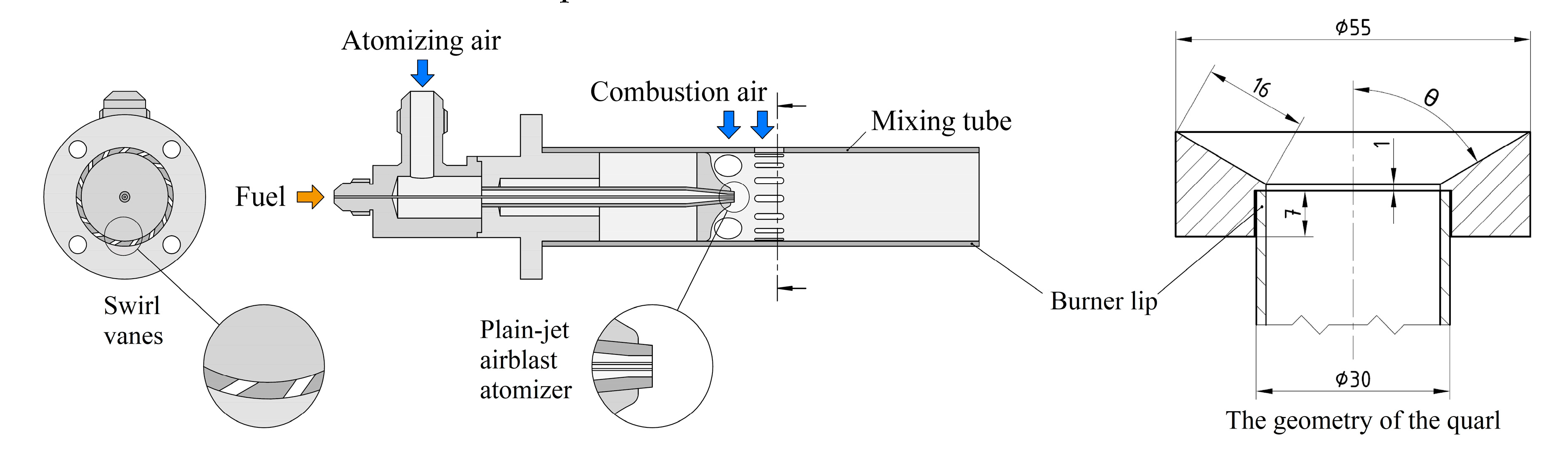
2.2. Burner Design and Atomization

The investigated lean premixed prevaporizing-type burner is shown in Figure 2, featuring its swirl vanes and the plain-jet airblast atomizer, and the general design of the used quarls. It has a central d0 = 0.4 mm inner diameter fuel pipe, and the atomizing air is accelerated in a concentric annular nozzle (0.8 mm inner and 1.6 mm outer diameter). The mixing tube is 75.5 mm long, measured from the atomizer tip, and its inner radius is R = 13.4 mm. In this study, the atomizing gauge pressure, pg, was varied from 0.3 to 1.6 bar. The uncertainty of pressure measurement was below 1 kPa. The burner was used in a Capstone C30 micro gas turbine while the quarls were manufactured in the local workshop.
In combustion technology, the spray is usually characterized by surface-to-volume mean diameter, SMD, which influences combustion stability and pollutant emissions [3,45]. Since a generally applicable estimation of the atomization process is presently unknown, the literature contains numerous empirical formulae to determine the SMD of an atomizer design [46]. In a preceding work, it was proven that a modified formula of Lefebvre [47] characterized accurately the SMD of the used airblast atomizer, shown by Equation (2) [48]:
S M D = 0.66 · d 0 · W e A 0.5 ( 1 + 1 / A F R )
where AFR is the air-to-fuel mass flow ratio of the atomizer and WeA is the Weber number of the atomizing air as follows:
W e A = ρ A · w A 2 · d 0 / σ ,
where ρA is the density of atomizing air at the nozzle, wA is the atomizing air discharge velocity, and σ is the surface tension of the utilized standard diesel oil (EN 590:2014). Table 1 summarizes the principal parameters of atomization, considering a constant fuel flow rate since the combustion power was uniformly 15 kW for all the cases. Ma = a/wA is the Mach number, where a is the speed of sound of the fully expanded jet. The notable fuel properties are summarized in Table 2.

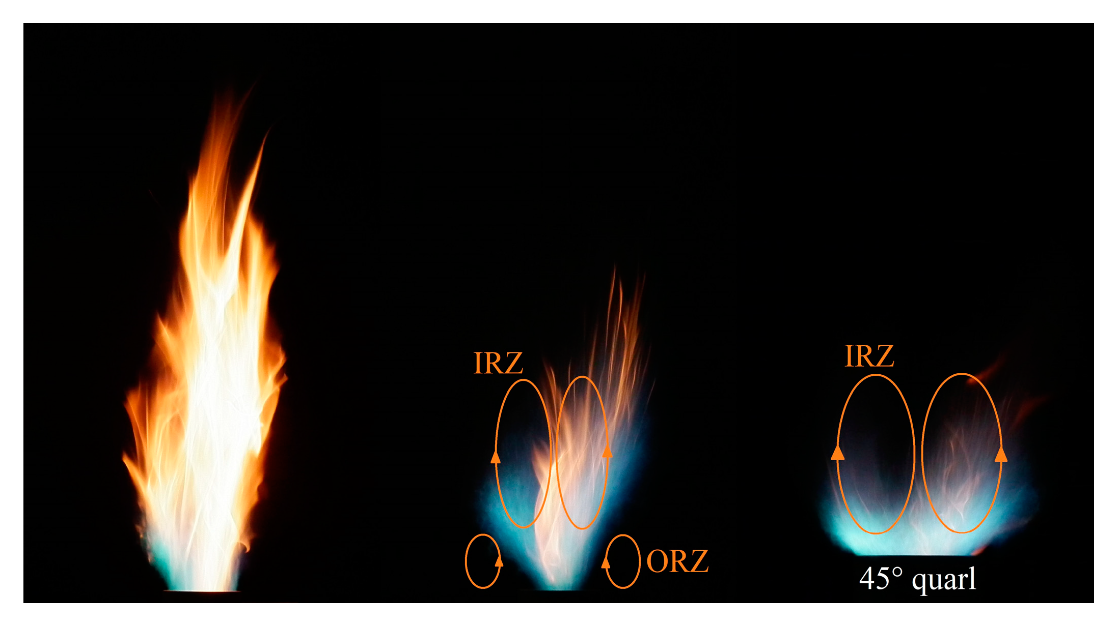
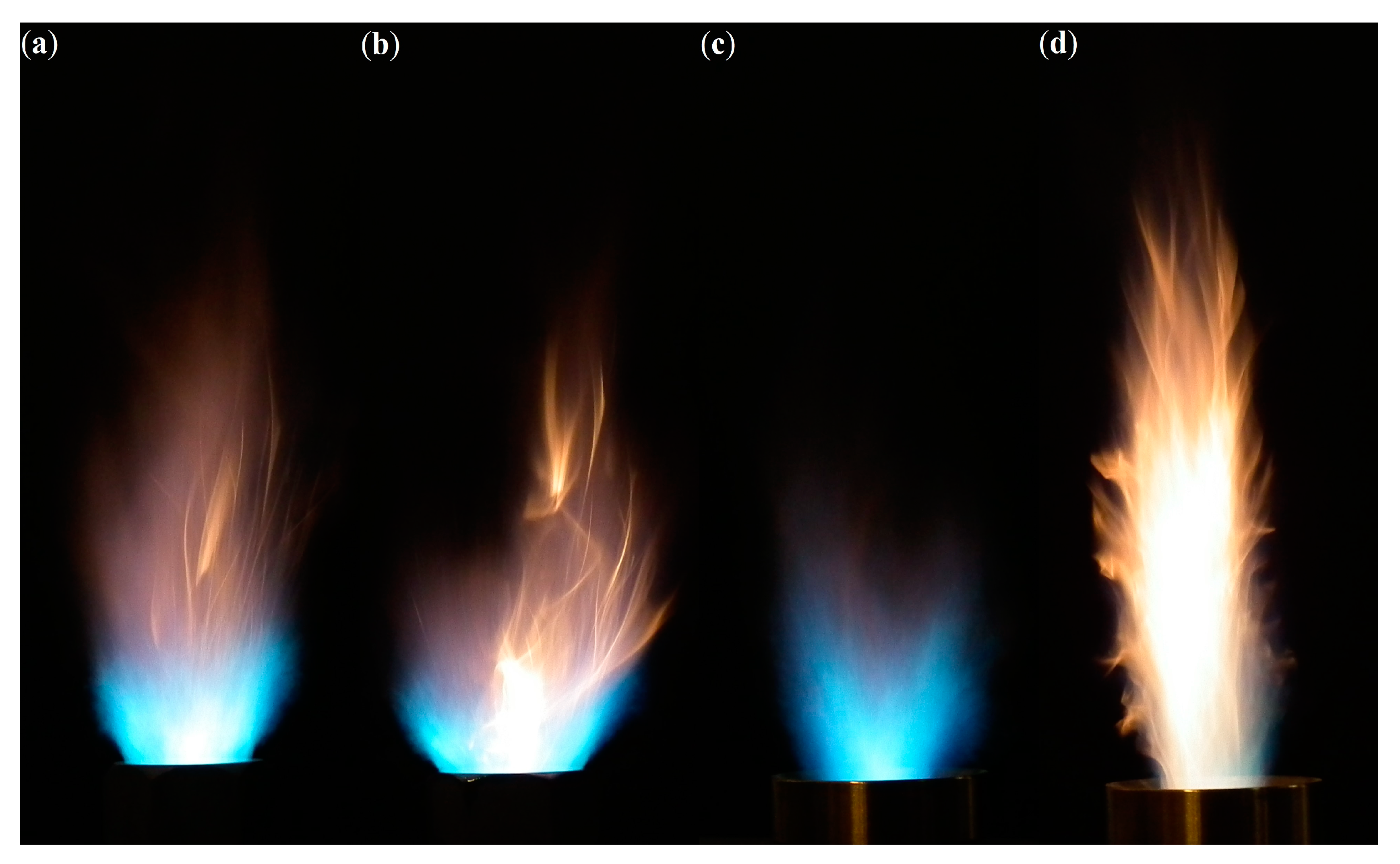
2.3. Swirl Characterization and Observed Flames

The burner has four radial, and fifteen fixed 45° slots; hence, swirling flow is generated at the inlet. The corresponding dimensionless quantity is the swirl number, introduced by Beér and Chigier [49]:
S = G φ / ( G x R ) ,
where Gφ is the axial flux of the angular momentum, Gx is the axial thrust, and R is the radius of the mixing tube. By assuming the conservation of momentum, the geometric swirl number is usually calculated by Equation (5), based on the inlet conditions of the burner [49] since the spatial distribution of the pressure and velocity of the burner is rarely available in practice:
S = G φ / ( G x R ) ,
where S’ is the geometric swirl number. G’x is the thrust at the inlet; hence, the pressure field can be omitted, and average velocity can be used for S’ estimation. This calculation method of the geometric swirl number was criticized by, e.g., Galley et al. [50], and Durox et al. [9]. Nevertheless, the cited results are limited for a different burner, and its generalization to the present burner is not possible. Hence, Equation (5) is used as the definition of the swirl number. Since the swirl vanes were fixed, the swirl number varied with the combustion air flow rate. The axial thrust is significantly increased by the increasing atomizing air flow rate at elevated pg, leading to low S’. G’x was calculated by Equation (6):
G x = m ˙ C · w C + m ˙ A · w A + m ˙ F · w F ,
where subscripts C and F refer to combustion air and fuel, respectively. Gφ is estimated as:
G φ = 1 1 ψ · tan ( α ) 1 + tan ( α ) · tan ( π / z ) · m ˙ φ 2 ρ C · 2 · π · B ,
where α = 45° is the swirl vane angle, z = 15 is the number of swirl slots, B = 8.8 mm is the height of the swirl slots, ρC = 0.52 kg/m3 is the density of combustion air, and
m ˙ φ = A · m ˙ C is the mass flow rate passing through the swirl vanes. A is the area ratio of the two inlet types since the pressure drop across them was negligible. Hence, A = h · B · z / ( h · B · z + y · D 2 · π / 4 ) = 0.44 , where h = 1.2 mm is the width of the swirl slots, y = 4 is the number of circular slots with D = 8 mm diameter. The blockage factor, ψ, is calculated as follows:
ψ = z · s 2 · π · R · cos ( α ) ,
where s = 3.3 mm is the slot-to-slot distance in the circumference, understood as the width of the metal blockage.
Depending on the swirl number, two regimes and a transitory zone between them can be distinguished. At low S’, the flame is straight. At S’ ~ 0.52, the flame enters a transitory regime where both straight and V-shape are observable with a random alteration between them. Above S’ ~ 0.81, a stable V-shaped flame develops. The mentioned S’ values for the geometric swirl number correspond to the baseline burner, which is only slightly affected by the quarls. The mentioned flame shapes are presented in Figure 3. Even though there are visible flares, the majority of the droplets evaporate inside the mixing tube, according to our previous work [43]. Notable flares were only observed in the λ < 1 range. The straight flame has a helical flow structure, shown by the twisted flares. Both the Inner Recirculation Zone (IRZ) and the Outer Recirculation Zone (ORZ) were indicated in the case of V-shaped flames. A significant portion of the ORZ is occupied and hence substituted by the 45° quarl on the right image.
The Reynolds number, Re, of the fuel-air mixture was calculated by Equation (9), considering the vaporization of the liquid fuel droplets and its mixing with the expanded atomizing air and the preheated combustion air. It was assumed that there is no flashback, which would otherwise increase Re.
R e = w x · 2 · R · ρ x / μ x ,
where wx is the mixture discharge velocity at the mixing tube outlet. ρx is the density of the mixture, and µx is its dynamic viscosity. The Reynolds number values varied between 6800 and 18680; therefore, the combustion was always in the turbulent regime.

3. Results and Discussion

This section starts with the discussion of the spectral characteristics of the investigated burner to understand the results of the OASPL analysis better, including the typical noise pattern of the various flame shapes. Secondly, the OASPL is discussed at pg = 0.3 bar, highlighting the characteristic effect of the combustion air flow rate on the combustion noise. Thirdly, the effect of the combustion air flow rate on OASPL with Z-weighting is analyzed, emphasizing the V-shaped flames. Lastly, the trends in the previous results are combined to conclude a general noise emission characteristic of the investigated swirl burner.

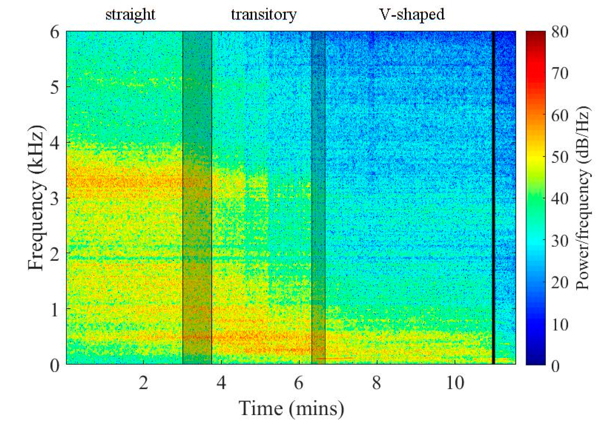
3.1. Spectral Analysis of the Flame

Initially, the combustion air flow rate was low, which resulted in a straight flame at pg = 0.3 bar with S’ = 0.48. The increase in combustion air flow rate, hence, in tangential momentum due to the fixed 45° swirl vanes, led to a random breakdown and merging of the precessing vortex core, called the transitory regime. A stable, V-shaped flame was then observable until blowout, shown in Figure 4. Note that certain setups reached neither the transitory state nor the subsequent V-shaped operation. They were the ones with high atomizing pressures and quarls, which provided no or low effect on flame stability. The spectrum of the straight flame was dominated by frequencies between 3 and 4 kHz. This band starts to fade as the flame approaches the transitory regime with the increasing combustion air flow rate, and hence S’. By increasing the air flow rate further, the average occurrence ratio of the two flame shapes starts to tend to the V-shaped flame; therefore, the amplitude at > 3 kHz decreases and low-frequency bands start to emerge, especially at 500 and 220 Hz. The V-shaped regime is characterized by lower amplitudes, and the energy density of the reacting flow is concentrated into the sub-1 kHz regime until blowout and contains no peak in the 3–4 kHz band.
Since the V-shaped flame will be evaluated in the following subsections, it was crucial to define where exactly the V-shaped regime starts. Presently, the mentioned high and low-frequency bands were checked. When only high-frequency components were present in the 30 s signal, the flame was classified as a straight flame; if a mixture of the bands was found in the spectrum, it was the transitory regime. With solely low-frequency components, the flame is called V-shaped. Note that there was no M-shaped flame observed. Singh et al. [44,51] report that the combustion-related noise is concentrated below 1.5 kHz, which is in line with the present spectrum in the V-shaped regime, compared to the spectrum of the blowout. However, this statement fails for the straight flames in the present case. Due to the increase in combustion air flow rate, and hence in λ, the amplitudes of characteristic frequency bands start to decrease, while the rest of the spectrum remains similar. Considering the A-weighting function, shown in Figure 5, it becomes evident that the shift in characteristic frequencies alone results in lower OASPL, if straight and V-shaped flames are compared. Also, the leaner operation further reduces combustion noise. As a consequence, lean V-shaped flames mean a decreased physiological exposure.

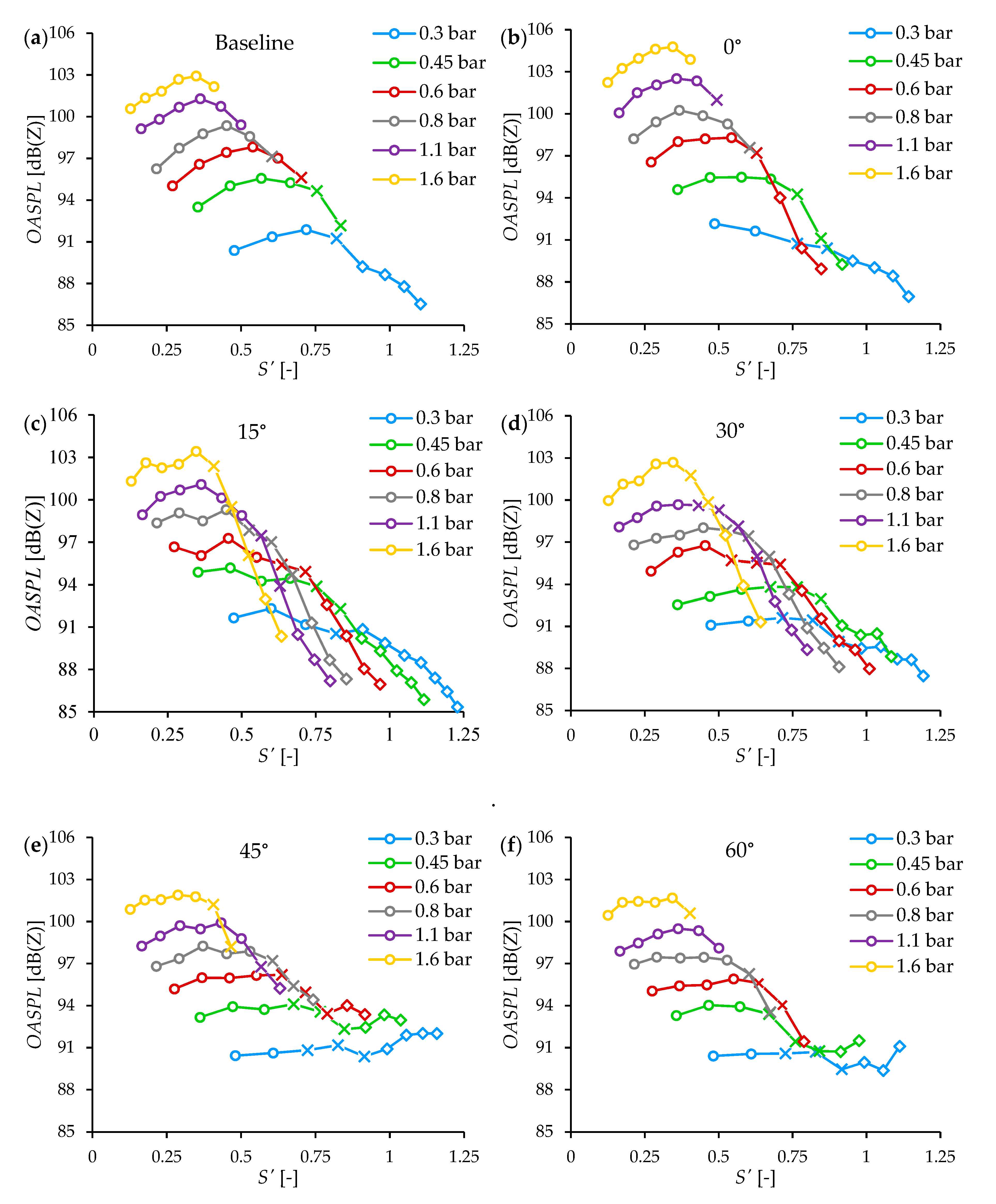
3.2. OASPL at pg = 0.3 bar

Figure 6 shows the variation of the OASPL as a function of S’ and air-to-fuel equivalence ratio, λ, in four different setups: baseline configuration and with 0°, 15°, and 30° quarls equipped. Here, pg was uniformly set to 0.3 bar. The results are presented for both A- and Z-weighting functions, indicating the various flame shapes by using different marker types. The combined expanded uncertainty ranges from 3% to 7.5% for S’ at 95% level of significance, which is 5%–6.5% for λ. The higher values characterize low flow rates, while the lower values are typically close to the blowout. The discussed uncertainty ranges incorporate all cases, including the later discussed ones. Hence, the corresponding error bars are omitted from all figures containing measurement data for better visibility.
As was shown in Figure 4, the dominant frequency band of straight flames is in the regime of the slightly positive gain of the A-weighting function. Therefore, the results are close to the values calculated by Z-weighting. As the flame enters the transitory regime, the OASPL with A-weighting decreases compared to that by Z-weighting since the < 1 kHz regime becomes increasingly dominant. The transitory flame is characterized by a slightly higher OASPL than the straight flame by Z-weighting, which is due to the random alteration between the two stable flame shapes. The noise of the V-shaped flames decreases as the combustion air flow rate increases. This trend is closely linear for all cases and has a higher slope with A-weighting since there is a slight shift towards lower frequencies in the sub-1 kHz frequency regime, in accordance with the swirl combustion literature [6]. The linearity is indicated by the coefficient of determination of 0.9 and above for all cases. Even though the baseline configuration seems to be characterized by the lowest noise emission, the difference is only a few dB at all measurement points in Figure 6a,c. This difference is slightly amplified by the A-weighting function in Figure 6b,d. However, the improved flame stability performance of both 15° and 30° diffusers is remarkable. Overall, the lowest OASPL was measured by using a 15° quarl at λ = 2 or S’ = 1.23. In the following subsection, the effect of quarls is emphasized as a function of S’.

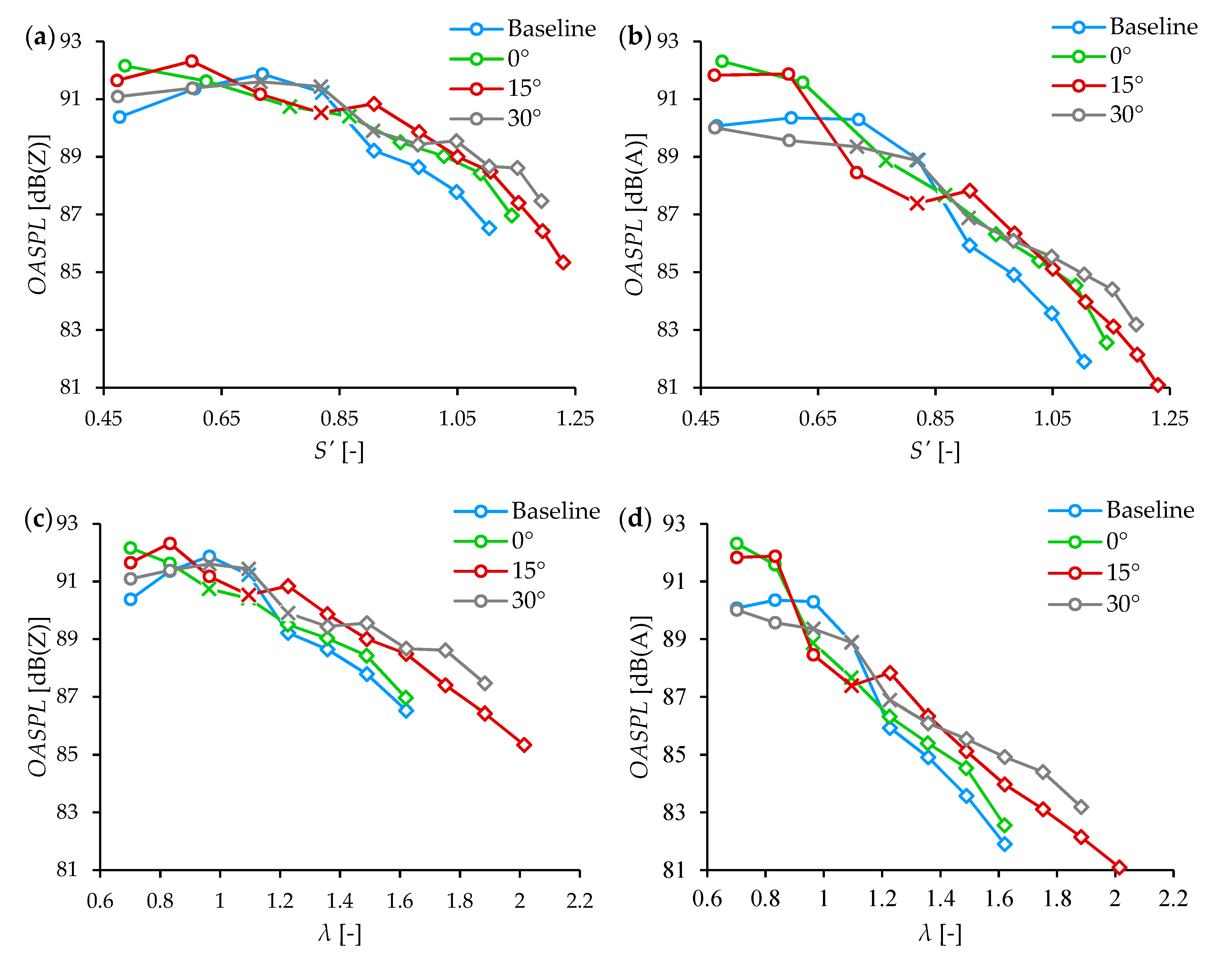
3.3. Effect of Quarls

Besides the emphasized quarls in Section 3.2, 45° and 60° quarls are also discussed in the present subsection. In addition, the analysis covers several additional pgs. Hence, data of various quarls are shown in separate diagrams, evaluating only the OASPL with Z-weighting as a function of S’.
Before proceeding into the results, the fluid dynamical behavior of the quarls is briefly summarized. Compared to the baseline burner, 0° means only a 16 mm longer mixing tube section. In addition, this quarl adds thermal inertia to the system, which facilitates flame stabilization; however, the two configurations practically showed similar results from this point of view. The next two quarls, 15° and 30°, were the best in flame stabilization for the present burner configuration, allowing a significant extension of the stable operating regime at all pg [12]. At the initial combustion air flow rates, the flow was governed by the atomizing air jet at the center; hence, the flow was attached to the quarl wall later. The flow separation here was acceptable since the operation was far from the blowout. As the combustion air flow rate was increased, the increasing S’ resulted in flow attachment to the wall, allowing flame stabilization through the appearing boundary layer. The 45° quarl provided a sufficient flow attachment at lower pg; however, its half cone angle was too large for higher pg where the central regime was notably affected by the atomizing air jet. Therefore, the detached flow resulted in similar flame blowout characteristics as the baseline burner had. The flow was always separated from the 60° quarl; it only provided some protection against cold air entrainment. The blowout characteristics were close to the baseline and 0° configurations.
Figure 7 shows the results of the OASPL measurement of all configurations. While increasing the swirl number at the straight flame shape, combustion noise also increases by few decibels or less. The transitory flame shape is characterized by decreasing noise; however, only V-shaped flames show a clear tendency of decreasing OASPL, which finally might exceed −10 dB compared to the noisiest operation of the given measurement series.
Interestingly, Figure 7e,f show an increasing OASPL when the flame is V-shaped, while the transitory regime indicates a decreasing trend. This property might be attributed to the not well-attached flow to the quarl walls, shown in Figure 8. Stable, V-shaped flame was achieved up to 0.8 and 0.6 bar for the 45° and 60° quarls, respectively. The V-shaped operation was limited to pg = 0.3 bar for the baseline burner configuration and up to 0.6 bar for the 0° quarl. Therefore, further analyses are limited to the mentioned configurations where a stable V-shaped flame was achieved for at least two consequent measurement points, excluding 45° and 60° quarls. Figure 7c,d showed stable V-shaped operation for all pgs, showing a nearly linear decrease in OASPL while increasing S’.
The straight flame is characterized by similar OASPL for all quarls and a given pg. In this state, the higher pg results in higher OASPL. The intersection of the trends is due to the enhanced thrust, generated by the elevated pg, hence, the denominator of Equation (5) was high. Therefore, the increased combustion air flow rate caused a smaller increase in S’ while the OASPL notably decreased in the case of V-shaped flames. As for straight flames, the higher pg leads to higher OASPL for all cases due to the enhanced shear induced by the atomizing jet. The noise under hot conditions was about 20 dB higher due to the following reason. The fuel first mixes with atomizing air; hence, the conditions of ignition could be satisfied here, which lead to a rapid expansion inside the shearing flow structure, significantly enhancing the generated noise by the high-velocity atomizing air jet.
Figure 8 shows four flame images with three different quarls to highlight the flame attachment to the quarl wall, which was mentioned above. Since the burner operates in an open atmosphere, fully attached flames could entrain the least amount of cold ambient air.

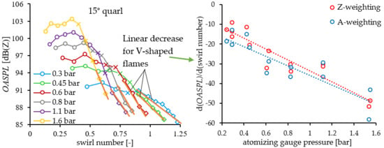
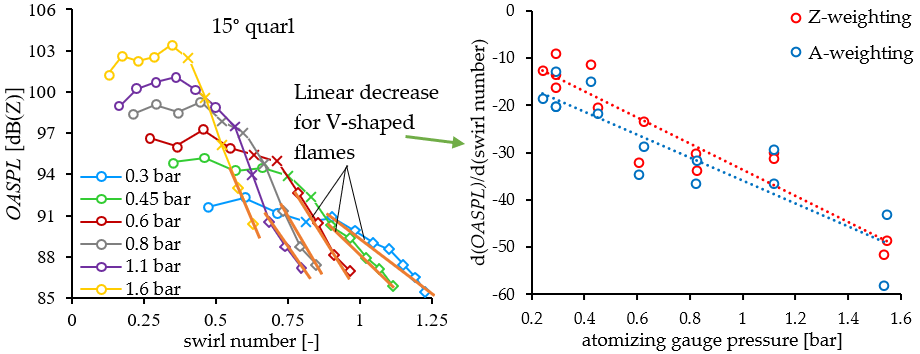
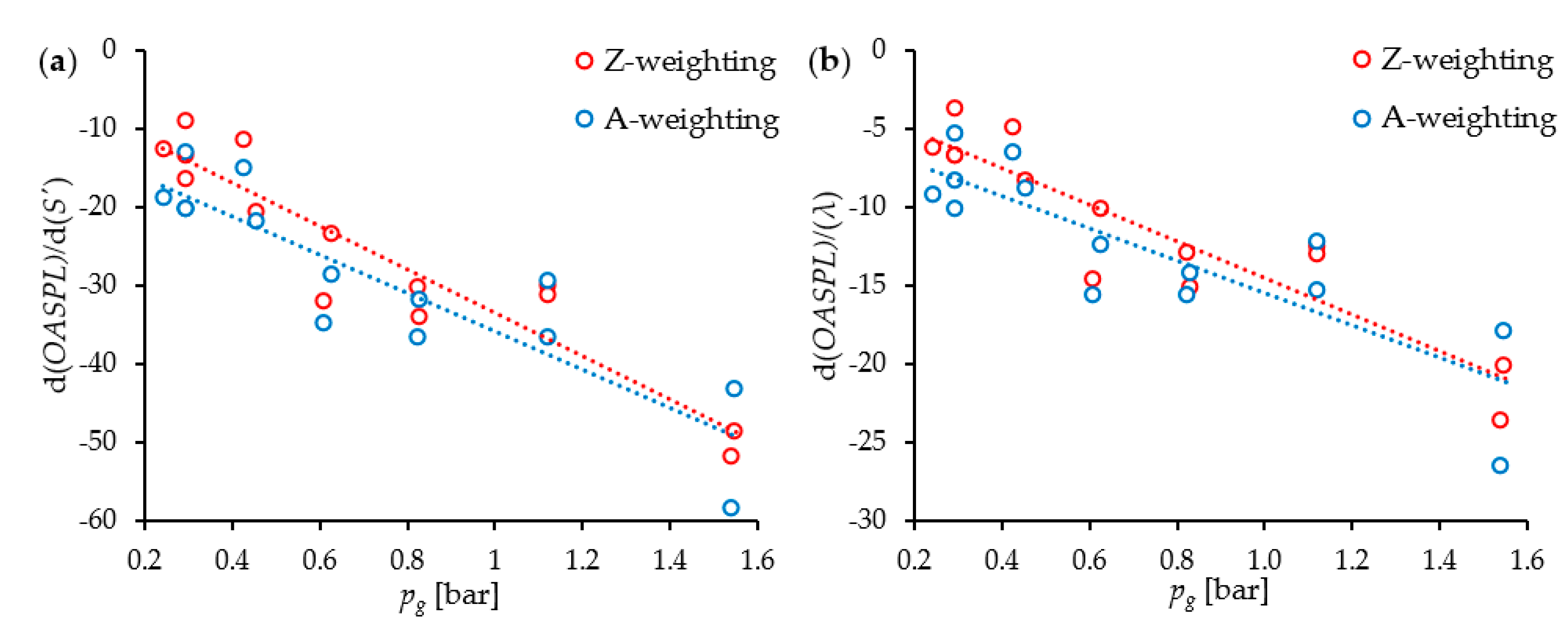
3.4. Linearity Analysis of the OASPL trends of V-shaped Flames

It was shown previously that the quarls provide excellent blowout stability; therefore, several operating points at V-shaped flame were investigated beyond the capabilities of the baseline burner. The extended regime allowed the collection of data, especially at elevated atomizing pressures. The straight flame and transitory regimes both have a relatively low effect on OASPL and showed varying trends. However, the V-shaped flame always showed a close linear decrease in OASPL, which proposes the analysis of linearity.
All the V-shaped operation points were filtered from the above data for the baseline burner and the 0°-30° quarls. Then, the fitting two parameters were determined for all data sets. This procedure was performed by using both A- and Z-weighting functions, analyzing the variation as a function of S’ and air-to-fuel equivalence ratio, λ as well. The resulting coefficient of determinations was listed in Table 3. This procedure required at least two subsequent measurement points, which, hence, may result in a coefficient of determination of unity. Most values well exceed 0.9, except the 30° quarl at pg = 0.45 bar.
The derivative of the fitted lines for both weighting functions was summarized in Figure 9. They follow a closely linear trend as a function of pg. In Figure 9a, the coefficient of determination is 0.878 and 0.796 for Z- and A-weighting functions, respectively. The results as a function of λ, are shown in Figure 9b; the corresponding R2 values are 0,832 and 0,713, respectively. The data scattering at pg = 1.6 bar originated from the following phenomenon. The deviation from the fitted line is attributed to the lower frequency components in the case of the 30° quarl, which is amplified by the A-weighting function, leading to a steeper decreasing trend. However, the 15° quarl featured higher frequencies where the A-weighting function has a positive gain. Nevertheless, the deviation is close to the trend line in the case of Z-weighting. Considering the logarithmic scaling of the OASPL, the discussed result covers a wide range of operating conditions. The use of concluded decreasing derivatives with elevated pg might contribute to advanced combustion chamber designs for decreased noise emission and a healthier environment for the operators and affected personnel.

4. Conclusions

A 15-kW lean premixed prevaporized swirl burner was investigated in the present paper under atmospheric conditions, fueled by standard diesel oil. The noise emission of its operation at various atomizing pressures, swirl numbers, air-to-fuel ratios (λ) were evaluated in terms of sound pressure level. As for geometrical modification, quarls with 0°–60° half cone angles in 15° steps were installed on the burner lip beside the baseline burner. All measurements started from a fixed combustion air flow rate, and it was increased equidistantly until blowout. Straight flame was observed initially in all cases, while the transitory and then the V-shaped flames were limited to a lower number of setups. The overall sound pressure level (OASPL) was evaluated for all setups, using at least a 30 s noise signal at steady operation, using 12 kHz sampling frequency. Based on the results, the following conclusions were derived:
Increasing atomizing pressure results in elevated combustion noise due to the intensifying induced shear. As a consequence, the swirl number decreases as the axial thrust increases.
V-shaped flame of the baseline burner and the 0°–30° quarls showed a linear decrease in OASPL as the swirl number and hence the air-to-fuel ratio increased. The 45° and the 60° quarls resulted in a slightly increasing OASPL at V-shaped flame. However, the flame was not attached to the quarl wall at higher pg.
By fitting a line to the V-shaped operation, OASPL data of the baseline burner and 0°–30° quarls showed a linearly decreasing trend in their derivative by both λ and S’ with the increasing atomizing pressure, by using either A- or Z-weighting functions.

Author Contributions

G.I.N. has evaluated the acoustic data under the supervision of V.J., V.J. conducted the measurements and majority of the paper preparation. The authors contributed equally to the paper. All authors have read and agreed to the published version of the manuscript.

Funding

This paper was supported by the National Research, Development and Innovation Fund of Hungary (NKFIH), projects OTKA-FK 124704 and TUDFO/51757/2019-ITM Thematic Excellence Program, New National Excellence Program of the Ministry of Innovation and Technology (ITM) project №. ÚNKP-19-4-BME-213, and the János Bolyai Research Scholarship of the Hungarian Academy of Sciences (HAS).

Conflicts of Interest

The authors declare no conflict of interest.

Nomenclature

Latin letters
a(m/s)Speed of sound
AFR(–)Air-to-fuel mass flow ratio
B(mm)Height of the swirl slots
D(mm)Diameter of the circular slots
d0(mm)Fuel pipe inner diameter
Gφ(Nm)Axial flux of the angular momentum
Gx(N)Axial thrust
G’x(N)Axial thrust for the geometric swirl number calculation
h(mm)Width of the swirl slots
m ˙ (kg/s)Mass flow rate
Ma(–)Mach number
pg(bar)Atomizing gauge pressure
R(m)Mixing tube inner radius
Re(–)Reynolds number
S(–)Swirl number
S(–)Geometric (estimated) swirl number
s(mm)Slot-to-slot distance in the circumference of the mixing tube
SMD(µm)Sauter Mean Diameter
OASPL(dB)Overall Sound Pressure Level
T(K)Temperature
w(m/s)Velocity
We(–)Weber number
y(piece)Number of circular slots in the cylindrical surface of the mixing tube
z(piece)Number of swirl slots in the cylindrical surface of the mixing tube
Greek letters
α(°)Swirl vane angle
λ(–)Air-to-fuel equivalence ratio
µ(Pa·s)Dynamic viscosity
ψ(–)Blockage factor
ρ(kg/m3)Density
σ(N/m)Surface tension
Subscripts
A Atomizing air
air Sum of air
C Combustion air
F Fuel
S Air passing through the swirl vanes
sto Stoichiometric
x Mixture

References

  1. Liu, Y.; Sun, X.; Sethi, V.; Nalianda, D.; Li, Y.G.; Wang, L. Review of modern low emissions combustion technologies for aero gas turbine engines. Prog. Aerosp. Sci. 2017, 94, 12–45. [Google Scholar] [CrossRef] [Green Version]
  2. Chanphavong, L.; Zainal, Z.A. Characterization and challenge of development of producer gas fuel combustor: A review. J. Energy Inst. 2018. [Google Scholar] [CrossRef]
  3. Lefebvre, A.H.; Ballal, D.R. Gas Turbine Combustion, 3rd ed.; CRC Press: Boca Raton, FL, USA, 2010. [Google Scholar] [CrossRef]
  4. Shen, J.; Li, F.; Li, Z.; Wang, H.; Shen, Y.; Liu, Z. Numerical investigation of air-staged combustion to reduce NOXemissions from biodiesel combustion in industrial furnaces. J. Energy Inst. 2018, 1–13. [Google Scholar] [CrossRef]
  5. Deshmukh, N.N.; Sharma, S.D. Suppression of thermo-acoustic instability using air injection in horizontal Rijke tube. J. Energy Inst. 2017, 90, 485–495. [Google Scholar] [CrossRef]
  6. Huang, Y.; Yang, V. Dynamics and stability of lean-premixed swirl-stabilized combustion. Prog. Energy Combust. Sci. 2009, 35, 293–364. [Google Scholar] [CrossRef]
  7. Noiray, N.; Denisov, A. A method to identify thermoacoustic growth rates in combustion chambers from dynamic pressure time series. Proc. Combust. Inst. 2017, 36, 3843–3850. [Google Scholar] [CrossRef]
  8. Kabiraj, L.; Sujith, R.I. Nonlinear self-excited thermoacoustic oscillations: Intermittency and flame blowout. J. Fluid Mech. 2012, 1–22. [Google Scholar] [CrossRef]
  9. Durox, D.; Moeck, J.P.; Bourgouin, J.F.; Morenton, P.; Viallon, M.; Schuller, T.; Candel, S. Flame dynamics of a variable swirl number system and instability control. Combust. Flame 2013, 160, 1729–1742. [Google Scholar] [CrossRef]
  10. Ballester, J.; García-Armingol, T. Diagnostic techniques for the monitoring and control of practical flames. Prog. Energy Combust. Sci. 2010, 36, 375–411. [Google Scholar] [CrossRef]
  11. Shen, Y.; Li, F.; Liu, Z.; Wang, H.; Shen, J. Study on the characteristics of evaporation–atomization–combustion of biodiesel. J. Energy Inst. 2018, 92, 1458–1467. [Google Scholar] [CrossRef]
  12. Józsa, V.; Kun-Balog, A. Effect of quarls on the blowout stability and emission of pollutants of a liquid-fueled swirl burner. J. Eng. Gas Turbines Power 2018. [Google Scholar] [CrossRef]
  13. Rodríguez-Díaz, A.; Adenso-Díaz, B.; González-Torre, P.L. A review of the impact of noise restrictions at airports. Transp. Res. Part D Transp. Environ. 2017, 50, 144–153. [Google Scholar] [CrossRef] [Green Version]
  14. International Civil Aviation Organization. Guidance on the Balanced Approach to Aircraft Noise Management; International Civil Aviation Organization: Montreal, QC, Canada, 2008. [Google Scholar] [CrossRef]
  15. Ganic, E.M.; Netjasov, F.; Babic, O. Analysis of noise abatement measures on European airports. Appl. Acoust. 2015, 92, 115–123. [Google Scholar] [CrossRef]
  16. Laurenzo, R. Hushing the roar. Aerosp. Am. 2006, 44, 38–42. [Google Scholar]
  17. Smith, T.J.B.; KIlham, J.K. Noise Generation by Open Turbulent Flames. J. Acoust. Soc. Am. 1963, 35, 715–724. [Google Scholar] [CrossRef]
  18. Rolls-Royce. The Jet Engine, 5th ed.; Wiley-Blackwell: Hoboken, NJ, USA, 2015. [Google Scholar]
  19. Férand, M.; Livebardon, T.; Moreau, S.; Sanjosé, M. Numerical Prediction of Far-Field Combustion Noise from Aeronautical Engines. Acoustics 2019, 1, 12. [Google Scholar] [CrossRef] [Green Version]
  20. Geyer, T.F.; Sarradj, E. Self Noise Reduction and Aerodynamics of Airfoils With Porous Trailing Edges. Acoustics 2019, 1, 22. [Google Scholar] [CrossRef] [Green Version]
  21. Moreau, S. Turbomachinery Noise Predictions: Present and Future. Acoustics 2019, 1, 8. [Google Scholar] [CrossRef] [Green Version]
  22. Clavin, P.; Siggia, E.D. Turbulent Premixed Flames and Sound Generation. Combust. Sci. Technol. 1991, 78, 147–155. [Google Scholar] [CrossRef]
  23. IEC 61672. International Standard for Sound Level Meters (Electroacoustics); IEC: Geneva, Switzerland, 2013. [Google Scholar]
  24. Everest, F.A. Master Handbook of Acoustics, 4th ed.; McGraw-Hill: New York, NY, USA, 2001. [Google Scholar] [CrossRef]
  25. Noise Control Act, Public Law 92-574, 27 October 1972; 86 Stat. 1234; 42 USC; Federal Government of the United States: Washington, DC, USA, 1972.
  26. Canada Labour Code, Part II; R.S.C. 1985, c. L-2; Parliament of Canada: Ottawa, ON, Canada, 1985.
  27. Ministry of the Environment, Government of Japan. Law No. 98 of 1968; Amended by Law No. 91 of 2000; Ministry of the Environment, Government of Japan: Tokyo, Japan, 2000.
  28. EN. Directive 2003/10/EC of the European Parliament and of the Council. Off. J. Eur. Union 2003, 42, 38–44. [Google Scholar]
  29. Freund, J.B. Noise sources in a low-Reynolds-number turbulent jet at Mach 0.9. J. Fluid Mech. 2001, 438, 277–305. [Google Scholar] [CrossRef]
  30. Bailly, C.; Lafon, P.; Candel, S. Subsonic and supersonic jet noise predictions from statistical source models. AIAA J. 1997, 35, 1688–1696. [Google Scholar] [CrossRef]
  31. Candel, S.; Durox, D.; Ducruix, S.; Birbaud, A.-L.; Noiray, N.; Schuller, T. Flame Dynamics and Combustion Noise: Progress and Challenges. Int. J. Aeroacoustics 2009, 8, 1–56. [Google Scholar] [CrossRef]
  32. Swaminathan, N.; Balachandran, R.; Xu, G.; Dowling, A.P. On the correlation of heat release rate in turbulent premixed flames. Proc. Combust. Inst. 2011, 33, 1533–1541. [Google Scholar] [CrossRef]
  33. Pillai, A.L.; Kurose, R. Numerical investigation of combustion noise in an open turbulent spray flame. Appl. Acoust. 2018, 133, 16–27. [Google Scholar] [CrossRef]
  34. Speth, R.L.; Ghoniem, A.F. Using a strained flame model to collapse dynamic mode data in a swirl-stabilized syngas combustor. Proc. Combust. Inst. 2009, 32, 2993–3000. [Google Scholar] [CrossRef]
  35. Singh, K.K.; Zhang, C.; Gore, J.P.; Mongeau, L.; Frankel, S.H. An experimental study of partially premixed flame sound. Proc. Combust. Inst. 2005, 30, 1707–1716. [Google Scholar] [CrossRef]
  36. Kilham, J.K.; Kirmani, N. The effect of turbulence on premixed flame noise. Symp. Combust. 1979, 17, 327–336. [Google Scholar] [CrossRef]
  37. Balakrishnan, P.; Srinivasan, K. Influence of swirl number on jet noise reduction using flat vane swirlers. Aerosp. Sci. Technol. 2018, 73, 256–268. [Google Scholar] [CrossRef]
  38. Balakrishnan, P.; Srinivasan, K. Jet noise reduction using co-axial swirl flow with curved vanes. Appl. Acoust. 2017, 126, 149–161. [Google Scholar] [CrossRef]
  39. Shanbhogue, S.J.; Sanusi, Y.S.; Taamallah, S.; Habib, M.A.; Mokheimer, E.M.A. Flame macrostructures, combustion instability and extinction strain. Combust. Flame 2015, 1–14. [Google Scholar] [CrossRef]
  40. Hong, S.; Shanbhogue, S.J.; Ghoniem, A.F. Impact of fuel composition on the recirculation zone structure and its role in lean premixed flame anchoring. Proc. Combust. Inst. 2015, 35, 1493–1500. [Google Scholar] [CrossRef] [Green Version]
  41. Choi, B.C.; Ghoniem, A.F. Stabilization and blowout characteristics of lean premixed turbulent flames behind a backward-facing step in a rectangular combustor with heated propane-air mixtures. Fuel 2018, 222, 627–637. [Google Scholar] [CrossRef]
  42. Lefebvre, A.H.; Miller, D. The Development of an Air Blast Atomizer for Gas Turbine Application; CoA. Report Aero No. 193; College of Aeronautics Cranfield: Cranfield, UK, 1966. [Google Scholar]
  43. Csemány, D.; Józsa, V. Fuel Evaporation in an Atmospheric Premixed Burner: Sensitivity Analysis and Spray Vaporization. Processes 2017, 5, 80. [Google Scholar] [CrossRef] [Green Version]
  44. Singh, A.V.; Yu, M.; Gupta, A.K.; Bryden, K.M. Investigation of noise radiation from a swirl stabilized diffusion flame with an array of microphones. Appl. Energy 2013, 112, 313–324. [Google Scholar] [CrossRef]
  45. Hadef, R.; Merkle, K.; Lenze, B.; Leuckel, W. An experimental study of airblast atomizer spray flames. J. Inst. Energy 2000, 73, 50–55. [Google Scholar]
  46. Lefebvre, A.H.; McDonell, V.G.; Arthur, H.; Lefebvre, V.G.M. Atomization and Sprays, 2nd ed.; CRC Press: Boca Raton, FL, USA, 2017. [Google Scholar]
  47. Lefebvre, A.H.; Arthur, H. Lefebvre. Airblast atomization. Prog. Energy Combust. Sci. 1980, 6, 233–261. [Google Scholar] [CrossRef]
  48. Urbán, A.; Zaremba, M.; Malý, M.; Józsa, V.; Jedelský, J. Droplet dynamics and size characterization of high-velocity airblast atomization. Int. J. Multiph. Flow. 2017, 95, 1–11. [Google Scholar] [CrossRef] [Green Version]
  49. Beér, J.M.; Chigier, N.A. Combustion Aerodynamics; Robert, E., Ed.; Krieger Publishing Company, Inc.: London, UK, 1972. [Google Scholar]
  50. Galley, D.; Ducruix, S.; Lacas, F.; Veynante, D. Mixing and stabilization study of a partially premixed swirling flame using laser induced fluorescence. Combust. Flame 2011, 158, 155–171. [Google Scholar] [CrossRef]
  51. Singh, A.V.; Yu, M.; Gupta, A.K.; Bryden, K.M. Thermo-acoustic behavior of a swirl stabilized diffusion flame with heterogeneous sensors. Appl. Energy 2013, 106, 1–16. [Google Scholar] [CrossRef]
Figure 1. The test rig.
Acoustics 02 00010 g001
Figure 2. Cross-section of the burner and the quarl.
Acoustics 02 00010 g002
Figure 3. Straight flame at the end of the transitory regime (left, pg = 0.3 bar, λ = 1.1, and S’ = 0.82), stable V-shaped flame (middle, pg = 0.3 bar, λ = 1.23, and S’ = 0.91), and V-shaped flame with a 45° quarl (right, pg = 0.3 bar, λ = 1.25, and S’ = 0.92).
Acoustics 02 00010 g003
Figure 4. Spectrogram of a single measurement at pg = 0.8 bar, using a 15° quarl. The shaded areas indicate the changeover between two points with distinct flame characteristics. Blowout is indicated by the vertical black line, beyond which the spectrum of the cold flow noise is visible.
Acoustics 02 00010 g004
Figure 5. A and Z weighting functions.
Acoustics 02 00010 g005
Figure 6. (a,c) OASPL with Z- and (b,d) A-weighting functions using the baseline burner and various quarls as a function of S’ (a,b) and λ (c,d) all at pg = 0.3 bar. Symbols: straight flame (○), transitory flame (×), and V-shaped flame (◊).
Acoustics 02 00010 g006
Figure 7. OASPL of the (a) baseline burner and (bf) 0°–60° quarls at six pgs as a function of S’, using Z-weighting. Symbols: straight flame (○), transitory state (×), and V-shaped flame (◊).
Acoustics 02 00010 g007
Figure 8. Flame images with various quarls. (a) 15° (b) 30° qualrs, showing attached flame to its wall. (c) 45° with detached flame in V-shaped mode and (d) straight flame also detached from the quarl wall.
Acoustics 02 00010 g008
Figure 9. The derivative of the fitted linear trend lines as a function of the atomizing pressure. (a) geometric swirl number, (b) air-to-fuel equivalence ratio.
Acoustics 02 00010 g009
Table 1. Estimated characteristics of atomization at various pg.
pg (bar)SMD (µm)WeA (–)AFR (–)ρA (kg/m3)TA (K)Ma (–)
0.321.67790.7781.272770.62
0.4516.211210.9481.312680.75
0.613.414381.0891.342610.85
0.811.118301.2491.392520.95
1.19.1723631.4511.452411.08
1.67.4431431.7251.542271.25
Table 2. Fuel properties at 25 °C.
PropertyValue
Thermal power15 kW
Lower heating value43 MJ/kg
Fuel flow rate0.35 g/s
Dynamic viscosity3.45 mPa·s
Density830 kg/m3
Surface tension28 mN/m
Table 3. The coefficient of determination of linear fit lines for A- and Z-weighting functions as a function of S’ and λ.
Quarlpg (bar)R2 (S’, dB(Z))R2 (S’, dB(A))R2 (λ, (dBZ))R2 (λ, (dBA))
Baseline0.30.9440.9700.9710.988
0.30.8850.9240.9260.955
15°0.30.9630.9960.9930.993
0.450.9890.9970.9950.987
0.60.9880.9650.9790.947
0.80.9740.9640.9660.955
1.10.9990.9990.9980.998
1.51.0001.0001.0001.000
30°0.30.8020.9340.8530.967
0.450.7630.7220.7930.739
0.60.9830.9800.9700.966
0.80.9870.9940.9780.989
1.10.9930.9980.9890.995
1.50.9940.9900.9920.987

