Article

Chemical Equilibrium Fracture Mechanics—Hydrogen-Induced Crack Growth Initiation

by
Andreas G. Varias
Euro Harmonization and Engineering, Makedonias 17, N. Iraklio 14121, Greece
Corros. Mater. Degrad. 2026, 7(1), 20; https://doi.org/10.3390/cmd7010020
Submission received: 25 January 2026 / Revised: 4 March 2026 / Accepted: 12 March 2026 / Published: 17 March 2026
(This article belongs to the Special Issue Hydrogen Embrittlement of Modern Alloys in Advanced Applications)

Abstract

Hydrogen-induced crack growth initiation, in metallic structures, is studied under constant temperature and chemical equilibrium, by employing Chemical Equilibrium Fracture Mechanics (CEFM). The conditions of small-scale, contained and large-scale hydrogen embrittlement are introduced and the areas of material deterioration, together with the distributions of stress and hydrogen concentration, including hydride volume fraction, are derived analytically. It is shown that the shape of the material deterioration zone is identical for embrittlement caused either by hydrogen in solid solution or by hydride precipitation; the size depends on the strength of the asymptotic crack-tip field, which develops by the mechanical loading in the hydrogen-free structure, as well as on the average hydrogen content absorbed by the structure. It is also shown that a linear relation exists between a power of the threshold of crack-growth initiation and the logarithm of hydrogen content, depending on the extent of hydrogen embrittlement and material elastic-plastic deformation. These linearity trends, which are derived by the present analysis, are confirmed by published experimental fracture mechanics measurements on several non-hydride- and hydride-forming alloys, including α/β hydride-forming alloys. The present study promotes structural integrity assessments, without reliance on complicated coupled numerical analysis of material deformation, hydrogen diffusion and hydride precipitation.

1. Introduction

Hydrogen technology and its use are expected to develop significantly, in order to provide means of mitigating climate change due to anthropogenic greenhouse gas emissions. Hydrogen, produced from renewable energy sources, is seen as an alternative fuel or fuel-carrier both in energy generation and transport. It is expected to be generated in areas around the globe, where there is an abundance of solar and wind energy, and subsequently transported to places where the consumption is highest. Thus, a global energy transition is foreseen, based on hydrogen [1,2,3,4,5].
A key issue in the development of hydrogen economy is safety/structural integrity. Extensive use of hydrogen technology/applications will be necessarily accompanied by developments on structural integrity assessments, due to new designs, but also due to the significant increase in the use of existing or moderately modified designs; the last need to be examined, simply due to the relation of failure probability with the number of devices/equipment and operation time.
A basis of structural integrity assessments is provided by Linear Elastic or Elastic-Plastic Fracture Mechanics (LEFM, EPFM). The assessment is founded on the principle of similitude (e.g., [6]). When this principle is satisfied, the stress and strain distributions are similar both in the structure under evaluation and a specimen loaded in the lab. These distributions are characterized either by the stress intensity factor, in the case of LEFM, or J-integral, in the case of EPFM (e.g., [7,8,9]); to be precise, the distributions are identical if properly non-dimensionalized. Both the stress intensity factor and J-integral are related to the energy, which is available for material deterioration and fracture. Consequently, based on the principle of similitude, fracture/crack growth occurs under the same value of the stress intensity factor or J-integral in the structure and the lab specimen, which are made of the same material, including microstructure. Then, fracture measurements (i.e., of critical stress intensity factor or J-integral) in the lab can be used to assess the integrity and predict crack growth in the structure under evaluation. This basis needs to be extended in order to take into account material deterioration and crack-tip field modifications, caused by hydrogen.
It is well-known that hydrogen, when absorbed during operation or introduced during manufacturing, diffuses easily in metallic structures due to its size, and may lead to embrittlement, which can cause failure under lower loads, compared to those sustained by a hydrogen-free material. Several hydrogen embrittlement mechanisms have been proposed (e.g., [10,11]). An initial material categorization is related to the precipitation or not of hydrides.
Hydrides precipitate in alloys, based on titanium, zirconium, magnesium, vanadium and niobium. Hydrides are brittle and therefore their precipitation, when hydrogen terminal solid solubility is exceeded, causes material degradation, which leads to fracture, if sufficient mechanical loading is applied. Therefore, the underlying embrittlement mechanism is understood. One additional reason for considering the category of hydride-forming alloys is the significant modification of the crack-tip field, due to the expansion of the hydrides, during precipitation [12,13,14]. The modified crack-tip field is characterized by a constant stress trace in the hydride precipitation zone, under constant temperature and hydrogen chemical equilibrium.
In the case of hydrogen embrittlement without the formation of hydrides, such as steel, nickel-based and β-phase titanium alloys, there are several proposed mechanisms such as hydrogen-enhanced decohesion (HEDE), hydrogen-enhanced localized plasticity (HELP), and adsorption-induced localized slip and combinations. Consequently, there is currently a lack of consensus in the scientific community on a particular mechanism for hydrogen embrittlement in non-hydride-forming metallic materials. In addition, hydrogen, being in solid solution, does not produce any significant effect on crack-tip stress field. More information is given in review papers [10,11,15] as well as in a recent publication of the author [16].
For all embrittlement cases, various fracture models have been developed, which are based on the hypothesis of a failure process (e.g., [17,18]). Therefore, their applicability and validity depend on the operation or not of the assumed failure process.
The objective of the present work is the extension of integrity assessment methodology, based on the principle of similitude, when a structure is used/operates in the presence of hydrogen. In this extension, the features of the crack-tip fields in a hydrogen environment, including their modifications, when hydride precipitation occurs need to be rigorously taken into account. This extension shall not rely on the details of a fracture mechanism, the implications of which are expected to be incorporated in the values of crack-growth threshold or fracture toughness, measured with standard fracture tests. Therefore, detailed information on how hydrides (single, in clusters or networks) or the accumulation of hydrogen in interstitial sites and traps affect material integrity will not be used. However, the result/outcome/effect of any of these fracture mechanisms on the intensity of the crack-tip field at growth initiation is an important ingredient of the extended methodology.
The vehicle for the extension of the integrity assessment methodology is Chemical Equilibrium Fracture Mechanics (CEFM), a multidisciplinary approach of thermodynamics, materials science, solid mechanics and mathematics, which is based on the assumption of material deterioration under chemical equilibrium [12,13,14,16,19]. In the case of hydrogen embrittlement, material deterioration is examined following hydrogen redistribution, which leads to hydrogen concentration spatial distribution independent of time. In industrial applications this assumption corresponds to steady-state facility operation, which provides the basic conditions of initial design related to material selection and main dimensions, given the range of operation parameters. Indeed, according to ASME B31.12 [20], on hydrogen piping and pipelines, and ASME BPVC.VIII.3 [21], on hydrogen pressure vessels, the threshold stress intensity factor of crack growth initiation in a hydrogen atmosphere is used in the design of these facilities. It is emphasized that hydrogen-induced crack growth initiation near the threshold occurs under conditions approaching chemical equilibrium (e.g., [22]). Under CEFM, the coupling of the operating mechanisms of material deformation, hydrogen diffusion and hydride precipitation, is taken into account. It is worth mentioning that the structure of crack-tip fields, derived based on CEFM, is clearly presented via analytic relations. Thus, the work of extending structural integrity assessment methodology is significantly facilitated, without compromising on accuracy.
It is emphasized that CEFM does not apply when mechanical load and thermal transients are of interest, during which the time evolution of mechanisms, such as hydrogen absorption/desorption, diffusion, and hydride precipitation/dissolution, becomes important. In the case of constant mechanical and thermal loads, CEFM provides predictions at the limit of chemical equilibrium.
In the following Section 2, the conditions of small-scale, contained and large-scale hydrogen embrittlement are introduced. These conditions are used in a similar way to small-scale and large-scale yielding in LEFM and EPFM. Under each one of these conditions, the areas of hydrogen-induced material deterioration are derived, under both hydrogen in solid solution and hydride precipitation based on CEFM. In Section 3, simple fracture criteria, which do not rely on the details of the operating mechanisms, are used to derive thresholds and their dependence on average hydrogen content. Subsequently, these predictions are compared with fracture test measurements published in the literature. The comparisons are performed for several non-hydride- and hydride-forming alloys, including two-phase Ti-alloys. Subsequently, the main/most important points of an integrity assessment are given for a structure exposed to hydrogen, in the cases of small-scale yielding and large-scale yielding/HRR-dominance under mechanical loading alone, (i.e., before the absorption of hydrogen).

2. Materials and Methods

In LEFM and EPFM, structural integrity assessments are performed by using the principle of similitude. According to this principle, the crack-tip field in the structure under investigation and in a lab-specimen, made of the same material, need to be similar. If the validity of the principle of similitude is confirmed, the measurements of crack growth initiation in the lab-specimen can be used to predict crack growth initiation in the structure.
Under small-scale yielding, both in the lab-specimen and the structure, the plastic zone size is small compared to the characteristic length of the geometry. Then, in the lab-specimen and the structure, there is an annulus surrounding the crack-tip, where K-field dominates [23]. Taking into account that the stress intensity factor of the K-field is related to the energy which is available in the material for damage and crack growth initiation, it is concluded that, under the conditions of similitude and small-scale yielding, crack growth initiation occurs when the stress intensity factor reaches the same critical value in the lab-specimen and the structure. Then by measuring the critical stress intensity factor in the lab, one predicts the critical load at which crack growth initiation occurs in the structure.
Similarly, under large-scale yielding, both in the lab-specimen and the structure, the plastic zone is comparable to the characteristic length of the geometry. Then, considering validity of similitude in the lab specimen and the structure, there is an annulus surrounding the crack-tip where HRR-field dominates [24,25]. Taking into account that the intensity of the HRR-field, given by J-integral [26], is related to the energy which is available in the material for damage and crack growth initiation, it is concluded that, under the conditions of similitude and large-scale yielding, crack growth initiation occurs when J-integral reaches the same critical value in the lab-specimen and the structure. Then by measuring the critical value of J-integral in the lab, one predicts the critical load at which crack growth initiation occurs in the structure.
In order to apply a similar structural integrity methodology, when hydrogen embrittlement occurs in a metallic structure, the principle of similitude needs to be considered. Then, in addition to the conditions of small- or large-scale yielding, the conditions of small-scale, contained or large-scale hydrogen embrittlement need to be introduced and taken into account.
In the following, a structure with a crack is considered. A Cartesian coordinate system, ( x 1 ,   x 2 ,   x 3 ) , is specified, which has origin at the crack tip. x 1 lies on the crack plane, normal to the crack edge. x 2 is normal to the crack plane. Also ( r , φ ,   x 3 ) is the respective cylindrical coordinate system, where r is the radial distance from the crack tip and φ is the angle measured from the crack plane. In the present discussion, the structure is assumed to be subjected to the conditions of hydrogen chemical equilibrium and constant temperature, T , under the most important/detrimental plane strain mode I loading. All following relations are written with respect to the previously mentioned Cartesian coordinate system, and repetition of indices denotes summation. Temperature is specified in Kelvin. Also, all quantities are specified in the metric system. Additional unit information is also given, if required, when a quantity appears for the first time in the text. All symbols used in the present analysis and respective definitions are presented in Table 1.
The analysis is based on CEFM, which has been presented in detail in previous studies [12,13,14,16,19]. Elements of CEFM are given in the following, to the extent which is necessary for understanding the conditions of small-scale, contained and large-scale hydrogen embrittlement. For additional information and in order to have a complete view of CEFM, the introduced ideas and their importance/implications, the interested reader is encouraged to consult the previously mentioned publications.
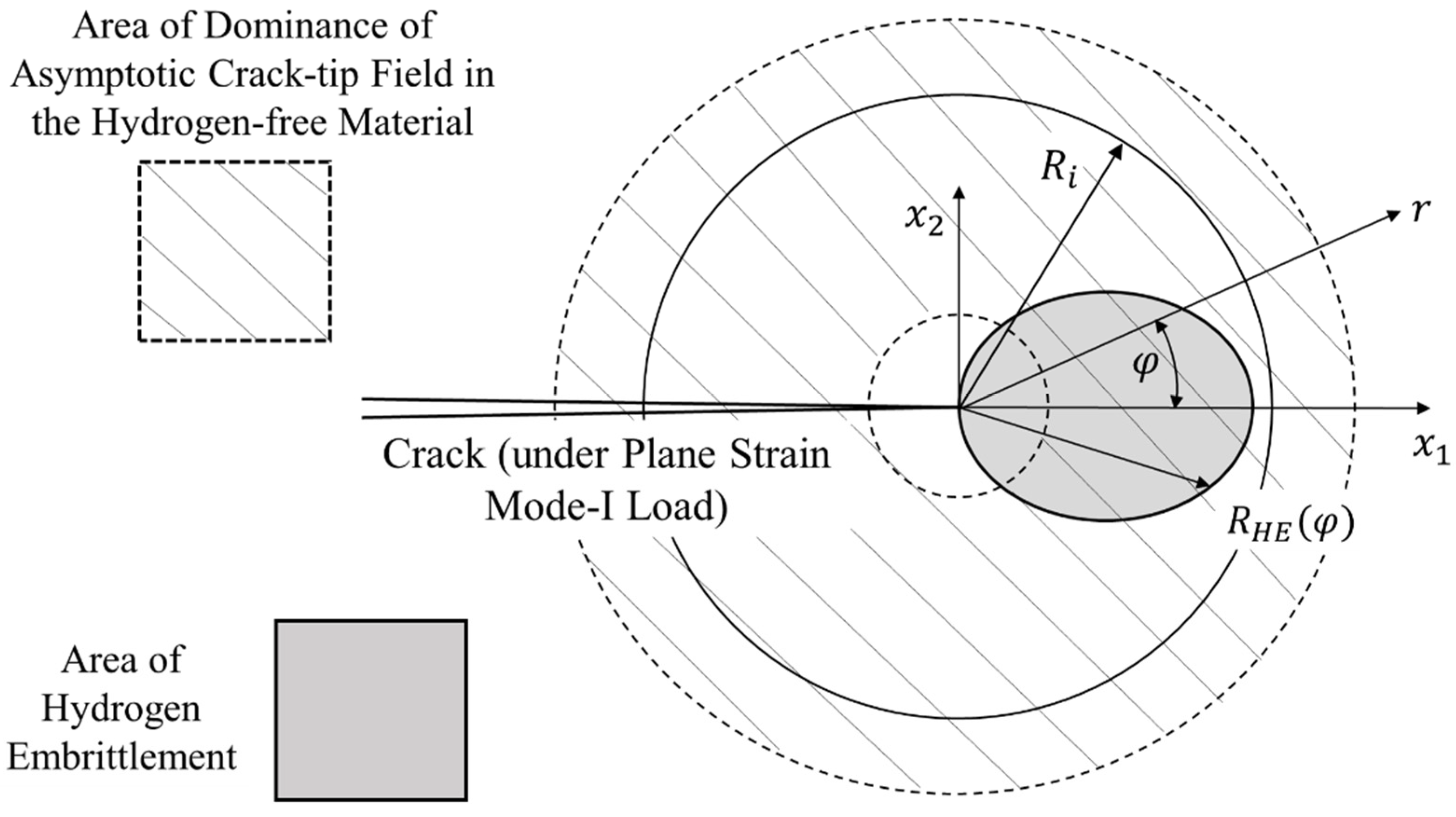
In order to enhance the understanding of the following sections, a graphic illustration of the introduced concepts of small-scale and contained hydrogen embrittlement is given in Figure 1, together with the coordinate system, which is used in the analysis.

2.1. Small-Scale Hydrogen Embrittlement

Small-scale hydrogen embrittlement is defined as the condition under which the deteriorated area ahead of the crack lies within an annulus of K-field dominance. If R H E , R i and L are the size of hydrogen embrittlement area, the inner radius of the K-field dominance annulus and the characteristic length of the structure, then, under small-scale hydrogen embrittlement, the following relation is valid:
R H E < R i < L .
The characteristic length, L , is the smallest length of the structure which is related to the stress intensity factor of K-field (e.g., crack length, crack ligament or other length, related to the geometry of the structure, near the existing crack). In the case of plane strain mode-I loading, the stress intensity factor, K I , is proportional to an applied stress measure, σ , and the square-root of L , ( K I σ L ) .
In the hydrogen embrittlement area, the material has lost toughness due to the presence of hydrogen. In non-hydride-forming alloys, such as steel and nickel-based alloys, or in hydride-forming alloys, such as β-Ti, where embrittlement may occur before the precipitation of hydrides, hydrogen, in the embrittlement area, is in solid solution at a concentration level sufficient to reduce ductility. Hydrogen in reversible traps, such as dislocations, is also expected to contribute to hydrogen embrittlement. Then, in Relation (1), the size of the hydrogen embrittlement area is defined by the boundary at which hydrogen both in interstitial lattice sites and reversible traps reaches a critical level:
R H E = r | C H + C T = C cr H + T ,
where C H and C T are the concentrations of hydrogen in solid solution in interstitial lattice sites and reversible traps, respectively. C c r H + T could be measured by performing standard tensile tests either in a hydrogen atmosphere or of specimens with hydrogen content, introduced before the performance of the testing; care should be taken, with respect to hydrogen pressure or specimen hydrogen content, so that specimen ductility during tensile testing reaches a minimum. Fracture tests are also a source for specifying C c r H + T .
Taking into account that hydrogen in interstitial lattice sites and reversible traps does not modify the crack-tip stress field significantly, one may conclude that, under small-scale hydrogen embrittlement, R H E may reach the size of the inner radius of K-field dominance annulus, R i . Therefore, when no hydrides are present, Relation (1) is rewritten as follows:
R H E R i < L .
In hydride-forming alloys, if embrittlement occurs due to the precipitation of brittle hydrides, such as α-Zr or α-Ti, the hydrogen embrittlement area is the hydride precipitation zone. If r h z is the size of the hydride precipitation zone, then:
R H E = r h z .
Due to the expansion of the precipitating hydrides, the stress field is significantly modified. Therefore, in hydride-forming alloys under small-scale hydrogen embrittlement, the size of the area of material deterioration is always smaller than the inner radius of the annulus of K-field dominance: R H E = r h z < R i < L .
In the case of two-phase hydride-forming alloys, such as α/β-Ti and α/β-Zr, hydrogen embrittlement in α-phase is caused by hydride precipitation, while in β-phase, which has significantly higher hydrogen solubility, the embrittlement occurs before the precipitation of hydrides. Then, in this case, there are two lengths related to hydrogen embrittlement, one for each phase:
R H E , α = r h z , α ,
R H E , β = r | C β H + C β T = C cr , β H + T   .
Then in α/β hydride-forming alloys, small-scale hydrogen embrittlement occurs, when the following relations are both satisfied:
r h z , α < R i < L ,
R H E , β R i < L .
Under crack-growth initiation caused by hydride precipitation, r h z , α > R H E , β . The treatment of two-phase hydride-forming alloys is discussed in [19]. Based on this treatment, the hydrogen embrittlement zone contains both phases.
It is worth mentioning that in ductile alloys, the existence of an annulus of K-field dominance implies that small-scale yielding conditions are also satisfied. Therefore, the size of the plastic zone, r p , shall be smaller than the inner radius of the K-field dominance annulus: r p < R i < L .
In the analysis of structural integrity, under small-scale hydrogen embrittlement, relations (1) or (3), or (7) and (8), depending on the alloy, need to be confirmed. Therefore, besides R i , derived by well-known elastic-plastic analysis, R H E has to also be evaluated; it is noted that R i is defined in a way that the hydrogen embrittled area is excluded, as shown in Figure 1 and Relation (1). In the following, R H E is derived, by considering CEFM, which is applicable at crack growth initiation, under hydrogen chemical equilibrium.
It is assumed that S i j is the stress due to applied mechanical loading, when no hydrogen is present in the structure. When there is no hydride precipitation, the stress field is only negligibly affected by the presence of hydrogen in solid solution e.g., [12,16]. Then the stress field of the embrittled structure, σ i j , is about equal to that before the absorption, dissolution and distribution of hydrogen:
σ i j S i j .
Under hydrogen chemical equilibrium and constant temperature, the distribution of hydrogen in solid solution in interstitial lattice sites, in the body of the structure, satisfies the following well-known relation:
C H C R e H = e x p [ ( σ k k σ R e ) 3 R T V ¯ H ] .
R is the gas constant (=8,314 J mole−1 K−1). V ¯ H is the molal volume of hydrogen in solid solution. According to (10), the distribution of hydrogen in solid solution, in interstitial lattice sites, is related to the stress trace and hydrogen concentration of a reference particle, ( σ R e ,   C R e H ) . In order to simplify the analysis, the reference particle is selected to be far away from the crack edge and faces. Then, σ R e is generally negligible compared to the near-tip stresses and, consequently, compared to σ k k in Relation (10). Furthermore, when the structure is subjected to hydrogen pressure, the reference particle is selected on the surface, which is exposed to hydrogen gas. Consequently, C R e H satisfies Sievert’s law and therefore it is proportional to the square root of hydrogen pressure, p , or in the case of deviation from perfect gas constitutive relation, as expected at high hydrogen pressures, C R e H is proportional to the square root of hydrogen fugacity, F .
Furthermore, by considering chemical equilibrium between hydrogen in interstitial lattice sites and reversible traps, C T is derived [27], based on Fermi–Dirac statistics (e.g., [28]):
C T C H = K e q N T ( K e q 1 ) C H + N I ,
where:
K e q = 1 θ I θ I θ T 1 θ T = exp ( Δ E T R T ) ,
C H = θ I N I ,
C T = θ T N T .
K e q is the chemical equilibrium constant of hydrogen in interstitial and trap sites, which depends, exponentially, on trap binding energy, Δ E T . N I is the number of interstitial sites per unit volume, divided by Avogadro’s number, N A (=6,022 × 1023 atoms per mol), and θ I is the fraction of occupied interstitial sites. N T is the number of trap sites per unit volume (which includes the possibility of several hydrogen atoms trapped at a site), divided by Avogadro’s number, and θ T is the fraction of occupied trap sites. In the above relations, C H and C T are given in moles per unit volume. It is noted that, according to Relation (11), when the occupancy of interstitial lattice sites is small ( θ I 1 ) , also satisfying ( K e q 1 ) θ I 1 , the total hydrogen concentration in interstitial lattice sites and traps is proportional to hydrogen concentration in interstitial lattice sites: C H + C T = ( K e q N T / N I + 1 ) C H . The same result is derived if both occupancies of interstitial sites and traps are small (e.g., [29]). Under the condition of small-scale hydrogen embrittlement, crack-tip plastic dissipation does not contribute to the number of trap sites at the boundary of the hydrogen embrittlement zone. The number of trap sites could be assumed to be constant, e.g., due to grain boundaries or dislocations introduced during manufacturing.
In the case of α/β alloys, relations similar to (10)–(14) are valid for each one of the two phases [19].
Relation (10) is valid at the boundary of the hydrogen embrittlement zone, at which C H + C T ( C H ) = C c r H + T . It is noted that C H | C c r H + T = C c r H + T C T ( C H | C c r H + T ) and therefore C H | C c r H + T is a function of C c r H + T . Then, based on Relations (9) and (10), the size of the hydrogen embrittlement area is derived:
R H E S t r a c e 1 ( C R e H C H | C c r H + T ) ,
where S t r a c e 1 is the inverse function of the stress trace of the hydrogen-free structure. According to Relation (15), the size of the hydrogen embrittlement zone, when there is no presence of hydrides, depends on the stress trace distribution of the hydrogen-free structure and the ratio of hydrogen in solid solution in interstitial lattice sites far from the crack-tip over the critical hydrogen content in solid solution in interstitial lattice sites, which causes embrittlement, C R e H / C H | C c r H + T .
Under small-scale hydrogen embrittlement, under which S i j is given by K-field, taking into account Relations (9), (10) and (15), one may derive the specific to small-scale hydrogen embrittlement relation of R H E :
R H E 2 π ( 1 + ν ) 2 [ Κ Ι 3 V ¯ H R T   l n ( C H | C c r H + T C R e H ) ] 2 cos 2 φ 2 ,
C c r H + T = C H | C c r H + T [ 1 + K e q N T ( K e q 1 ) C H | C c r H + T + N I ] ,
where ν is the material Poisson’s ratio.
When hydrogen embrittlement is caused by the precipitation of hydrides, of type MHx, the stress field in the hydride precipitation zone is significantly modified due to hydride expansion during precipitation. Furthermore, under constant temperature and hydrogen chemical equilibrium, the stress trace in the hydride precipitation zone, σ h z , is constant, depending on hydrogen content. According to previous analysis [12,13,14,16,19], the stress field and the hydride volume fraction, f , in the hydride precipitation zone, satisfy the following relations:
σ i j S i j δ i j 3 ( S m m σ h z ) , S m m σ h z ,
σ h z = 3 x θ h r V ¯ h r [ σ R e V ¯ H 3 + R T   l n ( C e T S C R e H ) ] 3 x θ h r V ¯ h r R T l n ( C e T S C R e H ) ,
f 1 2 ν E Z θ h r ( S m m σ h z ) .
The inequality of Relation (18), S m m σ h z , specifies the condition under which hydride precipitation occurs. C e T S is the terminal solid solubility of hydrogen in the metal, under no applied stress, and incorporates the strain energy, which is required for the accommodation of the expanding hydrides. x is the mole fraction of hydrogen in the hydride of molal volume, V ¯ h r , and expansion strain, θ h r . The metal is assumed to have Young’s modulus E . Z provides the relation between the stress-free ( ε i j H , c e ) and total (constrained by the surrounding matrix, ε i j c e ) hydride-induced expansion at a material particle, ε m m H , c e ε m m c e = Z ε m m H , c e . Z depends on elastic and plastic material properties, as well as on hydride expansion strain, θ h r . In the case of linear elastic material behavior, Z = 1 ( 1 + ν ) / [ 3 ( 1 ν ) ] [30,31,32]. Under elastic-plastic material behavior, Z takes values, which decrease, significantly, when the deformation of the material changes from linear elastic to perfectly plastic [32,33]. It is useful to notice that, according to (20), at the boundary of the hydride precipitation zone, at which the hydride volume fraction equals zero, S m m is equal to σ h z ; therefore, at the boundary of the hydride precipitation zone, S i j equals σ i j .
By elaborating on Relations (18) and (19), one may derive the following relation between the size of the hydride precipitation zone and the concentration of hydrogen far from the crack-tip:
r h z S t r a c e 1 ( C R e H C e T S ) ,
where S t r a c e 1 is the inverse function of the stress trace of the hydrogen-free structure. In α/β alloys, a relation similar to (21) is derived for embrittlement caused by α-phase, in which C R e H and C e T S shall be replaced by C α , R e H and C e , α T S , respectively.
Considering similar arguments, as in the case of non-hydride-forming metals, under small-scale hydrogen embrittlement, under which S i j is given by K-field, taking into account Relations (18)–(21), one may derive the specific to small-scale hydrogen embrittlement relation of r h z :
r h z 2 π ( 1 + ν ) 2 ( Κ Ι σ h z ) 2 cos 2 φ 2 2 π ( 1 + ν ) 2 [ Κ Ι 3 x θ h r V ¯ h r R T   l n ( C e T S C R e H ) ] 2 cos 2 φ 2 .
If one pays attention to a part of the hydride precipitation zone, where the hydride volume fraction is larger than a certain value, 0 f < 1 , then by elaborating on Relations (19), (20) and (22), he derives:
r ( f , φ ) 2 π ( 1 + ν ) 2 ( Κ Ι σ h z + Ε Z θ h r 1 2 ν f ) 2 cos 2 φ 2 = r h z · ( σ h z σ h z + Ε Z θ h r 1 2 ν f ) 2 .
Therefore, any part of the hydride precipitation zone, corresponding to a specific value of hydride volume fraction, has the same shape as the hydride precipitation zone and size, which depends on f , according to Relation (23).
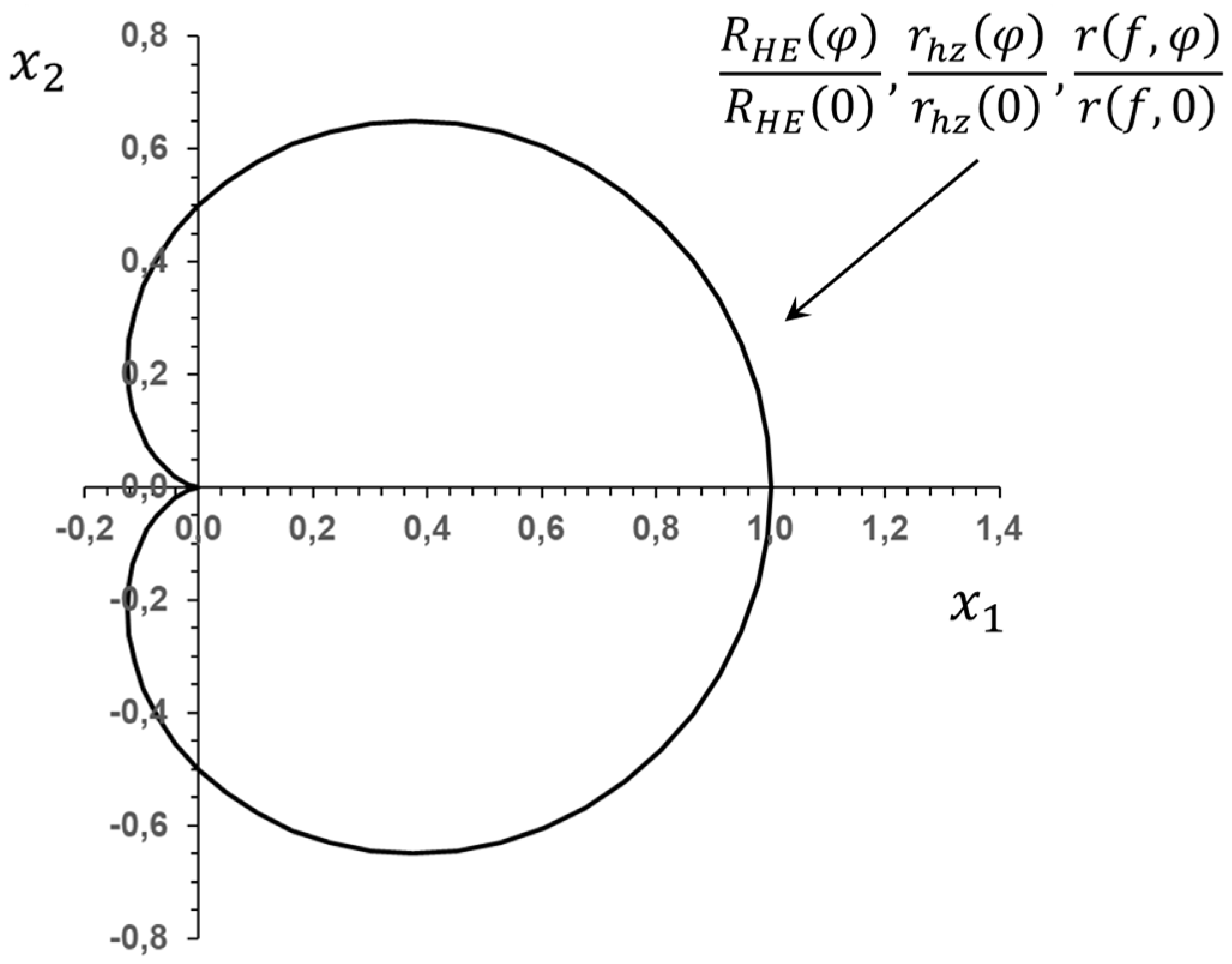
It is interesting to mention that, under the dominance of K-field in the hydrogen-free material and small-scale hydrogen embrittlement, the shape of the hydrogen embrittlement zone, which develops either by hydride precipitation or accumulation of hydrogen in solid solution, is the same, given by following Relation (24) and Figure 2, which are derived based on Relations (16), (22) and (23):
R H E ( φ ) R H E ( 0 ) = r h z ( φ ) r h z ( 0 ) = r ( f , φ ) r ( f , 0 ) = cos 2 φ 2 .
Indeed, Relations (16) and (23), or (22) (corresponding to f = 0 ), are identical, if the following stress trace quantities are correlated/interchanged:
3 V ¯ H R T   l n ( C H | C c r H + T C R e H ) σ h z + Ε Z θ h r 1 2 ν f 3 x θ h r V ¯ h r R T   l n ( C e T S C R e H ) + Ε Z θ h r 1 2 ν f .
In (25), 3 V ¯ H R T   l n ( C H | C c r H + T C R e H ) is the stress trace ahead of the crack tip, which causes hydrogen in solid solution accumulation up to a critical level for material deterioration. 3 x θ h r V ¯ h r R T   l n ( C e T S C R e H ) is the constant stress trace in the hydride precipitation zone and Ε Z θ h r 1 2 ν f corresponds to the reduction in the hydrogen-free material stress trace caused by hydride precipitation. Equivalently, the sum σ h z + Ε Z θ h r 1 2 ν f corresponds to the stress trace at the boundary of critical material deterioration before hydride precipitation.
According to Relations (16), (22) and (23), the size of the hydrogen embrittlement zone is linearly related to energy release rate, G , which equals to ( 1 ν 2 ) Κ Ι 2 / Ε , under plane strain Mode I loading, irrespective of hydrogen embrittlement mechanism.
The above observations facilitate the treatment of hydrogen-induced crack growth initiation within a structural integrity analysis. A more detailed discussion is given in Section 3, where the support of experimental measurements is presented.

2.2. Contained Hydrogen Embrittlement

Contained hydrogen embrittlement is defined as the condition of hydrogen embrittlement of a structure, under which the deteriorated area ahead of the crack exceeds small-scale conditions, i.e., it is not surrounded by a K-field annulus and lies within an annulus of HRR-field dominance [24,25]. If R H E and R i are the size of hydrogen embrittlement area and the inner radius of the annulus of HRR-field dominance, respectively, then, under contained hydrogen embrittlement, R H E < R i . It is noted that R i is defined in a way that hydrogen embrittled area is excluded, as shown in Figure 1 and Relation (1).
As already discussed, in the case of non-hydride-forming alloys, hydrogen in solid solution affects only negligibly the stress distribution. Therefore, under contained hydrogen embrittlement in non-hydride-forming alloys, the deterioration zone may reach HRR annulus, R H E R i , where R H E is defined by Relation (2). On the other hand, in the case of hydride-forming alloys, due to the significant effect of hydride precipitation on the stress field, the hydride precipitation zone lies within HRR-annulus, R H E = r h z < R i . Consequently, in α/β-Ti or Zr alloys, the conditions of contained hydrogen embrittlement become: r h z , α < R i and R H E , β R i , in which r h z , α is the hydride precipitation zone, caused by the precipitation of hydrides in α-phase, and R H E , β is defined by Relation (6). As already mentioned in Section 2.1, under crack-growth initiation in α/β hydride-forming alloys, caused by hydride precipitation, r h z , α > R H E , β , in the case of contained hydrogen embrittlement too.
Under no hydride precipitation, Relations (9)–(15) remain valid. It is emphasized that due to plastic dissipation, the number of trap sites in Relation (11) depends, generally, on accumulated effective plastic strain. In contained hydrogen embrittlement analysis, a constant number of traps could be conservatively assumed, corresponding to the limit at relatively large plastic strains. In addition, S t r a c e 1 of Relation (15), which is the inverse function of the stress trace of the hydrogen-free structure, is derived by the HRR-field. Then, in non-hydride-forming alloys, the extent of hydrogen embrittlement zone satisfies the following relation:
R H E [ σ 0 S ~ k k 3 V ¯ H R T   l n ( C H | C c r H + T C R e H ) ] ( n + 1 ) ( J a σ 0 ε 0 I n ) ,
where σ 0 is equal to the yield stress in tension and ε 0 , ( = σ 0 / Ε ) , to the respective strain at yielding. a is a material constant and n , ( > 1 ) , is the strain hardening exponent of the Ramberg and Osgood [34] stress–strain relation; in the limit as n , non-hardening behavior is approached. J is J-integral [26], I n is a dimensionless constant, which depends on loading mode and hardening, and S ~ k k provides the angular variation of the stress-trace before hydride precipitation, i.e., of the HRR-field [13].
Under hydride precipitation, Relations (18)–(21) are valid. In (21) the inverse of the stress trace function corresponds to HRR-field. Then, the boundary of the hydride precipitation zone is provided by the following relation:
r h z ( σ 0 S ~ k k σ h z ) ( n + 1 ) ( J a σ 0 ε 0 I n ) [ σ 0 S ~ k k 3 x θ h r V ¯ h r R T   l n ( C e T S C R e H ) ] ( n + 1 ) ( J a σ 0 ε 0 I n ) ,
By elaborating on Relations (19), (20) and (27), one derives the part of the hydride precipitation zone, which corresponds to hydride volume fraction larger than a specific value, 0 f < 1 :
r ( f , φ ) ( σ 0 S ~ k k σ h z + Ε Z θ h r 1 2 ν f ) ( n + 1 ) ( J a σ 0 ε 0 I n ) = r h z · ( σ h z σ h z + Ε Z θ h r 1 2 ν f ) ( n + 1 ) .
According to relation (28), the part of the hydride precipitation zone, with hydride volume fraction larger or equal to f , has the same shape as the hydride precipitation zone and size which depends on f , i.e., the size of the hydride precipitation zone multiplied by the ( n +1)-power of σ h z / ( σ h z + Ε Z θ h r 1 2 ν f ) . It is confirmed that, as the hardening exponent, n , tends to 1 and material behavior tends to elastic, Relation (28) tends to (23).
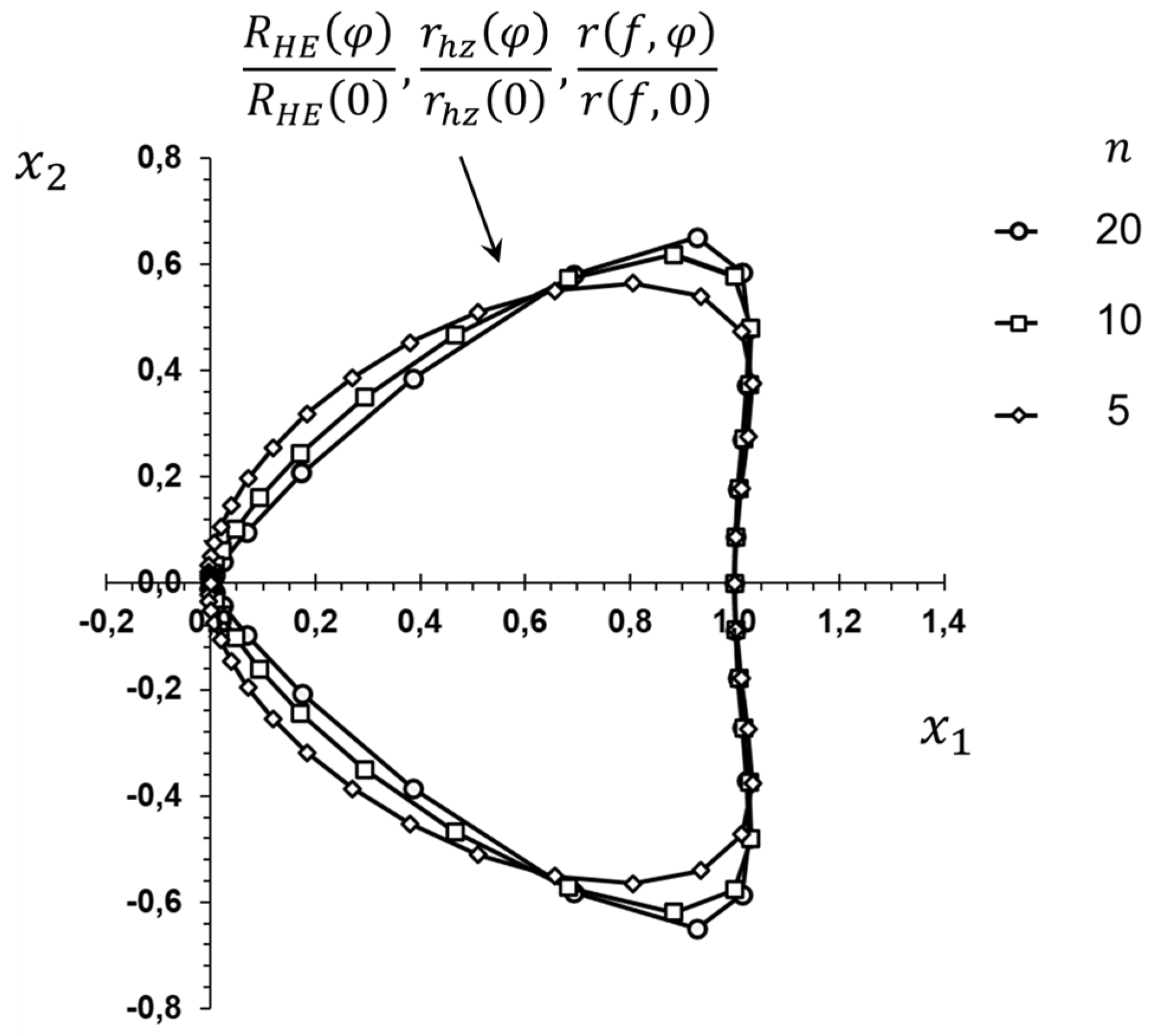
According to Relations (26)–(28), the shape of the hydrogen embrittlement zone, shown in Figure 3, is the same under either hydride precipitation or hydrogen in solid solution. Indeed, according to Relations (26)–(28):
R H E ( φ ) R H E ( 0 ) = r h z ( φ ) r h z ( 0 ) = r ( f , φ ) r ( f , 0 ) = [ S ~ k k ( φ ) S ~ k k ( 0 ) ] ( n + 1 ) .
Relations (26) and (28), or (27) (corresponding to f = 0 ), are identical if the stress-trace correlation (25) is taken into account.
According to Relations (26)–(28), the size of the hydrogen embrittlement zone is linearly related to J-integral, irrespective of hydrogen embrittlement mechanism.

2.3. Large-Scale Hydrogen Embrittlement

Large-scale hydrogen embrittlement is defined as the condition of hydrogen embrittlement of a structure, under which the deteriorated area ahead of the crack exceeds small-scale or contained conditions, i.e., it is not surrounded by K- or HRR-field annulus, even though in the hydrogen-free structure such an annulus of dominance could exist, depending on yielding conditions. Large-scale hydrogen embrittlement occurs when the area of material deterioration, either due to hydrogen accumulation in solid solution or due to hydride precipitation, reaches a size comparable to the characteristic length of the cracked structure, L . In the case of hydrogen embrittlement of non-hydride-forming alloys, the material has reached the level of lowest ductility which does not change with further increase of hydrogen content. On the other hand, in hydride-forming alloys, although hydrides exist everywhere in an area ahead of the crack-tip of size L , parts of the material, where hydrogen is in solid solution, are ductile. Therefore, by increasing hydrogen content and therefore by increasing hydride volume fraction, the energy, required for initiation of crack growth, may further decrease, until a continuous hydride network is reached [35,36,37]. In the following, emphasis is placed on hydride-forming alloys.
The objective is to facilitate the understanding/interpretation of experiments on hydride-forming alloys, such as those discussed in Section 3, which have been performed under large-scale hydrogen embrittlement. Thus, based on this understanding, a methodology of integrity assessment of structures under large-scale hydrogen embrittlement could be provided.
Large-scale hydrogen embrittlement of test specimens is treated by assuming that in the hydrogen-free specimen, an annulus of either K- or HRR-field dominance existed.
A hypothetical cracked specimen is considered, of characteristic length L h s ( L h s > L ), and similar geometry. The size and the hydrogen content of the hypothetical specimen are selected in order to satisfy the following conditions:
C T o t = C h s , R e H L h s L ,
σ h z = σ h s , h z 3 x θ h r V ¯ h r R T l n ( C e T S C h s , R e H ) = 3 x θ h r V ¯ h r R T l n ( C e T S C T o t · L h s L ) ,
where C T o t is the average total hydrogen concentration of the actual specimen under consideration, which includes hydrogen in solid solution and in hydrides. C h s , R e H is the hydrogen concentration in interstitial lattice sites at a reference particle of the hypothetical specimen, far from the crack tip. σ h z is the hydride precipitation zone stress trace of the actual specimen. σ h s , h z is the stress trace in the hydride precipitation zone of the hypothetical specimen. The size of the hypothetical specimen is such that, in the reference particle, hydrogen is only in solid solution. The load considered to be applied in the hypothetical specimen is such that the stress intensity factor or J-integral in the hypothetical specimen is equal to that applied in the actual specimen. In the case of α/β-phase hydride-forming alloys, C h s , R e H and C e T S correspond to α-phase. Boldly stating, a hypothetical specimen is considered, under small-scale or contained hydrogen embrittlement, with the same near-tip stress intensity and total hydrogen content, in order to develop the same near-tip material deterioration as in the actual specimen.
In both specimens, the area of hydride volume fraction, larger or equal to f , is given by the following Relation, when K-field is dominant in the hydrogen-free material:
r ( f , φ ) 2 π ( 1 + ν ) 2 [ Κ Ι 3 x θ h r V ¯ h r R T l n ( C e T S C T o t · L h s L ) + Ε Z θ h r 1 2 ν f ] 2 cos 2 φ 2 ,
or, when HRR-field is dominant in the hydrogen-free material:
r ( f , φ ) [ σ 0 S ~ k k 3 x θ h r V ¯ h r R T l n ( C e T S C T o t · L h s L ) + Ε Z θ h r 1 2 ν f ] ( n + 1 ) ( J a σ 0 ε 0 I n ) .
It is implied that the part of the hydride precipitation zone under consideration is significantly smaller than the characteristic lengths of the specimens, r ( f , φ ) L . Relations (32) and (33) were derived by taking into account that, according to Relation (18) and (20), the same value of stress trace in the hydride precipitation zone and the same value Κ Ι or J lead to the same distributions of stress and hydride volume fraction, ahead of the crack-tip in the hydride precipitation zone. Then the left parts of Relations (23) or (28) can be employed, in which σ h z is given by Relation (31).
In the following Section 3, the relations of the extent of the area of material deterioration under small-scale, contained or large-scale hydrogen embrittlement (i.e., Relations (16), (22)–(23), (26)–(28), (32)–(33)), are used for the development of fracture criteria and the interpretation of fracture measurements of several hydride or non-hydride-forming alloys, including two-phase α/β hydride-forming alloys.

3. Results and Discussion

The effect of hydrogen content on crack-growth initiation, at a constant temperature, is discussed in the present section. All following figures present only experimental data at room temperature, appropriately non-dimentionalized; the trend curves are derived by applying least squares regression on the experimental averages.
According to tensile tests of specimens, either hydrogenated and loaded in an inert atmosphere or loaded in a hydrogen atmosphere, the ductility of non-hydride-forming hydrogen susceptible alloys, such as steel and nickel alloys, is significantly reduced (e.g., [38,39,40,41,42]). According to these experiments, material ductility reaches a minimum with the increase of hydrogen pressure or, equivalently, hydrogen concentration.
Consider a cracked structure, made of a non-hydride-forming alloy, under loading. Based on the experimental evidence, it is assumed that crack growth initiation requires total hydrogen concentration in interstitial lattice sites and reversible traps, reaching a critical level at a critical distance from the tip, which is of the order of grain size:
C H + C T = C c r H + T ,   r = r c r i t .
Furthermore, under small-scale hydrogen embrittlement, crack growth initiation occurs when the threshold stress intensity factor, K I H , is reached. Then by substituting Relation (34) into (16), one derives:
K I H π r c r i t 2 · 1 1 + ν · 3 V ¯ H R T   l n ( C H | C c r H + T C R e H ) .
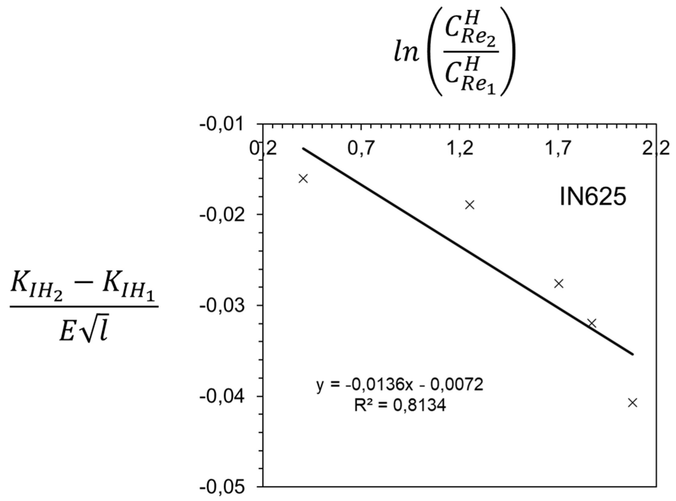
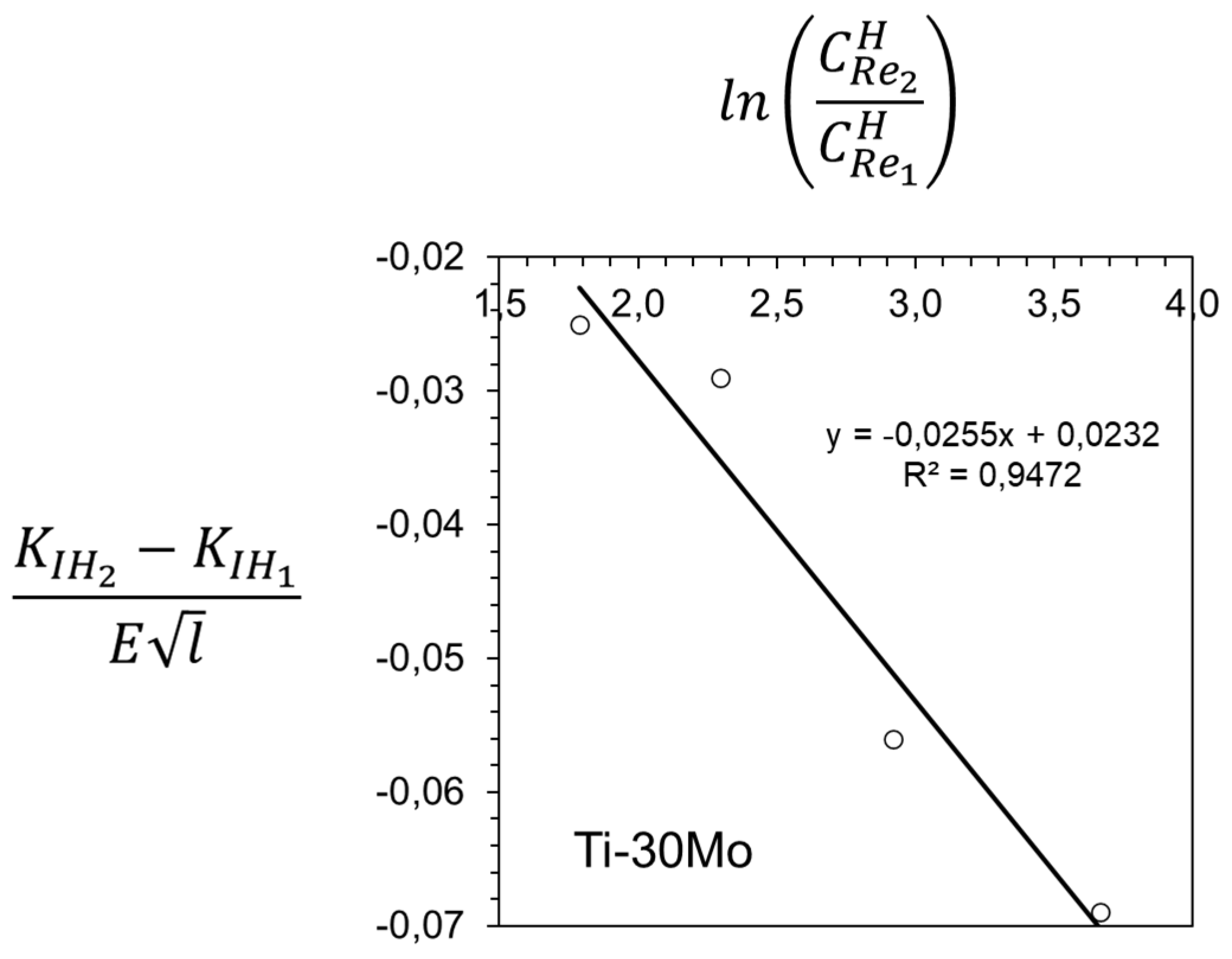
According to Relation (35), the threshold stress intensity factor depends on hydrogen content. If crack growth initiation tests are performed with two specimens, containing two different concentrations of hydrogen, C R e 1 H and C R e 2 H , two different values of threshold are expected to be measured, K I H 1 and K I H 2 . By manipulating Relation (35), a linear relation between the two different values of hydrogen concentrations and thresholds is found:
K I H 2 K I H 1 E l l n ( C R e 2 H C R e 1 H ) ,
where l is related to grain size.
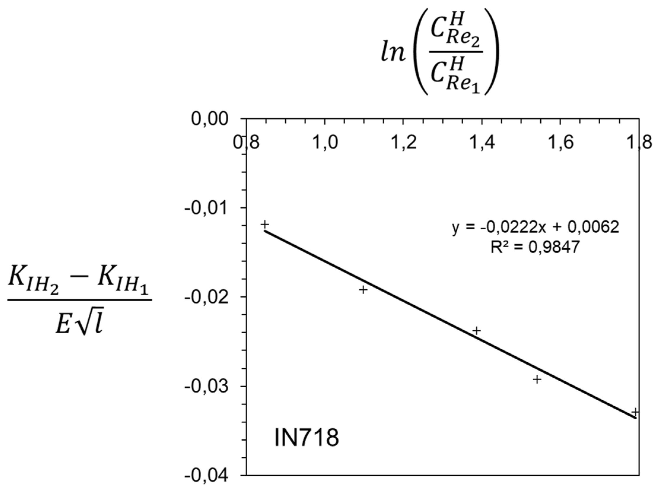
Liner Relation (36) has been confirmed experimentally. Figure 4, Figure 5 and Figure 6 present experimental results measured on nickel-based and β-Ti alloys, where crack growth initiation is caused by hydrogen embrittlement without hydride precipitation. A measure of the deviation of the experimental measurements from linearity is given by the coefficient of determination R2, of least square regression. In all cases R2 approaches unity, thus verifying linearity.
Under contained yielding, the fracture criterion (34) together with Relation (26), leads to a relation for the threshold value of J-integral:
J H a σ 0 ε 0 I n r c r i t [ 3 V ¯ H R T   l n ( C H | C c r H + T C R e H ) σ 0 S ~ k k ] ( n + 1 ) .
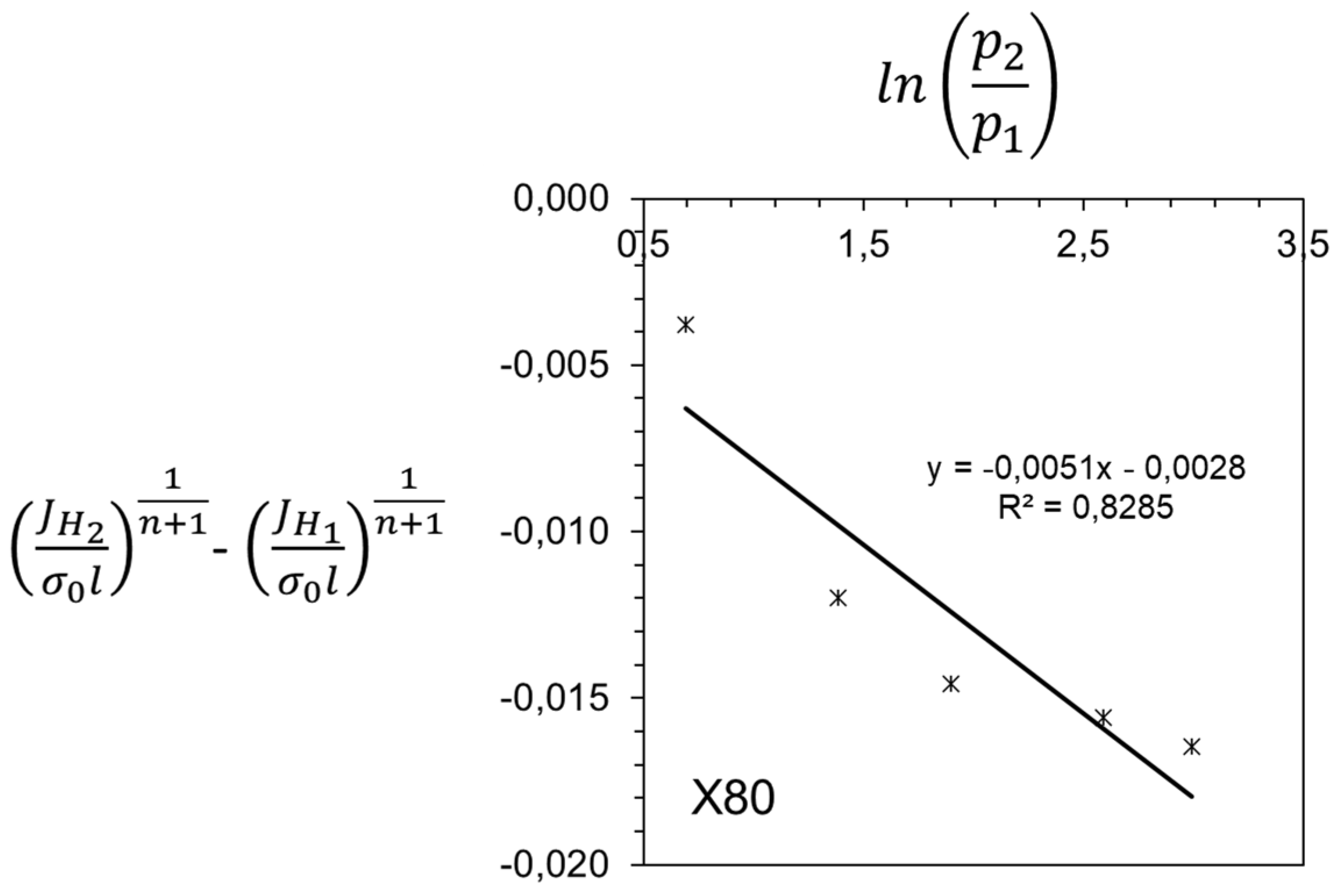
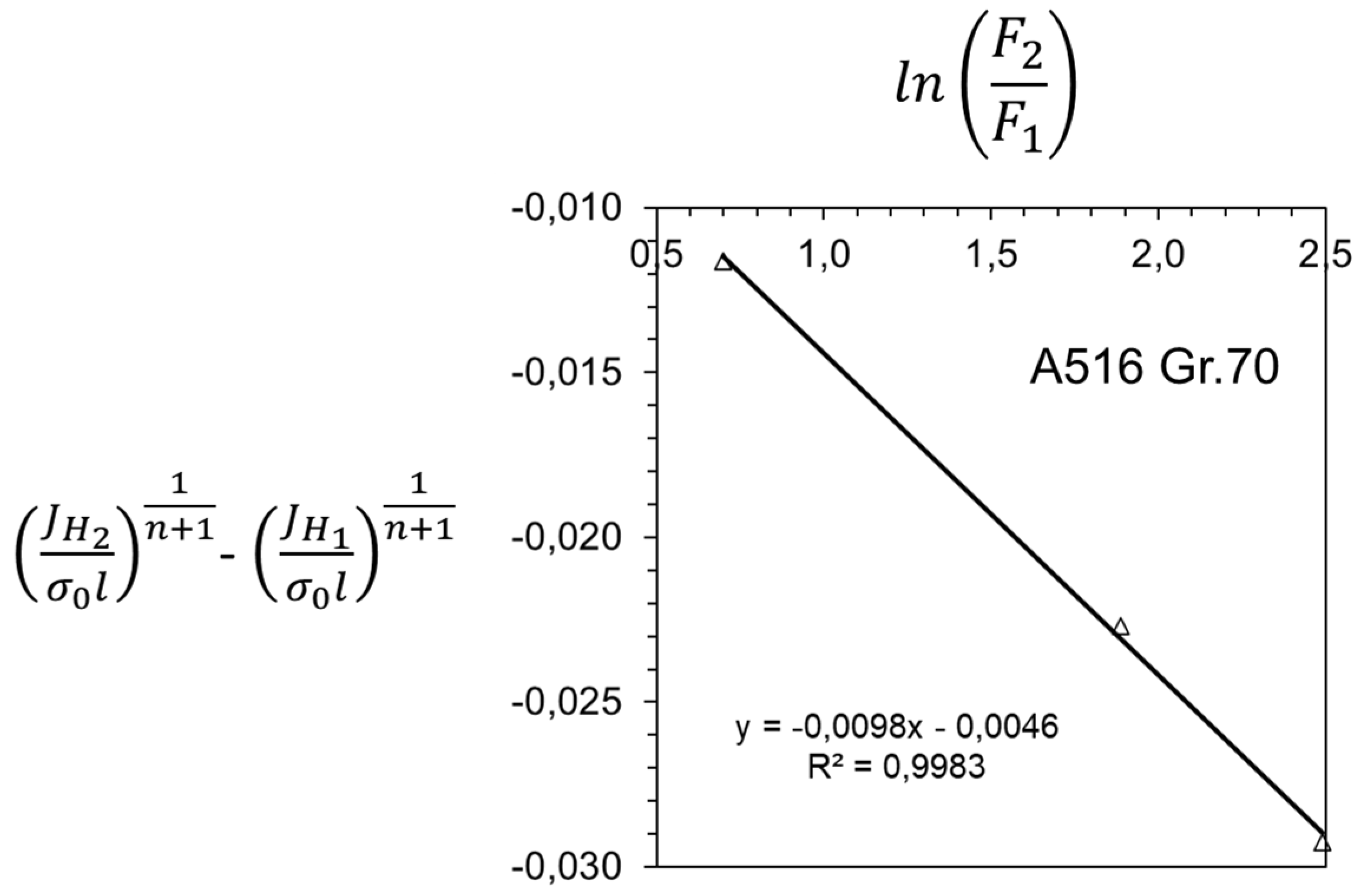
The threshold value of J-integral also depends on hydrogen content. Then, by performing crack growth initiation tests with two different concentrations of hydrogen, C R e 1 H and C R e 2 H , two different values of threshold are expected to be measured, J H 1 and J H 2 . In this case, Relation (37) leads to the following:
( J H 2 σ 0 l ) 1 n + 1 ( J H 1 σ 0 l ) 1 n + 1 l n ( C R e 2 H C R e 1 H ) .
If a specimen or a structure is exposed to a hydrogen pressure, p , then in (36) and (38), C R e H can be replaced by p , taking into account Sievert’s law. In case of relatively high hydrogen pressures, at which the behavior of the gas is not ideal, C R e H can be replaced by hydrogen fugacity, F (e.g., [50,51]). A linear relation between the threshold stress intensity factor and the logarithm of the square-root of hydrogen pressure has been proposed in the past and applied to X45 and X80 steels [52,53] with no consideration of plastic-yielding.
Relation (38) has been confirmed experimentally. Figure 7 and Figure 8 present experimental measurements performed on steels.
In hydride-forming alloys, crack growth initiation is caused by the fracture of the brittle hydrides. Tensile tests of smooth specimens have shown that ductile-brittle transition occurs, and a minimum ductility is reached when a continuous hydride network develops at sufficient hydrogen content and therefore hydride volume fraction, which depends on microstructure [35,36,37]. Ahead of cracks, the embrittlement may occur by the precipitation of either clusters of hydrides (e.g., [18,56]) or single hydrides (e.g., [57]), which is caused by stress-induced attraction of hydrogen in the near-tip area. When clusters of hydrides develop, striations are present on the fracture surface of delayed hydride cracking, the distance of which corresponds to the size of the cluster. In α/β-phase alloys, hydrides precipitate at the boundaries between α- and β-phase grains [58]. In all cases, a critical hydride volume fraction is required, which depends on microstructure. Therefore, crack growth initiation requires the satisfaction of the following criterion:
f = f c r ,   r = r c r i t .
r c r i t is related to the failure mechanisms, corresponding either to a cluster of hydrides, a sequence of hydrides along α/β-grain boundaries or a single hydride and therefore also related to grain size.
In addition, under small-scale or contained hydrogen embrittlement, crack growth initiation occurs when the threshold stress intensity factor, K I H , or the threshold J-integral value, J H , is reached. Then by substituting Relation (39) into (23) or (28), or equivalently by considering the correlation (25) and Relations (35) and (37), one derives:
K I H π r c r i t 2 · 1 1 + ν · [ 3 x θ h r V ¯ h r R T   l n ( C e T S C R e H ) + Ε Z θ h r 1 2 ν f c r ] ,
J H a σ 0 ε 0 I n r c r i t [ 3 x θ h r V ¯ h r R T   l n ( C e T S C R e H ) + Ε Z θ h r 1 2 ν f c r σ 0 S ~ k k ] ( n + 1 ) .
According to Relations (40) and (41), a wide range of thresholds can be achieved under small-scale and contained hydrogen embrittlement conditions. In the case of large-scale hydrogen embrittlement, when K- or HRR-field is dominant before hydride precipitation, C e T S / C R e H shall be replaced by ( C e T S · L h s ) / ( C T o t · L ) , according to Relation (31).
By considering two levels of average hydrogen contents, i.e., two values of C R e H , C R e 1 H and C R e 2 H , which correspond to two levels of hydride precipitation zone stress trace, σ h z 1 and σ h z 2 , two threshold values for crack growth initiation are derived, i.e., K I H 1 and K I H 2 under small-scale hydrogen embrittlement, according to Relation (40), and J H 1 and J H 2 under contained hydrogen embrittlement, according to Relation (41). Then, by elaboration on (40), one may show that Δ K I H   ( = K I H 1 K I H 2 ), appropriately normalized, is proportional to Δ σ h z   ( = σ h z 1 σ h z 2 ) . Similarly, by elaboration on (41), one may show that ( J H 1 σ 0 l ) 1 n + 1 ( J H 2 σ 0 l ) 1 n + 1 is proportional to σ h z 1 σ h z 2 σ 0 , where l is a length related to failure mechanism, hydride length and grain size. Furthermore, Relations (36) and (38) are proven valid, under hydride-induced crack growth. A linear relation between the threshold stress intensity factor and the stress trace of the hydride precipitation zone, by considering the whole extent of the hydride precipitation zone, has also been presented in steady crack growth studies, under small-scale yielding [22].
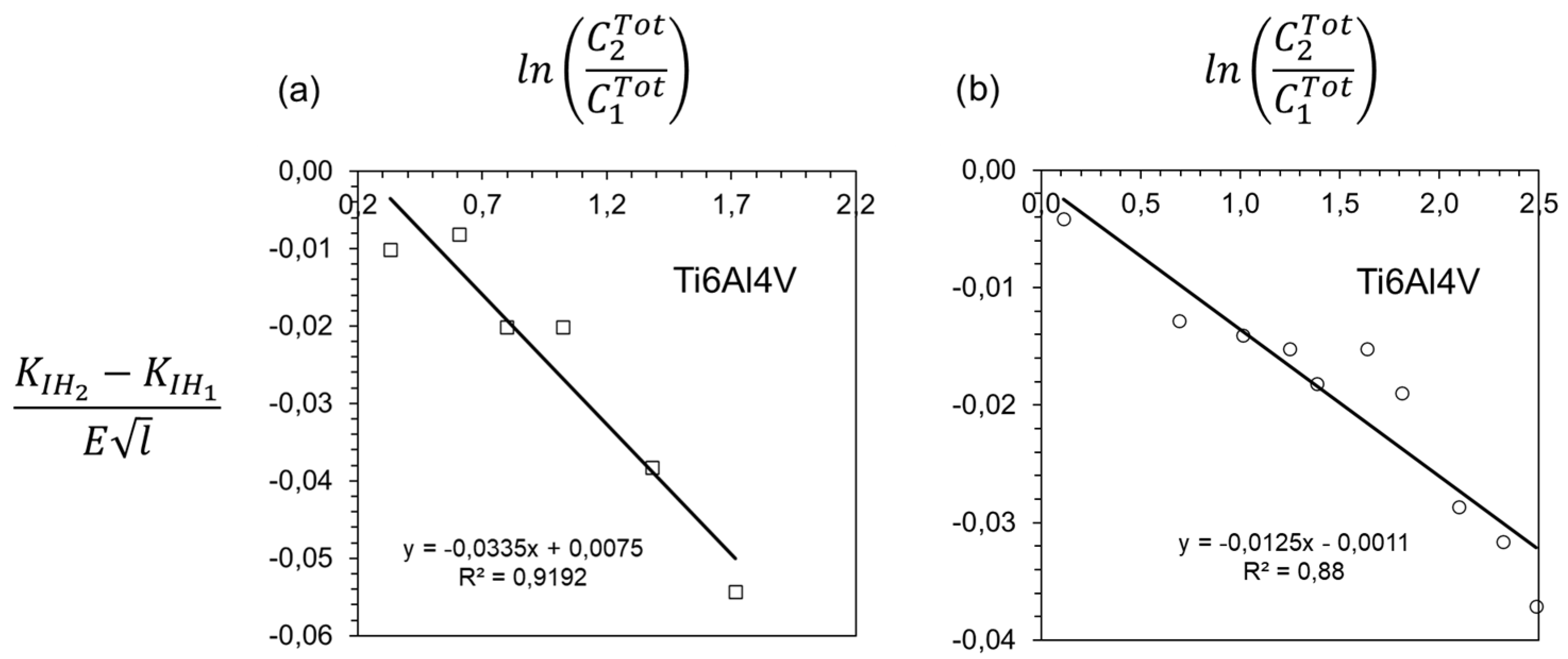
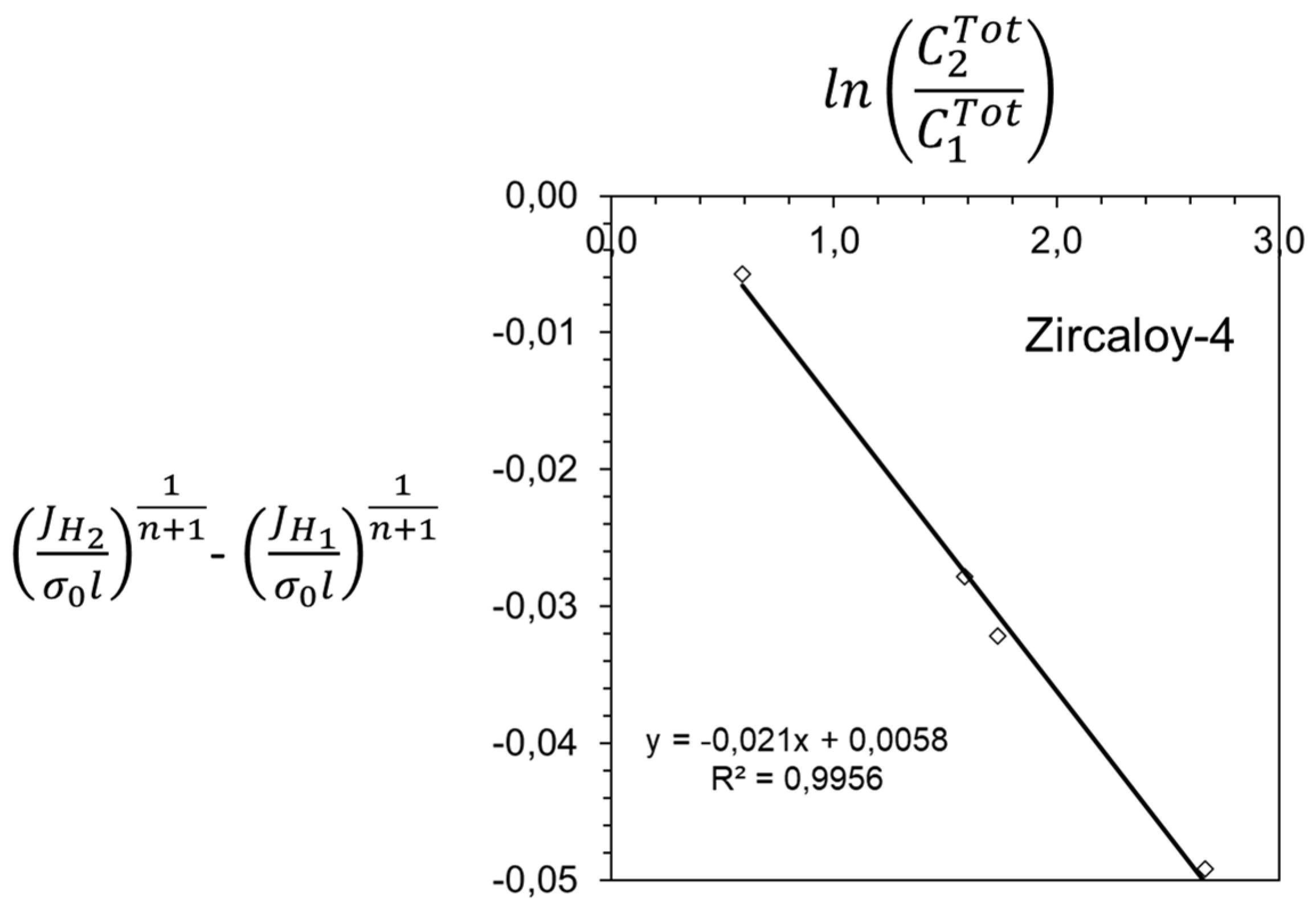
Figure 9 and Figure 10 present experimental confirmation of the validity of Relations (36) and (38) in hydride-forming alloys; all experimental data correspond to measurements on specimens under large-scale hydrogen embrittlement.
All experimental measurements, discussed above, for both non-hydride-forming and hydride-forming alloys, confirm the general analysis of Section 2, related to small-scale, contained and large-scale hydrogen embrittlement and the failure analysis of the present section.
Consider a structure with an initial crack, of characteristic length L , in the presence of hydrogen, introduced either during manufacturing or operation, including the exposure of part of its surface to hydrogen gas. The stress distribution in the hydrogen-free structure is given by S i j , which is derived either analytically or numerically (e.g., by FEM). Under the present analysis, it has to be confirmed that, in the hydrogen-free structure, around the initial crack, there is an annulus of K- or HRR-field dominance, which develops due to mechanical loading alone. Emphasis is placed on the most detrimental mode-I loading. Therefore, K I or J , applied on the structure, are derived. Given the average total hydrogen concentration of the structure, C T o t , any modification of the stress field, in the case of hydride-forming alloys, and the distribution of hydrogen are derived, according to the analysis of Section 2, based on CEFM. If the structure is under small-scale or contained hydrogen embrittlement, C T o t includes only hydrogen in solid solution in interstitial lattice sites and reversible traps. In this case, if C T o t is equal to or larger than the average total hydrogen concentration in the lab-specimen, C R e H + T , subjected also to small-scale or contained hydrogen embrittlement, then satisfaction of the condition K I K I H ( C R e H + T ) or J J I H ( C R e H + T ) implies that Relation (34) or (39) is also satisfied; K I H and J I H are the threshold measurements performed in the lab. Consequently, crack growth initiation in the structure under evaluation occurs. If the structure under evaluation, made of a hydride-forming alloy, is under large-scale hydrogen embrittlement and/or the measurements of the lab specimen have been taken under large-scale hydrogen embrittlement too, then K I or J shall be compared to K I H ( C T o t · L / L l a b ) or J H ( C T o t · L / L l a b ) , where L l a b is the characteristic length of the lab specimen. Thus, in all cases of large-scale hydrogen embrittlement, considered previously, the evaluation is based on the hydrogen content in the structure, over an area of size L , being equal to or larger than the hydrogen content in the lab-specimen, over an area of size L l a b . Detailed analysis, besides K I H and J H (as functions of hydrogen content), derived by standard experiments (either in hydrogen atmosphere or of hydrogenated specimens) and typical mechanical properties of elastic and elastic-plastic deformation, such as elastic moduli, yield stress and hardening exponent, requires the knowledge of hydrogen-related properties, such as hydrogen terminal solid solubility and Sievert’s law parameters. If hydrogen trapping is taken into account, hydrogen trap binding energy and trap concentration are also required. It is worth mentioning that threshold values, K I H and J H , are measured, at the temperature range of interest, under slow strain rate (SSR) conditions specified in the relevant standards (e.g., [64]). These are also the conditions under which the present CEFM analysis is valid. Threshold stress intensity factors are also measured under constant load or constant displacement (e.g., [65]); in these tests, the crack-tip conditions at the threshold correspond to chemical equilibrium, either at crack growth initiation or after arrest. Information on other key material parameters (e.g., Sievert’s law parameters, trap binding energy, trap density, hydride structure, hydride expansion, hydrogen solubility), including experimental procedures for their derivation, is given for various materials, such as steels, Ni-, Ti- and Zr- based alloys, in previous publications and respective references [12,13,14,16,19].
The confirmation of the analysis by independent experimental studies is encouraging. In order to proceed to the development of structural integrity assessment procedures, there is a need for cooperation among several laboratories/scientists/engineers on several materials and geometries. In addition, when, in the hydrogen-free structure, there is no annulus of K- or HRR-field dominance, as in the case of K-T or J-Q field dominance of Constraint-Based Fracture Mechanics, the area of hydrogen-induced material deterioration is affected [12,13]; therefore, the present analysis needs to be extended by including constraint effects. In this case, additional experimental work, together with analysis, is required, which is beyond the scope of the present study. It is also emphasized that, given the hydrogen content of a structure, CEFM application to hydrogen embrittlement can be used for crack growth initiation predictions under steady-state conditions. If further growth or load/environmental transients are of interest, coupled FEM studies could be considered.

4. Conclusions

The present study focuses on hydrogen-induced crack growth initiation in metals under constant temperature and hydrogen chemical equilibrium. Chemical Equilibrium Fracture Mechanics (CEFM) is employed, which is a multidisciplinary approach, based on the assumption of material deterioration under chemical equilibrium. Under CEFM, the coupling of the operating mechanisms of material deformation, hydrogen diffusion and hydride precipitation, is taken into account.
The conditions of small-scale, contained and large-scale hydrogen embrittlement are introduced. Under these conditions, the area of material deterioration is derived analytically, together with the distributions of stresses and hydrogen concentration, including hydride volume fraction of hydride-forming alloys. The presence of hydrogen in reversible traps is taken into account. Two phase, α/β Ti and Zr, alloys are also treated.
It is shown that the shape of the areas of material deterioration is the same in both hydride- and non-hydride-forming alloys and depends on the material’s hardening exponent. This feature is revealed when the stress trace, which attracts hydrogen in non-hydride-forming alloys, is correlated to the constant stress trace of the hydride precipitation zone in hydride-forming alloys. The size of the area of material deterioration increases linearly with energy release rate or J-integral, under K- or HRR-field dominance, respectively, of the initial hydrogen-free structure. The size of the area of material deterioration also increases with the average hydrogen content, which is absorbed during manufacturing and operation.
Failure criteria for non-hydride-forming and hydride-forming alloys are introduced, which are based on a critical hydrogen content over a critical area ahead of the crack tip, dependent on alloy microstructure. Based on these criteria, it is shown that the threshold stress intensity factor or the 1 / ( n + 1 ) -power of the threshold value of J-integral, for hydrogen-induced crack growth initiation, depend linearly on the logarithm of average hydrogen concentration, where n is material hardening exponent. This linear relation is confirmed by independent experimental measurements on several non-hydride- and hydride-forming alloys, including α/β Ti6Al4V, published in the literature.
Based on the present study, integrity assessments of metallic structures/equipment in a hydrogen environment under steady-state operation can be performed analytically, without relying on complicated coupled numerical analysis of material deformation, hydrogen diffusion and hydride precipitation.
Structural integrity analysis, based on CEFM, is applicable to threshold conditions of environment/hydrogen assisted cracking, especially useful at initial design and required by design regulations. Under conditions of transient environmental/mechanical loading, cyclic loading, stage II environment-assisted cracking (i.e., at approximately constant crack growth velocity), stage III environment-assisted cracking and relatively fast mechanical loading, when hydrogen-free material fracture behavior is approached, the present CEFM structural integrity assessment directions are not recommended.

Funding

This research received no external funding.

Data Availability Statement

The original contributions presented in this study are included in the article. Further inquiries can be directed to the corresponding author.

Acknowledgments

The study was performed within Euro-Harmonization and Engineering, an activity for the understanding of mechanics, related to present and future industrial needs.

Conflicts of Interest

The author declares no conflicts of interest.

References

  1. Global Hydrogen Review 2025; International Energy Agency: Paris, France, 2025.
  2. Nuttal, W.J.; Powel, J.B.; Anaya-Stucchi, K.L.; Bakenne, A.T.; Wilson, A. Insights into the New Hydrogen Economy; Springer Nature: Cham, Switzerland, 2025. [Google Scholar]
  3. Quitzow, R.; Zabanova, Y. The geopolitics of hydrogen. In European Strategies in Global Perspective; Springer Nature: Cham, Switzerland, 2024; Volume 1. [Google Scholar]
  4. Brewer, T. Climate change. In An Interdisciplinary Introduction; Springer Nature: Cham, Switzerland, 2023. [Google Scholar]
  5. Weichenhain, U. Hydrogen transportation. In The Key to Unlocking the Clean Hydrogen Economy; Roland Berger: Munich, Germany, 2021. [Google Scholar]
  6. Suresh, S. Fatigue of Materials; Cambridge University Press: Cambridge, UK, 1991. [Google Scholar]
  7. Broberg, K.B. Cracks and Fracture; Academic Press: London, UK, 1999. [Google Scholar]
  8. Kanninen, M.F.; Popelar, C.H. Advanced Fracture Mechanics; Oxford University Press: Oxford, UK, 1985. [Google Scholar]
  9. Hutchinson, J.W. A Course on Nonlinear Fracture Mechanics; The Technical University of Denmark: Lyngby, Denmark, 1979. [Google Scholar]
  10. Chen, Y.-S.; Huang, C.; Liu, P.-Y.; Yen, H.-W.; Niu, R.; Burr, P.; Moore, K.L.; Martínez-Pañeda, E.; Atrens, A.; Cairney, J.M. Hydrogen trapping and embrittlement in metals—A review. Int. J. Hydrogen Energy 2025, 136, 789–821. [Google Scholar] [CrossRef]
  11. Barrera, O.; Bombac, D.; Chen, Y.; Daff, T.D.; Galindo-Nava, E.; Gong, P.; Haley, D.; Horton, R.; Katzarov, I.; Kermode, J.R.; et al. Understanding and mitigating hydrogen embrittlement of steels: A review of experimental, modelling and design progress from atomistic to continuum. J. Mater. Sci. 2018, 53, 6251–6290, Correction in J. Mater. Sci. 2018, 53, 10593–10594.. [Google Scholar] [CrossRef]
  12. Varias, A.G. Elastic crack-tip field in hydride forming metals under hydrogen chemical equilibrium. Int. J. Fract. 2024, 245, 183–194. [Google Scholar] [CrossRef]
  13. Varias, A.G. Elastic-plastic crack-tip field in hydride forming metals under hydrogen chemical equilibrium. Int. J. Fract. 2024, 246, 47–57. [Google Scholar] [CrossRef]
  14. Varias, A.G. Hydride induced embrittlement and fracture of non-hardening metals under hydrogen chemical equilibrium. Int. J. Solids Struct. 2024, 305, 113073. [Google Scholar] [CrossRef]
  15. Behvar, A.; Haghshenas, M.; Djukic, M.B. Hydrogen embrittlement and hydrogen-induced crack initiation in additively manufactured metals: A critical review on mechanical and cyclic loading. Int. J. Hydrogen Energy 2024, 58, 1214–1239. [Google Scholar] [CrossRef]
  16. Varias, A.G. Chemical Equilibrium Fracture Mechanics–Hydrogen embrittlement application. Corros. Mater. Degrad. 2025, 6, 5. [Google Scholar] [CrossRef]
  17. Li, X.; Zhong, Y.; Li, H.; Liu, Y.; Shan, G.; Qu, D.; Zhang, J.; Djukic, M.B. Review of hydrogen embrittlement effect on fracture toughness of metallic materials: Influencing factors, and predictive models. Eng. Fract. Mech. 2025, 327, 111392. [Google Scholar] [CrossRef]
  18. Coleman, C.E. The Metallurgy of Zirconium; International Atomic Energy Agency: Vienna, Austria, 2022; Volume 3. [Google Scholar]
  19. Varias, A.G. Chemical Equilibrium Fracture Mechanics–Hydrogen embrittlement of two-phase hydride forming alloys. Int. J. Solids Struct. 2025, 323, 113635. [Google Scholar] [CrossRef]
  20. ASME B31.12; Hydrogen Piping and Pipelines. The American Society of Mechanical Engineers: New York, NY, USA, 2023.
  21. ASME BPVC; Boiler and Pressure Vessel Code. The American Society of Mechanical Engineers: New York, NY, USA, 2025.
  22. Varias, A.G.; Feng, J.L. Simulation of hydride-induced steady-state crack growth in metals—Part I: Growth near hydrogen chemical equilibrium. Comput. Mech. 2004, 34, 339–356. [Google Scholar] [CrossRef]
  23. Williams, M.L. On the stress distribution at the base of a stationary crack. J. Appl. Mech. 1957, 24, 109–114. [Google Scholar] [CrossRef]
  24. Hutchinson, J. Singular behaviour at the end of a tensile crack in a hardening material. J. Mech. Phys. Solids 1968, 16, 13–31. [Google Scholar] [CrossRef]
  25. Rice, J.R.; Rosengren, G.F. Plane strain deformation near a crack tip in a power-law hardening material. J. Mech. Phys. Solids 1968, 16, 1–12. [Google Scholar] [CrossRef]
  26. Rice, J.R. A path independent integral and the approximate analysis of strain concentration by notches and cracks. J. Appl. Mech. 1968, 35, 379–387. [Google Scholar] [CrossRef]
  27. Oriani, R. The diffusion and trapping of hydrogen in steel. Acta Metall. 1970, 18, 147–157. [Google Scholar] [CrossRef]
  28. Nagumo, M. Fundamentals of Hydrogen Embrittlement; Springer Nature: Singapore, 2023. [Google Scholar]
  29. Krom, A.H.M.; Bakker, A. Hydrogen trapping models in steel. Metall. Mater. Trans. B 2000, 31, 1475–1482. [Google Scholar] [CrossRef]
  30. Nabarro, F.R.N. The strains produced by precipitation in alloys. Proc. R. Soc. 1940, 175, 519–538. [Google Scholar] [CrossRef]
  31. Eshelby, J.D. The determination of the elastic field of an ellipsoidal inclusion, and related problems. Proc. R. Soc. 1957, 241, 376–396. [Google Scholar] [CrossRef]
  32. Lee, J.K.; Earmme, Y.Y.; Aaronson, H.I.; Russell, K.C. Plastic relaxation of the transformation strain energy of a misfitting spherical precipitate: Ideal plastic behavior. Metall. Trans. A 1980, 11, 1837–1847. [Google Scholar] [CrossRef]
  33. Earmee, Y.Y.; Johnson, W.C.; Lee, J.K. Plastic relaxation of the transformation strain energy of a misfitting spherical precipitate: Linear and power-law strain hardening. Metall. Trans. A 1981, 12, 1521–1530. [Google Scholar] [CrossRef]
  34. Ramberg, W.; Osgood, W.R. Description of Stress-Strain Curves by Three Parameters; NACA, TN 902; NASA: Washington, DC, USA, 1943. [Google Scholar]
  35. Bai, J.; François, D. Some evidence of a brittle-ductile transition of zirconium hydride between 20 and 350 °C. J. Nucl. Mater. 1992, 187, 186–189. [Google Scholar] [CrossRef]
  36. Bai, J.B.; Prioul, C.; François, D. Hydride embrittlement in zircaloy-4: Part I. influence of microstructure on the hydride embrittlement in zircaloy-4 at 20 °C and 350 °C. Metall. Mater. Trans. A 1994, 25, 1185–1197. [Google Scholar] [CrossRef]
  37. Arsene, S.; Bai, J.B.; Bompard, P. Hydride embrittlement and irradiation effects on the hoop mechanical properties of pressurized water reactor (PWR) and boiling-water reactor (BWR) zircaloy cladding tubes: Part I. hydride embrittlement in stress-relieved, annealed, and recrystallized zircaloys at 20 °C and 300 °C. Metall. Mater. Trans. A 2003, 34, 553–566. [Google Scholar]
  38. Ebling, F.; Bratsch, P.; Wagner, S.; Pundt, A.; Preußner, J.; Oesterlin, H.; Wackermann, K.; Michler, T. Assessing hydrogen embrittlement of alloy 718: Hollow and conventional tensile tests. Eng. Fract. Mech. 2025, 319, 111028. [Google Scholar] [CrossRef]
  39. Hamed, A.; Beschliesser, M.; Fink, S.; Mori, G. Assessment of the suitability of an existing L360NB natural gas pipeline for hydrogen transport using the hollow specimen technique. J. Mater. Res. Technol. 2025, 36, 8942–8952. [Google Scholar] [CrossRef]
  40. Symons, D.M.; Thompson, A.W. The effect of hydrogen on the fracture of alloy X-750. Metall. Mater. Trans. A 1996, 27, 101–110. [Google Scholar] [CrossRef]
  41. Gray, H.R. Hydrogen Environment Embrittlement; TM X-68088; NASA: Washington, DC, USA, 1972. [Google Scholar]
  42. Rhythm, S.; Ahmed, R.; Ahmed, N.; Gyaabeng, M.; Teodoriu, C. Experimental study of the impact of hydrogen embrittlement on the ductility of natural gas pipeline steels. Gas Sci. Eng. 2025, 143, 205746. [Google Scholar] [CrossRef]
  43. Hicks, P.D.; Altstetter, C.J. Hydrogen-enhanced cracking of superalloys. Metall. Trans. A 1992, 23, 237–249. [Google Scholar] [CrossRef]
  44. INCONEL® alloy 718; Publication No. SMC-045; Special Metals Corporation: Huntington, WV, USA, 2007.
  45. INCONEL® alloy 625; Special Metals Corporation: Huntington, WV, USA, 2013.
  46. Katz, Y.; Tymiak, N.; Gerberich, W. Nanomechanical probes as new approaches to hydrogen/deformation interaction studies. Eng. Fract. Mech. 2001, 68, 619–646. [Google Scholar] [CrossRef]
  47. de Araújo, R.O.; Ayako Goto Donato, T.; dos Santos Jorge Sousa, K.; Akira Bazaglia Kuroda, P.; Grandini, C.R. Unveiling the effect of Mo on the crystal structure of β-BCC, microhardness, elastic modulus, and biocompatibility in titanium alloys. J. Alloys Compd. Commun. 2025, 6, 100076. [Google Scholar] [CrossRef]
  48. Martins, J.R.J.R.S.; Araújo, R.O.; Nogueira, R.A.; Grandini, C.R. Internal friction and microstructure of Ti and Ti-Mo alloys containing oxygen. Arch. Metall. Mater. 2016, 61, 25–30. [Google Scholar] [CrossRef]
  49. Jata, K.V.; Gerberich, W.W.; Beevers, C.J. Low-temperature fatigue crack propagation in a β-titanium alloy. In Fatigue at Low Temperatures; Stephens, R.I., Ed.; ASTM STP 857; American Society for Testing and Materials: Philadelphia, PA, USA, 1985; pp. 102–120. [Google Scholar]
  50. Denbigh, K.G. The Principles of Chemical Equilibrium; Cambridge University Press: Cambridge, UK, 1955. [Google Scholar]
  51. San Marchi, C.; Somerday, B.P.; Robinson, S.L. Permeability, solubility and diffusivity of hydrogen isotopes in stainless steels at high gas pressures. Int. J. Hydrogen Energy 2007, 32, 100–116. [Google Scholar] [CrossRef]
  52. Kim, Y.; Chao, Y.J.; Pechersky, M.J.; Morgan, M.J. On the effect of hydrogen on the fracture toughness of steel. Int. J. Fract. 2005, 134, 339–347. [Google Scholar] [CrossRef]
  53. Wei, H.; Tang, H.; Xing, B.; Shang, J.; Qiu, S.; Hua, Z.; Gu, C. Research on the fracture toughness of pipeline steel X80 in a hydrogen environment. Eng. Fail. Anal. 2025, 180, 109917. [Google Scholar] [CrossRef]
  54. API 5L. Specification for Line Pipe; American Petroleum Institute: Washington, DC, USA, 2018.
  55. Somerday, B.P. Technical Reference on Hydrogen Compatibility of Materials. Plain Carbon Ferritic Steels: C-Mn Alloys (Code 1100); SAND2008-1163; Sandia National Laboratories: Albuquerque, NM, USA, 2008. [Google Scholar]
  56. Efsing, P. Delayed Hydride Cracking in Irradiated Zircaloy. Ph.D. Thesis, Royal Institute of Technology, Stockholm, Sweden, 1998. [Google Scholar]
  57. Kubo, T.; Kobayashi, Y.; Uchikoshi, H. Measurements of delayed hydride cracking propagation rate in the radial direction of Zircaloy-2 cladding tubes. J. Nucl. Mater. 2012, 427, 18–29. [Google Scholar] [CrossRef]
  58. Nelson, H.G.; Williams, D.P.; Stein, J.E. Environmental hydrogen embrittlement of an α-β titanium alloy: Effect of microstructure. Metall. Trans. 1972, 3, 469–475. [Google Scholar] [CrossRef]
  59. Senkov, O.N.; Dubois, M.; Jonas, J.J. Elastic moduli of titanium-hydrogen alloys in the temperature range 20 °C to 1100 °C. Metall. Mater. Trans. A 1996, 27, 3963–3970. [Google Scholar] [CrossRef]
  60. Gu, J.; Hardie, D. Effect of hydrogen on the tensile ductility of Ti6Al4V—Part II Fracture of pre-cracked tensile specimens. J. Mater. Sci. 1997, 32, 609–617. [Google Scholar] [CrossRef]
  61. Hardie, D.; Ouyang, S. Effect of hydrogen and strain rate upon the ductility of mill-annealed Ti6Al4V. Corros. Sci. 1999, 41, 155–177. [Google Scholar] [CrossRef]
  62. Bertolino, G.; Meyer, G.; Perez Ipiña, J.E. In situ crack growth observation and fracture toughness measurement of hydrogen charged Zircaloy-4. J. Nucl. Mater. 2003, 322, 57–65. [Google Scholar] [CrossRef]
  63. Rosinger, H.; Northwood, D. The elastic properties of zirconium alloy fuel cladding and pressure tubing materials. J. Nucl. Mater. 1979, 79, 170–179. [Google Scholar] [CrossRef]
  64. ASTM G129; Standard Practice for Slow Strain Rate Testing to Evaluate the Susceptibility of Metallic Materials to Environmentally Assisted Cracking. The American Society for Testing and Materials: West Conshohocken, PA, USA, 2021.
  65. ASTM E 1681; Standard Test Method for Determining Threshold Stress Intensity Factor for Environment-Assisted Cracking of Metallic Materials. The American Society for Testing and Materials: West Conshohocken, PA, USA, 2023.
Figure 1. Illustration of small-scale and contained hydrogen embrittlement conditions. The hydrogen embrittlement area, which develops ahead of the crack-tip, lies within the annulus of dominance of the asymptotic crack-tip field in the hydrogen-free material. R i is the inner radius of the annulus of the asymptotic field, which remains unaffected by hydrogen embrittlement. In the case of large-scale hydrogen embrittlement, the area of hydrogen embrittlement spreads beyond the annulus of the asymptotic crack-tip field in the hydrogen-free material.
Cmd 07 00020 g001
Figure 2. Shape of hydrogen embrittlement zone, caused by either hydride precipitation or accumulation of hydrogen in solid solution, under small-scale hydrogen embrittlement.
Cmd 07 00020 g002
Figure 3. Shape of hydrogen embrittlement zone, caused by either hydride precipitation or accumulation of hydrogen in solid solution, under contained hydrogen embrittlement and various values of material hardening exponent.
Cmd 07 00020 g003
Figure 4. Variation of threshold stress intensity factor with specimen hydrogen content in the case of IN718. The experimental measurements have been performed by Hicks and Altstetter [43] on single-edge notched tensile specimens. In non-dimensionalizing the experimental data: Young’s modulus, E , is taken equal to 199.9 GPa, at room temperature, according to data of the manufacturer [44]. The grain size is equal to 30 μm, measured by Hicks and Altstetter [43]. The ratios of average hydrogen concentration, given in the experimental studies, are taken equal to the ratios of C R e H , considering small occupancy of interstitial and trap sites far from the crack-tip.
Cmd 07 00020 g004
Figure 5. Variation of threshold stress intensity factor with specimen hydrogen content in the case of IN625. The experimental measurements have been performed by Hicks and Altstetter [43] on single-edge notched tensile specimens. In non-dimensionalizing the experimental data: Young’s modulus, E , is taken equal to 207,5 GPa, at room temperature, according to data of the manufacturer [45]. The grain size is equal to 11 μm, measured by Hicks and Altstetter [43]. The ratios of average hydrogen concentration, given in the experimental studies, are taken equal to the ratios of C R e H , considering small occupancy of interstitial and trap sites far from the crack-tip.
Cmd 07 00020 g005
Figure 6. Variation of threshold stress intensity factor with specimen hydrogen content in the case of Ti-30Mo. The experimental measurements are given by Katz et al. [46]. In non-dimensionalizing the experimental data: Young’s modulus, E , is taken equal to 100 GPa [47,48]. The grain size is taken equal to 100 μm [47,49]. The ratios of average hydrogen concentration, given in the experimental studies, are taken equal to the ratios of C R e H , considering small occupancy of interstitial and trap sites far from the crack-tip.
Cmd 07 00020 g006
Figure 7. Variation of J-integral at crack growth initiation with hydrogen pressure, applied on CT specimens, in the case of X80 [53]. In non-dimensionalizing the experimental data: Young’s modulus, E , Poisson’s ratio, ν , initial yield stress, σ 0 , ultimate tensile strength, hardening exponent, n , and grain size, l , are taken equal to 210 GPa, 0,3, 660 MPa, 724 MPa, 90 and 2,21 μm, respectively. Yield stress, ultimate tensile strength and grain size are given by Wei et al. [53] and used to calculate the hardening exponent, based on API 5L elongation at fracture [54].
Cmd 07 00020 g007
Figure 8. Variation of J-integral at crack growth initiation with hydrogen fugacity, in the case of A516 Gr.70 [55]. In non-dimensionalizing the experimental data: Young’s modulus, E , Poisson’s ratio, ν , initial yield stress, σ 0 , ultimate tensile strength, elongation at fracture, hardening exponent, n , and grain size, l , are taken equal to 210 GPa, 0,3, 375 MPa, 535 MPa, 0,17, 26 and 35 μm, respectively. Yield stress, ultimate tensile strength, elongation at fracture and grain size are given by Somerday [55] and used to calculate the hardening exponent. Hydrogen fugacity was calculated, based on hydrogen pressures, given by Somerday [55] and the constitutive relation given by San Marchi et al. [51].
Cmd 07 00020 g008
Figure 9. Variation of threshold stress intensity factor with specimen hydrogen content in the case of Ti6Al4V. In non-dimensionalizing the experimental data: Young’s modulus, E , is taken equal to 113,28 GPa, at room temperature, based on data provided by Senkov et al. [59]. l is equal to the grain size (20 μm [60]), related to hydride size and r c r i t . (a) Experimental measurements performed by Gu and Hardie [60] on compact tension specimens. (b) Experimental measurements performed by Hardie and Quyang [61] on compact tension specimens. The experimental data correspond to the hydrogen embrittlement sub-critical crack growth regime, above about 100 ppm of hydrogen [60,61].
Cmd 07 00020 g009
Figure 10. Variation of J-integral at crack growth initiation with hydrogen content in single-edge-notched three point bending specimens, in the case of Zircaloy-4 [62]. l is equal to hydride size. In non-dimensionalizing the experimental data: Young’s modulus, E , initial yield stress, σ 0 , ultimate tensile strength, elongation at fracture, hardening exponent, n , and hydride size, l , are taken equal to 94,6 GPa, 365 MPa, 522 MPa, 27,8%, 25 and 100 μm, respectively. Young’s modulus is given in [63]. The hardening exponent is calculated based on yield stress, ultimate tensile stress and elongation at fracture, given by Bertolino et al. [62].
Cmd 07 00020 g010
Table 1. List of symbols and respective definitions, used in the present analysis.
DefinitionSymbol
Concentrations of hydrogen in solid solution in interstitial lattice sites C H
Concentrations of hydrogen in solid solution in interstitial lattice sites of β-phase in α/β hydride-forming alloys C β H
Concentrations of hydrogen in solid solution in interstitial lattice sites at critical hydrogen concentration C H | C c r H + T
Concentrations of hydrogen in solid solution in interstitial lattice sites in a reference particle C R e H
Concentrations of hydrogen in solid solution in interstitial lattice sites of α-phase in a reference particle of an α/β hydride-forming alloy C α , R e H
Concentrations of hydrogen in solid solution in interstitial lattice sites in a reference particle of a hypothetical specimen, used in the analysis, under large-scale hydrogen embrittlement C h s , R e H
Critical hydrogen concentration in solid solution in interstitial lattice sites and reversible traps, which specifies the area of hydrogen embrittlement, in non-hydride-forming alloys C c r H + T
Critical hydrogen concentration in solid solution in interstitial lattice sites and reversible traps, which specifies the area of hydrogen embrittlement of β-phase in α/β hydride-forming alloys C c r , β H + T
Hydrogen concentration in solid solution in interstitial lattice sites and reversible traps at a reference particle C R e H + T
Concentrations of hydrogen in reversible traps C T
Concentrations of hydrogen in reversible traps of β-phase in α/β hydride-forming alloys C β T
Average total hydrogen concentration of a structure or a lab-specimen, which may include hydrogen in solid solution and in hydrides C T o t
Terminal solid solubility of hydrogen in the metal, under no applied stress C e T S
Terminal solid solubility of hydrogen of α-phase in an α/β hydride-forming alloy, under no applied stress C e , α T S
Young’s modulus E
Hydrogen gas fugacity F
Hydride volume fraction f
Critical hydride volume fraction at a critical distance ahead of a crack-tip, required for fracture f c r
Energy release rate G
HRR-field dimensionless constant, which depends on loading mode and hardening I n
J-integral J
Hydrogen embrittlement threshold value of J-integral J H
Chemical equilibrium constant of hydrogen in interstitial lattice sites and reversible traps K e q
Stress intensity factor K I
Hydrogen embrittlement threshold stress intensity factor K I H
Characteristic length related to failure mechanism, grain size and/or hydride length l
Characteristic length of a structure L
Characteristic length of a hypothetical specimen, used in the analysis, under large-scale hydrogen embrittlement L h s
Characteristic length of a lab-specimen L l a b
Hardening exponent of Ramberg and Osgood stress–strain relation n
Avogadro’s number N A
Number of interstitial lattice sites per unit volume, divided by Avogadro’s number N I
Number of reversible trap sites per unit volume, divided by Avogadro’s number N T
Hydrogen gas pressure p
Cylindrical coordinate system ( r , φ ,   x 3 )
Gas constant R
Coefficient of determination of least square regressionR2
Critical distance ahead of a crack tip at which hydrogen concentration in solid solution or hydride volume fraction reaches a critical value, required for fracture r c r i t
Radial distance of a material particle with hydride volume fraction equal to f r ( f )
Size of hydrogen embrittlement area R H E
Size of hydrogen embrittlement area of α-phase in α/β hydride-forming alloys R H E , α
Size of hydrogen embrittlement area of β-phase in α/β hydride-forming alloys R H E , β
Size of hydride precipitation zone r h z
Size of hydride precipitation zone of α-phase in α/β hydride-forming alloys r h z , α
Inner radius of the annulus of the crack-tip asymptotic field, which remains unaffected by hydrogen embrittlement R i
Plastic zone size r p
Stress tensor of the hydrogen-free material S i j
HRR-field stress trace angular variation S ~ k k
Inverse function of the stress trace of the hydrogen-free structure S t r a c e 1
Temperature T
Molal volume of hydrogen in solid solution V ¯ H
Hydride molal volume V ¯ h r
Mole fraction of hydrogen in the hydride of type MHx x
Cartesian coordinate system ( x 1 ,   x 2 ,   x 3 )
Material constant of Ramberg and Osgood stress–strain relation a
Trap binding energy Δ E T
Strain at yielding in tension ε 0
Stress-free hydride-induced expansion at a material particle ε i j H , c e
Constrained hydride-induced expansion at a material particle ε i j c e
Correlation factor of stress-free and constrained hydride-induced expansion at a material particle Z
Hydride expansion strain θ h r
Fraction of occupied interstitial lattice sites θ I
Fraction of occupied reversible trap sites θ T
Poisson’s ratio ν
A measure of applied stress, related to the stress intensity factor σ
Yield stress in tension σ 0
Stress trace in the hydride precipitation zone σ h z
Stress trace in the hydride precipitation zone of a hypothetical specimen, used in the analysis, under large-scale hydrogen embrittlement σ h s ,   h z
Stress tensor in the presence of hydrogen σ i j
Stress trace in a reference particle σ R e
Disclaimer/Publisher’s Note: The statements, opinions and data contained in all publications are solely those of the individual author(s) and contributor(s) and not of MDPI and/or the editor(s). MDPI and/or the editor(s) disclaim responsibility for any injury to people or property resulting from any ideas, methods, instructions or products referred to in the content.