Article

Tribocorrosion and Stress Corrosion Cracking Risk Assessment of Novel Hybrid Stainless Steel–Carbon Fibre Tubes

1
Department of Industrial Engineering, University of Padova, Via Marzolo 9, 35131 Padova, Italy
2
Institute of Condensed Matter Chemistry and Technologies for Energy, National Research Council of Italy (CNR), Corso Stati Uniti 4, 35127 Padova, Italy
*
Author to whom correspondence should be addressed.
Corros. Mater. Degrad. 2025, 6(2), 22; https://doi.org/10.3390/cmd6020022
Submission received: 10 March 2025 / Revised: 19 May 2025 / Accepted: 30 May 2025 / Published: 3 June 2025

Abstract

:
The increasing demand for lightweight, high-performance materials in marine and offshore engineering has driven the development of hybrid solutions combining metals and composites. This study investigates the stress corrosion cracking (SCC) and tribocorrosion behaviour of a novel hybrid wire consisting of a superaustenitic stainless steel (6Mo) outer shell and a carbon fibre-reinforced polymer (CFRP) core. Microstructural analysis, residual stress measurement, and corrosion testing were performed to assess the integrity of the welded structure under harsh conditions. The results revealed that residual stresses and interdendritic segregation in the weld zone significantly contribute to SCC susceptibility, while the 6Mo steel showed improved corrosion resistance over 316L under tribocorrosion conditions but was more sensitive to the sliding frequency. These findings provide critical insights into the degradation mechanisms of metal composite hybrid wires and support the future design of corrosion-resistant components for offshore and structural applications.

1. Introduction

In the modern engineering landscape, the demand for lightweight, high-performance materials has pushed steel ropes to their operational limits [1]. Their increasing weight, less-than-ideal fatigue characteristics, and susceptibility to corrosion pose significant challenges in their application [2]. As a consequence, novel synthetic and composite alternatives are garnering increasing interest within the market. Fibre-reinforced plastics (FRPs) [2], carbon-reinforced polymers (CFRPs) [3], and other synthetic fibre-based materials have emerged as strong candidates, finding extensive application in domains that were previously dominated by steel [4]. These synthetic fibres, particularly CFRPs, possess impressive mechanical properties such as high tensile strength, stiffness, and creep resistance [4,5]. Despite their advantages, limitations in wear resistance, heat tolerance, and susceptibility to environmental factors restrict their suitability to low- and medium-duty applications [2,6]. Therefore, stainless steel wires and tubes still remain the most commonly used materials in most applications.
In the past decade, there has been growing interest in combining CFRPs and traditional stainless steel tubes to produce more effective and reliable components by developing lightweight composites. One prominent example is fibre–metal laminates (FMLs), which are valued for their exceptional impact resilience, fatigue endurance, and corrosion resistance, finding applications in the aerospace industry [7]. Similarly, CFRP–steel hybrid cable designs have been proposed, primarily for cable-stayed bridges. Xiong et al. [8] pioneered this concept by proposing three different cable geometries with varying CFRP-to-steel area ratios. These geometries included a central CFRP wire surrounded by steel wires, and a final configuration featuring multiple CFRP wires encased within a single steel sheath. Cai et al. [9] subsequently built upon Xiong’s work by developing an algorithm for optimizing the area ratio. However, the existing literature on CFRP–steel hybrid cables presents several limitations. Firstly, there is a lack of research beyond numerical simulations, with limited focus on practical manufacturing techniques and experimental testing of these novel products. Additionally, a significant gap exists regarding material selection and its impact on corrosion resistance. This includes factors such as localized corrosion and susceptibility to stress corrosion cracking (SCC), which have received minimal attention in existing studies.
The European project FIRST-WIRE (patent WO 2013/065074 A1) addresses the limitations of both steel and synthetic fibres by proposing a novel hybrid solution. This innovative approach seeks to synergistically combine the superior strength of high-performance fibres with the established durability and corrosion resistance of steel. The FIRST-WIRE comprises an outer casing of austenitic stainless steel, welded around a pultruded CFRP bar core. FIRST-WIRE technology is specifically designed for demanding applications, such as deep-water offshore abandonment and recovery operations, heavy lifting, mooring lines for floating platforms, and structural cables in civil engineering projects. These applications necessitate materials with exceptional resistance to pitting, crevice corrosion, and SCC. The high chloride content in such harsh environments poses a significant challenge for conventional stainless steel grades, necessitating a focus on material selection for optimal performance [10]. The hybrid tubular structure investigated in this study is based on a patented composite wire design (EP 2 773 810 B1), consisting of an internal CFRP core encased within a welded superaustenitic stainless steel (X1CrNiMoCuN20-18-7, or 6Mo) outer shell. This configuration has been specifically engineered to address the limitations of traditional metallic or fibre-based wire systems used in offshore and structural applications. The innovation lies in the coaxial composite structure, where the outer steel mantle provides corrosion resistance, structural integrity, and protection from mechanical wear and environmental exposure, while the CFRP core offers significant reductions in weight and high tensile strength. The fusion of these materials creates a synergy that enables the hybrid tube to maintain mechanical reliability under extreme marine conditions, including high humidity, salt exposure, dynamic loading, and stress corrosion-prone environments. The welded stainless steel mantle is designed to ensure full encapsulation of the CFRP, mitigating direct exposure to environmental agents and reducing vulnerability to microcrack propagation, delamination, and moisture ingress. Compared to conventional metallic wires such as those made entirely from 316L stainless steel, the hybrid design achieves a notable decrease in dead weight, up to approximately 50% in air and up to 60% in submerged conditions, without compromising mechanical or tribological performance.
AISI F44/6Mo1 (X1CrNiMoCuN20-18-7) is a superaustenitic stainless steel, specifically formulated for exceptional resistance against crevice corrosion, pitting, and SCC due to its precisely tailored composition of alloying elements [11]. However, a frequent manufacturing method for these tubes (the bending and welding of a metal sheet) can introduce vulnerabilities, particularly regarding corrosion resistance [12,13,14]. Welding processes can introduce two main concerns that compromise the otherwise superior corrosion resistance of AISI F44/6Mo1. Firstly, the high temperatures involved during welding can lead to sensitization. This phenomenon involves the precipitation of chromium carbide at the heat-affected zone (HAZ), which is well-documented to cause intergranular corrosion [15,16]. Secondly, residual stresses induced by welding can worsen the effects of applied loads, potentially leading to SCC [17,18,19,20,21].
The critical nature of FIRST-WIRE applications in demanding environments demands precise attention to safety and reliability. This necessitates accurate material selection and comprehensive evaluations of product performance. This study undertakes a detailed characterization of FIRST-WIRE’s key properties, with a particular focus on potential corrosion-related vulnerabilities. It is noteworthy that the susceptibility of these hybrid wires to SCC has not been previously investigated. To our knowledge, no existing research addresses these specific concerns. Therefore, this work presents a comprehensive assessment of corrosion risks, recognizing that localized corrosion in marine and offshore environments poses significant challenges that could potentially counter the benefits of enhanced mechanical properties.
This study delves into the tribocorrosion and SCC behaviour of the innovative hybrid wires, featuring an external superaustenitic stainless steel sheath and an internal core of carbon fibres. Various standard techniques were utilized to fully characterize the risk of corrosion and SCC occurrence in the novel hybrid wires, accompanied by microstructural characterization of the wires. The present study hypothesizes that the novel FIRST-WIRE structure, comprising a superaustenitic steel outer jacket and a CFRP core, may exhibit a distinct susceptibility to SCC under simulated offshore service conditions. The research seeks to evaluate this susceptibility relative to traditional 316L stainless steel components. Specifically, the work aims to determine whether the hybrid configuration offers advantages or presents additional challenges when exposed to the combined mechanical loading and harsh environmental factors that are typical of marine and offshore applications. Such characterizations could provide valuable insights into the mechanisms of SCC occurrence in hybrid wires, assisting both scientific and industrial investors in adapting wire production strategies to mitigate SCC risk, an issue of considerable relevance to the ongoing development and safe implementation of hybrid wire technologies.

2. Materials and Methods

2.1. Materials

Hybrid FIRST-WIRE composite wires are formed by an external shell in X1CrNiMoCuN20-18-7 (composition reported in Table 1) and an internal core of pultruded CFRP. The CFRP’s fibre volumetric fraction is around 60%. The wire manufacturing method starts from a steel strip, which is tungsten inert gas (TIG) welded around the CFRP core. No epoxy adhesive is utilized for enhanced interfacial bonding.

2.2. Microstructural Analysis

A microstructural examination of the wire cross-section was conducted to reveal the morphology and distribution of various phases. Short wire segments were sectioned and hot-mounted in a phenolic resin using a compression moulding technique at a maximum temperature of 180 °C for 10 min. The mounted samples were then ground and polished using standard metallographic techniques, achieving a final polishing step with a 1 µm colloidal silica suspension to obtain a mirror-like surface. To enhance the contrast between different microstructural constituents, electro-etching with a 10% oxalic acid solution was performed for 10 s at a voltage of 6V. Microstructural observations were carried out using a Leica DMRE optical microscope (OM) (Leica, Singapore) and a ZEISS EVO MA 10 scanning electron microscope (SEM) (ZEISS, Oberkochen, Germany).

2.3. X-Ray Residual Stress Analysis

Residual stress measurements were performed using X-ray diffraction (XRD) with a portable Sider-X diffractometer (GNR S.r.l., Novara, Italy) equipped with Cr Kα radiation (filtered with vanadium). The sin2Ψ method was employed, involving the collection of nine data points across an optimized ψ-tilt range of −35° to +35°. Each data point acquisition utilized a dwell time of 100 s to ensure a sufficient signal-to-noise ratio. To enhance the reliability of the measurements, three independent measurements were taken for each sample, ensuring a minimum fitting accuracy of 98%.

2.4. Tribocorrosion Analysis

Tribocorrosion tests were performed using a CETR-UMT2 tribometer (Bruker, Billerica, MA, USA) equipped with an open-cell configuration that was suitable for combined mechanical and electrochemical evaluation. The setup allowed for precise control of the normal load, sliding frequency, and stroke length and enabled in situ monitoring of the coefficient of friction. The test environment consisted of a 3.5 wt% NaCl solution to simulate marine conditions. The tribometer was selected for its flexibility in replicating service-relevant tribomechanical conditions and for its compatibility with electrochemical integration, essential for assessing wear–corrosion synergy in the hybrid CFRP-6Mo structure.
The tribocorrosion testing was conducted using a CETR-UMT2 tribometer, configured for ball-on-flat geometry. This configuration employs reciprocating linear motion at the sample stage, ensuring pure sliding contact (no rolling component) with the spherical counterbody, as specified by ASTM G119. During the test, the applied normal load, friction force, vertical displacement of the ball, temperature, and open-circuit potential (OCP) of the wear sample (referenced to an Ag/AgCl electrode) were continuously monitored.
An open-cell tribocorrosion test was developed, encompassing three phases with a total duration of 120 min, and repeated three times for each condition to ensure result repeatability. The test comprised OCP stabilization (OCP1): 30 min to establish a stable baseline potential; wear (sliding): 60 min of reciprocating sliding wear; and OCP stabilization (OCP2): 30 min to monitor potential recovery after the wear phase.
A 5 mm diameter Al2O3 sphere with a certified hardness of 1500 HV was utilized as the counterbody for all tests. To evaluate the material’s response under tribocorrosion, two Hertzian contact pressure levels (750 MPa and 1.5 GPa) and two reciprocating frequencies (2 Hz and 5 Hz) were selected. Following the tribocorrosion tests, the samples were characterized using stylus profilometry (wear rate determination) and SEM-EDS analysis of the produced wear tracks. The tribocorrosion behaviour of the superaustenitic stainless steel that was employed for the tube was compared to that of a standard AISI 316L stainless steel.

2.5. SCC Susceptibility

Stress corrosion cracking tests were carried out according to the ASTM G36-94 standard [22]. Six samples were prepared by U-bending half of them at 90° to produce a state of stress. Then, the samples were immersed in boiling magnesium chloride under controlled evaporation/condensation for 1 h and observed using SEM and the optical microscope.

3. Results

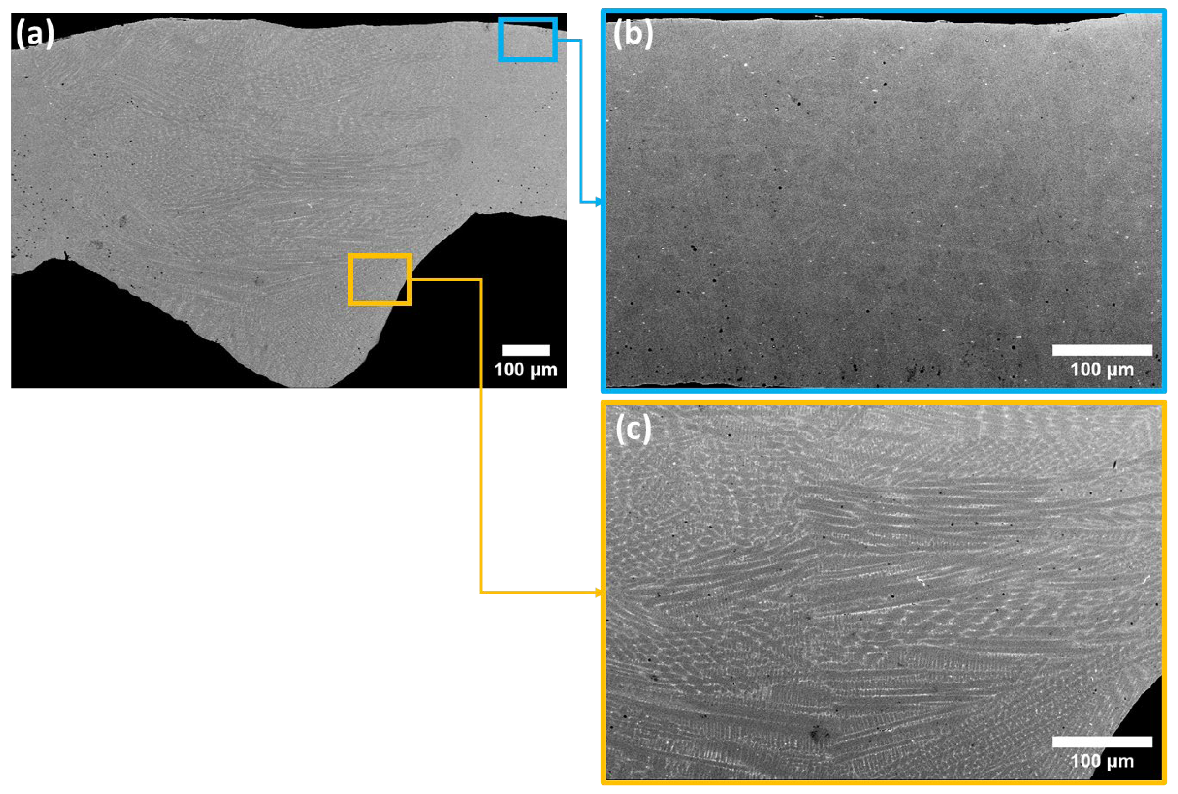
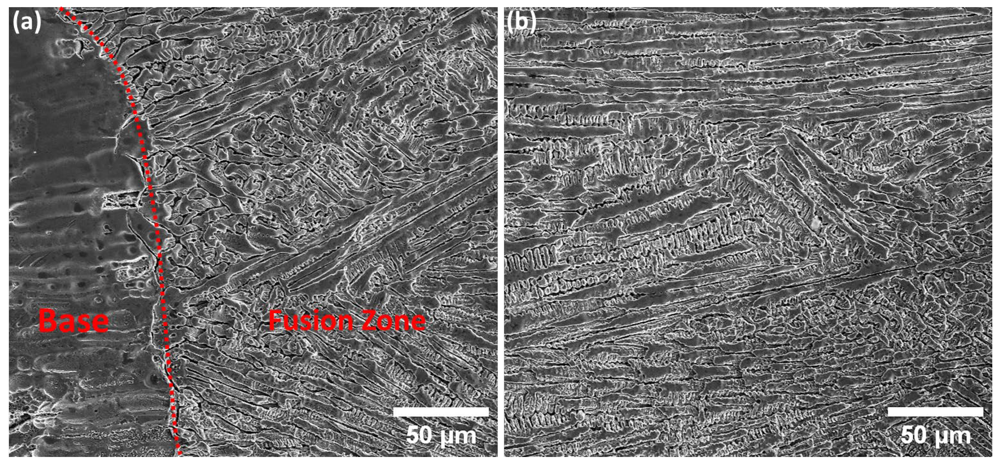
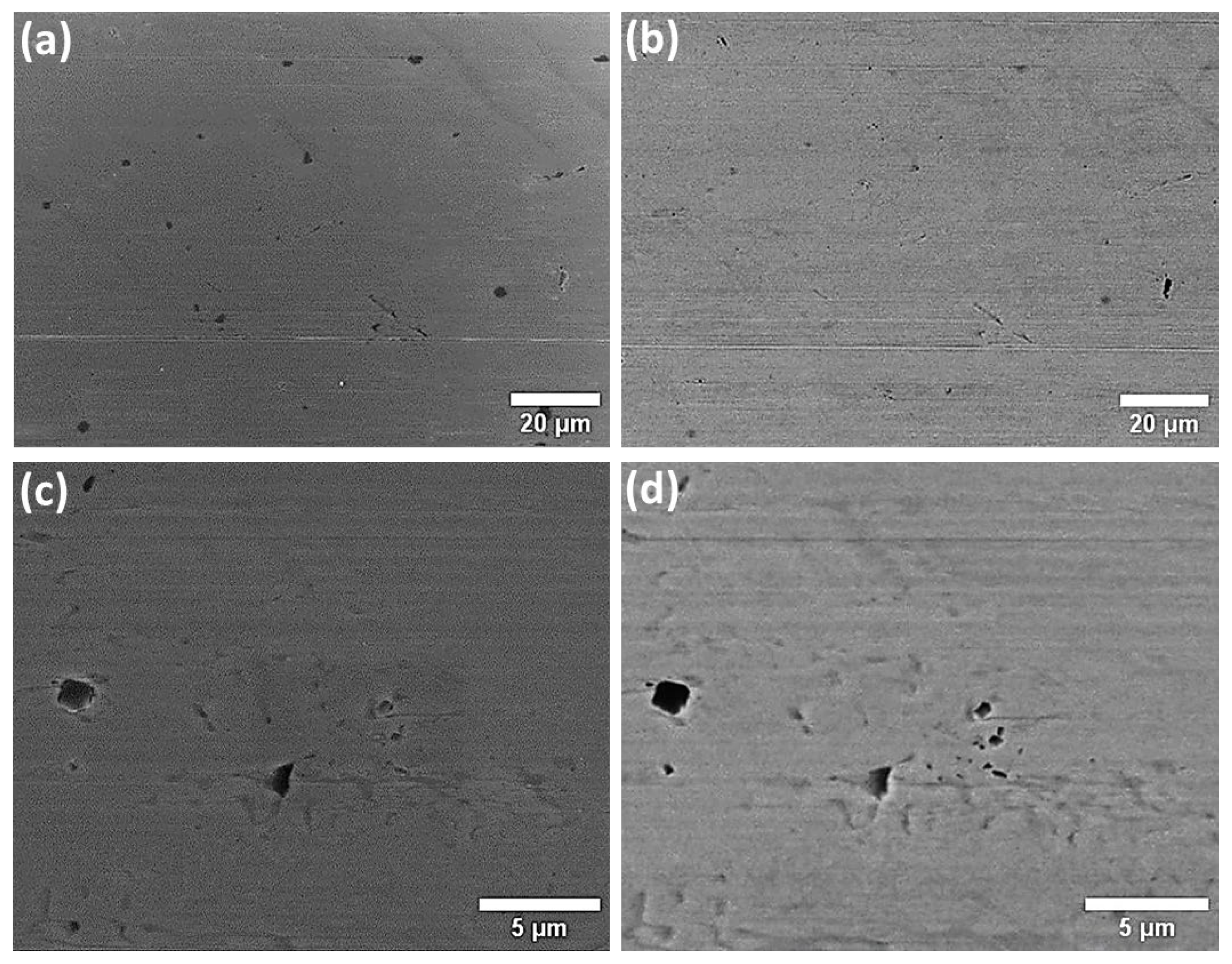
3.1. Microstructural Characterization

The microstructural analysis of the hybrid wire’s cross-section shown in Figure 1 reveals a distinct microstructure shaped by the processing history. The most prominent feature is the elongated grain morphology, particularly in the circumferential direction. This elongated structure is a direct consequence of the prior plastic deformation experienced by the stainless steel sheet during directional cold rolling, a crucial step in wire preparation. This technique is well-known for inducing extensive plastic deformation, leading to the elongation and alignment of grains along the rolling direction [23,24,25].
An examination of the TIG-welded region, as shown in Figure 1c, reveals distinct microstructural features compared to the base metal. The presence of a dendritic structure with primary and secondary arms suggests directional solidification originating from the base metal. However, a well-defined HAZ is absent under the current welding conditions. This observation can be attributed to two contributing factors. Firstly, the limited thickness of the metallic component likely restricts the total heat input during TIG welding, minimizing the area that is exposed to temperatures exceeding the melting point. Secondly, the presence of the CFRP core plays a significant role in promoting heat dissipation [26,27,28]. The thermal conductivity of CFRP surpasses that of air at atmospheric pressure, facilitating efficient heat transfer away from the weld zone towards the CFRP core. This rapid cooling process further restricts the formation of a prominent HAZ. The absence of a substantial HAZ offers potential advantages for the overall performance of the hybrid wire. The HAZ is typically characterized by residual stresses, microstructural alterations, and reduced corrosion resistance, making it more susceptible to localized corrosion forms like pitting and SCC [29,30,31,32]. Therefore, minimizing the extent of the HAZ, as observed in this case due to the combined effects of the limited heat input and efficient heat dissipation, can potentially enhance the overall corrosion resistance of the welded joint.
Further investigation using SEM analysis of the HAZ and fusion zone after etching as depicted in Figure 2 reveals evidence of segregation within the interdendritic regions. Segregation refers to the non-uniform distribution of alloying elements during solidification [33,34,35,36,37,38]. Certain elements, particularly chromium, molybdenum, and silicon, have a stronger affinity for the solid phase and tend to be rejected ahead of the advancing solidification front [33].

3.2. Residual Stress Analysis

Measurements of residual stress in both the longitudinal and transverse (radial) directions of the hybrid wire revealed significant values. The average residual stress in the longitudinal direction was measured to be 300 ± 30 MPa, while the radial direction exhibited a higher value of 800 ± 40 MPa. These substantial residual stress levels can be directly attributed to the wire’s manufacturing history. The production process for the hybrid wire utilizes a cold-rolled metal strip that is subsequently bent to prepare the samples for TIG welding. This cold rolling process induces significant plastic deformation, particularly in the circumferential direction of the strip. This plastic deformation is a primary contributor to the high residual stresses measured in the radial direction of the finished wire.
Furthermore, the production process for the hybrid wire utilizes a cold-rolled metal strip that is subsequently bent to prepare the samples for TIG welding. This cold rolling process induces significant plastic deformation, particularly in the circumferential direction of the strip. This plastic deformation is a primary contributor to the high residual stresses measured in the radial direction of the finished wire. The presence of high residual stresses can have detrimental effects on the performance of the hybrid wire. They can reduce its fatigue strength, promote SCC, and potentially lead to dimensional instability [39,40,41].

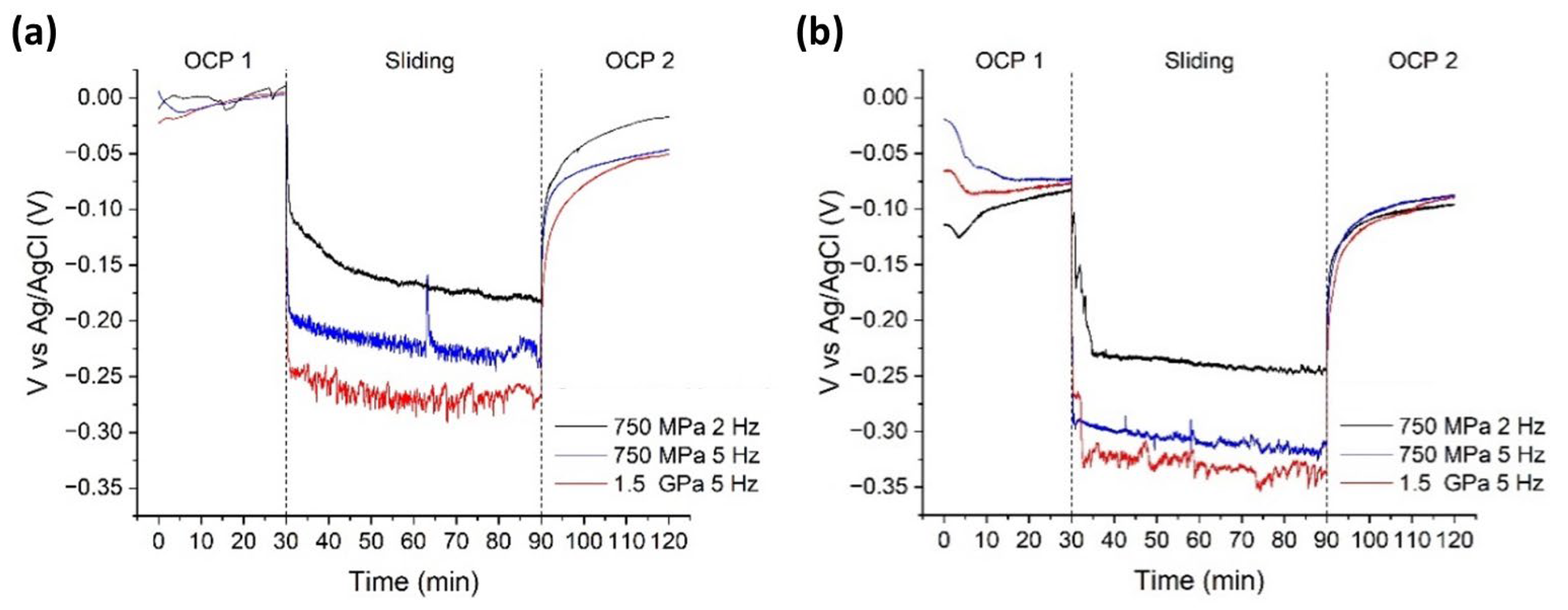
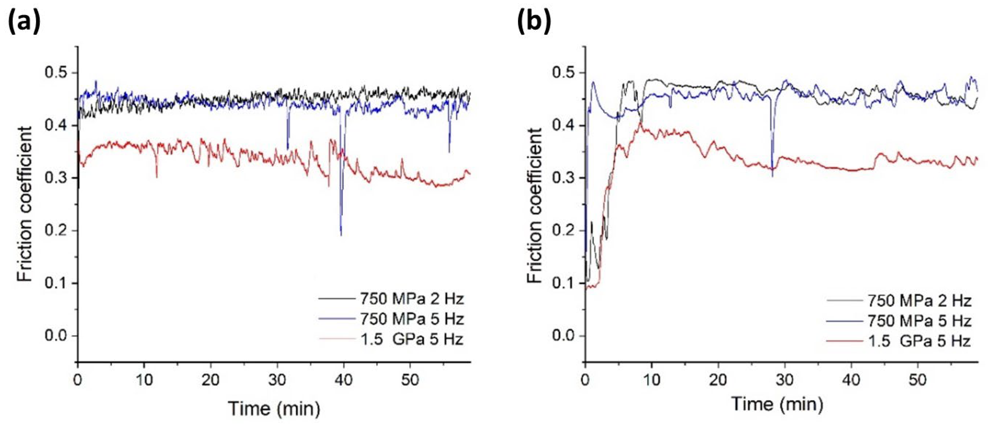
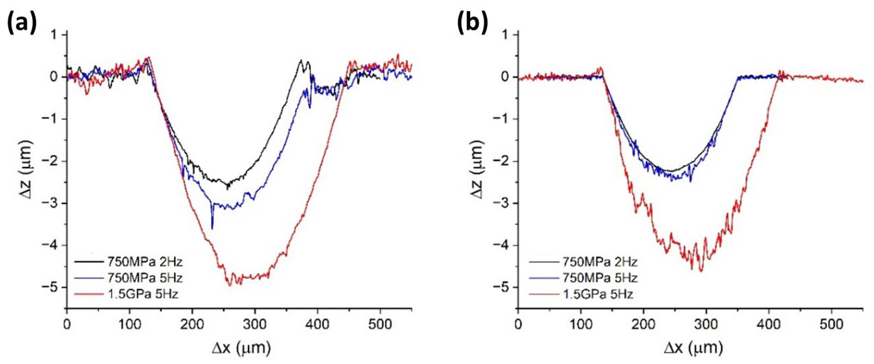
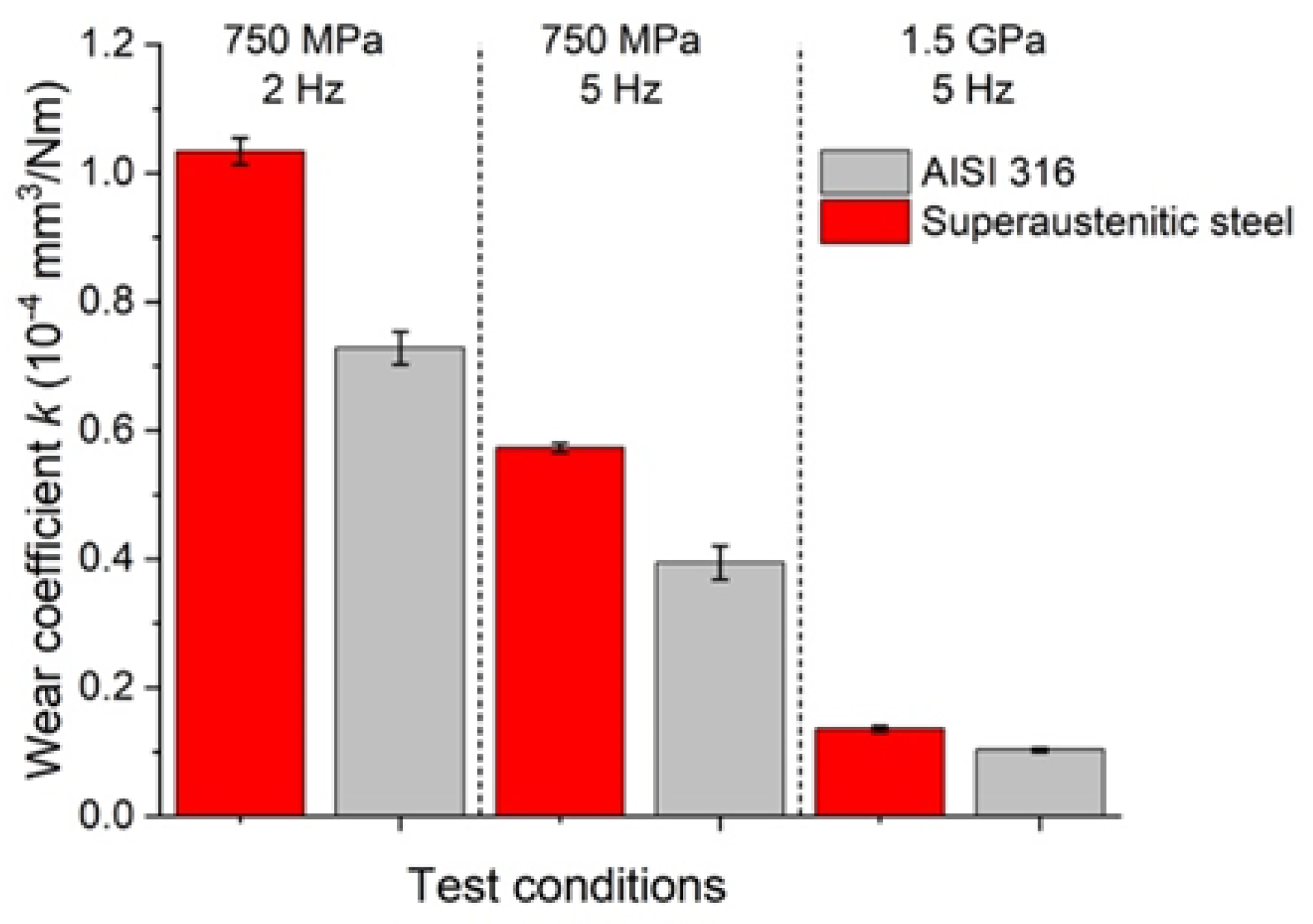
3.3. Tribocorrosion Behaviour

The open-circuit potential (OCP) trend depicted in Figure 3 reveals the typical behaviour of active–passive metals. During the initial phase, the potential stabilizes around a specific value. Notably, the superaustenitic steel exhibits a slightly more noble (positive) potential compared to the AISI 316L used as reference. The tribocorrosion behaviour is characterized by the interplay between mechanical wear and electrochemical processes. In particular, several key factors deserve attention, such as the passive film dynamics, since the continuous removal and reformation of the passive film lead to variations in surface chemistry and electrochemical activity [42]. The exposed bare metal typically shows a more anodic potential due to accelerated oxidation, while the surrounding passive areas maintain more cathodic potential, leading to the formation of a galvanic coupling and intensifying localized corrosion phenomena at the wear track [43]. The galvanic interaction between passive and active areas promotes a localized increase in corrosion rate in the active zone, which is further increased by the mechanical wear [44]. This synergy between mechanical and electrochemical effects makes tribocorrosion particularly detrimental for metal surfaces. At the onset of sliding, the OCP exhibited an anodic shift, indicating a transient movement toward more positive values. This shift reflects the initial exposure of the fresh metal surface due to passive film removal by mechanical wear [45]. The newly exposed surface undergoes rapid oxidation, temporarily increasing the anodic activity before stabilizing. This behaviour is typical in tribocorrosion environments, where the dynamic balance between passive film breakdown and reformation governs the electrochemical response during sliding [42,43,44,45]. During the abrasion process, the potential demonstrates irregular fluctuations.
The resulting potential reflects the interplay of two opposing processes. On the one hand, the mechanical wear action tends to remove the surface oxide film, exposing a fresh, unprotected surface to the electrolyte solution. Conversely, the corrosive environment and the tribological interaction (combined wear and friction) simultaneously promote the reformation of the passivating film on the exposed metal surface. When the rates of these opposing processes are comparable, the observed fluctuating potential trend is obtained. Upon termination of the wear action causing the initial breakdown, the passivating film can re-establish itself, leading to the potential to return towards an equilibrium value that is close to that observed at the end of the initial stabilization phase [46].
Both tested steels exhibited similar behaviours and comparable open-circuit potential (OCP) trends, as shown in Figure 3. However, variations in the potential during the sliding phase were observed for both materials. Notably, the potential became less noble (shifted towards negative values) as the severity of the sliding conditions increased. This trend can be attributed to the progressively greater abrasive action caused by higher applied loads and increased sliding frequencies [47]. These factors lead to more extensive damage to the passive film and hinder its ability to reform effectively with each pass of the counterbody. Interestingly, the superaustenitic steel displayed a greater sensitivity to the frequency than applied load, as evidenced by the more pronounced decrease in OCP with increasing frequencies compared to increasing loads. This suggests that under operational conditions, this material might perform better when subjected to increasing loads rather than sudden changes in sliding modes, since the latter scenario imposes greater damage on the protective passive film [45,48]. Furthermore, the noise level in the OCP data also increased with the severity of the test conditions. This behaviour reflects the cyclical process of damage and restoration of the passive layer during each pass of the counterbody on the steel surface [42,47,48,49,50]. At higher frequencies, the rapid removal of the passive layer outpaces its ability to regenerate. This effect is further exacerbated by increased applied loads.
The observed surface instability during tribocorrosion testing is attributed to the combined effects of mechanical abrasion by the counterbody and electrochemical oxidation in the saline environment [51,52,53]. Specifically, the Al2O3 counterbody imposes continuous sliding contact, mechanically disrupting the passive oxide film and producing fine wear debris. Concurrently, the 3.5 wt% NaCl solution facilitates electrochemical reactions on the exposed metal, leading to the oxidation of surface atoms and further weakening of the material. This synergy between mechanical and chemical degradation mechanisms accelerates surface damage, increases debris formation, and contributes to the fluctuating electrochemical response observed during testing [45,53].
The trends in the coefficient of friction (COF) were generally similar for both materials, with only minor variations being observed. At the lower load (750 MPa), the COF remained constant. However, a significant decrease in COF was observed at the higher load (1.5 GPa) (Figure 4). This high instability was likely due to the detachment of debris from the material surface, resulting from the combined abrasive action of the counterbody and the oxidative effects of the working environment. Detailed characterization of the wear scar geometry for each sample was performed using stylus profilometry. Additionally, the material volume loss after the tribocorrosion tests was estimated following the ASTM G133-02 standard [54]. The results of these analyses are presented in Figure 5.
Consistent with expectations, the wear scar profiles, as depicted in Figure 5, revealed progressively deeper traces on both tested steels as the severity of the test conditions increased. As summarized in Figure 6, the wear rate of the AISI 316L steel exhibited a slight advantage at the lower applied load (750 MPa). However, at the higher load (1.5 GPa), the wear scar profiles for both materials became nearly indistinguishable.
An examination of the worn surfaces via SEM revealed a dominant abrasive wear mechanism, characterized by plastic deformation and the generation of typical ploughing lines [47,48,51,52,53], as demonstrated in Figure 7. This observation suggests a mixed interaction between two-body wear (direct contact between the counterbody and the steel surface) and three-body wear (abrasive debris trapped within the contact zone). Interestingly, the superaustenitic steel exhibited a greater degree of surface damage compared to AISI 316L, as shown in Figure 8. This is evidenced by deeper and more prominent scratch marks, indicative of more pronounced plastic deformation and potential fatigue-related damage on the surface.
Abrasive wear arises from the shearing action that is exerted by hard asperities on a softer surface. This phenomenon can occur through two main mechanisms: two-body wear, involving direct contact between the counterbody and the material surface, and three-body wear, where abrasive particles and debris are trapped at the sliding interface [49,50,55,56,57,58]. In the present investigation, the abrasive particles responsible for three-body wear are likely the debris generated from the material surface due to the abrasive action of the ceramic counterpart.
Material removal occurs through various mechanisms, such as microcutting, microfractures, individual grain pull-outs, or accelerated fatigue caused by repeated plastic deformation [57]. The removed material forms wear debris, and the worn surface exhibits numerous notches, oriented in the direction of sliding. Below the abraded surface, a significant degree of plastic deformation is typically observed. This work hardening can lead to a decrease in the wear rate over time. When the worn material is ductile, as in the case of most metals, the cutting action is accompanied by repeated plastic deformations. The resulting wear debris originates from these fatigue phenomena. Along with these abrasive wear mechanisms is the potential for additional material loss due to corrosive wear. This process results from the chemical interaction between the worn material and a corrosive environment. Evidence of this combined effect is observed in the backscattered electron (BSE) images, which reveal the presence of oxidized areas within the wear scar.

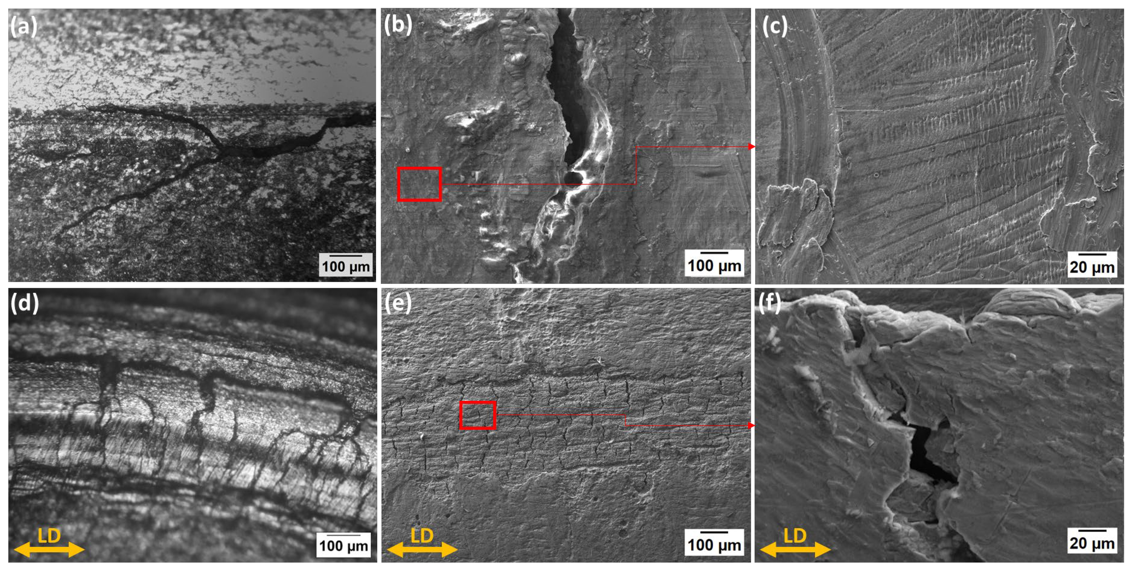
3.4. Stress Corrosion Cracking Analysis

A microscopic examination of the hybrid wires following immersion in boiling magnesium chloride solution for one hour revealed the influence of tensile loading on the SCC susceptibility, as summarized in Figure 9a,d. In the unstressed specimens, SCC was predominantly observed along the weld interface with the base metal in the longitudinal direction (parallel to the weld). In contrast, tensile loading resulted in additional crack formation in the transverse direction (perpendicular to the weld). Further analysis using SEM provided detailed insights into the mechanisms behind these observations (Figure 9b,c,e,f).
For the unstressed specimens, the SEM micrographs revealed selective dissolution of interdendritic regions on the weld surface. This preferential attack suggests the presence of less noble phases within these areas. Consistent with previous microstructural observations (Figure 1), the presence of delta ferrite in these interdendritic regions is highly likely. Decades of research have established that delta ferrite possesses lower corrosion resistance than the austenitic phase [59,60,61,62]. This difference in nobility leads to the formation of localized galvanic couples, promoting the selective dissolution of the interdendritic delta ferrite [63,64,65,66,67].
The formation of cracks in the specimens, even in the absence of an applied stress in this direction, can be attributed to two key factors. Firstly, the high radial residual stresses measured in this study (as discussed previously) likely played a significant role. These stresses act in a perpendicular direction to the observed longitudinal cracks. The presence of these tensile residual stresses can promote crack initiation and propagation along this direction.
Secondly, while the heat-affected zone (HAZ) in these wires was relatively narrow, the interface between the base metal and the weld region represents a zone of significant microstructural heterogeneity. Such heterogeneities can act as preferential sites for crack initiation. Furthermore, shrinkage during weld solidification is known to induce additional residual stresses, particularly at the weld–metal interface. These localized stresses can further contribute to crack formation in these regions [18,68,69,70,71,72]. The observation of cracks oriented perpendicular to the tensile loading direction in the loaded specimens highlights a critical concern for the hybrid wires under investigation. This finding suggests a high susceptibility to SCC initiation and propagation under combined tensile stress and corrosive environments. Future studies should explore mitigation strategies to address both the microstructural susceptibility (e.g., minimizing the delta ferrite content) and the management of residual stresses to enhance the overall performance and service life of these hybrid wires.

4. Discussion

This study delivers a comprehensive experimental assessment of a novel hybrid tubular system, designed for offshore and marine applications, consisting of a superaustenitic stainless steel (6Mo) outer shell encasing a pultruded CFRP core. The results from microstructural characterization, residual stress analysis, tribocorrosion evaluation, and SCC testing provide key insights into the behaviour and potential vulnerabilities of this hybrid structure under harsh service conditions.
The microstructural analysis revealed a strongly elongated grain structure in the cold-rolled steel and dendritic solidification within the weld fusion zone, common to TIG welding processes. Importantly, no clearly defined heat-affected zone (HAZ) was observed, which is likely due to the combined effect of the thin metal gauge and the high thermal conductivity of the internal CFRP core. This rapid heat dissipation appears to minimize HAZ development, potentially reducing the localized corrosion susceptibility that is often associated with thermal gradients and phase transformations in welded joints. However, SEM imaging highlighted the segregation of elements like Cr, Mo, and Si within the interdendritic regions. Such elemental heterogeneities are known to create electrochemical potential gradients, potentially serving as initiation sites for localized corrosion, especially in chloride-rich environments.
X-ray diffraction measurements revealed high residual stress levels, especially in the radial direction (up to 800 MPa), attributed to cold forming and thermal mismatch between the metallic shell and CFRP core during processing. These internal stresses can act synergistically with external loads and corrosive media to promote SCC. SCC testing using boiling MgCl2 demonstrated that even in the absence of externally applied stress, the hybrid wires exhibited cracking along the weld–base metal interface. These cracks followed the interdendritic paths, consistent with microstructural observations suggesting the presence of delta-ferrite, an electrochemically less noble phase prone to preferential dissolution. In U-bend samples under tensile loading, additional cracks appeared perpendicular to the loading direction, indicating a strong influence of both applied and residual stresses on crack nucleation and propagation. The localization of cracks at the fusion boundaries and interdendritic zones further supports the role of segregation and microstructural heterogeneity in facilitating SCC initiation.
These findings underline a critical design consideration: While the absence of a pronounced HAZ may enhance corrosion performance, the combined effects of residual stress, welding-induced segregation, and microstructural inhomogeneity still pose a substantial risk for SCC in these hybrid structures.
Furthermore, the tribocorrosion tests highlighted the complex interaction between mechanical wear and electrochemical degradation. Both the 6Mo and 316L steels demonstrated active–passive behaviour, with 6Mo showing slightly more noble OCP values. Under dynamic sliding conditions, however, passive film breakdown and regeneration led to fluctuating potentials. An increased sliding frequency had a more detrimental effect than load, with more pronounced drops in OCP and greater surface damage. This suggests that high-frequency wear may impair passive film recovery, leading to accelerated localized corrosion and mechanical degradation.
The SEM analysis of the wear tracks indicated a combination of two-body and three-body abrasive wear mechanisms, supported by ploughing marks, debris accumulation, and significant plastic deformation. In addition to mechanical wear, evidence of oxidative degradation within wear scars pointed to a strong contribution of tribo-oxidation processes. Interestingly, the 6Mo steel exhibited more extensive surface damage than 316L, especially under harsher test conditions, suggesting that the superior corrosion resistance of 6Mo under static conditions does not always translate directly to improved tribocorrosion resistance when dynamic wear is present.
The hybrid structure offers compelling advantages, particularly a significant weight reduction (~50–60%) without major sacrifices in strength or corrosion resistance. However, this study reveals that these benefits must be balanced against the introduction of new vulnerabilities, most notably microstructural segregation, residual stresses, and SCC susceptibility at the weld interfaces. The tribocorrosion and SCC data both underscore the importance of careful welding process control, alloy selection, and post-processing treatments (e.g., stress relief, surface passivation) to mitigate long-term degradation. In particular, the weld region emerges as a critical focal point for further optimization, especially in terms of reducing segregation and managing stress accumulation.
This investigation represents a significant first step in experimentally evaluating the corrosion and mechanical reliability of CFRP-6Mo hybrid wires. The findings point to a promising application space, particularly in offshore and energy sectors, but also call attention to critical process and material factors that must be addressed to ensure durability. Future work should explore approaches such as controlled cooling, improved weld filler materials, and alternative joining methods to reduce the formation of susceptible microstructures and minimize residual stress. Ultimately, this study lays the groundwork for the design of safer, longer-lasting hybrid wire systems for structurally demanding environments.

5. Conclusions

This study provides the first experimental assessment of tribocorrosion and SCC behaviour in a novel hybrid tubular wire composed of a 6Mo superaustenitic stainless steel shell and a CFRP core. The key findings are as follows:
The TIG welding process produced interdendritic segregation without a pronounced heat-affected zone due to effective heat dissipation by the CFRP core.
High residual stresses, particularly in the radial direction (~800 MPa), were identified as a major contributor to SCC susceptibility.
SCC initiated at the weld interface, driven by microstructural heterogeneity and residual stress, even in the absence of an applied load.
Tribocorrosion testing showed that 6Mo performed better than 316L under load but was more sensitive to the sliding frequency, leading to greater surface damage.
These results demonstrate the hybrid wire’s potential for offshore applications, while underscoring the need for process optimization to mitigate corrosion-related risks.

Author Contributions

Conceptualization, A.Y. and K.B.; methodology, A.Y., K.B. and L.P.; formal analysis, A.Y., F.V., V.Z. and L.P.; investigation, A.Y., F.V., V.Z. and L.P.; resources, K.B.; writing—original draft preparation, A.Y., V.Z. and F.V.; writing—review and editing, A.Y.; supervision, A.Y., K.B. and L.P.; project administration, K.B.; funding acquisition, K.B. All authors have read and agreed to the published version of the manuscript.

Funding

This research was co-funded by the European Union under the Research Fund for Coal and Steel (RFCS) Programme—RFCS CALL 2019, as part of the project titled “Fiber Reinforced Steel Wires for High-Performance Lightweight Ropes and Cables Operating in Demanding Scenarios” (Project No. 899299).

Data Availability Statement

The raw data required to reproduce these findings can be made available upon reasonable request.

Conflicts of Interest

The authors declare no conflict of intrest.

References

  1. Mouradi, H.; El Barkany, A.; El Biyaali, A. Steel wire ropes failure analysis: Experimental study. Eng. Fail. Anal. 2018, 91, 234–242. [Google Scholar] [CrossRef]
  2. Yang, Y.; Fahmy, M.F.; Guan, S.; Pan, Z.; Zhan, Y.; Zhao, T. Properties and applications of FRP cable on long-span cable-supported bridges: A review. Compos. Part B Eng. 2020, 190, 107934. [Google Scholar] [CrossRef]
  3. Wu, J.; Xian, G.; Li, H. A novel anchorage system for CFRP cable: Experimental and numerical investigation. Compos. Struct. 2018, 194, 555–563. [Google Scholar] [CrossRef]
  4. Noisternig, J.F. Carbon Fibre Composites as Stay Cables for Bridges. Appl. Compos. Mater. 2000, 7, 139–150. [Google Scholar] [CrossRef]
  5. Bambach, M.; Elchalakani, M.; Zhao, X. Composite steel–CFRP SHS tubes under axial impact. Compos. Struct. 2009, 87, 282–292. [Google Scholar] [CrossRef]
  6. Moy, S.S.J.; Bloodworth, A.G. Strengthening a steel bridge with CFRP composites. Proc. Inst. Civ. Eng.-Struct. Build. 2007, 160, 81–93. [Google Scholar] [CrossRef]
  7. Yao, Y.; Shi, P.; Qi, S.; Yan, C.; Chen, G.; Liu, D.; Zhu, Y.; Herrmann, A. Manufacturing and mechanical properties of steel-CFRP hybrid composites. J. Compos. Mater. 2020, 54, 3673–3682. Available online: https://journals.sagepub.com/doi/full/10.1177/0021998320918287?casa_token=NDSUSRT0Gt8AAAAA%3Aof9YsVpOhgTI_uephaoLH9_Sfdjx2XU6xJ0Mql8QranPFDQKkXtJmEMBjrNNYKF8UTfAvWcmcbqiWgI (accessed on 22 July 2024). [CrossRef]
  8. Xiong, W.; Cai, C.S.; Xiao, R.; Deng, L. Concept and analysis of stay cables with a CFRP and steel composite section. KSCE J. Civ. Eng. 2012, 16, 107–117. [Google Scholar] [CrossRef]
  9. Cai, H.; Aref, A.J. On the design and optimization of hybrid carbon fiber reinforced polymer-steel cable system for cable-stayed bridges. Compos. Part B Eng. 2015, 68, 146–152. [Google Scholar] [CrossRef]
  10. Bhandari, J.; Khan, F.; Abbassi, R.; Garaniya, V.; Ojeda, R. Modelling of pitting corrosion in marine and offshore steel structures—A technical review. J. Loss Prev. Process Ind. 2015, 37, 39–62. [Google Scholar] [CrossRef]
  11. Sunny, K.T.; Korra, N.N. A systematic review about welding of super austenitic stainless steel. Mater. Today Proc. 2021, 47, 4378–4381. [Google Scholar] [CrossRef]
  12. Gunasekaran, K.N.; Balamurugan, D.; Babin, M.; Raj, K.J.B.; Arun, S. Influence of Pitting Corrosion on TIG Welded Joints of AA2024 Aluminum Alloy Joints. J. Phys. Conf. Ser. 2021, 2115, 012052. [Google Scholar] [CrossRef]
  13. Dadfar, M.; Fathi, M.H.; Karimzadeh, F.; Dadfar, M.R.; Saatchi, A. Effect of TIG welding on corrosion behavior of 316L stainless steel. Mater. Lett. 2007, 61, 2343–2346. [Google Scholar] [CrossRef]
  14. Bilmes, P.D.; Llorente, C.L.; Saire Huamán, L.; Gassa, L.M.; Gervasi, C.A. Microstructure and pitting corrosion of 13CrNiMo weld metals. Corros. Sci. 2006, 48, 3261–3270. [Google Scholar] [CrossRef]
  15. Chaves, I.A.; Melchers, R.E. Pitting corrosion in pipeline steel weld zones. Corros. Sci. 2011, 53, 4026–4032. [Google Scholar] [CrossRef]
  16. Garcia, C.; de Tiedra, M.; Blanco, Y.; Martin, O.; Martin, F. Intergranular corrosion of welded joints of austenitic stainless steels studied by using an electrochemical minicell. Corros. Sci. 2008, 50, 2390–2397. [Google Scholar] [CrossRef]
  17. Kumar, M.V.; Balasubramanian, V.; Rajakumar, S.; Albert, S.K. Stress corrosion cracking behaviour of gas tungsten arc welded super austenitic stainless steel joints. Def. Technol. 2015, 11, 282–291. [Google Scholar] [CrossRef]
  18. Lu, B.T.; Chen, Z.K.; Luo, J.L.; Patchett, B.M.; Xu, Z.H. Pitting and stress corrosion cracking behavior in welded austenitic stainless steel. Electrochim. Acta 2005, 50, 1391–1403. [Google Scholar] [CrossRef]
  19. Yazdanpanah, A.; Franceschi, M.; Bergamo, G.; Bonesso, M.; Dabalà, M. On the exceptional stress corrosion cracking susceptibility of selective laser melted 316L stainless steel under the individual effect of surface residual stresses. Eng. Fail. Anal. 2022, 136, 106192. [Google Scholar] [CrossRef]
  20. Residual Stress Characterization of Welds Using X-Ray Diffraction Techniques|INIS, (n.d.). Available online: https://inis.iaea.org/search/search.aspx?orig_q=RN:28053342 (accessed on 22 July 2024).
  21. Yazdanpanah, A.; Pagot, G.; Franceschi, M.; Rebesan, P.; Venturin, M.; Botinha, J.; Gerhmann, B.; De Graeve, I.; Di Noto, V.; Revilla, R.I.; et al. Mechanism of alteration in passivity of additively manufactured Ni-Fe-Cr Alloy 718 caused by minor carbon variation. Electrochim. Acta 2024, 503, 144925. [Google Scholar] [CrossRef]
  22. ASTM G36-94(2018); Standard Practice for Evaluating Stress-Corrosion-Cracking Resistance of Metals and Alloys in a Boiling Magnesium Chloride Solution. ASTM: West Conshohocken, PA, USA, 2024.
  23. Mohammadzehi, S.; Mirzadeh, H. Cold unidirectional/cross-rolling of austenitic stainless steels: A review. Arch. Civ. Mech. Eng. 2022, 22, 129. [Google Scholar] [CrossRef]
  24. Kumar, B.; Singh, A.; Das, S.; Bhattacharya, D. Cold rolling texture in AISI 304 stainless steel. Mater. Sci. Eng. A 2004, 364, 132–139. [Google Scholar] [CrossRef]
  25. Chowdhury, S.G.; Das, S.; De, P. Cold rolling behaviour and textural evolution in AISI 316L austenitic stainless steel. Acta Mater. 2005, 53, 3951–3959. [Google Scholar] [CrossRef]
  26. Shaughnessy, B.M.; Eccleston, P.; Fereday, K.J.; Canfer, S.J.; Nørgaard-Nielsen, H.U.; Jessen, N.C. Thermal conductivity measurement below 40 K of the CFRP tubes for the Mid-Infrared Instrument mounting struts. Cryogenics 2007, 47, 348–352. [Google Scholar] [CrossRef]
  27. Bui, H.K.; Senghor, F.D.; Wasselynck, G.; Trichet, D.; Fouladgar, J.; Lee, K.; Berthiau, G. Characterization of Electrical Conductivity of Anisotropic CFRP Materials by Means of Induction Thermography Technique. IEEE Trans. Magn. 2018, 54, 1–4. [Google Scholar] [CrossRef]
  28. Adamczyk, W.P.; Pawlak, S.; Ostrowski, Z. Determination of thermal conductivity of CFRP composite materials using unconventional laser flash technique. Measurement 2018, 124, 147–155. [Google Scholar] [CrossRef]
  29. Hertzman, S.; Brolund, B.; Ferreira, P.J. An experimental and theoretical study of heat-affected zone austenite reformation in three duplex stainless steels. Metall. Mater. Trans. A 1997, 28, 277–285. [Google Scholar] [CrossRef]
  30. Wu, T.-H.; Wang, J.-J.; Li, H.-B.; Jiang, Z.-H.; Liu, C.-M.; Zhang, H.-Y. Effect of heat input on austenite microstructural evolution of simulated heat affected zone in 2205 duplex stainless steel. J. Iron Steel Res. Int. 2019, 26, 435–441. [Google Scholar] [CrossRef]
  31. Hamza, S.; Boumerzoug, Z.; Boumerzoug, E.R.; Delaunois, F. Simulated heat affected zone in welded stainless steel 304l. Acta Metall. Slovaca 2019, 25, 142–149. [Google Scholar] [CrossRef]
  32. Shankar, V.; Gill, T.P.S.; Mannan, S.L.; Sundaresan, S. Fusion zone and heat affected zone cracking susceptibility of stabilised austenitic stainless steels. Sci. Technol. Weld. Join. 1998, 3, 17–24. [Google Scholar] [CrossRef]
  33. Takalo, T.; Suutala, N.; Moisio, T. Austenitic solidification mode in austenitic stainless steel welds. Metall. Trans. A 1979, 10, 1173–1181. [Google Scholar] [CrossRef]
  34. Hänninen, H.; Minni, E. On grain boundary segregation in austenitic stainless steels. Metall. Trans. A 1982, 13, 2281–2285. [Google Scholar] [CrossRef]
  35. Suutala, N.; Takalo, T.; Moisio, T. Ferritic-austenitic solidification mode in austenitic stainless steel welds. Metall. Trans. A 1980, 11, 717–725. [Google Scholar] [CrossRef]
  36. Shankar, V.; Gill, T.P.S.; Mannan, S.L.; Sundaresan, S. Solidification cracking in austenitic stainless steel welds. Sadhana 2003, 28, 359–382. [Google Scholar] [CrossRef]
  37. Ramirez–Ledesma, A.L.; Acosta–Vargas, L.A.; Juarez–Islas, J.A. Suppression of interdendritic segregation during welding of a 347 austenitic stainless steel pipe reactors. Eng. Fail. Anal. 2020, 114, 104589. [Google Scholar] [CrossRef]
  38. Gasparrini, C.; Douglas, J.; Yazdanpanah, A.; Stroud, R.; Divitini, G.; Dabalà, M.; Scatigno, G.; Pedrazzini, S.; Wenman, M.; Badocco, D.; et al. Corrosion of 316L exposed to highly concentrated borated water used as shield in nuclear fusion experimental reactors cooling circuits. Corros. Sci. 2024, 230, 111902. [Google Scholar] [CrossRef]
  39. Yazdanpanah, A.; Revilla, R.I.; Franceschi, M.; Fabrizi, A.; Khademzadeh, S.; Khodabakhshi, M.; De Graeve, I.; Dabalà, M. Unveiling the impact of laser power variations on microstructure, corrosion, and stress-assisted surface crack initiation in laser powder bed fusion-processed Ni-Fe-Cr alloy 718. Electrochim. Acta 2024, 476, 143723. [Google Scholar] [CrossRef]
  40. Yazdanpanah, A.; Franceschi, M.; Rebesan, P.; Dabalà, M. Correlation of Lack of Fusion Pores with Stress Corrosion Cracking Susceptibility of L-PBF 316L: Effect of Surface Residual Stresses. Materials 2022, 15, 7151. [Google Scholar] [CrossRef]
  41. Yazdanpanah, A.; Biglari, F.R.; Arezoodar, A.F.; Dabalà, M. Role of grinding induced surface residual stress on probability of stress corrosion cracks initiation in 316L austenitic stainless steel in 3.5% sodium chloride aqueous solution. Corros. Eng. Sci. Technol. 2021, 56, 81–92. [Google Scholar] [CrossRef]
  42. Tribocorrosion of Stainless Steels (Review)-ProQuest. Available online: https://www.proquest.com/openview/5091c2defeb64df380e17232d0bfe0cb/1?cbl=2034508&pq-origsite=gscholar (accessed on 19 May 2025).
  43. Wood, R.J.K. Marine wear and tribocorrosion. Wear 2017, 376–377, 893–910. [Google Scholar] [CrossRef]
  44. López-Ortega, A.; Arana, J.L.; Bayón, R. Tribocorrosion of Passive Materials: A Review on Test Procedures and Standards. Int. J. Corros. 2018, 2018, 7345346. [Google Scholar] [CrossRef]
  45. Landolt, D.; Mischler, S. Tribocorrosion of Passive Metals and Coatings; Elsevier: Amsterdam, The Netherlands, 2011. [Google Scholar]
  46. Mischler, S.; Debaud, S.; Landolt, D. Wear-Accelerated Corrosion of Passive Metals in Tribocorrosion Systems. J. Electrochem. Soc. 1998, 145, 750. [Google Scholar] [CrossRef]
  47. Landolt, D. Passivity Issues in Tribocorrosion. In Passivation of Metals and Semiconductors, and Properties of Thin Oxide Layers; Marcus, P., Maurice, V., Eds.; Elsevier Science: Amsterdam, The Netherlands, 2006; pp. 477–487. [Google Scholar] [CrossRef]
  48. von der Ohe, C.B.; Johnsen, R.; Espallargas, N. Modeling the multi-degradation mechanisms of combined tribocorrosion interacting with static and cyclic loaded surfaces of passive metals exposed to seawater. Wear 2010, 269, 607–616. [Google Scholar] [CrossRef]
  49. Pintaude, G.; Sinatora, A.; Albertin, E. A review on abrasive wear mechanisms of metallic materials. In Proceedings of the Abrasion Wear Resistant Alloyed White Cast Iron for Rolling and Pulverizing Mills, Sao Paulo, Brazil, 14–17 August 2005. [Google Scholar] [CrossRef]
  50. Sin, H.; Saka, N.; Suh, N.P. Abrasive wear mechanisms and the grit size effect. Wear 1979, 55, 163–190. [Google Scholar] [CrossRef]
  51. Huttunen-Saarivirta, E.; Kilpi, L.; Hakala, T.J.; Carpen, L.; Ronkainen, H. Tribocorrosion study of martensitic and austenitic stainless steels in 0.01 M NaCl solution. Tribol. Int. 2016, 95, 358–371. [Google Scholar] [CrossRef]
  52. Zhang, Y.; Wang, J.-Z.; Yin, X.-Y.; Yan, F.-Y. Tribocorrosion behaviour of 304 stainless steel in different corrosive solutions. Mater. Corros. 2016, 67, 769–777. [Google Scholar] [CrossRef]
  53. Liu, Z.; Liu, E.; Du, S.; Zhang, J.; Wang, L.; Du, H.; Cai, H. Tribocorrosion Behavior of Typical Austenitic, Martensitic, and Ferritic Stainless Steels in 3.5% NaCl Solution. J. Mater. Eng. Perform. 2021, 30, 6284–6296. [Google Scholar] [CrossRef]
  54. ASTM G133-02; Standard Test Method for Linearly Reciprocating Ball-on-Flat Sliding Wear. ASTM: West Conshohocken, PA, USA, 2017.
  55. Williams, J.A.; Hyncica, A.M. Mechanisms of abrasive wear in lubricated contacts. Wear 1992, 152, 57–74. [Google Scholar] [CrossRef]
  56. Hokkirigawa, K.; Kato, K.; Li, Z.Z. The effect of hardness on the transition of the abrasive wear mechanism of steels. Wear 1988, 123, 241–251. [Google Scholar] [CrossRef]
  57. Murray, M.J.; Mutton, P.J.; Watson, J.D. Abrasive Wear Mechanisms in Steels. J. Lubr. Technol. 1982, 104, 9–16. [Google Scholar] [CrossRef]
  58. Kayaba, T.; Hokkirigawa, K.; Kato, K. Analysis of the abrasive wear mechanism by successive observations of wear processes in a scanning electron microscope. Wear 1986, 110, 419–430. [Google Scholar] [CrossRef]
  59. Wegrzyn, T. Delta ferrite in stainless steel weld metals. Weld. Int. 1992, 6, 690–694. [Google Scholar] [CrossRef]
  60. Sui, G.; Charles, E.A.; Congleton, J. The effect of delta-ferrite content on the stress corrosion cracking of austenitic stainless steels in a sulphate solution. Corros. Sci. 1996, 38, 687–703. [Google Scholar] [CrossRef]
  61. Kim, S.Y.; Kwon, H.S.; Kim, H.S. Effect of Delta Ferrite on Corrosion Resistance of Type 316L Stainless Steel in Acidic Chloride Solution by Micro-Droplet Cell. Solid State Phenom. 2007, 124–126, 1533–1536. [Google Scholar] [CrossRef]
  62. Osoba, L.O.; Elemuren, R.A.; Ekpe, I.C. Influence of delta ferrite on corrosion susceptibility of AISI 304 austenitic stainless steel. Cogent Eng. 2016, 3, 1150546. [Google Scholar] [CrossRef]
  63. Yazdanpanah, A.; De Pietri, A.; Ben Hjal, A.; Khodabakhshi, M.; Biasiolo, L.; Dabalà, M. Electrochemical and localized corrosion characteristics of kolsterised and DLC-coated 316LVM stainless steel for biomedical applications. Appl. Surf. Sci. 2025, 693, 162808. [Google Scholar] [CrossRef]
  64. Yazdanpanah, A.; Revilla, R.I.; Franceschi, M.; Pagot, G.; Khodabakhshi, M.; De Graeve, I.; Di Noto, V.; Dabalà, M.; Lozano-Perez, S. Exploring the mechanism of stress-induced passive layer degradation in additively manufactured Ni-Fe-Cr-based alloy 718. Corros. Sci. 2024, 241, 112523. [Google Scholar] [CrossRef]
  65. Kim, S.H.; Moon, H.K.; Kang, T.; Lee, C.S. Dissolution kinetics of delta ferrite in AISI 304 stainless steel produced by strip casting process. Mater. Sci. Eng. A 2003, 356, 390–398. [Google Scholar] [CrossRef]
  66. Pujar, M.G.; Dayal, R.K.; Gill, T.P.S.; Malhotra, S.N. Role of Delta-Ferrite in the Dissolution of Passive Films on the Austenitic Stainless-Steel Weld Metals. J. Mater. Sci. Lett. 1999, 18, 823–826. [Google Scholar] [CrossRef]
  67. Ben Rhouma, A.; Amadou, T.; Sidhom, H.; Braham, C. Correlation between microstructure and intergranular corrosion behavior of low delta-ferrite content AISI 316L aged in the range 550–700 °C. J. Alloys Compd. 2017, 708, 871–886. [Google Scholar] [CrossRef]
  68. Krivonosova, E.A. A Review of Stress Corrosion Cracking of Welded Stainless Steels. Open Access Libr. J. 2018, 5, 1. [Google Scholar] [CrossRef]
  69. Li, G.F.; Congleton, J. Stress corrosion cracking of a low alloy steel to stainless steel transition weld in PWR primary waters at 292°C. Corros. Sci. 2000, 42, 1005–1021. [Google Scholar] [CrossRef]
  70. Lucas, T.; Ballinger, R.G.; Hanninen, H.; Saukkonen, T. Effect of Thermal Aging on SCC, Material Properties and Fracture Toughness of Stainless Steel Weld Metals. In Proceedings of the 15th International Conference on Environmental Degradation of Materials in Nuclear Power Systems—Water Reactors, Colorado Springs, CO, USA, 7–11 August 2011; Busby, J.T., Ilevbare, G., Andresen, P.L., Eds.; Springer International Publishing: Cham, Switzerland, 2016; pp. 883–905. [Google Scholar] [CrossRef]
  71. Yazdanpanah, A.; Capuzzo, N.; Khodabakhshi, M.; Dabalà, M. Evaluation of stress-assisted corrosion performance of L-PBF processed Ti6Al4V: A microcapillary electrochemical approach. Eng. Fail. Anal. 2024, 166, 108891. [Google Scholar] [CrossRef]
  72. Stress Corrosion Cracking of Type 304 Stainless Steel Weldments in the Active State|CORROSION|Association for Materials Protection and Performance. Available online: https://content.ampp.org/corrosion/article-abstract/50/3/171/5725/Stress-Corrosion-Cracking-of-Type-304-Stainless?redirectedFrom=fulltext (accessed on 19 May 2025).
Figure 1. Backscattered SEM microstructural analysis of the hybrid tubes. (a) The overall fusion zone and base metal, (b) based metal, and (c) fusion zone.
Cmd 06 00022 g001
Figure 2. SEM analysis of the TIG-welded (a) HAZ and (b) fusion zone. The red dashed line is showing different zones observed.
Cmd 06 00022 g002
Figure 3. OCP decay plots for the tribocorrosion tests performed on (a) 6Mo steel and (b) on AISI316 steel.
Cmd 06 00022 g003
Figure 4. Friction coefficient plots for the tribocorrosion tests performed on (a) 6Mo steel and (b) on AISI316 steel.
Cmd 06 00022 g004
Figure 5. Wear depth analysis of the tribocorrosion tests performed on (a) 6Mo steel and (b) on AISI316 steel.
Cmd 06 00022 g005
Figure 6. Wear rate calculated for the different samples under the various analysed conditions.
Cmd 06 00022 g006
Figure 7. SEM (a) secondary image, (b) backscattered image of the wear tracks in the 6Mo steel (750 MPa, 2 Hz), (c) secondary image, and (d) backscattered image of the wear tracks in the 6Mo steel (750 MPa, 2 Hz).
Cmd 06 00022 g007
Figure 8. SEM (a) secondary image, (b) backscattered image of the wear tracks in the 316L stainless steel (750 MPa, 2 Hz), (c) secondary image, and (d) backscattered image of the wear tracks in the 316L stainless steel (750 MPa, 2 Hz).
Cmd 06 00022 g008
Figure 9. SCC morphology of (ac) without tensile stress in as-received state and (df) for the U-bend specimens, with LD denoting the bending direction. The higher magnification image of the red squared region is shown in the other figure accordingly.
Cmd 06 00022 g009
Table 1. Chemical composition of the X1CrNiMoCuN20-18-7 superaustenitic stainless steel used for the production of hybrid wires.
ElementCSiMnCrMoNiN
wt. %0.020.180.6520.306.3017.800.20
Disclaimer/Publisher’s Note: The statements, opinions and data contained in all publications are solely those of the individual author(s) and contributor(s) and not of MDPI and/or the editor(s). MDPI and/or the editor(s) disclaim responsibility for any injury to people or property resulting from any ideas, methods, instructions or products referred to in the content.

