
Forensic Investigation of Stainless Steel 316 Hydrogen-Membrane and Ammonia-Cracking Reactors Through Mechanical Testing

 ,
,  , , and
Abstract
1. Introduction
- Hydrogen embrittlement, when dissolved hydrogen within the metal causes a loss of ductility, which occurs at low temperature < 100 °C.
- Hydrogen stress cracking, when applied stress drives the diffusion of atomic hydrogen to cause localized embrittlement and cracking. This occurs in the absence of a corrosion process, i.e., when the material is polarized cathodically. When a corrosion reaction is present, i.e., the material is anodically polarized, cracking localized embrittlement/pits/inclusions is referred to as hydrogen stress corrosion cracking.
- Hydrogen blistering, through which hydrogen diffuses into the metal and accumulates at voids or inclusions to form subsurface planar cavities. The atomic hydrogen reforms into H2 gas and creates localized gas pressure/stress.
- Hydrogen-induced cracking, when cracks form to connect hydrogen blisters.
- Metal hydride embrittlement, when the diffusion of atomic hydrogen leads to the formation of brittle metal hydride phases in the material.
- High-temperature hydrogen attack, when atomic hydrogen reacts with carbides, sometimes forming methane in the steel and leading to decarburization and internal fissuring.
2. Materials and Methods
2.1. Materials
- HM reactor used for hydrogen separation. The tube was 25.4 mm (1”) in diameter and 1.2 m long, with 1.8 mm wall thickness (Figure 1b). The inner surface of the tube was exposed to 100% H2 atmosphere (1 bar) at 320–350 °C for ~100 h. The outer surface was exposed to air (1 bar) at 350–360 °C.
- AC reactor: 25.4 mm (1”) diameter pipe, 1.5 m long, with 6.0 mm wall thickness (Figure 1c). The inner surface of the pipe was exposed to a H2 + N2 + NH3 atmosphere (H2 (vol%) ~70%, NH3 (vol%) ~10%, P = 5–6 bar), at 500–520 °C for ~1000 h. The outer surface was exposed to air (1 bar) at 450–500 °C.
2.2. Mechanical Testing and Analysis
2.3. Microstructural Analysis
3. Results and Discussion
3.1. Tensile Tests
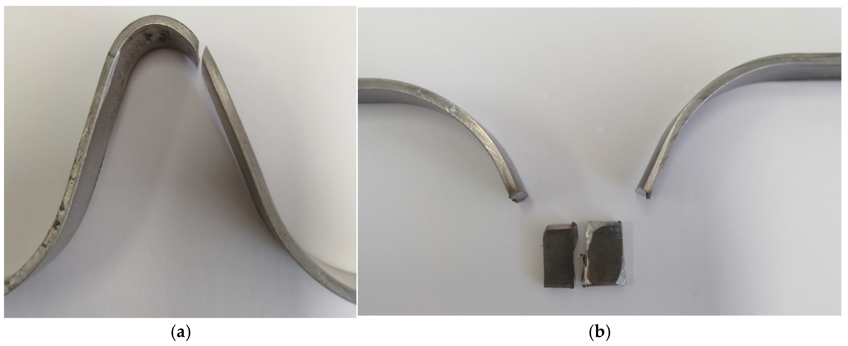
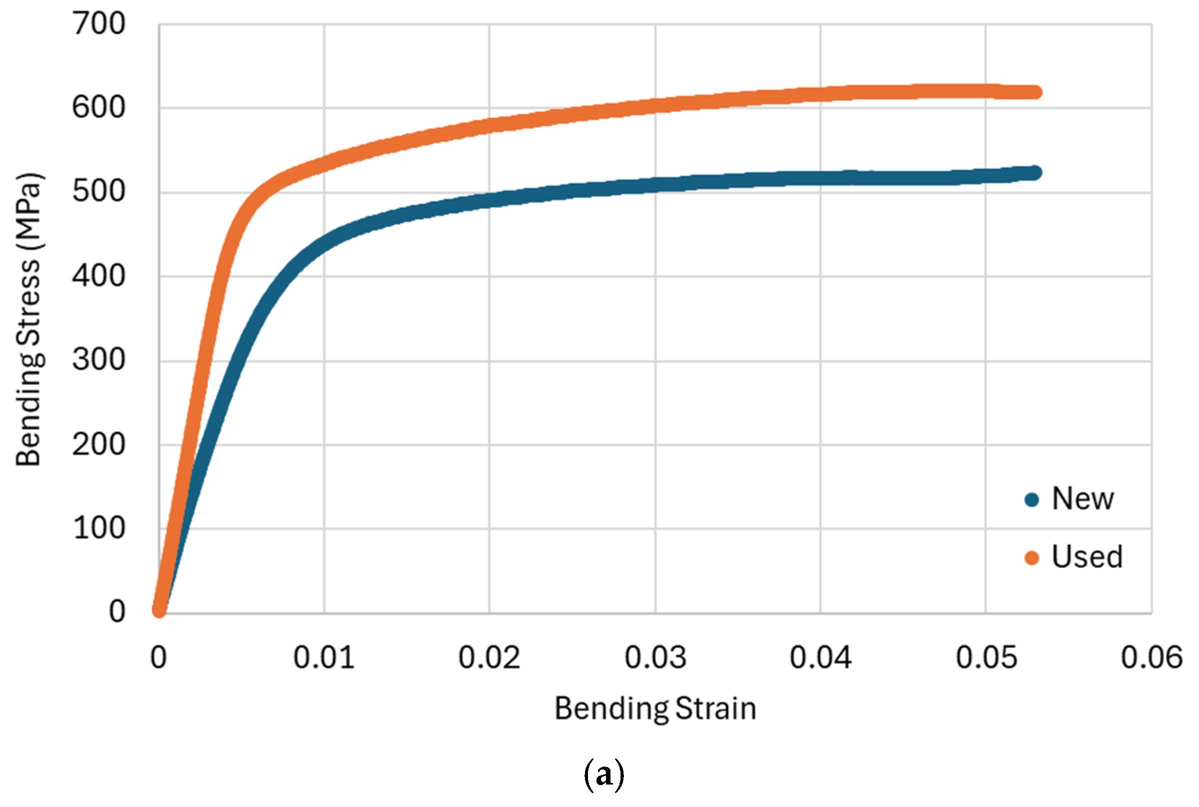
3.2. Stretch-Bend Tests
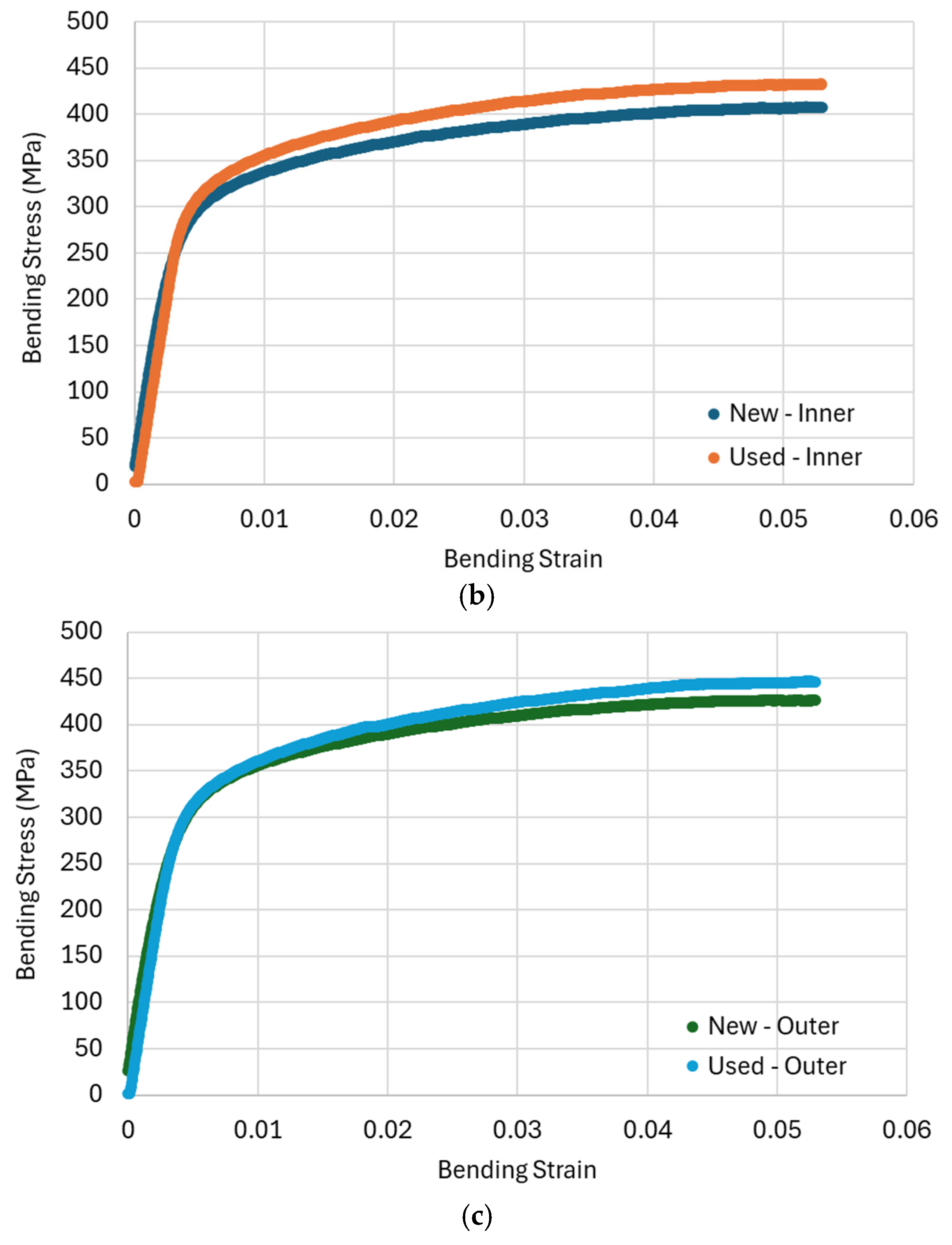
3.3. Bend Tests
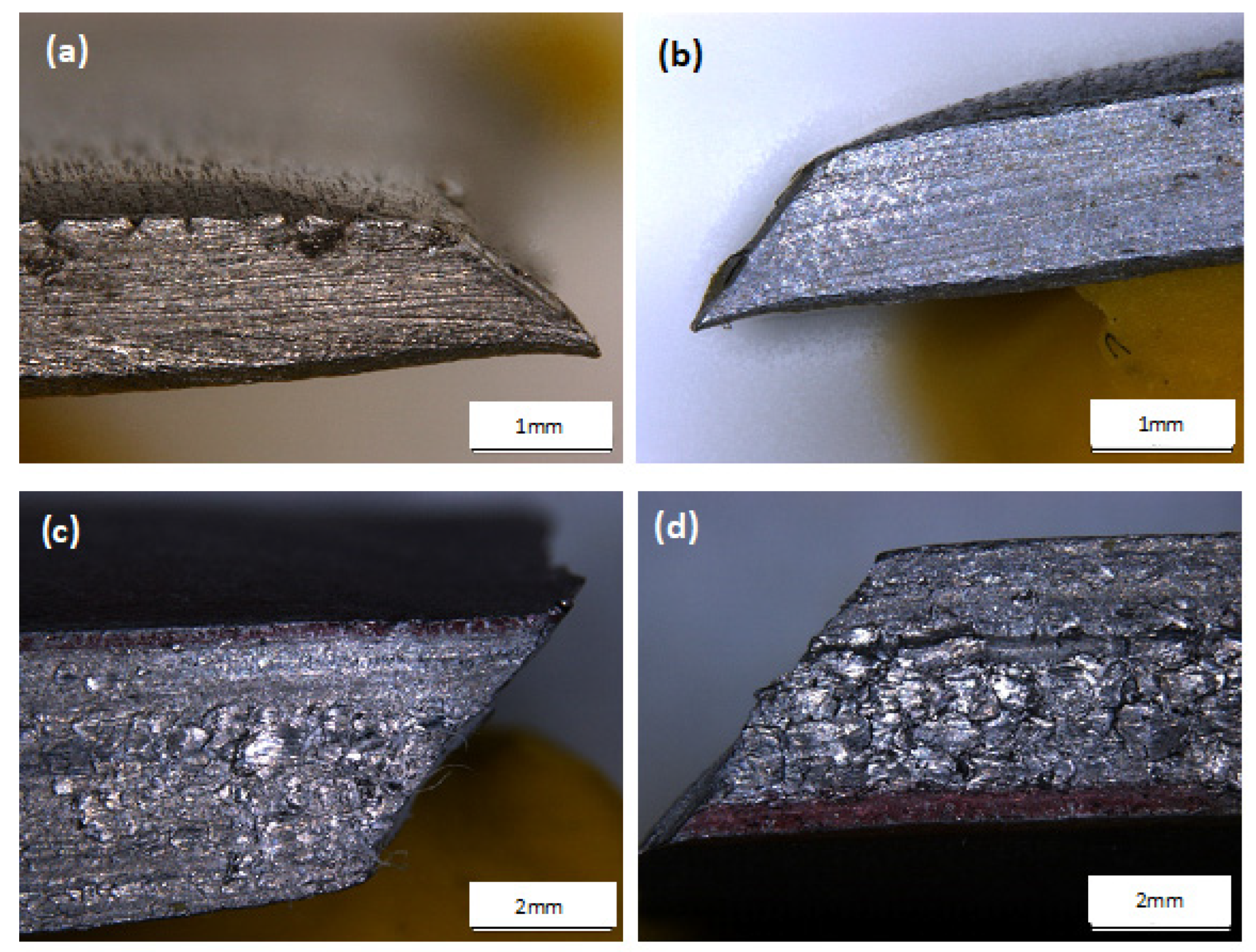
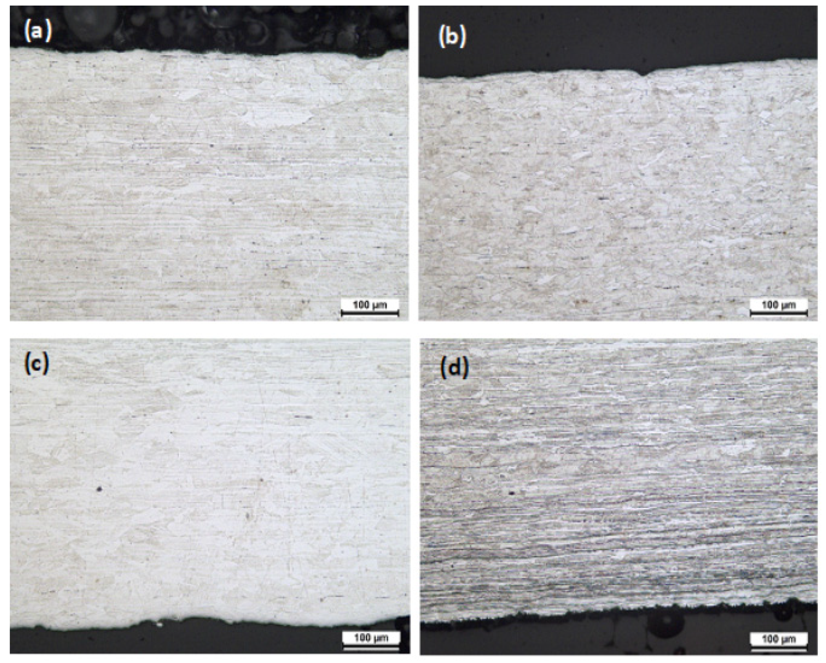
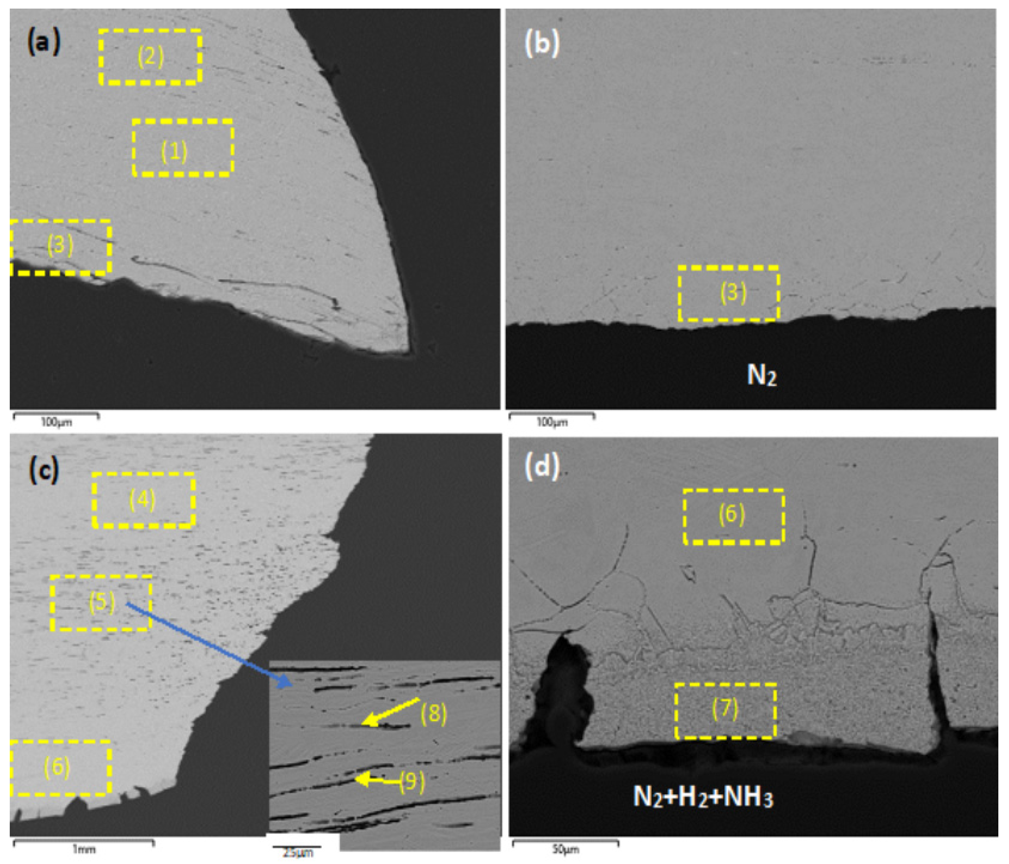
3.4. Microstructure
4. Conclusions
- More investigation is needed into how hydrogen interacts with metallic materials and their strengthening mechanisms under in-service conditions. The effect of heat treatment resulting from in-service conditions needs to be accounted for when assessing the impact of hydrogen embrittlement. The potential of stress relaxation caused by hydrogen and its impact on grain morphology also needs more understanding.
- Bend testing provides more pronounced results on the mechanical properties of an exposed material, as the loading conditions target surface damage. Bend testing may be a more informative test than tensile testing for forensic investigation.
Author Contributions
Funding
Data Availability Statement
Acknowledgments
Conflicts of Interest
Abbreviations
| HM | hydrogen membrane |
| AC | ammonia cracking |
| SBT | stretch–bend test |
| EDM | electrical discharge machining |
| SEM | scanning electron microscope |
| EDS | energy-dispersive spectroscopy |
References
- Hassan, Q.; Algburi, S.; Sameen, A.Z.; Salman, H.M.; Jaszczur, M. Green hydrogen: A pathway to a sustainable energy future. Int. J. Hydrogen Energy 2024, 50, 310–333. [Google Scholar] [CrossRef]
- Ishaq, H.; Dincer, I.; Crawford, C. A review on hydrogen production and utilization: Challenges and opportunities. Int. J. Hydrogen Energy 2022, 47, 26238–26264. [Google Scholar] [CrossRef]
- Lynch, S. Hydrogen embrittlement phenomena and mechanisms. Corros. Rev. 2012, 30, 105–123. [Google Scholar] [CrossRef]
- Dietzel, W.; Atrens, A.; Barnoush, A. 8—Mechanics of Modern Test Methods and Quantitative-Accelerated Testing for Hydrogen Embrittlement. In Gaseous Hydrogen Embrittlement of Materials in Energy Technologies; Gangloff, R.P., Somerday, B.P., Eds.; Woodhead Publishing: Sawston, UK, 2012; pp. 237–273. [Google Scholar]
- Djukic, M.B.; Bakic, G.M.; Zeravcic, V.S.; Sedmak, A.; Rajicic, B. Hydrogen embrittlement of industrial components: Prediction, prevention, and models. Corrosion 2016, 72, 943–961. [Google Scholar] [CrossRef] [PubMed]
- Flint, P.S. The Diffusion of Hydrogen Through Materials on Construction; Knolls Atomic Power Lab.: Niskatuna, NY, USA, 1951. [Google Scholar]
- Zhang, Y.H. Review of the effect of hydrogen gas on fatigue performance of steels. In Offshore Mechanics and Arctic Engineering; Granta Park, Great Abington: Cambridge, UK, 2010. [Google Scholar]
- Langley, R.A. Hydrogen trapping, diffusion and recombination in austenitic stainless steels. J. Nucl. Mater. 1984, 128–129, 622–628. [Google Scholar] [CrossRef]
- Oikawa, H.; Iijima, Y. Diffusion behaviour of creep-resistant steels. In Creep-Resistant Steels; Woodhead Publishing Limited: Cambridge, UK, 2008; pp. 241–264. [Google Scholar]
- Rawls, G.; Adams, T.; Newhouse, N. Hydrogen production and containment. In Gaseous Hydrogen Embrittlement of Materials in Energy Technology; Woodhead Publishing Ltd.: Sawston, UK, 2012; pp. 3–50. [Google Scholar]
- Takazaki, D.; Tsuchiyama, T.; Komoda, R.; Dadfarnia, M.; Somerday, B.P.; Sofronis, P.; Kubota, M. Effect of Hydrogen on Creep Properties of SUS304 Austenitic Stainless Steel. Corrosion 2021, 77, 256–265. [Google Scholar] [CrossRef] [PubMed]
- Kubota, M.; Takazaki, D.; Komoda, R.; Wada, K.; Tsuchiyama, T.; Dadfarnia, M.; Somerday, B.P.; Sofronis, P. Effect of Hydrogen on Creep Properties; Springer International Publishing: Cham, Switzerland, 2022; pp. 1541–1548. [Google Scholar]
- Tien, C.W.; Altstetter, C.J. Hydrogen-enhanced plasticity of 310S stainless steel. Mater. Chem. Phys. 1993, 35, 58–63. [Google Scholar] [CrossRef]
- He, J.; Han, G.; Fukuyama, S.; Yokogawa, K.; Kimura, A. Effect of hydrogen on dynamic precipitation of carbide in type 304 stainless steel during creep process. Acta Mater. 1997, 45, 3377–3388. [Google Scholar] [CrossRef]
- Dolan, M.D.; Viano, D.M.; Langley, M.J.; Lamb, K.E. Tubular vanadium membranes for hydrogen purification. J. Membr. Sci. 2018, 549, 306–311. [Google Scholar] [CrossRef]
- Lamb, K.E.; Viano, D.M.; Langley, M.J.; Hla, S.S.; Dolan, M.D. High-purity H2 produced from NH3 via a ruthenium-based decomposition catalyst and vanadium-based membrane. Ind. Eng. Chem. Res. 2018, 57, 7811–7816. [Google Scholar] [CrossRef]
- Weiss, B.; Stickler, R. Phase instabilities during high temperature exposure of 316 austenitic stainless steel. Metall. Trans. 1972, 3, 851–866. [Google Scholar] [CrossRef]
- ASTM A370; Standard Test Methods and Definitions for Mechanical Testing of Steel Product. ASTM: West Conshohocken, PA, USA, 2022.
- Tu, S.-T.; Zhang, K.; Bai, Y.; Tan, J.-P.; Deng, G.-J. Effect of stress regime-dependent creep behaviour on measurement of creep strain rate based on small specimen techniques. Fatigue Fract. Eng. Mater. Struct. 2019, 42, 187–196. [Google Scholar] [CrossRef]
- Yu, H.-Y.; Zhou, G.-Y. A new method to determine the beam bending creep critical displacement of three-point bending specimen with fixed constraints. Int. J. Mech. Sci. 2019, 161–162, 105045. [Google Scholar] [CrossRef]
- ASTM E290-14; Standard Test Methods for Bend Testing of Material for Ductility. ASTM: West Conshohocken, PA, USA, 2022.
- Bansal, A.K. Stretch Bend Testing of High Strength Low Alloy Sheet Steel. MS. Thesis, McMaster University, Hamilton, ON, Canada, 1977. [Google Scholar]
- Ghermaoui, I.M.A.; Oudriss, A.; Metsue, A.; Milet, R.; Madani, K.; Feaugas, X. Multiscale analysis of hydrogen-induced softening in f.c.c. nickel single crystals oriented for multiple-slips: Elastic screening effect. Sci. Rep. 2019, 9, 13042. [Google Scholar] [CrossRef] [PubMed]
- Ogawa, Y.; Hosoi, H.; Tsuzaki, K.; Redarce, T.; Takakuwa, O.; Matsunaga, H. Hydrogen, as an alloying element, enables a greater strength-ductility balance in an Fe-Cr-Ni-based, stable austenitic stainless steel. Acta Mater. 2020, 199, 181–192. [Google Scholar] [CrossRef]
- Turnbull, A.; Zhou, S. Residual stress relaxation in shot peened high strength low alloy steel and its implications for hydrogen assisted cracking. Mater. Sci. Technol. 2010, 26, 824–832. [Google Scholar] [CrossRef]
- Tien, J.-H.; Reger, M.; Johnson, D.R.; Bahr, D.F. Hydrogen charging can relax compressive residual stresses caused by shot peening. Int. J. Hydrogen Energy, 2024; in press. [Google Scholar] [CrossRef]
- Starostin, M.; Grinberg Dana, A.; Dinner, O.; Shter, G.E.; Grader, G.S. High-temperature corrosion of stainless steels and Ni alloys during combustion of urea–ammonium nitrate (UAN) fuel. Oxid. Met. 2017, 87, 39–56. [Google Scholar] [CrossRef]
- Martin, M.L.; Pundt, A.; Kirchheim, R. Hydrogen-induced accelerated grain growth in vanadium. Acta Mater. 2018, 155, 262–267. [Google Scholar] [CrossRef]
- Li, T.; Zheng, J.; Chen, Z. Description of full-range strain hardening behavior of steels. Springerplus 2016, 5, 1316. [Google Scholar] [CrossRef] [PubMed]


| Sample | Young’s Modulus (GPa) | Elastic Limit (MPa) | Ultimate Tensile Strength (MPa) | Strain at Failure (%) |
|---|---|---|---|---|
| HM new | 730 | 415 | 659 | 42 |
| HM used | 522 | 320 | 545 | 36 |
| AC new as-received | 169 | 182 | 644 | 88 |
| AC new heat-treated | 189 | 193 | 619 | 91 |
| AC used | 138 | 167 | 510 | 75 |
| Sample | Maximum Load, kN | Displacement at Maximum Load, mm |
|---|---|---|
| Displacement at 1 mm/min | ||
| New | 23.46–24.18 | 33.41–34.16 |
| Used | 18.15–20.21 | 25.2–33.81 |
| Displacement at 0.1 mm/min | ||
| New | 16.84 | 31.09 |
| Used | 12.96 | 21.96 |
| Sample | Flexural Modulus (GPa) | Elastic Limit (MPa) | Stress at 5% Strain (MPa) |
|---|---|---|---|
| HM new | 68.9 ± 1.5 | 211.1 ± 4.6 | 519.4 ± 11.4 |
| HM used | 108.5 ± 2.4 | 361 ± 7.6 | 620.4 ± 12.9 |
| AC new inner | 102.9 ± 1.9 | 179.6 ± 3.4 | 406.5 ± 7.7 |
| AC used inner | 73.7 ± 1.5 | 244.4 ± 5.1 | 431.5 ± 8.8 |
| AC new outer | 105.7 ± 2.1 | 180.5 ± 3.6 | 426.8 ± 8.5 |
| AC used outer | 79.9 ± 1.8 | 207.4 ± 4.5 | 445.4 ± 9.2 |
| Sample Identification | Fe | Cr | Ni | Mo | Mn | Si | N |
|---|---|---|---|---|---|---|---|
| Composition of new heat-treated SS316 | 69 | 17 | 10 | 2 | 2 | <1 | <1 |
| (1) New heat-treated, mid-wall | 69 | 17 | 10 | 2 | 2 | <1 | <1 |
| (2) New heat-treated, external surface | 69 | 17 | 10 | 2 | 1 | <1 | <1 |
| (3) New heat-treated, internal surface | 69 | 16 | 10 | 2 | 2 | <1 | <1 |
| (4) Used, outer surface | 69 | 18 | 10 | 2 | 2 | <1 | <1 |
| (5) Used ACR, mid-wall | 69 | 17 | 10 | 2 | 2 | <1 | <1 |
| (6) Used ACR, inner subsurface | 69 | 18 | 10 | 2 | 2 | <1 | <1 |
| (7) Used ACR, inner surface | 66 | 15 | 10 | 1 | 2 | <1 | 4 |
| (8) Used ACR, grain boundary void | 68 | 17 | 10 | 2 | 1 | <1 | <1 |
| (9) Used ACR, grain boundary void | 69 | 16 | 10 | 2 | 2 | <1 | <1 |
Disclaimer/Publisher’s Note: The statements, opinions and data contained in all publications are solely those of the individual author(s) and contributor(s) and not of MDPI and/or the editor(s). MDPI and/or the editor(s) disclaim responsibility for any injury to people or property resulting from any ideas, methods, instructions or products referred to in the content. |
© 2025 by the authors. Licensee MDPI, Basel, Switzerland. This article is an open access article distributed under the terms and conditions of the Creative Commons Attribution (CC BY) license (https://creativecommons.org/licenses/by/4.0/).
Share and Cite
Ilyushechkin, A.; Gray, V.; Ingle, R.; Carter, L.; Schoeman, L. Forensic Investigation of Stainless Steel 316 Hydrogen-Membrane and Ammonia-Cracking Reactors Through Mechanical Testing. Corros. Mater. Degrad. 2025, 6, 17. https://doi.org/10.3390/cmd6020017
Ilyushechkin A, Gray V, Ingle R, Carter L, Schoeman L. Forensic Investigation of Stainless Steel 316 Hydrogen-Membrane and Ammonia-Cracking Reactors Through Mechanical Testing. Corrosion and Materials Degradation. 2025; 6(2):17. https://doi.org/10.3390/cmd6020017
Chicago/Turabian StyleIlyushechkin, Alexander, Veronica Gray, Riley Ingle, Lachlan Carter, and Liezl Schoeman. 2025. "Forensic Investigation of Stainless Steel 316 Hydrogen-Membrane and Ammonia-Cracking Reactors Through Mechanical Testing" Corrosion and Materials Degradation 6, no. 2: 17. https://doi.org/10.3390/cmd6020017
APA StyleIlyushechkin, A., Gray, V., Ingle, R., Carter, L., & Schoeman, L. (2025). Forensic Investigation of Stainless Steel 316 Hydrogen-Membrane and Ammonia-Cracking Reactors Through Mechanical Testing. Corrosion and Materials Degradation, 6(2), 17. https://doi.org/10.3390/cmd6020017