Management of Airframe In-Service Pitting Corrosion by Decoupling Fatigue and Environment
Abstract
:1. Introduction
- (i)
- The onset of degradation or damage of the metal’s protective surface treatment is not predictable;
- (ii)
- Concerns that fatigue cracking (should it exist) will be influenced by the presence of a corrosive environment, e.g., [3,4,5,6], as it is well known that cracking in corrosive environments occurs at significantly higher rates than in laboratory air (i.e., the source of most fatigue crack growth rate data);
- (iii)
- (iv)
- Approved analytical tools are not available to determine the significance of corrosion, when detected, for the fatigue of aircraft structures.
2. Corrosion and Fatigue of Airframe Alloys: Practical Considerations
- The in-service time of the effect is not considered, i.e., there is no attempt to correlate or indicate the reduction in the fatigue life with respect to aircraft service lives. This is an intractable problem owing to enormously different time scales;
- Most results were obtained by fatigue cycling in a continuous corrosive environment (usually 3.5% NaCl salt spray) which is not representative for aircraft (see below);
- The influences of a protection scheme or its degradation are not generally considered. There are exceptions, e.g., [6], but these still have timescale-related problems; and
- Such tests are not reflected by service experience, given that proper maintenance programmes are in place.
3. Comparison of Service and Test Crack Growth
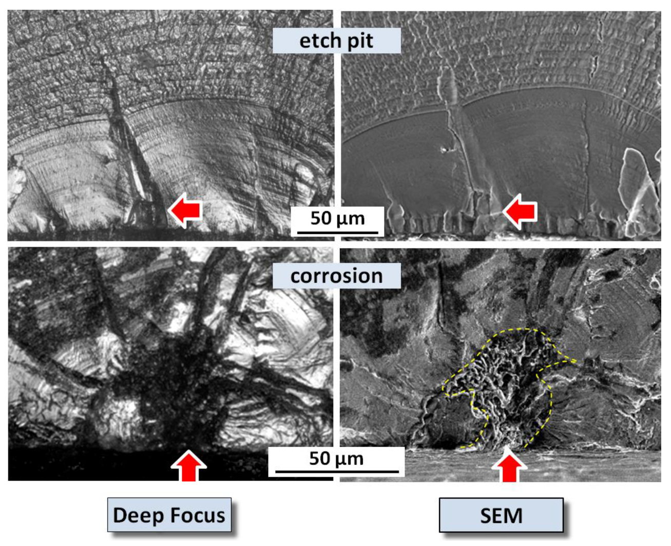
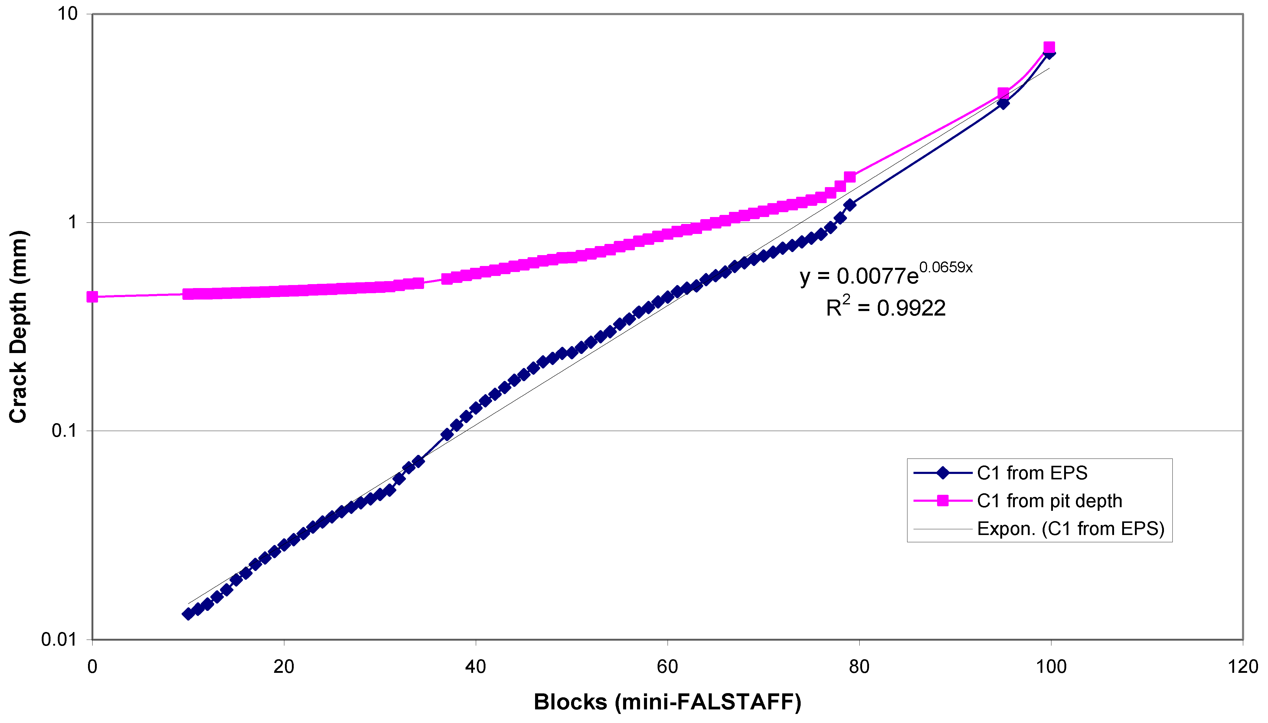
4. Differences between Crack Growth from Etch Pits and Corrosion Pits
- (i)
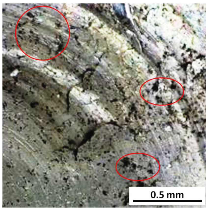
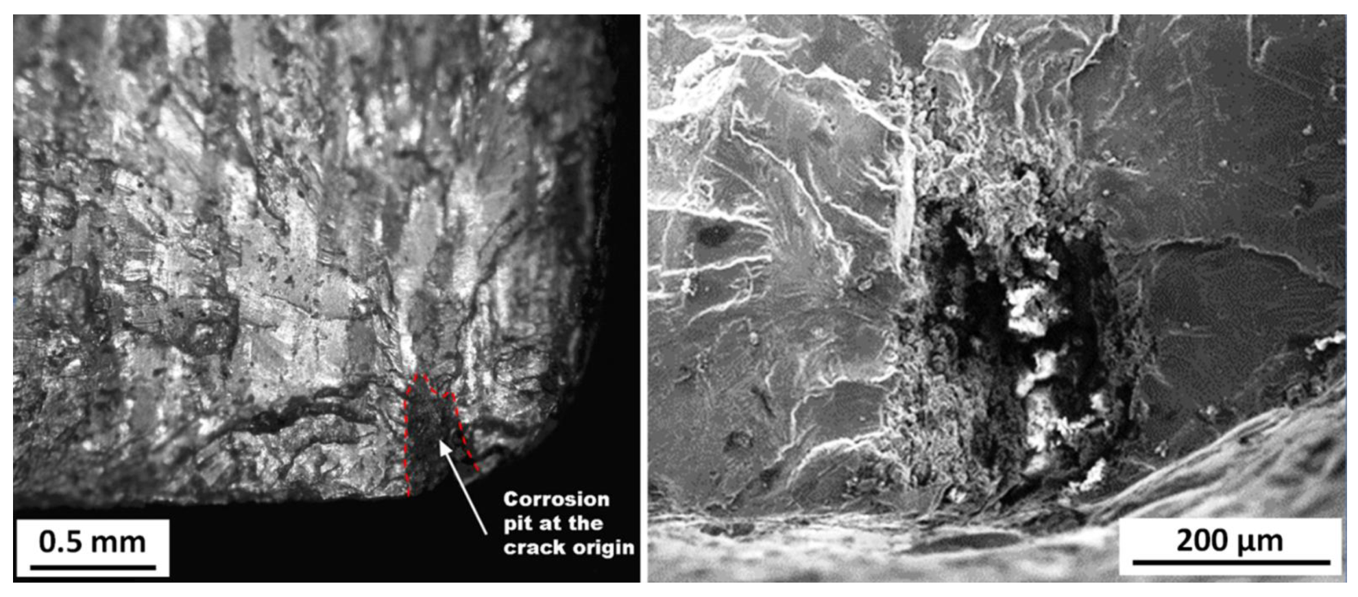
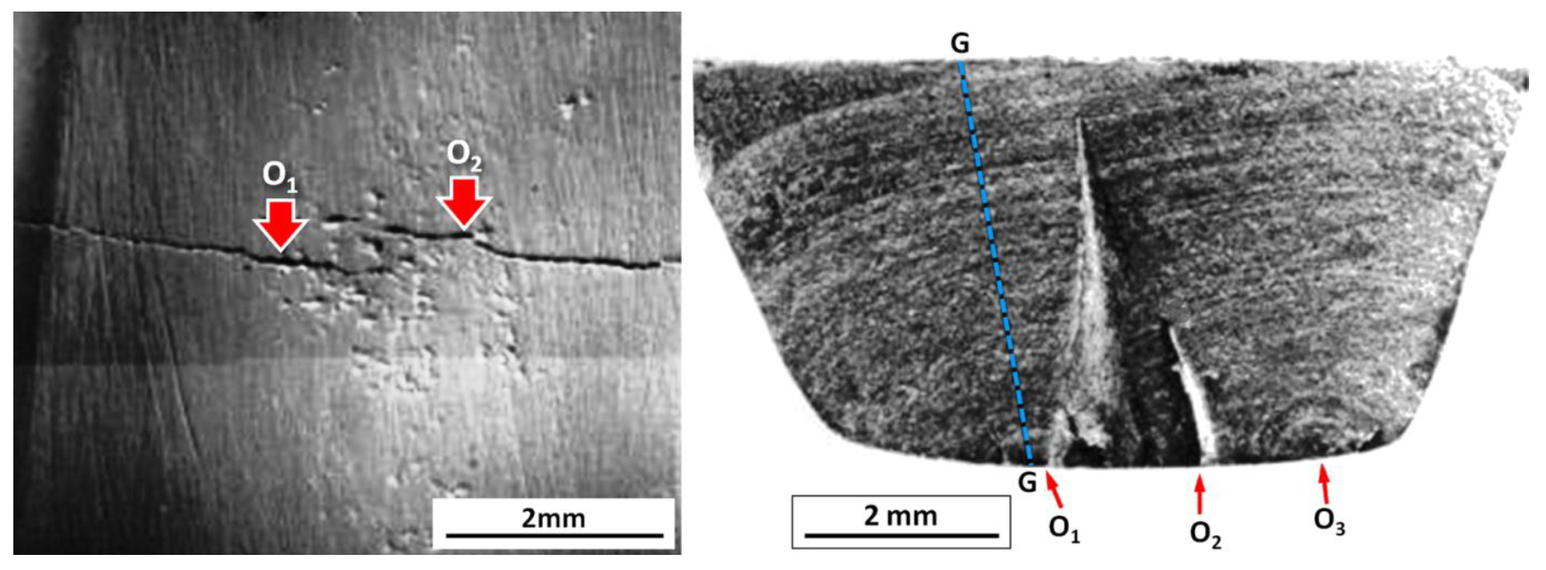
- Corrosion pits can have convoluted 3D shapes and geometries—they may be shallow depressions or cavities, deeper but spread out, as in Figure 9, or long and narrow, with sharp tips growing in various directions, particularly down grain boundaries. All these morphology variations can significantly affect the crack nucleation and propagation behaviour.
- (ii)
- In more detail, corrosion pit irregularities can cause fatigue crack nucleation at many positions above or below the eventual crack plane, and also at multiple positions along the pit boundary, as in Figure 9. The result is complex interference (crack ‘shadowing’) between small cracks, an ill-defined overall crack front and greater fracture surface roughness, and consequently less efficient early crack growth into the material. This situation may persist for several tenths of millimetres and result in significant deviations from lead crack behaviour. In turn, such deviations will considerably influence the fatigue crack growth life, since much of the life is spent in growing small cracks [40].
- (iii)
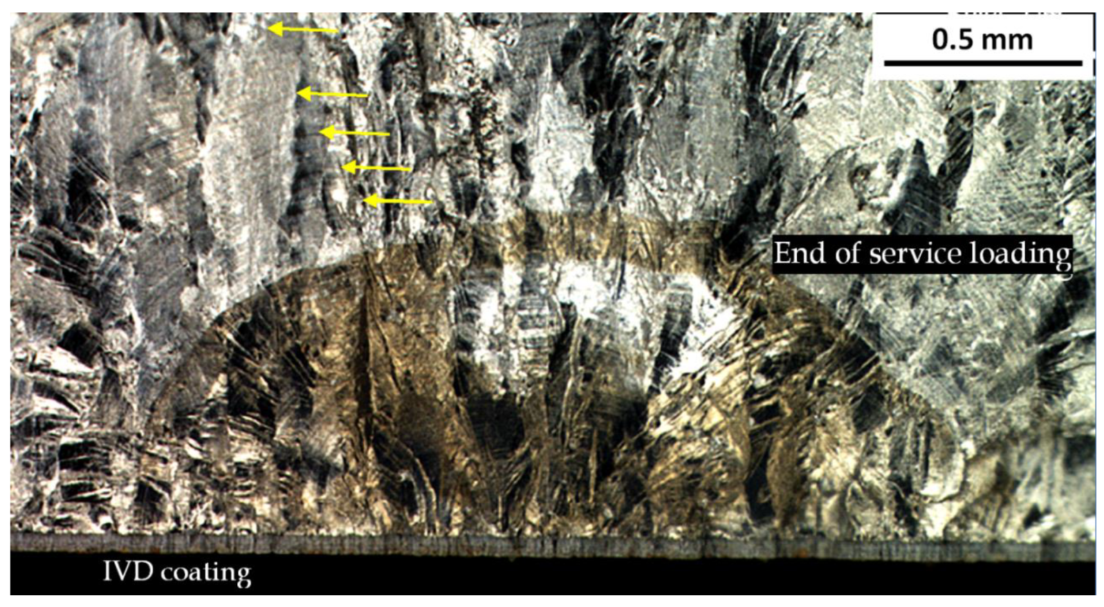
- Fatigue-nucleating pits need not be optimally located with respect to grain orientations (important for small cracks) and the local stresses in a component. This means that crack growth will be slower than for lead cracks.
4.1. AA7050-T7451 Y488 Wing Attachment Bulkhead
4.2. F/A-18 Trailing Edge Flap Hinge Lugs
4.3. F-111 Stiffener in the Upper Wing
4.4. Additional Remarks about EPS Estimates and Corrosion Pitting
5. Structural Assessment Methodology
- Corrosion is not considered from a durability perspective;
- The Standard requires that the cumulative probability of failure (CPOF) for the total airframe, owing to structural fatigue, be limited to 1/1000 in the life of type. This is mainly achieved by using the guidelines during design, followed by a representative full-scale fatigue test (FSFT). The demonstrated FSFT simulated flight hours until reaching a residual strength criterion are then divided by a scatter factor (SF) to achieve the required CPOF. The FSFT is assumed to represent the mean quality and build standard of the fleet; and the applied load history is assumed to represent the mean for aircraft usage;
- For primary structure, any crack in the FSFT must not reach the critical size (for 1.2 Design Limit Load (DLL)) and within a (lifetime X SF) of the spectrum loading; and
- Service fatigue loads are monitored and periodically reviewed.
5.1. An Assessment Methodology for Fatigue Cracking from Corrosion Pits, Exemplified by Figure 17
- (1)
- Undetected or unrepaired corrosion in a certified airframe will affect structural integrity only if a corrosion-nucleated fatigue crack reaches a critical crack size (acrit) before any other discontinuity-nucleated crack does so.
- (2)
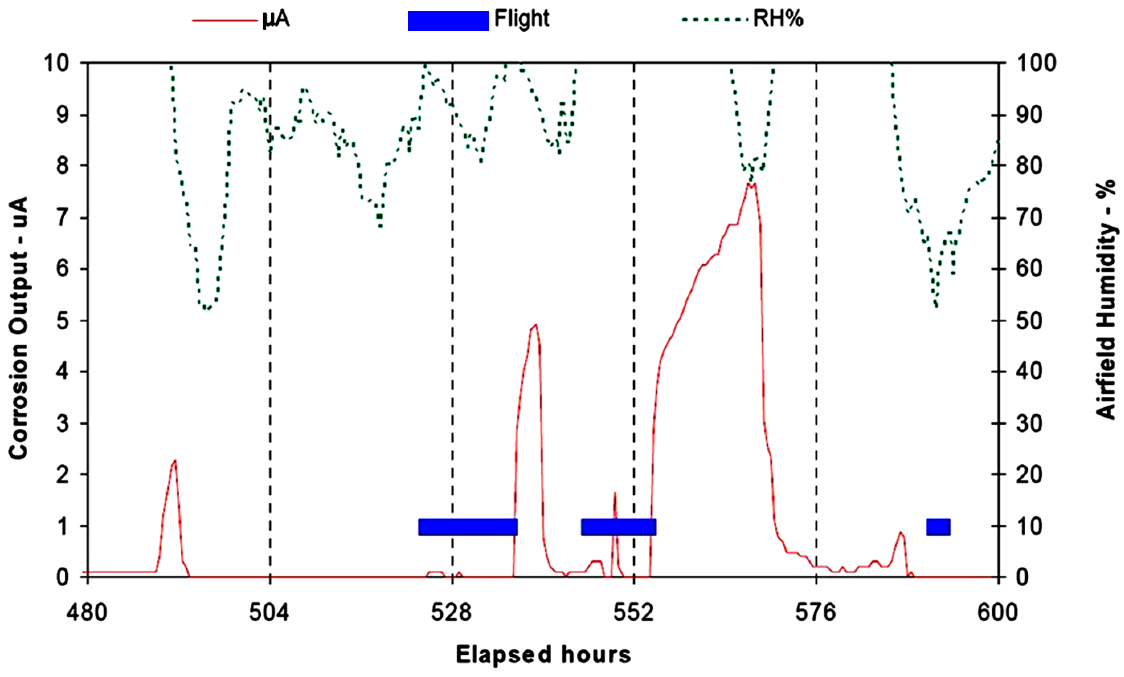
- Significant corrosion probably occurs only when the aircraft is parked at the air base. Hence, fatigue crack growth (largely or entirely under in-flight loading) is considered to be unaffected by possibly aggressive ground environments. In other words, fatigue crack growth data obtained from laboratory tests in ambient air are appropriate for the assessment (discounting potentially detrimental shelter environments; additionally, note that this approach is considered conservative by Burns et al. [18]).
5.2. The Proposed Framework, Based on the Lead Crack Approach
- Walk-around or other scheduled inspections are typically those when corrosion damage is found, and these would continue.
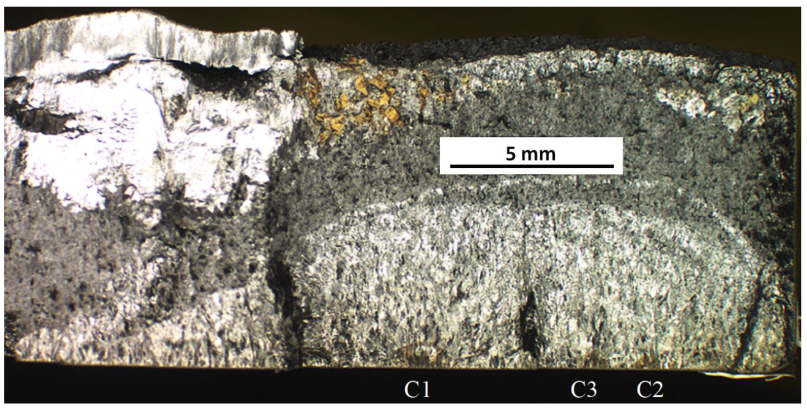
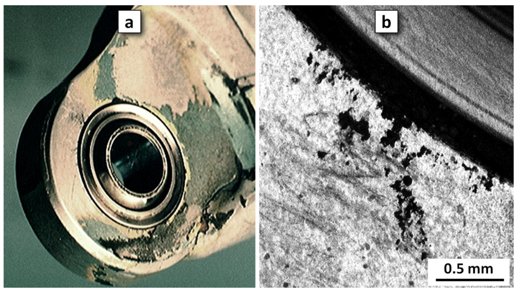
- If corrosion is found, its type and severity would be determined (see [56] for definitions of light, moderate and severe corrosion) (i.e., extent or coverage (minor severity here relates to static modes of potential failure related to the spread of the corrosion and depth of material to be removed in the subsequent repair)). There would also be inspection for any associated fatigue cracks (as was done for lugs such as those in Figure 12). Any detected fatigue cracks would be managed by established methods (note that the probability of multi-site cracking effects is considered very remote at the short intervals derived by the methodology). The particular inspection technique and thus the NDI detectability threshold should depend on the local configuration (e.g., eddy current for the fastener hole example in Figure 1). The presence of pitting should not affect the sensitivity of any suitable inspection type.
- If corrosion is due to pitting, and no cracking is detected, then the damage would be treated periodically (this will be determined according to the CIC type and the airbase environment) with corrosion inhibiting compounds (CICs) and left in place until the next maintenance period. The application of CICs is intended to prevent/reduce further corrosion, thereby limiting the difficulty of any repairs.
- During the remainder of the non-repair interval the corrosion should ideally be re-inspected to check for any increase and/or for detectable cracking.
- Any detected corrosion should ideally be mapped by location. This would help to identify fleet trends, and minimise the clean-up effort at the next scheduled maintenance.
- At the next scheduled maintenance, the corrosion would be cleaned up (normally by blending); and if material removal leaves the component(s) above allowable thickness limits, then the corrosion protection system would be restored and the aircraft returned to service.
6. Concluding Remarks
Author Contributions
Funding
Institutional Review Board Statement
Informed Consent Statement
Data Availability Statement
Acknowledgments
Conflicts of Interest
References
- Aircraft Structural Integrity Program (ASIP). Department of Defense Standard Practice MIL-STD-1530D, United States Air Force, 1690; Air Force Pentagon: Washington, DC, USA, 2016. [Google Scholar]
- Jones, R. The effect of environmental degradation on aircraft structural integrity. In In Proceedings of the 1st Corrosion and Materials Degradation Web Conference, 17–19 May 2021. [Google Scholar]
- Jones, K.; Hoeppner, D.W. The interaction between pitting corrosion, grain boundaries, constituent particles during corrosion fatigue of 7075-T6 aluminum alloy. Int. J. Fatigue 2009, 31, 686–692. [Google Scholar] [CrossRef]
- Advisory Group for Aerospace Research and Development. Corrosion Fatigue of Aircraft Materials; AGARD Report No.659; NATO: Neuilly-sur-Seine, France, 1977. [Google Scholar]
- Advisory Group for Aerospace Research and Development. The Fatigue in Aircraft Corrosion Testing (FACT) Programme; AGARD Report No. 713; NATO: Neuilly-sur-Seine, France, 1989. [Google Scholar]
- Larrosa, N.O.; Akid, R.; Ainsworth, R.A. Corrosion-fatigue: A review of damage tolerance models. Int. Mater. Rev. 2017, 63, 283–308. [Google Scholar] [CrossRef] [Green Version]
- Molent, L. Managing airframe fatigue from corrosion pits—A proposal. Eng. Fract. Mech. 2015, 137, 12–25. [Google Scholar] [CrossRef]
- Molent, L.; Barter, S.; Wanhill, R.J.H. The decoupling of corrosion and fatigue for aircraft service life management. In Proceedings of the ICAF 2015, Structural Integrity: Embracing the Future, Helsinki, Finland, 1–5 June 2015; Siljander, A., Ed.; Espoo VTT: Espoo, Finland, 2015. [Google Scholar]
- Loader, C.; Crawford, B.R.; Sharp, K.; Molent, L. A Proposal for the Management of Detected Pitting Corrosion for the F/A-18 Hornet; Report DSTO-TR-2976; Defence Science and Technology Organisation: Melbourne, Australia, 2014. [Google Scholar]
- Donnelly, D.; Van Gulick, Z.; Barter, S. F/A-18 Hornet Main Landing Gear Wheel Cracking; Report DST-Group-TR-3533; Defence Science and Technology Group: Melbourne, Australia, 2018. [Google Scholar]
- Sankaran, K.K.; Perez, R.; Jata, K.V. Effects of pitting corrosion on the fatigue behavior of aluminum alloy 7075-T6: Modeling and experimental studies. Mater. Sci. Eng. A 2001, 297, 223–229. [Google Scholar] [CrossRef]
- Trathen, P. Corrosion monitoring systems on military aircraft. In Proceedings of the 18th International Corrosion Conference, Perth, Australia, 20–24 November 2011; pp. 1231–1240. [Google Scholar]
- Barter, S.A.; Molent, L. Investigation of an in-service crack subjected to aerodynamic buffet and manoeuvre loads and exposed to a corrosive environment. In Proceedings of the ICAS 2012, 28th Congress of the International Council of the Aeronautical Sciences, Brisbane, Australia, 23–28 September 2012. Paper ICAS 2012–7.9. [Google Scholar]
- Barter, S.; Molent, L. Service fatigue cracking in an aircraft bulkhead exposed to a corrosive environment. Eng. Fail. Anal. 2013, 34, 181–188. [Google Scholar] [CrossRef]
- Barter, S.; Molent, L. Fatigue cracking from a corrosion pit in an aircraft bulkhead. Eng. Fail. Anal. 2014, 39, 155–163. [Google Scholar] [CrossRef]
- Tamboli, D.Z.; Jones, R.; Barter, S. Decoupling of fatigue and corrosion in AA7050-T7451. In Proceedings of the ICAF 2017, Nagoya, Japan, 5–9 June 2017; VTT Information Service, Espoo VTT: Espoo, Finland, 2017; Volume 3, pp. 1546–1557. [Google Scholar]
- Burns, J.T.; Gangloff, R.P.; Bush, R.W. Effect of environment on corrosion induced fatigue crack formation and early propagation in aluminum alloy 7075-T651. In Proceedings of the Department of Defense Corrosion Conference, La Quinta, CA, USA, 31 July–5 August 2011. [Google Scholar]
- Burns, J.T.; Gangloff, R.P. Scientific advances enabling next generation management of corrosion induced fatigue. Procedia Eng. 2011, 10, 362–369. [Google Scholar] [CrossRef]
- Lang, M.; Stol, C.; Hack, T.; Holzinger, V. Technology for corrosion management of aging aircraft. In Proceedings of the 2001 USAF Aircraft Structural Integrity Program Conference, Williamsburg, VA, USA, 11–13 December 2001. [Google Scholar]
- Wanhill, R.J.H. Flight Simulation Fatigue Crack Growth Guidelines; Report NLR-TP-2001-545; National Aerospace Laboratory NLR: Amsterdam, The Netherlands, 2001. [Google Scholar]
- Wanhill, R.J.H.; Koolloos, M.F.J. Fatigue and corrosion in aircraft pressure cabin lap splices. Int. J. Fatigue 2001, 23, S337–S347. [Google Scholar] [CrossRef]
- Wanhill, R.J.H. Aircraft corrosion and fatigue damage assessment. In Proceedings of the 1995 USAF Structural Integrity Program Conference, San Antonio, TX, USA, 28–30 November 1995; Report WL-TR-96-4094. Waggoner, J.K., Lincoln, J.W., Rudd, J.L., Eds.; Wright-Patterson Air Force Base: Dayton, OH, USA, 1996; Volume II, pp. 983–1027. [Google Scholar]
- Jones, R. Fatigue crack growth and damage tolerance. Fatigue Fract. Eng. Mater. Struct. 2014, 37, 463–483. [Google Scholar] [CrossRef]
- Jones, R.; Peng, D.; Singh, R.K.; Huang, P.; Tamboli, D.; Matthews, N. On the growth of fatigue cracks from material and manufacturing discontinuities under variable amplitude loading. J. Met. 2015, 67, 1385–1391. [Google Scholar] [CrossRef]
- Wanhill, R.J.H. Some Practical Considerations for Fatigue and Corrosion Damage Assessment of Ageing Aircraft; Report NLR TP 96253; National Aerospace Laboratory NLR: Amsterdam, The Netherlands, 1996. [Google Scholar]
- Hoeppner, D.W.; Arriscorreta, C.A. Exfoliation corrosion and pitting corrosion and their role in fatigue predictive modelling: State-of-the-art review. Int. J. Aerosp. Eng. 2012, 191879. [Google Scholar] [CrossRef] [Green Version]
- NATO. Corrosion Fatigue and Environmentally Assisted Cracking in Aging Military Vehicles; RTO AGARDograph AG-AVT-140; NATO Research and Technology Organisation: Neuilly-sur-Seine, France, 2011. [Google Scholar]
- Du, M.L.; Chiang, F.P.; Kagwade, S.V.; Clayton, C.R. Damage of Al 2024 alloy due to sequential exposure to fatigue, corrosion and fatigue. Int. J. Fatigue 1998, 20, 743–748. [Google Scholar] [CrossRef]
- Barter, S.A.; Molent, L.; Wanhill, R.J.H. Typical fatigue-initiating discontinuities in metallic aircraft structure. Int. J. Fatigue 2012, 41, 11–22. [Google Scholar] [CrossRef]
- White, P.; Molent, L.; Barter, S. Interpreting fatigue test results using a probabilistic fracture approach. Int. J. Fatigue 2005, 27, 752–767. [Google Scholar] [CrossRef]
- Molent, L.; Dixon, B. The airframe metal fatigue problem space. Int. J. Terraspace Sci. Eng. 2020, 12, 1–7. [Google Scholar]
- Barter, S.; Russell, D. Corrosion Pitting as a Fatigue Crack Initiator in AA7050-T74511 under a Fighter Spectrum; Report DSTO-TR-2913; Defence Science and Technology Organisation: Melbourne, Australia, 2013. [Google Scholar]
- Crawford, B.R.; Loader, C.; Sharp, P.K. A Proposed Roadmap for Transitioning DSTO’s Corrosion Structural Integrity Research into Australian Defence Force Service; Report DSTO-TR-2475; Defence Science and Technology Organisation: Melbourne, Australia, 2010. [Google Scholar]
- Wanhill, R.J.H.; Barter, S.A.; Molent, L. Fatigue Crack Growth Failure and Lifing Analyses for Metallic Aircraft Structures and Components; Springer Briefs in Applied Sciences and Technology; Springer: Dordrecht, The Netherlands, 2019. [Google Scholar]
- Molent, L.; Sun, Q.; Green, A.J. Characterisation of equivalent initial flaw sizes in 7050 aluminium alloy. Fatigue Fract. Eng. Mater. Struct. 2006, 29, 916–937. [Google Scholar] [CrossRef]
- Molent, L. A review of equivalent pre-crack sizes in aluminium alloy 7050-T7451 (invited review paper). Fatigue Fract. Eng. Mater. Struct. 2014, 37, 1055–1074. [Google Scholar] [CrossRef]
- Smith, C. Fatigue Crack Initiation from Pitting Introduced during the Anodising Process; Report DSTO-TR-2729; Defence Science and Technology Organisation: Melbourne, Australia, 2012. [Google Scholar]
- Smith, S.W.; Newman, J.A.; Piascik, R.S. Simulation of Fatigue Crack Initiation at Corrosion Pits with EDM Notches; NASA/TM-2003-212166; NASA Langley Research Center: Hampton, VA, USA, 2003. [Google Scholar]
- Burns, J.T.; Larsen, J.M.; Gangloff, R.P. Driving forces for localized corrosion-to-fatigue crack transition in Al–Zn–Mg–Cu. Fatigue Fract. Eng. Mater. Struct. 2011, 34, 745–773. [Google Scholar] [CrossRef]
- Molent, L.; Barter, S.A.; Wanhill, R.J.H. The lead crack fatigue lifing framework. Int. J. Fatigue 2011, 33, 323–331. [Google Scholar] [CrossRef]
- Molent, L.; Dixon, B.; Barter, S.A.; Swanton, G. Outcomes from the fatigue testing of seventeen centre fuselage structures. Int. J. Fatigue 2018, 111, 220–232. [Google Scholar] [CrossRef]
- FALSTAFF. Description of a Fighter Aircraft Loading Standard for Fatigue Evaluation, Combined Report of the F+W (Switzerland), LBF (Germany), NLR (Netherlands), IABG (Germany), NTIS Issue Number 197708; National Technical Reports Library: Springfield, VA, USA, 1976. [Google Scholar]
- Dixon, B.; Molent, L.; Barter, S.A.; Mau, V. Flaw Identification through the Application of Loads: Teardown of the Centre Barrel from USN F/A-18D Buno 163507; Report DSTO-TR-1740; Defence Science and Technology Organisation: Melbourne, Australia, 2005. [Google Scholar]
- Smith, C.; Donnelly, D. Case studies of fatigue failures in defence aircraft components. Adv. Mat. Res. 2014, 891–892, 81–86. [Google Scholar] [CrossRef]
- Sharp, P.K.; Clayton, J.Q.; Clarke, G. The fatigue resistance of peened 7050-T7451 aluminium alloy—Repair and re-treatment of a component surface. Fatigue Fract. Eng. Mater. Struct. 1994, 17, 243–252. [Google Scholar] [CrossRef]
- Barter, S.; Sharp, P.K.; Clark, G. The failure of an F/A-18 trailing edge flap hinge. Eng. Fail. Anal. 1994, 1, 255–266. [Google Scholar] [CrossRef]
- Cox, A.F.; Goldsmith, N.T.; Bland, L.M.; Glanvill, D.W.; Patching, C.A. Preliminary Report on Investigation into Failure of F111C A8–129 Wing Pivot Fitting in Cold Proof Load Test; Memorandum ARL-Mat-Tech Memo-383; Defence Science and Technology Organisation: Melbourne, Australia, 1983. [Google Scholar]
- Cox, A.F. Fatigue Cracking in the Upper Plate of Wing Pivot Fittings in F111 Aircraft; Aircraft Materials Report 121; Defence Science and Technology Organisation: Melbourne, Australia, 1988. [Google Scholar]
- Murakami, Y.; Endo, M. Quantitative evaluation of fatigue strength of metals containing various small defects or cracks. Eng. Fract. Mech. 1983, 17, 1–15. [Google Scholar]
- Design and Airworthiness Requirements for Service Aircraft Volume 1—Aeroplanes; Defence Standard 00–970, Issue 1; Ministry of Defence: Foulness Island, UK, 1983.
- Molent, L.; Barter, S.A. A comparison of crack growth behaviour in several full-scale airframe fatigue tests. Int. J. Fatigue 2007, 29, 1090–1099. [Google Scholar] [CrossRef]
- Lincoln, J.W.; Melliere, R.A. Economic life determination for a military aircraft. J. Aircr. 1999, 36, 737–742. [Google Scholar] [CrossRef]
- Molent, L. Fatigue crack growth from flaws in combat aircraft. Int. J. Fatigue 2010, 32, 639–649. [Google Scholar] [CrossRef]
- Schijve, J. Fatigue prediction and scatter. Fatigue Fract. Eng. Mater. Struct. 1994, 17, 381–396. [Google Scholar] [CrossRef]
- Murakami, Y.; Miller, K.J. What is fatigue damage? A view point from the observation of low cycle fatigue process. Int. J. Fatigue 2005, 27, 991–1005. [Google Scholar] [CrossRef]
- Wallace, W.; Hoeppner, D.W.; Kandachar, P.V. AGARD Corrosion Handbook Volume 1: Aircraft Corrosion: Causes and Case Histories; AGARDograph AGARD-AG-278; Advisory Group for Aerospace Research and Development, NATO: Neuilly-sur-Seine, France, 1978. [Google Scholar]






Publisher’s Note: MDPI stays neutral with regard to jurisdictional claims in published maps and institutional affiliations.. |
© 2021 by the authors. Licensee MDPI, Basel, Switzerland. This article is an open access article distributed under the terms and conditions of the Creative Commons Attribution (CC BY) license (https://creativecommons.org/licenses/by/4.0/).
Share and Cite
Molent, L.; Wanhill, R. Management of Airframe In-Service Pitting Corrosion by Decoupling Fatigue and Environment. Corros. Mater. Degrad. 2021, 2, 493-511. https://doi.org/10.3390/cmd2030026
Molent L, Wanhill R. Management of Airframe In-Service Pitting Corrosion by Decoupling Fatigue and Environment. Corrosion and Materials Degradation. 2021; 2(3):493-511. https://doi.org/10.3390/cmd2030026
Chicago/Turabian StyleMolent, Loris, and Russell Wanhill. 2021. "Management of Airframe In-Service Pitting Corrosion by Decoupling Fatigue and Environment" Corrosion and Materials Degradation 2, no. 3: 493-511. https://doi.org/10.3390/cmd2030026
APA StyleMolent, L., & Wanhill, R. (2021). Management of Airframe In-Service Pitting Corrosion by Decoupling Fatigue and Environment. Corrosion and Materials Degradation, 2(3), 493-511. https://doi.org/10.3390/cmd2030026


