Abstract
A theoretical study of the adsorption of lithium–sulfur molecules (Li2S and Li2S2) on graphene with three and four vacancies was conducted. The study analyzed the stability, adsorption geometry, electronic structure, charge distribution, and forming bonds between the molecule and the substrates. It has been demonstrated that both types of defects result in stable adsorptions; however, the underlying mechanisms differ. The three-vacancy graphene exhibits a site that favors the adsorption through bonds between S atoms and the substrate, while the graphene with four vacancies promotes the anchoring of molecules through Li atoms. The mechanism associated with the three-vacancy graphene results in increased exothermic adsorption energies.
1. Introduction
Lithium–sulfur (Li–S) batteries have been identified as a potential breakthrough in the field of energy storage. These batteries exhibit a high energy density, with a rating of approximately 2600 Wh·kg−1. They are cost-effective, and sulfur, the primary component in their composition, is readily available and has minimal environmental impact. This makes them well-suited to applications that require light, powerful batteries [1,2]. Despite the significant investment and research in this field, Li–S batteries remain uncommon. There are still fundamental challenges in their electrochemistry that hinder long-term stability and efficiency [3]. A significant number of review articles have recently been published explaining the challenges, achievements, and opportunities of Li–S batteries. Ding et al. presented the recent advances in solid-state lithium–sulfur (Li–S) batteries, focusing on optimized solid electrolytes, Li–ion transport, and electrode/electrolyte interfaces to enhance safety and longevity [4]. Zhao et al. reviewed strategies to control the sulfur electrochemistry for stable high-loading cathodes [5]. Hou et al. analyzed lithium metal anode challenges from soluble lithium polysulfides (LiPSs) and summarized the anode protection strategies [6]. Deshmukh et al. highlighted solid-state Li–S batteries as solutions to safety and cycling limitations, reviewing ion transport and interface engineering [7]. Raza et al. identified limitations such as the low sulfur utilization, polysulfide shuttling, and lithium anode degradation, and analyzed the advances in materials synthesis, structural design, and 3D-printing for commercialization [8]. Lv et al. discussed high-voltage LCO cathodes, focusing on surface engineering, electrolyte design, and CEI optimization for stability and self-healing [9]. Liu et al. reviewed low-temperature Li–S battery performance, detailing the mechanisms, challenges, and recent advances [10]. Shao et al. summarized the LiPS confinement, redox regulation, electrocatalysis, and electrolyte design, highlighting the gap between coin cells and pouch cells [11]. Jiao et al. analyzed the low-temperature failure mechanisms and advances in electrolyte, cathode, and separator design [12]. Shi et al. addressed lean-electrolyte Li–S batteries, reviewing the electrode porosity, electrocatalysis, active materials, electrolyte regulation, and Li protection [13]. Pathak et al. discussed the lab-to-industry scale gaps, highlighting sulfur cathode insulation, polysulfide shuttling, lithium dendrites, and strategies for scalable pouch cells [14]. Qian et al. emphasized the practical applications, including high-loading cathodes, lean electrolytes, and solid-state designs [15]. Sawan et al. reviewed the advanced materials, including 3D sulfur–carbon composites, MOFs, COFs, MXenes, solid/gel electrolytes, and lithium anode protection, addressing large-scale manufacturing and commercialization [16]. Sharma et al. reported on next-generation energy storage, covering Li–S, Li–air, Zn–ion, and Na–ion batteries, supercapacitors, and hybrid capacitors, highlighting the advances in fabrication, electrode materials, electrolytes, and economic considerations [17].
A significant challenge concerns the formation and breakdown of lithium polysulfides (Li2Sx, 4 ≤ x ≤ 8). These compounds are formed during the redox conversion of sulfur [18]. These compounds exhibit a high degree of solubility in conventional electrolytes, facilitating their movement between the cathode and the lithium anode. This phenomenon, known as the “shuttle effect”, causes the continuous loss of active material, parasitic reactions at the anode, and a low Coulombic efficiency [19]. Additionally, sulfur and the final product (Li2S) exhibit poor electrical conductivity, requiring the incorporation of specialized materials, which complicates the battery design process [20]. This inherent challenge in the utilization of Li–S batteries is a significant impediment to their widespread adoption. In an effort to address the issue of polysulfide, various approaches have been explored. At the cathode level, efforts have been concentrated on designing conductive hosts, including porous carbons [21], metal oxides [22], metal sulfides [23], and MXenes [24], which can physically confine polysulfides and chemically anchor them through strong interactions.
Recent developments have described several strategies to understand and inhibit the shuttle effect [25,26,27,28,29]. Materials composed of carbon, including conducting polymers, carbon nanotubes, graphene, and activated carbon, have garnered significant attention due to their cost-effectiveness, accessibility, stability, and exceptional heat and electrical conductivity [30,31]. The integration of graphene within sulfur cathodes has been demonstrated to be a beneficial measure. Firstly, graphene solves the electrical problem with sulfur and Li2S, enabling rapid charge movement and enhanced performance [32]. Secondly, the large surface area of graphene allows for the even dispersion of sulfur and accommodates volume changes during battery cycling [33]. Of particular significance is the observation that the addition of other elements or the mixing of graphene with polar materials results in its capacity to adhere to polysulfides, thereby ensuring their retention within the cathode and preventing them from compromising the integrity of the electrolyte [34]. This not only reduces the shuttle effect but also enhances the battery’s efficiency and prolongs its lifespan. A substantial number of articles have been published which summarizes the latest developments in graphene-based Li–S batteries. These articles focus on the utilization of graphene in sulfur positive electrodes and lithium negative electrodes, and as layers in between [35,36].
Through experimental and computer-simulation-based research, it has been determined that graphene could play a significant role in mitigating the shuttle effect, paving the way for the development of enhanced Li–S batteries that have the potential for commercialization in the future. The utilization of computer calculations employing Density Functional Theory (DFT) has facilitated a comprehensive understanding of the behavior of polysulfides and the development of graphene-based solutions. DFT enables the examination of the atomic level, thus facilitating the observation of the strength of polysulfides’ attachment to graphene, in addition to their capacity for charge exchange. For instance, calculations have demonstrated that unmodified graphene exhibits minimal adhesion to polysulfides [37]. The addition of other elements or polar groups has been shown to increase the binding energy and form strong chemical bonds [38,39]. These concepts have resulted in the synthesis of doped graphene, graphene–oxide blends, and graphene–metal composites, which exhibit enhanced performance in experimental settings. DFT simulations have also facilitated the testing of new graphene designs and the prediction of where polysulfides will attach, thereby enabling the development of enhanced cathode materials [40,41]. The recent progress in how to solve interfacial problems and design better S mediators for high-performance Li–S batteries is discussed in [42].
A variety of design choices, including the quantity of sulfur utilized, the thickness of the electrolyte, the discharge capacity, the voltage, and the sulfur content of the cathode, are examined to elucidate their impact on the energy density [40,42]. Chen et al. provide an overview of the latest computational methods (DFT, molecular dynamics, and finite element analysis) for Li–S batteries, compare their advantages, and summarize how they can be used to address issues with Li–S batteries [40]. The chemical inertness of plain graphene, attributable to its structural configuration, is a limiting factor in its capacity for bonding with other materials, such as polysulfides. A pivotal method of enhancing the functionality of graphene is to deliberately introduce defects, particularly vacancies, which disrupt the crystalline structure and result in the formation of bonds of a different nature [42].
Our research group has utilized DFT calculations to investigate the stability of transition metal atoms on graphene, considering various types of vacancies and the incorporation of boron [43,44]. A comparison of this to nickel clusters deposited on unmodified graphene demonstrated that the combination of vacancy defects with nickel results in an increase in band gaps. Nickel clusters of different sizes also can make graphene with three, four, or six vacancies magnetic [45,46]. Ambrusi et al. conducted a study on the storage of hydrogen by spillover on a Ni4 cluster in a three-vacancy graphene sheet, observing a significant reduction in activation energy in comparison to pristine systems [47]. Faccio et al. present findings on the distortion of graphene’s structure and electronics due to vacancies and boron atoms. This research utilized total energy and band structure calculations to explore the underlying mechanisms [48]. Structural modifications have been observed in graphene when multi-atom vacancies are introduced, resulting in the emergence of a net magnetic moment that varies with both the size and shape of the vacancies. The authors argue that the structural characteristics of multiple vacancies in graphene can serve as a diagnostic indicator of the system’s magnetic behavior [49,50]. Mombrú et al. established the correlation between the rippling of the graphene sheet and the distortion of the vacancy for a transition metal atom in an eight-order multivacancy [51]. The magnetic and electronic properties of multivacancy graphene systems with one or two sulfur atoms added were also studied using DFT. The locations of the sulfur atoms are determined by pentagonal shapes in the optimized system, or by concave four-membered structures in the case of a vacancy, if these shapes are not present. The electronic structure and magnetism of these systems undergo significant alterations due to the presence of dangling bonds from the sulfur atoms [52].
Rao et al. modelled the immobilization of sulfides on cathodes via B-doped atomic-layer carbon materials on graphene, γ-graphyne (GY) and γ-graphdiyne (GDY). They found that B-doped graphdiyne is a promising host material, as it exhibits a stronger attraction to Li2Sn than other selected materials, as well as an exceptional sulfur loading of approximately 70 wt% [53]. Jyothirmai and Ravva investigated the interplay between the effects of confinement and the interaction energy of the Li2S2N species with CNTs, demonstrating that the interaction is electrostatic [54]. Yi et al. obtained some very interesting results regarding the adsorption of Li2S2/Li2S on graphene with a single vacancy. The presence of this defect alters the local electronic structure of graphene, enhancing the adsorption energy of polysulfides, especially the insoluble final discharge product. When a Li2S molecule approaches the vacancy, the S atom in the molecule directly connects to a C atom with an unpaired electron in the graphene. This unique S–C binding behavior has rarely been reported previously. Compared with other Li–polysulfides, the adsorption height of Li2S on the defected graphene is the lowest due to this strong S–C binding. For the Li2S2 molecule, the adsorption energy and adsorption height are smaller than for Li2S [55].
Despite the significant advancements in research and development related to Li–S batteries and graphene-based materials, there remains a limited understanding of the impact of multi-vacancy defects on the adhesion of Li2S and Li2S2 to graphene. While several theoretical studies have explored the interaction of lithium polysulfides with graphene-based substrates, the majority have focused on pristine graphene or simple mono-vacancy defects. A major drawback of these studies is the limited binding strength, often failing to effectively anchor the Li–S species. To address this, our work introduces a unique theoretical investigation focusing on the multi-vacancy defective graphene (specifically 3V and 4V structures). This approach is highly innovative because it creates fundamentally different and more reactive adsorption sites than single-atom defects, leading to distinct and much stronger adsorption mechanisms for Li2S and Li2S2 molecules. Furthermore, we uniquely compare the underlying electronic and structural differences between the 3V and 4V substrates, demonstrating a novel pathway for substrate design and control. The results presented herein provide critical atomic-level insights that distinguish our work and offer a significant contribution to the development of high-performance Li–S battery cathodes.
2. Materials and Methods
2.1. Methodology
The VASP simulation package code, version 5.3.1, is utilized to perform spin-polarized density functional theory (DFT) calculations [56,57,58]. The cut-off energy for the plane-wave basis set was determined to be 500 eV. For the exchange-correlation term, the general gradient approximation (GGA) parametrized by the Perdew–Burke–Ernzerhof functional (PBE) was used [59]. The projector augmented wave (PAW) pseudopotential method was employed to describe electron-ion core interaction [60]. Van der Waals interactions were analyzed using the DFT-D3 correction method, as implemented by Grimme et al. [61]. All structures were optimized until the forces acting on each atom were smaller than 2 × 10⁻² eV Å−1 and the energy convergence was smaller than 10−4 eV. An automatically generated gamma-centered k-points mesh in the irreducible part of the Brillouin zone of 4 × 4 × 1 k-point sampling grid was used for reciprocal space integration, following the Monkhorst–Pack scheme [62]. A denser k-point mesh of 10 × 10 × 1 was employed to compute the binding energies, density of states (DOS) curves, and projected density of states (PDOS) curves.
Moreover, we compute the localized electronic function (ELF) and the Crystal Orbital Hamilton Population (COHP) [63,64], obtaining the partial COHP (pCOHP) and integral COHP (ICOPH) per specific bonds. For the latter, we have performed calculations on LOBSTER (Local-Orbital Basis Suite Towards Electronic-Structure Reconstruction) software, version 5.1.1 [65,66].
2.2. Model
To ensure the absence of interaction among periodic images, the 3V-graphene and 4V-graphene models were constructed with 69 and 68 carbon atoms, respectively, and positioned within a supercell of 14.76 Å × 14.76 Å × 20 Å. This configuration corresponds to a supercell composed of 6 × 6 primitive cells, with a vacuum space of 20 Å perpendicular to the carbon layer. Our study assumes the presence of specific, clean 3V and 4V defects. The practical synthesis of graphene with a high density of such specific defects is challenging. The feasibility of creating these structures is often driven by high-energy electron or ion irradiation (e.g., in a transmission electron microscope, TEM), where kinetic processes overcome the large energy barriers. Lehtinen et al. have observed stable multiple-vacancy configurations, such as the well-known double vacancy (2V) which rearranges to form 5- and 9-membered rings. Larger defects like triple (3V) and quadruple (4V) vacancies are known to form through complex bond reconstruction [67]. Figure 1 shows the optimized structures for the optimized clean defected graphene layers and isolated molecules.
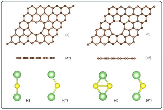
Figure 1.
Schematic frontal and top view for (a,a*) 3V-graphene, (b,b*) 4V-graphene, (c,c*) Li2S, and (d,d*) Li2S2. All structures are represented in their isolated form, before adsorption. Carbon, lithium, and sulfur atoms are shown in brown, green, and yellow, respectively.
As illustrated in Figure 1a, the three-vacancy defected graphene structure undergoes a reconstruction process, resulting in a heart-shaped configuration. This structural transformation involves the intercalation of two pentagonal rings between hexagonal rings, thereby encircling the defect hole. Additionally, the defect zone exhibits a carbon atom with a coordination two, an occurrence that deviates from the expected coordination three. The mean bond distances for the carbons that constitute the perimeter of the graphene defect hole are 1.79 Å, 1.48 Å, and 1.36 Å for the pentagonal rings and hexagonal rings, and the carbons bonded to the C with a coordination two, respectively. As indicated in Figure 1b, the graphene with four vacancies is reconstructed, containing three pentagonal rings intercalated by hexagonal rings, not only on the sides but also in the upper part. The C–C bond distances of the hole perimeter are 1.71 Å and 1.5 Å for the pentagonal and hexagonal rings, respectively. The C–C bond distances in 3V-graphene and 4V-graphene increase, relative to the pristine graphene value (1.42 Å), by 20–26% in hexagonal rings and by 4–6% in pentagonal rings. In contrast, the C–C bond associated with the carbon atom with dangling bonds is shortened by 4%. These structural variations, when combined with the angle’s aperture for C–C bonds along the perimeter of the defect hole, result in enhanced reactivity and a suitable location for the attachment of atoms, molecules, or impurities.
The adsorption energies, represented as Eads in eV, were calculated as the difference between the total energy of the system after adsorption (Eadsorbate⁄substrate) and the energy of the isolated sulfide (Li2S or Li2S2) in a box (Eadsorbate) plus the energy of the clean 3V- or 4V-graphene (Esubstrate) as follows:
For the Eads, a more negative value indicates a more favorable adsorption site; a positive value means that the adsorption is an endothermic reaction, while a negative value indicates that the adsorption is an exothermic reaction.
The electronic structure and bonding were analyzed through the calculation of Bader charges [63], overlap population (OP), and bond order values (BO), using the Chargemol code [64,65,66].
The charge density difference was computed by the following:
where the first two terms, and , are the densities of the systems nV-graphene for n = 3- and 4-vacancy defects with and without the adsorbed molecule, respectively, using the atom positions for the relaxed molec@nV-graphene structures. The is the molecule density on the adsorption position without the nV-graphene.
3. Results and Discussion
3.1. Adsorption Energies, Stability, and Geometry
In order to identify the most energetically favorable adsorption configurations of Li2S and Li2S2 on defected graphene, we explored a variety of initial adsorption geometries. The systems were thoroughly analyzed, and the adsorption energies (Eads) were calculated to evaluate the stability of each configuration. Please refer to Table 1 for a summary of the Eads values for the most stable configurations.

Table 1.
Adsorption energy (Eads) and magnetic moment () for the 3V-graphene and 4V-graphene after Li2S and Li2S2 adsorption.
Our calculations were performed in a vacuum. A real Li–S battery operates in a complex liquid electrolyte, typically a mixture of solvents (like DOL/DME) and a lithium salt (like LiTFSI). The liquid electrolyte introduces two competing effects: solvent molecule competition and dielectric screening. However, the purpose of our DFT calculations is primarily to determine the relative strength and preferred geometry of interaction across different adsorption sites. Given the substantial difference between the binding energies on our active material and on an inert carbon substrate (which is typically very weak, ∼0.1 eV), we are confident that the calculated qualitative order of preference (the site and material where binding is strongest) remains accurate. While the absolute value of −3.84 eV for Li2S@3V-graphene (see Table 1) is likely an overestimate, the relative superiority of our material with 3V or 4V for anchoring the lithium species should persist in the actual cell environment.
Figure 2 shows the optimized configurations of the systems, Li2S@3V-graphene, Li2S2@3V-graphene, Li2S@4V-graphene, and Li2S2@4V-graphene, for both top and side views.
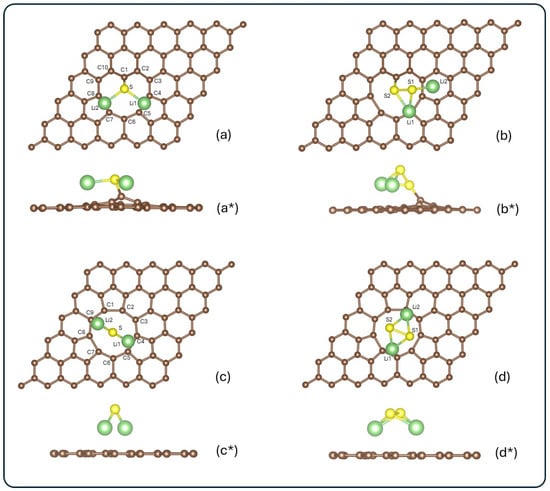
Figure 2.
Top and side views of the optimized configurations for the systems: (a,a*) Li2S@3V-graphene, (b,b*) Li2S2@3V-graphene, (c,c*) Li2S@4V-graphene, and (d,d*) Li2S2@4V-graphene. Carbon, lithium, and sulfur atoms are shown in brown, green, and yellow, respectively. Atoms surrounding the vacancy and those in the adsorbate are labeled for further analysis.
For the Li2S molecule adsorbed on 3V-graphene (see Figure 2a,a*), five different initial configurations were explored. It is noteworthy that all five initial configurations converged to the same final geometry after relaxation. This finding suggests a strong preference for this particular adsorption mode. The calculated adsorption energy for this configuration was −3.84 eV, suggesting a stable interaction between Li2S and the defective graphene surface. In the case of Li2S2 adsorption on 3V-graphene (see Figure 2b,b*), the most stable configuration was found to have an adsorption energy of −1.63 eV. These systems demonstrate enhanced stability in comparison to Li2S and Li2S2 adsorbed on a single vacancy graphene [55]. In both configurations, it is evident that the sulfur attached to the carbon is the geometry preferred by the systems, as illustrated in Figure 2a,b*. The formation of three adjacent vacancies within the graphene lattice gives rise to a sub-coordinated carbon atom, functioning as a coordinatively unsaturated center. A similar behavior was observed with a single vacancy, which also presents a C atom with a dangling bond [55], but with a lower energy interaction, as was previously mentioned. This lower coordinated C atom is a preferential active site for the adsorption of molecules. It is clear that, for both sulfides, the final configurations do not exhibit any magnetic moment. Our calculated binding energy of −3.84 eV (Li2S@3V-graphene) is high and useful because the most significant challenge in Li–S cells is the instantaneous dissolution of lithium polysulfides into the electrolyte. The strong chemisorption is designed to counteract this initial dissolution. Furthermore, the conversion of polysulfides (Li2Sx) to Li2S is a multi-step catalytic process. By achieving strong binding, our material effectively localizes the reaction intermediates to the cathode surface. We hypothesize that the strong interaction itself facilitates the bond cleavage (S–S bond dissociation) necessary for the subsequent reduction, which is a key part of the catalytic mechanism.
Regarding 4V-graphene, Li2S adsorption was tested in a variety of initial configurations, resulting in an adsorption energy of −2.83 eV in the most stable arrangement. This configuration exhibited a preference of lithium atoms to bond to carbons in graphene, as can be seen in Figure 2c,c*. It is important to note that alternative initial configurations resulted in final geometries with higher energies, suggesting their reduced stability. A comparable outcome was observed in the adsorption of Li2S2 on 4V-graphene, resulting in an Eads of −1.51 eV in the most stable configuration. In this case, the Li2S molecule is less stable than the same molecule on single-vacancy graphene. In contrast, the Li2S2 molecule is more stable in 4V-graphene than in single-vacancy graphene [55]. However, 4V-graphene exhibits a higher adsorption energy for both molecules (Li2S and Li2S2) than pristine graphene [55]. As illustrated in Figure 1d,d*, this molecule also exhibits a preference for aligning lithium atoms with the graphene rather than the sulfur atoms. As in each system, alternative initial configurations led to higher-energy final states, confirming the preference for the reported stable configuration. Additionally, a magnetic moment of 0.878 μB was observed for Li2S absorbed onto 3V-graphene, while 0.944 μB was the magnetic moment obtained in the system Li2S2@4V-graphene.
The negative values of Eads indicate that the adsorption process is exothermic and energetically favorable. The variation in Eads values across different configurations and defects highlights the impact of vacancy size and adsorbate orientation on adsorption stability.
The geometrical modifications induced by adsorption were analyzed by comparing the atomic positions before and after interaction. Figure 3 illustrates the changes in optimized structures for each system. The bond lengths between lithium, sulfur, and carbon atoms are colored red for contracted bonds and green for elongated ones.
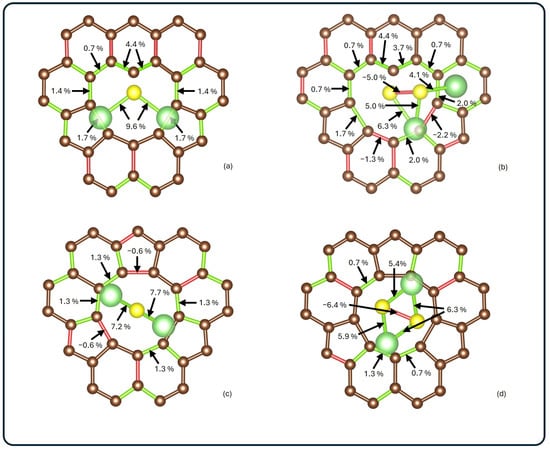
Figure 3.
Schematic visualization of bond length changes for (a) Li2S@3V-graphene, (b) Li2S2@3V-graphene, (c) Li2S@4V-graphene, and (d) Li2S2@4V-graphene. Elongated bonds are shown in green, while contracted ones are shown in red. Bond length changes on the adsorbate and around the poly-vacancy are presented as percentage deviations with respect to the corresponding isolated systems.
Significant distortions were observed in Li2S2 in both analyzed systems, with a contraction between sulfurs of 0.11 Å and 0.14 Å, for 3V-graphene and 4V-graphene, respectively. In addition, it was observed that, in all of the analyzed systems, the Li–S bonds elongate after adsorption, with the largest elongation found for Li2S@3V-graphene, where the change was 0.2 Å. Moreover, it was noted that, for 3V-graphene, the interaction between S and the undercoordinated C results in a significant local lattice distortion of the bond lengths of neighboring carbons (see Figure 3a,b). The most significant increases are observed between the uncoordinated carbon and its first neighbors (0.05 Å and 0.06 Å, respectively). As shown in Figure 2c,d, the carbon atoms adjacent to the vacancy did not undergo significant distortions, showing contractions of 0.01 Å and elongations of up to 0.02 Å.
When the adsorbates are analyzed, notable distortions are observed. In the Li2S@3V-graphene system, Li2S exhibits bond elongations of 0.20 Å, while elongations of 0.15 Å and 0.14 Å are observed when adsorbed on 4V-graphene, as shown in Figure 3a,c. When Li2S2 is adsorbed, a similar effect is observed between Li and S atoms with elongations ranging from 0.09 Å to 0.14 Å. Additionally, contractions of 0.11 Å and 0.14 Å are identified between sulfur atoms in 3V-graphene and 4V-graphene, respectively. Finally, as illustrated in Figure 2b,b*, the Li2S2 molecule undergoes a noticeable distortion, resulting in the Li atom attached to the C atom moving away from one S atom from a distance of 2.22 Å to 3.13 Å.
As illustrated in Figure 2b,b*, the Li2S2 molecule undergoes a significant distortion, resulting in the Li atom attaching to the C atom moving away from one S atom. This movement increases the distance from 2.22 Å to 3.13 Å. Please note that this distance is not shown in Figure 3 because the bond disappears.
3.2. Electronic Structure
3.2.1. Charge Transfer Analysis and ELF Analysis
To quantify the charge redistribution, a Bader charge analysis was performed. The results are summarized in Figure 4, where each atom is colored according to the change in its charge state: the more saturated the blue (red) color, the greater the increase (decrease) in charge.
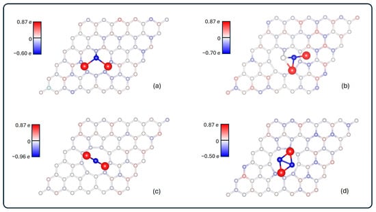
Figure 4.
Charge transfer between atoms. More saturated colors represent greater charge transfer: blue and red indicate negatively or positively charged atoms, respectively. It is shown for (a) Li2S@3V-graphene, (b) Li2S2@3V-graphene, (c) Li2S@4V-graphene, and (d) Li2S2@4V-graphene. The bars on the left are in e unit.
In all of the systems that were analyzed, the charge rearrangement in the graphene is distributed throughout the lattice. There is a notable alternation between positively and negatively charged carbons. This pattern is not perfect, as evidenced by the visible breakage around the multivacancy boundary, attributable to the presence of the adsorbate.
With respect to the charge transfer, lithium sulfides are the primary affected regions. A net charge transfer from the lithium atoms to the graphene substrate is observed, thereby reinforcing the ionic nature of the interaction. The S atoms ended with large negative charges in each system, except for the one closest to the graphene in Li2S2@3V-graphene, whose charge is −0.01 e. For the rest of the sulfurs, the charge ranges from −0.90 e to −0.50 e. On the other hand, focusing on the lithium atoms, the ionization was +0.87 e each, regardless of the system analyzed.
As outlined in Table 2, the final charge state for each system is presented. This includes the ring of carbon’s first neighbors to the vacancy, the total graphene charge of the cell, and the charge of the sulfide. It can be seen that the sulfides end up positively charged in each case, and the change is more than 1 e larger when they are adsorbed in 3V-graphene. For 4V-graphene, the transferred charge is approximately 0.7 e. Additionally, when focusing on the carbon atoms, it is observed that, for Li2S@3V-graphene, Li2S2@3V-graphene, and Li2S2@4V-graphene, the majority of the transferred charge is located in the carbon ring nearest to the vacancy. In the case of Li2S@4V-graphene, the ring concentrates more negative charge than the whole adsorbate.
Table 2.
Transferred charge for each analyzed system, grouped by the carbon ring nearest to the vacancy, the graphene sheet, and the respective sulfide adsorbed.
The charge density difference isosurfaces of the systems are shown in Figure 5.
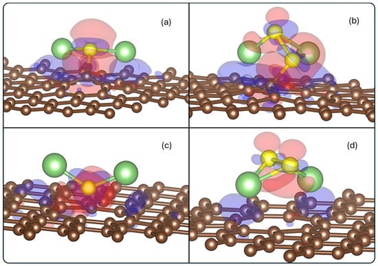
Figure 5.
Charge density difference for (a) Li2S@3V-graphene, (b) Li2S2@3V-graphene, (c) Li2S@4V-graphene, and (d) Li2S2@4V-graphene. Red and blue lobes indicate depletion and accumulation regions of electronics density, respectively. The isosurface value used is 0.02 eÅ−3.
The accumulation of negative charge is observed around the vacancy defect region, with a general electron depletion surrounding the molecule. This finding aligns with the Bader results, which demonstrate a transfer from the molecule to the substrate. It is evident that electron accumulation is observed in the Li2S@3V-graphene and Li2S2@3V-graphene structures, specifically between the S and S2 atoms, respectively, and the C1 carbon atom, which possesses dangling bonds. Therefore, the S–C1 and S2–C1 pair of atoms share electrons, a feature that confers upon them a significant covalent character. Additionally, the S2 atom of Li2S2@3V-graphene is surrounded by accumulation and depletion zones, which explains its Bader neutral charge. In contrast, the S of Li2S@3V-graphene is predominantly negative. The results for the Li2S@4V-graphene and Li2S2@4V-graphene show a similar depletion region behavior, mostly in the molecule, and accumulations in the graphene defect, but in lower magnitude. This is to be expected since the charge transfer between the molecule and 4V-graphene is lower than for 3V-graphene.
The ELF value isosurfaces were plotted in Figure 6, to show the likelihood of finding two electrons.
Figure 6.
ELF for (a) Li2S@3V-graphene, (b) Li2S2@3V-graphene, (c) Li2S@4V-graphene, and (d) Li2S2@4V-graphene side and top views. The isosurface value used is 0.55.
It is observed that there are appreciable ELF values between the C1 and S atoms for the Li2S@3V-graphene and Li2S2@3V-graphene structures, denoting covalent bonds between these atoms. The ELF value around Li atoms is negligible at this isovalue, implying there are positively charged, and the interaction can occur with the C atom of the defects that are negatively charged (the ELF value is significant), forming, in this case, a more ionic character to bond between Li and C atoms in all the systems. Another aspect is that S atoms remain negatively charged in general as was obtained from the Bader analysis.
3.2.2. Density of States and COPH Analysis
The electronic properties of the clean and adsorbed systems were studied through the TDOS and PDOS plots presented in Figure 7.
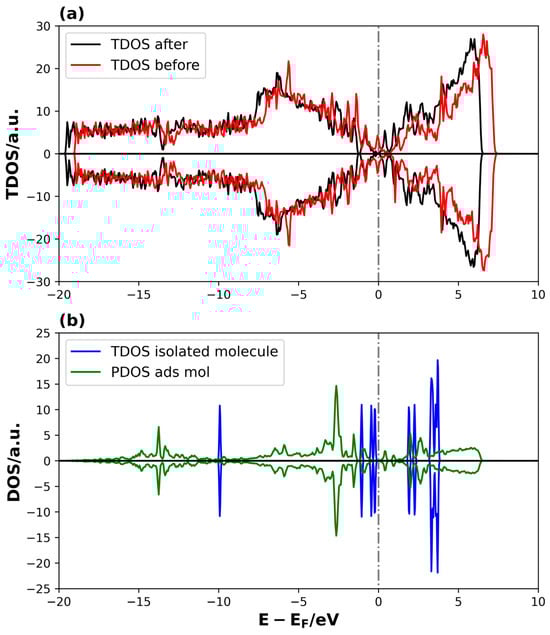
Figure 7.
TDOS and PDOS on Li2S @3V-graphene system: (a) TDOS of 3V-graphene before and after the Li2S adsorption and (b) TDOS of PDOS of isolated and adsorbed Li2S molecule, respectively. The dotted lines represent the Fermi level.
The TDOS curves in Figure 7a demonstrate that changes in the electronic structure occur in specific energy ranges upon adsorption. It is worth noting that the increase in states is observed near the Fermi level, indicating an interaction between the adsorbate and the defected graphene. A comparison of the TDOS of the isolated molecule with the density of states projected on the adsorbed molecule reveals a shift in the energies of the adsorbed Li2S states towards lower values, indicating a stabilization of the molecule through adsorption. In addition, the distribution of adsorbed molecule states between −17 and −1 eV, as compared to the more localized distribution of states in energy for the isolated molecule, suggests a significant degree of interaction strength between Li2S and the defective graphene.
Figure 8 shows the DOS of the 4V-graphene system with and without the Li2S molecule.
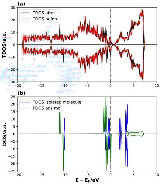
Figure 8.
TDOS and PDOS on Li2S@4V-graphene system: (a) TDOS of 4V-graphene before and after the Li2S adsorption and (b) TDOS of PDOS of isolated and adsorbed Li2S molecule, respectively. The dotted lines represent the Fermi level.
In this case, the differences between the TDOS of the Li2S@4V-graphene and 4V-graphene systems are not very evident, except for two new peaks around −10 eV and the modification of peaks between −2.5 and 0 eV (see Figure 8a). Additionally, distinctive features emerge in the conduction band following adsorption. With regard to the PDOS of the adsorbed Li2S, the pattern related to the shift to lower energies relative to the isolated molecule states is evident, indicating stabilization. However, in this instance, the localized behavior of the molecule remains consistent after adsorption, indicating a potential reduction in the strength of the interaction between the molecule and the 4V-graphene (see Figure 8b). These electronic structure results are consistent with the adsorption energies obtained previously in Table 1, indicating that the Li2S binding strength is higher on 3V-graphene than on 4V-graphene, as determined by their adsorption energies. In addition, a unique aspect of the PDOS of the adsorbed Li2S on the 4V-graphene is the breakdown of symmetry in the spin-up and spin-down states, resulting in the system’s magnetization. The emergence of magnetism in the 4V systems arises from localized unpaired electrons (spin polarization) primarily residing on C atoms around the defect site. These unpaired electrons act as highly active radical sites that can significantly lower the activation energy for the cleavage of the S–S bonds in the lithium polysulfide intermediates (Li2Sx). This mechanism is known to accelerate the sluggish kinetics of the solid-state conversion reaction (Li2S2→Li2S) [68].
A similar analysis can be performed for the adsorption of Li2S2 on 3V-graphene and 4V-graphene, which are shown in the Supplementary Material (Figures S1 and S2, respectively). Once more, a significant intensity and general shifts to lower energies for the valence and conductance bands can be observed in certain energy ranges for the TDOS of the adsorbate + substrate system compared to the substrate TDOS (see Figures S1a and S2a). Furthermore, the projected states for the adsorbed Li2S2 molecule are dispersed and shifted to more negative energies with respect to the isolated molecule’s molecular orbitals on 3V-graphene (see Figure S1b). For 4V-graphene, the adsorbed Li2S2 states also shift towards negative energies, but with a more localized behavior, indicating a stabilization in a lower amount (see Figure S2b). Additionally, this system displays differences in the behavior of the spin-up and spin-down states, leading to the occurrence of spin polarization. Furthermore, the PDOS of Li and S atoms in proximity to the surface, along with the C surface atoms in their vicinity, were analyzed in Figure 9 and Figure 10 to gain a more comprehensive understanding of the formed bonds on Li2S@3V-graphene. Please refer to Figure 2 for the labels of the atoms used in this analysis.
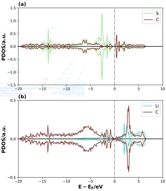
Figure 9.
PDOS of Li2S@3V-graphene system on (a) S and C1 and (b) Li1 and C5. The dotted lines represent the Fermi level.
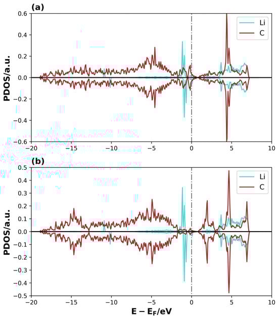
Figure 10.
PDOS of Li2S@4V-graphene system on (a) Li1 and C5, and (b) Li2 and C9. The dotted lines represent the Fermi level.
The overlap between the S atomic orbital states of Li2S and the C1 of graphene is clearly observed in the region close to the Fermi level and at lower energies, forming overlapping peaks in the Li2S@3V-graphene system (see Figure 9a). The C1 atom has a coordination two, and, as a result, it contains sp2 dangling orbitals. These orbitals are free to interact with the atomic orbitals of the molecule [43,48,49]. This is evidenced when we observed that the S atom states are well-dispersed until −17 eV below the Fermi level instead of having a localized behavior as expected for the molecule’s states, meaning that the S–C bond is strong. Additionally, the Li atoms interact with the closer C atoms of the perimeter of the vacancy defect at the bridge sites. As illustrated in Figure 9b, one of these interactions is depicted, where the Li1 atomic orbitals overlap with C4 and C5 atomic orbitals (C atoms belonging to the bridge site). Only the orbitals of the C5 atom are shown, as the C4 atom exhibits equivalent behavior. Please find below the relevant details for your records. An equivalent trend is evident in the Li2, C7, and C8 atomic orbitals, highlighting the symmetry of the molecule’s disposition on the adsorption site, with similar bonds between the Li atom over the bridge sites of the pentagon rings on both sides of the defective region. There are three main overlapped peaks close to the Fermi level, but, this time, the energy dispersion extends approximately up to −7.5 eV. Nevertheless, the Li–C interactions on these bridge sites form other chemical bonds, thereby functioning as points where the molecule attaches to the substrate. Then, for the system Li2S@4V-graphene, Figure 10a shows that Li1 atomic orbitals interact with C4 and C5 atomic orbitals (only C5 PDOS is shown because the projected states for C4 atomic orbitals are equivalent). In this regard, the geometry is helpful because Li is located on the bridge site of these carbon atoms that belong to the pentagon around the defect. The majority of the overlapped peaks between the Li and C projected states occur between −2.5 and 0 eV. This provides a localized character to the Li orbitals, which can be related to a lower overlap with carbon orbitals. This indicates that the strength of the Li and C is lower than that detected on Li2S@3V-graphene between the Li and C atoms. It is important to note that the Li states for spin-up and spin-down exhibit differences. Specifically, the peaks for spin-up are shifted in energy compared to the peaks for spin-down, resulting in a magnetic moment for the Li atom. This effect was not observed in the Li2S@3V-graphene system, but it occurs in the Li2S@4V-graphene system, apparently due to the molecule interacting with a graphene defect. Additionally, there is an overlap between Li2 atomic orbitals and C9 atomic orbitals. In this case, the site can be described as Li on top of a C atom. It is important to note that the overlapping of atomic orbitals occurs within the energy range of −2.5 to 0 eV, accompanied by spin polarization.
A similar analysis was conducted for the systems Li2S2@3V-graphene and Li2S2@4V-graphene, based on the PDOS curves plots shown in Figures S3 and S4. According to these results, we can conclude that there is a significant contribution from the valence band states. This determination is based on the analysis of the previous criteria and the observation of the substantial overlap between the S atomic orbital and the C1 atomic orbital. This overlap is evident in the energy range between −0.5 and −17 eV for Li2S2@3V-graphene, as illustrated in Figure S3a. As shown in Figure S3b, the overlapping between the atomic orbitals for Li1 atoms on C5 atoms is observed mainly up to −7.5 eV below the Fermi level, and the Li atomic orbital energy is dispersed in the same energy range in the valence band. It should be noted that a similar behavior can be demonstrated for Li2 and C3, although these results are not shown in the figure. However, the orbital states for the latter contain other features, likely because the adsorption site is different. Li1 is on top of C5, belonging to a pentagon ring, and the bond distance is 2.16 Å. Li2 is close to a hollow site on a hexagon ring, with a bond distance of 2.21 Å to C3. Figure S4a,b illustrate that the Li and C atomic orbitals exhibit overlapping peaks at different energies within the range of −5 and 0 eV. These peaks are positioned between the Li1 and C2 atomic orbitals in Figure S4a and the Li2 and C7 atomic orbitals in Figure S4b. The orbital states exhibit distinct behaviors for spin-up and spin-down, indicating that the Li and C atoms contribute to the magnetization of the Li2S2@4V-graphene, with a significant contribution from the Li states.
3.3. Bond Order and Interaction Strength
The bond order calculations provide further insight into the interaction strength between the adsorbates and the defective graphene. Table 3 and Table 4 summarize the Li–S, S–S, and S–C bond order values, before and after adsorption for each system. Significant changes after adsorption are an indication of new chemical interactions.
Table 3.
Bond order values of Li2S, Li2S2, and 3V-graphene before and after adsorption, with the respective percentage change (% Δ). The atoms are labeled according to Figure 2. Changes lower than 4% were omitted.
Table 4.
Bond order values of Li2S, Li2S2, and 4V-graphene before and after adsorption, with the respective percentage change (% Δ). The atoms are labeled according to Figure 2. Changes lower than 4% are omitted.
As shown in Table 3, the interaction between Li and S weakens after adsorption, indicating a BO change of over 50% for the Li2S@3V-graphene system. A similar situation occurs between C1 and its first neighbors, with a decrease of 21%. On the other hand, the interaction between C1 and S reaches a value of 1.244, which can be interpreted as a strong interaction. Focusing on the Li2S2@3V-graphene system, it is evident that the interaction between the adsorbate and the support is weaker. Nonetheless, the geometric change in Li2S2 generates a bond order (BO) change between S2 and Li2 of −98%, revealing a bond break between them.
A similar analysis can be carried out for the Li2S@4V-graphene and Li2S2@4V-graphene systems, as shown in Table 4. The main difference lies in the absence of an undercoordinated carbon atom and its tendency to attach to the adsorbates. This approach produces weaker interactions between the graphene and the sulfides. However, a bond order decrease between sulfur and lithium atoms is still observed. Similar tendencies were observed with the overlap population, as reported in the Supplementary Material in Tables S1 and S2.
In addition, in Figure 11 and Figure 12 are shown the pCOHP curves for the bonds through the pair of atoms analyzed previously in the PDOS results. These curves aid us in comprehending the contribution of these bonds to the total electronic energy, allowing the visualization of bonding (negative curves) and antibonding (positive curves) interactions. Furthermore, the ICOPH was included to indicate the strength of the chemical bond between the specified atoms, delivering a quantitative measure of bonding energy.
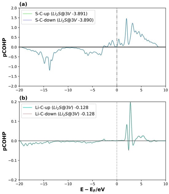
Figure 11.
pCOHP of Li2S@3V-graphene system on interactions between (a) S and C1 and (b) Li1 and C5, for spin-up and spin-down. The number of the legend represents its ICOHP. The dotted lines represent the Fermi level.
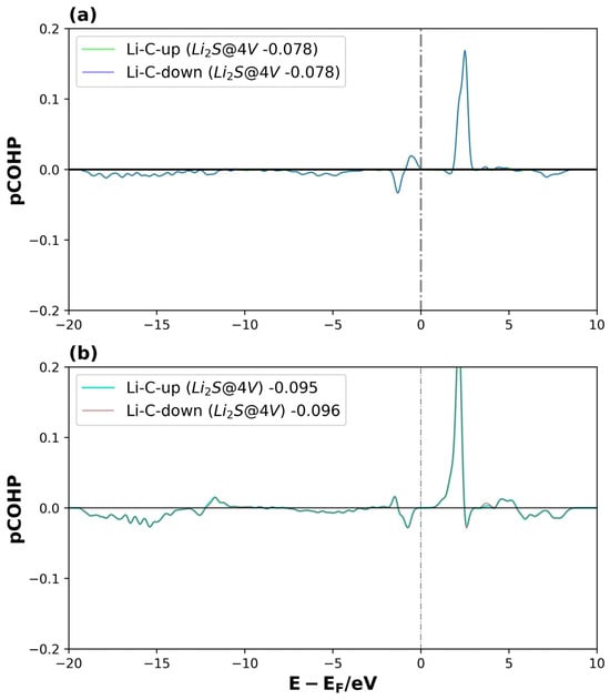
Figure 12.
pCOHP of Li2S@4V-graphene system on interactions between (a) Li1 and C5, and (b) Li2 and C9., for spin-up and spin-down. The number of the legend represents its ICOHP. The dotted lines represent the Fermi level.
For Li2S@3V-graphene (see Figure 11a,b), bonding orbitals between the S and C1 atomic orbitals are observed around −15 eV and −5 eV, while antibonding orbitals appear near the Fermi level. However, the bonding contribution is considerably greater. For the Li–C interaction, the bonding states are distributed between −20 and −5 eV, but with a lower intensity, showing only small negative peaks that indicate a weaker interaction. The ICOHP values confirm this observation: the S–C1 interaction (−3.89) is significantly stronger (i.e., more negative) compared to the Li1–C5 bond (−0.13). The same behavior is observed for both spin channels, as expected for a non-magnetized system. These results partially explain the higher adsorption energy found for graphene with three vacancies, where the carbon atom with dangling bonds (C1) plays a crucial role in contributing to the total electronic energy. Similar results were obtained for Li2S2@3V-graphene (see Figure S5 in the Supplementary Material).
For Li2S@4V-graphene (see Figure 12a,b), the bond strengths of the Li1–C5 and Li2–C9 interactions are comparable according to their ICOHP values. The main difference lies in the energy distribution of the bonding and antibonding orbitals. Despite the fact that Li2S@4V-graphene is a magnetized system, the Li–C bonds are not directly related to the system’s spin polarization, showing a similar behavior for both the spin-up and spin-down states. A similar trend is observed for Li2S2@4V-graphene (see Figure S6), with the exception that, in this case, a slight difference appears in the spin-up and spin-down components of the bonding and antibonding orbitals of the Li1–C7 and Li2–C2 interactions at energies close to −13 eV. Nevertheless, this difference barely affects the ICOHP values for both spins. Moreover, the ICOHP values for Li2S@4V-graphene and Li2S2@4V-graphene range between −0.08 and −0.10, and −0.13 and −0.14, respectively, indicating that the Li–C bond contributes to the total electronic energy of the system, but with a magnitude comparable to that of the Li–C interaction in Li2S@3V-graphene. Consequently, these findings reinforce the idea that the uncoordinated carbon atom in 3V-graphene is essential for the high stability of these systems, while the Li–C interaction provides only a minor contribution.
This study’s focus on short-chain Li2S2 and the final product Li2S distinguishes our approach from conventional strategies that solely target the highly soluble, long-chain polysulfides (Li2Sx, x = 4, 6, 8)—the primary drivers of the shuttle effect’s diffusion [21]. While trapping these mobile species is a valid approach, our investigation addresses the kinetic and confinement bottlenecks that are equally detrimental to battery life. Li2S is the most critical rate-limiting step during charging, and its efficient nucleation and decomposition are paramount for achieving a high capacity and stable cycling [69]. Conversely, Li2S2 acts as the crucial transition bridge between the soluble intermediates and the solid final product [70]. Therefore, our core strategy is not direct long-chain trapping in the electrolyte, but rather accelerating the final conversion and anchoring the Li2S2 to Li2S at the cathode surface. By substantially improving the interfacial properties of these two compounds, we effectively force the mobile intermediates to rapidly reduce into reversible solid products within the cathode’s porous structure, achieving a powerful, indirect mitigation of the shuttle effect while simultaneously ensuring efficient sulfur utilization and enhanced cathode integrity. The detailed investigation into the role of highly soluble long-chain polysulfides (Li2Sx with x = 4, 6, 8) in the shuttle effect will be the focus of a subsequent study.
4. Conclusions
This research has shown that low-molecular-weight lithium sulfide molecules, Li2S and Li2S2, are found to be stable when they are adsorbed on vacancy-defected graphene. The most stable system corresponds to the Li2S molecule adsorbed on 3V-graphene. In this substrate, the role of the carbon atom with a dangling bond is crucial for the adsorption process. This atom functions as an active center, attracting S atoms. In this case, the C–S bond’s strength is notable, particularly in the Li2S2 molecule. This bond strengthens through the formation of overlapping C and S atomic orbitals, which are dispersed evenly in energy. In the 4V-graphene systems, the interaction of the molecules is reduced due to the overlap between the Li and C atomic orbitals. Furthermore, the states in these last systems are mainly spin-polarized due to the non-symmetrical Li atomic states, resulting in their magnetization.
All the systems display a dispersion of the projected states for adsorbed molecules and a shift towards lower energies compared to the states of isolated molecules. This effect leads to a stabilization of the adsorbed systems, which is also compatible with more exothermic adsorption energy. This process involves a significant charge transfer from the molecule to the substrate, ranging from 0.7 e to 1 e, which is predominantly concentrated within the defect perimeter, ranging from 70% to 100%. This charge transfer is more pronounced for the 3V-graphene sample. Additionally, the Li–S bond weakens after adsorption, but the molecular structure is maintained due to the preservation of the bond. Furthermore, the interaction of the molecule and the substrate defect leads to a general stretch of C–C bonds around the defect.
These results provide a systematic study and a solid foundation for understanding the main mechanisms that occur between lithium–sulfur molecules and vacancy-defected graphene. This knowledge is essential for the further study of these carbon structures, particularly their ability to adsorb polysulfides.
The present study has demonstrated the efficacy of multivacancy defects in graphene as anchoring sites for lithium sulfides. A more realistic model must include long-chain polysulfides, incorporate a more realistic electrolyte environment, and supplement the thermodynamic analysis with an investigation into the kinetics of electrochemical conversion. This will be the subject of a future research project that would transition from a fundamental exploration of chemical bonding to a more direct and powerful guide for designing next-generation cathode hosts for Li–S batteries.
Supplementary Materials
The following supporting information can be downloaded at: https://www.mdpi.com/article/10.3390/surfaces8040076/s1, Figure S1: TDOS and PDOS on Li2S2@3V-graphene system; Figure S2: TDOS and PDOS on Li2S2@4V-graphene system; Figure S3: PDOS of Li2S2@3V-graphene system on (a) S2 and C1, and (b) Li1 and C5; Figure S4: PDOS of Li2S2@4V-graphene system on (a) Li1 and C7, and (b) Li2 and C2; Figure S5: pCOHP of Li2S2@3V-graphene system on interactions between (a) S2 and C1, and (b) Li1 and C5, for spin-up and spin-down; Figure S6: pCOHP of Li2S2@4V-graphene system on interactions between (a) Li1 and C7, and (b) Li2 and C2, for spin-up and spin-down; Table S1: Overlap population values of Li2S, Li2S2, and 3V-graphene before and after adsorption, with the respective percentage change (% Δ); Table S2: Overlap population values of Li2S, Li2S2, and 4V-graphene before and after adsorption, with the respective percentage change (% Δ).
Author Contributions
Conceptualization, F.G. and R.E.A.; methodology, F.G. and R.E.A.; software, F.G. and R.E.A.; validation, F.G. and R.E.A.; formal analysis, F.G. and R.E.A.; investigation, F.G., R.E.A., and A.J.; resources, A.J. and G.P.B.; writing—original draft preparation, F.G. and R.E.A.; writing—review and editing, F.G., R.E.A., A.J., and G.P.B.; visualization, F.G. and R.E.A.; supervision, R.E.A. and A.J.; project administration, A.J. and G.P.B.; funding acquisition, A.J. and G.P.B. All authors have read and agreed to the published version of the manuscript.
Funding
This research was funded by Universidad Nacional del Sur (UNS), grant number PGI-UNS 24/F083, and by ANPCyT, grant number PICT-2019-3491, PICT-2021-I-A-01144, PICT 2022-01-00049, and EU Funded project NANOTRIOSTEO HORIZON-MSCA-2023-SE-01, project number 101182658.
Data Availability Statement
Data acquisition will be provided under request.
Acknowledgments
The simulations were performed on the Computer Cluster provided by IFISUR-CONICET, Argentina. REA, GPB, and AJ are members of IFISUR-CONICET. FG is a fellow researcher at IFISUR-CONICET. All authors have given approval to the final version of the manuscript.
Conflicts of Interest
The authors declare no conflicts of interest.
Abbreviations
The following abbreviations are used in this manuscript:
| ANPCyT | Agencia Nacional de Promoción de Científica y Tecnológica |
| CONICET | Consejo Nacional de Investigaciones Científicas y Técnicas |
References
- Ji, X.; Nazar, L.F. Advances in Li–S Batteries. J. Mater. Chem. 2010, 20, 9821–9826. [Google Scholar] [CrossRef]
- Bruce, P.G.; Freunberger, S.A.; Hardwick, L.J.; Tarascon, J.-M. Li–O2 and Li–S Batteries with High Energy Storage. Nat. Mater. 2012, 11, 19–29. [Google Scholar] [CrossRef]
- Manthiram, A.; Fu, Y.; Su, Y.-S. Challenges and Prospects of Lithium–Sulfur Batteries. Acc. Chem. Res. 2013, 46, 1125–1134. [Google Scholar] [CrossRef] [PubMed]
- Ding, B.; Wang, J.; Fan, Z.; Chen, S.; Lin, Q.; Lu, X.; Dou, H.; Kumar Nanjundan, A.; Yushin, G.; Zhang, X.; et al. Solid-State Lithium–Sulfur Batteries: Advances, Challenges and Perspectives. Mater. Today 2020, 40, 114–131. [Google Scholar] [CrossRef]
- Zhao, M.; Li, B.; Peng, H.; Yuan, H.; Wei, J.; Huang, J. Lithium–Sulfur Batteries under Lean Electrolyte Conditions: Challenges and Opportunities. Angew. Chem. Int. Ed. 2020, 59, 12636–12652. [Google Scholar] [CrossRef] [PubMed]
- Hou, L.-P.; Zhang, X.-Q.; Li, B.-Q.; Zhang, Q. Challenges and Promises of Lithium Metal Anode by Soluble Polysulfides in Practical Lithium–Sulfur Batteries. Mater. Today 2021, 45, 62–76. [Google Scholar] [CrossRef]
- Deshmukh, A.; Thripuranthaka, M.; Chaturvedi, V.; Das, A.K.; Shelke, V.; Shelke, M.V. A Review on Recent Advancements in Solid State Lithium–Sulfur Batteries: Fundamentals, Challenges, and Perspectives. Prog. Energy 2022, 4, 042001. [Google Scholar] [CrossRef]
- Raza, H.; Bai, S.; Cheng, J.; Majumder, S.; Zhu, H.; Liu, Q.; Zheng, G.; Li, X.; Chen, G. Li-S Batteries: Challenges, Achievements and Opportunities. Electrochem. Energy Rev. 2023, 6, 29. [Google Scholar] [CrossRef]
- Lv, Z.-C.; Wang, P.-F.; Wang, J.-C.; Tian, S.-H.; Yi, T.-F. Key Challenges, Recent Advances and Future Perspectives of Rechargeable Lithium-Sulfur Batteries. J. Ind. Eng. Chem. 2023, 124, 68–88. [Google Scholar] [CrossRef]
- Liu, Y.; Qin, T.; Wang, P.; Yuan, M.; Li, Q.; Feng, S. Challenges and Solutions for Low-Temperature Lithium–Sulfur Batteries: A Review. Materials 2023, 16, 4359. [Google Scholar] [CrossRef]
- Shao, Q.; Zhu, S.; Chen, J. A Review on Lithium-Sulfur Batteries: Challenge, Development, and Perspective. Nano Res. 2023, 16, 8097–8138. [Google Scholar] [CrossRef]
- Jiao, Y.; Wang, F.; Ma, Y.; Luo, S.; Li, Y.; Hu, A.; He, M.; Li, F.; Chen, D.; Chen, W.; et al. Challenges and Advances on Low-Temperature Rechargeable Lithium-Sulfur Batteries. Nano Res. 2023, 16, 8082–8096. [Google Scholar] [CrossRef]
- Shi, H.; Sun, W.; Cao, J.; Han, S.; Lu, G.; Ghazi, Z.A.; Zhu, X.; Lan, H.; Lv, W. Challenges and Solutions for Lithium–Sulfur Batteries with Lean Electrolyte. Adv. Funct. Mater. 2023, 33, 2306933. [Google Scholar] [CrossRef]
- Pathak, A.D.; Cha, E.; Choi, W. Towards the Commercialization of Li-S Battery: From Lab to Industry. Energy Storage Mater. 2024, 72, 103711. [Google Scholar] [CrossRef]
- Qian, W.; Guo, Y.; Zuo, W.; Wu, X.; Zhang, L. Toward Practical Lithium–Sulfur Batteries. Mater. Chem. Front. 2024, 8, 2556–2577. [Google Scholar] [CrossRef]
- Sawangphruk, M. New Materials for Lithium–Sulfur Batteries: Challenges and Future Directions. Chem. Commun. 2025, 61, 7770–7794. [Google Scholar] [CrossRef]
- Sharma, R.; Kumar, H.; Kumar, G.; Sharma, S.; Aneja, R.; Sharma, A.K.; Kumar, R.; Kumar, P. Progress and Challenges in Electrochemical Energy Storage Devices: Fabrication, Electrode Material, and Economic Aspects. Chem. Eng. J. 2023, 468, 143706. [Google Scholar] [CrossRef]
- Wang, H.; Yang, Y.; Liang, Y.; Robinson, J.T.; Li, Y.; Jackson, A.; Cui, Y.; Dai, H. Graphene-Wrapped Sulfur Particles as a Rechargeable Lithium–Sulfur Battery Cathode Material with High Capacity and Cycling Stability. Nano Lett. 2011, 11, 2644–2647. [Google Scholar] [CrossRef]
- Zhou, G.; Pei, S.; Li, L.; Wang, D.; Wang, S.; Huang, K.; Yin, L.; Li, F.; Cheng, H. A Graphene–Pure-Sulfur Sandwich Structure for Ultrafast, Long-Life Lithium–Sulfur Batteries. Adv. Mater. 2014, 26, 625–631. [Google Scholar] [CrossRef]
- Xu, G.; Ding, B.; Pan, J.; Nie, P.; Shen, L.; Zhang, X. High-Performance Lithium–Sulfur Batteries: Advances and Challenges. Small 2015, 11, 4321–4347. [Google Scholar] [CrossRef]
- Ji, X.; Lee, K.T.; Nazar, L.F. A Highly Ordered Nanostructured Carbon–Sulphur Cathode for Lithium–Sulphur Batteries. Nat. Mater. 2009, 8, 500–506. [Google Scholar] [CrossRef]
- Seh, Z.W.; Sun, Y.; Zhang, Q.; Cui, Y. Designing High-Energy Lithium–Sulfur Batteries. Chem. Soc. Rev. 2016, 45, 5605–5634. [Google Scholar] [CrossRef]
- Wang, S.; Qu, C.; Wen, J.; Wang, C.; Ma, X.; Yang, Y.; Huang, G.; Sun, H.; Xu, S. Progress of Transition Metal Sulfides Used as Lithium-Ion Battery Anodes. Mater. Chem. Front. 2023, 7, 2779–2808. [Google Scholar] [CrossRef]
- Liang, X.; Garsuch, A.; Nazar, L.F. Sulfur Cathodes Based on Conductive MXene Nanosheets for High-Performance Lithium–Sulfur Batteries. Angew. Chem. 2015, 127, 3979–3983. [Google Scholar] [CrossRef]
- Suzanowicz, A.; Mei, C.; Mandal, B. Approaches to Combat the Polysulfide Shuttle Phenomenon in Li–S Battery Technology. Batteries 2022, 8, 45. [Google Scholar] [CrossRef]
- Wang, J.; Wang, H.; Jia, S.; Zhao, Q.; Zheng, Q.; Ma, Y.; Ma, T.; Li, X. Recent Advances in Inhibiting Shuttle Effect of Polysulfide in Lithium-Sulfur Batteries. J. Energy Storage 2023, 72, 108372. [Google Scholar] [CrossRef]
- Rao, X.-Y.; Xiang, S.-F.; Zhou, J.; Zhang, Z.; Xu, X.-Y.; Xu, Y.-Y.; Zhou, X.-C.; Pan, Z.-D.; Tan, S.-C.; Dong, S.-X.; et al. Recent Progress and Strategies of Cathodes toward Polysulfides Shuttle Restriction for Lithium-Sulfur Batteries. Rare Met. 2024, 43, 4132–4161. [Google Scholar] [CrossRef]
- Evers, S.; Nazar, L.F. New Approaches for High Energy Density Lithium–Sulfur Battery Cathodes. Acc. Chem. Res. 2013, 46, 1135–1143. [Google Scholar] [CrossRef] [PubMed]
- Pan, H.; Cheng, Z.; He, P.; Zhou, H. A Review of Solid-State Lithium–Sulfur Battery: Ion Transport and Polysulfide Chemistry. Energy Fuels 2020, 34, 11942–11961. [Google Scholar] [CrossRef]
- Yu, M.; Li, R.; Wu, M.; Shi, G. Graphene Materials for Lithium–Sulfur Batteries. Energy Storage Mater. 2015, 1, 51–73. [Google Scholar] [CrossRef]
- Chadha, U.; Bhardwaj, P.; Padmanaban, S.; Suneel, R.M.; Milton, K.; Subair, N.; Pandey, A.; Khanna, M.; Srivastava, D.; Mathew, R.M.; et al. Review—Contemporary Progresses in Carbon-Based Electrode Material in Li-S Batteries. J. Electrochem. Soc. 2022, 169, 020530. [Google Scholar] [CrossRef]
- Liu, Y.; Wei, H.; Zhai, X.; Wang, F.; Ren, X.; Xiong, Y.; Akiyoshi, O.; Pan, K.; Ren, F.; Wei, S. Graphene-Based Interlayer for High-Performance Lithium–Sulfur Batteries: A Review. Mater. Des. 2021, 211, 110171. [Google Scholar] [CrossRef]
- Zhao, Z.; Liu, R.; Tang, R.; Cheng, X.; He, Z.; Meng, T. Insight into the Polysulfides Conversion Kinetics and Its Activation Energy Relationship on Ultrafine V8C7 in Li-S Batteries. Chem. Eng. J. 2024, 500, 156970. [Google Scholar] [CrossRef]
- Rao, D.; Wang, Y.; Zhang, L.; Yao, S.; Qian, X.; Xi, X.; Xiao, K.; Deng, K.; Shen, X.; Lu, R. Mechanism of Polysulfide Immobilization on Defective Graphene Sheets with N-Substitution. Carbon 2016, 110, 207–214. [Google Scholar] [CrossRef]
- Song, J.; Xu, T.; Gordin, M.L.; Zhu, P.; Lv, D.; Jiang, Y.; Chen, Y.; Duan, Y.; Wang, D. Nitrogen-Doped Mesoporous Carbon Promoted Chemical Adsorption of Sulfur and Fabrication of High-Areal-Capacity Sulfur Cathode with Exceptional Cycling Stability for Lithium-Sulfur Batteries. Adv. Funct. Mater. 2014, 24, 1243–1250. [Google Scholar] [CrossRef]
- Zhang, J.; Shi, Y.; Ding, Y.; Zhang, W.; Yu, G. In Situ Reactive Synthesis of Polypyrrole-MnO2 Coaxial Nanotubes as Sulfur Hosts for High-Performance Lithium–Sulfur Battery. Nano Lett. 2016, 16, 7276–7281. [Google Scholar] [CrossRef]
- Zhang, S.; Ueno, K.; Dokko, K.; Watanabe, M. Recent Advances in Electrolytes for Lithium–Sulfur Batteries. Adv. Energy Mater. 2015, 5, 1500117. [Google Scholar] [CrossRef]
- Li, J.; Qu, Y.; Chen, C.; Zhang, X.; Shao, M. Theoretical Investigation on Lithium Polysulfide Adsorption and Conversion for High-Performance Li–S Batteries. Nanoscale 2021, 13, 15–35. [Google Scholar] [CrossRef]
- Yang, X.; Luo, J.; Sun, X. Towards High-Performance Solid-State Li–S Batteries: From Fundamental Understanding to Engineering Design. Chem. Soc. Rev. 2020, 49, 2140–2195. [Google Scholar] [CrossRef]
- Chen, R.; Zhou, Y.; He, J.; Li, X. Advanced Computational Methods in Lithium–Sulfur Batteries. Adv. Funct. Mater. 2024, 34, 2407986. [Google Scholar] [CrossRef]
- Zhang, X.; Li, S.; Wang, Z.; Yan, J.; Liu, J.; Wu, Y. Review on the First-Principles Calculation in Lithium-Sulfur Battery. Prog. Chem. 2023, 35, 375–389. [Google Scholar] [CrossRef]
- Banhart, F.; Kotakoski, J.; Krasheninnikov, A.V. Structural Defects in Graphene. ACS Nano 2011, 5, 26–41. [Google Scholar] [CrossRef]
- Ambrusi, R.E.; Luna, C.R.; Juan, A.; Pronsato, M.E. DFT Study of Rh-Decorated Pristine, B-Doped and Vacancy Defected Graphene for Hydrogen Adsorption. RSC Adv. 2016, 6, 83926–83941. [Google Scholar] [CrossRef]
- Ambrusi, R.E.; Orazi, V.; Morelli, A.; Marchetti, J.M.; Juan, A. Theoretical Study of a Ti4 Cluster Interacting with B-Doped and Non-Doped Multivacancy Graphene. Phys. B Condens. Matter 2024, 683, 415875. [Google Scholar] [CrossRef]
- Ambrusi, R.E.; Orazi, V.; Marchetti, J.M.; Pronsato, M.E. Ni Clusters Embedded in Multivacancy Graphene Substrates. J. Phys. Chem. Solids 2020, 138, 109258. [Google Scholar] [CrossRef]
- Orazi, V.; Ambrusi, R.E.; Marchetti, J.M.; Pronsato, M.E. DFT Study of the Hydrogen Adsorption and Storage on Ni4 Cluster Embedded in Multivacancy Graphene. Int. J. Hydrogen Energy 2020, 45, 30805–30817. [Google Scholar] [CrossRef]
- Ambrusi, R.E.; Orazi, V.; Marchetti, J.M.; Juan, A.; Pronsato, M.E. Hydrogen Storage by Spillover on Ni4 Cluster Embedded in Three Vacancy Graphene. A DFT and Dynamics Study. J. Phys. Chem. Solids 2022, 167, 110706. [Google Scholar] [CrossRef]
- Faccio, R.; Fernández-Werner, L.; Pardo, H.; Goyenola, C.; Ventura, O.N.; Mombrú, A.W. Electronic and Structural Distortions in Graphene Induced by Carbon Vacancies and Boron Doping. J. Phys. Chem. C 2010, 114, 18961–18971. [Google Scholar] [CrossRef]
- Faccio, R.; Mombrú, A.W. Magnetism in Multivacancy Graphene Systems. J. Phys. Condens. Matter 2012, 24, 375304. [Google Scholar] [CrossRef]
- Faccio, R.; Mombrú, A.W. Influence of the Structural Configuration on the Stability and Magnetism in Multivacancy Graphene Systems. Comput. Mater. Sci. 2015, 97, 193–200. [Google Scholar] [CrossRef]
- Mombrú, D.; Faccio, R.; Mombrú, A.W. First Row Transition Metal Atoms Embedded in Multivacancies in a Rippled Graphene System. Appl. Surf. Sci. 2018, 435, 102–107. [Google Scholar] [CrossRef]
- Mombrú, D.; Faccio, R.; Mombrú, A.W. Sulfur Doping in Multivacancy Graphene Systems. Appl. Surf. Sci. 2018, 459, 336–344. [Google Scholar] [CrossRef]
- Rao, D.; Yang, H.; Shen, X.; Yan, X.; Qiao, G. Immobilisation of Sulphur on Cathodes of Lithium–Sulphur Batteries via B-Doped Atomic-Layer Carbon Materials. Phys. Chem. Chem. Phys. 2019, 21, 10895–10901. [Google Scholar] [CrossRef]
- Jyothirmai, M.V.; Ravva, M.K. Changes in Structure and Stability of Lithium Polysulfides Encapsulated in Carbon Nanotubes: A DFT Study. J. Mol. Liq. 2022, 359, 119287. [Google Scholar] [CrossRef]
- Yi, Z.; Su, F.; Huo, L.; Cui, G.; Zhang, C.; Han, P.; Dong, N.; Chen, C. New Insights into Li2S2/Li2S Adsorption on the Graphene Bearing Single Vacancy: A DFT Study. Appl. Surf. Sci. 2020, 503, 144446. [Google Scholar] [CrossRef]
- Kresse, G.; Hafner, J. Ab Initio Molecular Dynamics for Liquid Metals. Phys. Rev. B 1993, 47, 558–561. [Google Scholar] [CrossRef] [PubMed]
- Kresse, G.; Joubert, D. From Ultrasoft Pseudopotentials to the Projector Augmented-Wave Method. Phys. Rev. B 1999, 59, 1758–1775. [Google Scholar] [CrossRef]
- Kresse, G.; Furthmüller, J. Efficiency of Ab-Initio Total Energy Calculations for Metals and Semiconductors Using a Plane-Wave Basis Set. Comput. Mater. Sci. 1996, 6, 15–50. [Google Scholar] [CrossRef]
- Perdew, J.P.; Burke, K.; Ernzerhof, M. Generalized Gradient Approximation Made Simple. Phys. Rev. Lett. 1996, 77, 3865–3868. [Google Scholar] [CrossRef]
- Blöchl, P.E. Projector Augmented-Wave Method. Phys. Rev. B 1994, 50, 17953–17979. [Google Scholar] [CrossRef]
- Grimme, S.; Antony, J.; Ehrlich, S.; Krieg, H. A Consistent and Accurate Ab Initio Parametrization of Density Functional Dispersion Correction (DFT-D) for the 94 Elements H-Pu. J. Chem. Phys. 2010, 132, 154104. [Google Scholar] [CrossRef]
- Monkhorst, H.J.; Pack, J.D. Special Points for Brillouin-Zone Integrations. Phys. Rev. B 1976, 13, 5188–5192. [Google Scholar] [CrossRef]
- Dronskowski, R.; Bloechl, P.E. Crystal Orbital Hamilton Populations (COHP): Energy-Resolved Visualization of Chemical Bonding in Solids Based on Density-Functional Calculations. J. Phys. Chem. 1993, 97, 8617–8624. [Google Scholar] [CrossRef]
- Deringer, V.L.; Tchougréeff, A.L.; Dronskowski, R. Crystal Orbital Hamilton Population (COHP) Analysis as Projected from Plane-Wave Basis Sets. J. Phys. Chem. A 2011, 115, 5461–5466. [Google Scholar] [CrossRef] [PubMed]
- Nelson, R.; Ertural, C.; George, J.; Deringer, V.L.; Hautier, G.; Dronskowski, R. LOBSTER: Local Orbital Projections, Atomic Charges, and Chemical-bonding Analysis from Projector-augmented-wave-based Density-functional Theory. J. Comput. Chem. 2020, 41, 1931–1940. [Google Scholar] [CrossRef] [PubMed]
- Maintz, S.; Deringer, V.L.; Tchougréeff, A.L.; Dronskowski, R. Analytic Projection from Plane-Wave and PAW Wavefunctions and Application to Chemical-Bonding Analysis in Solids. J. Comput. Chem. 2013, 34, 2557–2567. [Google Scholar] [CrossRef] [PubMed]
- Lehtinen, O.; Tsai, I.-L.; Jalil, R.; Nair, R.R.; Keinonen, J.; Kaiser, U.; Grigorieva, I.V. Non-Invasive Transmission Electron Microscopy of Vacancy Defects in Graphene Produced by Ion Irradiation. Nanoscale 2014, 6, 6569–6576. [Google Scholar] [CrossRef]
- Yan, R.; Zhao, Z.; Cheng, M.; Yang, Z.; Cheng, C.; Liu, X.; Yin, B.; Li, S. Origin and Acceleration of Insoluble Li2S2−Li2S Reduction Catalysis in Ferromagnetic Atoms-based Lithium-Sulfur Battery Cathodes. Angew. Chem. 2023, 62, e202215414. [Google Scholar] [CrossRef]
- Zhou, G.; Tian, H.; Jin, Y.; Tao, X.; Liu, B.; Zhang, R.; Seh, Z.W.; Zhuo, D.; Liu, Y.; Sun, J.; et al. Catalytic Oxidation of Li2S on the Surface of Metal Sulfides for Li−S Batteries. Proc. Natl. Acad. Sci. USA 2017, 114, 840–845. [Google Scholar] [CrossRef]
- Yang, G.; Shi, S.; Yang, J.; Ma, Y. Insight into the Role of Li2S2 in Li–S Batteries: A First-Principles Study. J. Mater. Chem. A Mater. 2015, 3, 8865–8869. [Google Scholar] [CrossRef]


Disclaimer/Publisher’s Note: The statements, opinions and data contained in all publications are solely those of the individual author(s) and contributor(s) and not of MDPI and/or the editor(s). MDPI and/or the editor(s) disclaim responsibility for any injury to people or property resulting from any ideas, methods, instructions or products referred to in the content. |
© 2025 by the authors. Licensee MDPI, Basel, Switzerland. This article is an open access article distributed under the terms and conditions of the Creative Commons Attribution (CC BY) license (https://creativecommons.org/licenses/by/4.0/).