Article

Effect of Hydrodynamic Conditions on the Corrosion Mechanism of HSLA X100 Steel by EIS and EN Analysis

by
Ricardo Galván-Martínez
1,
Clarisa Campechano-Lira
1,
Ricardo Orozco-Cruz
1,*,
Miguel Ángel Hernández-Pérez
1,
Francisco López-Huerta
2,
Edgar Mejía-Sánchez
3,
Jorge Alberto Ramírez-Cano
1 and
Andres Carmona-Hernández
1,*
1
Instituto de Ingeniería, Universidad Veracruzana, S. S. Juan Pablo II, Zona Universitaria, Boca del Río 94294, Veracruz, Mexico
2
Facultad de Ingeniería Eléctrica y Electrónica, Universidad Veracruzana, Adolfo Ruiz Cortines No. 455, Fracc. Costa Verde, Boca del Río 94294, Veracruz, Mexico
3
Facultad de Ingeniería, Universidad Veracruzana, KM 1.0 Carretera Sumidero Dos Ríos, Veracruz 94452, Veracruz, Mexico
*
Authors to whom correspondence should be addressed.
Surfaces 2025, 8(1), 10; https://doi.org/10.3390/surfaces8010010
Submission received: 29 November 2024 / Revised: 17 January 2025 / Accepted: 28 January 2025 / Published: 1 February 2025
(This article belongs to the Special Issue Advancements in Surface Engineering for Metallic Alloys)

Abstract

:
In this research work, the influence of the electrolyte hydrodynamic conditions on the corrosion mechanism of the high-strength low-alloy (HSLA) X100 steel used in the petroleum transportation pipelines was analyzed. A Rotary Cylinder Electrode (RCE) was used to simulate the hydrodynamic conditions (1000 and 5000 rpm). Mechanical, microstructural and elemental characterization tests were performed on X100 steel, and the electrochemical impedance spectroscopy (EIS) technique was used to analyze the corrosion mechanism, while the morphology of the corrosion process on the corroded surfaces was obtained by scanning electronic microscopy (SEM). It was found that the increasing rotation rate (υ rot) generates a fully developed flow regime where the system was dominated by a mass transfer process and increases the kinetics of chemical and electrochemical reactions so there is an increase in the corrosion rate (CR). On the other hand, the adsorption of corrosion product films that limits the charge transfer process depended on the magnitude of the shear stress that can generate wear and roughness, as well as a greater number of anodic sites, leaving the metal exposure to the corrosive medium.

Graphical Abstract

1. Introduction

The pipelines are the most feasible and economical way to transport large volumes of crude oil, natural gas and petroleum products over long distances in the oil and gas industry [1,2]. Depending on the corrosivity of transported fluid and external environmental conditions, the extensive stretches of gas and oil transmission pipelines currently in operation are prone to failure by corrosion, among other factors [3]. The pipelines are fabricated from high-strength low-alloy (HSLA) steels, which are characterized by having in their chemical composition a very low carbon percentage. It is important to point out that these steels have small amounts of alloying elements, and these types of steel are classified by the American Petroleum Institute (API) in order of their strength (X-42, X-46, X-52, X-56, X-60, X-65, X-70, X- 80, X-100 y X-120) [4]. HSLA steels were introduced in the early 20th century using microalloying elements such as Nb, V and Ti with a percentage of 0.10 to 0.15 wt.%, which influence grain refinement due to the precipitation of carbides, nitrides and carbonitrides that prevent the movement of the austenitic grain boundary [5,6].
Increasing global demand for energetic resources accelerates the research and development of HSLA pipeline steels that provide better mechanical properties and corrosion resistance [7]. An example of this is the development of API X100, which has provided significant cost savings by reducing pipe wall thickness and increasing the operating pressure [8]. If a comparison is made between replacing grade X70 with grade X80, it can reduce costs by 7%, while grade X100 pipe can reduce by up to 30% [9]. API X100 exhibits excellent properties combining strength, toughness and weldability resulting from appropriate alloying element selection and controlled thermomechanical processing [10,11,12]. The results of such metallurgical and manufacturing processes have enabled the oil and gas industry to explore in extreme such as offshore conditions because they support high operating pressures. However, the increased strength greatly reduces pipeline weight and wall thickness. It is important to consider that, in addition to the mechanical stresses to which the pipeline will be subjected, internal hydro-mechanical and corrosion phenomena will contribute to the reduction in its service life, since the internal corrosion rates of a pipeline can be high enough to consume a thickness margin of 3 to 6 mm per year. It is worth noting that localized attacks start when protective films are removed, generating serious failures [13,14,15]. The main localized corrosion type that occurs under turbulent flow conditions is the flow-accelerated corrosion (FAC), which is caused by the fluid flow damaging or thinning the pipe wall [16]. Unlike the erosion process, FAC is primarily an electrochemical corrosion process assisted by chemical dissolution and mass transfer [17,18]. Due to all these factors, the integrity of the steel pipelines can be compromised. It is important to establish the degradation mechanisms from an electrochemical point of view in regard to high-strength and low-alloy steels such as the API X100 steel used in offshore exploration in the oil sector [19,20]. Some studies have investigated the influence of hydrodynamic conditions on the corrosion behavior of API X100 steel. For example, Zhao et al. [9] carried out electrochemical measurements on both the static and dynamic conditions (a flow rate of 0.4 m/s) of the X100 steel in a simulated oilfield brine at different temperatures. Their main finding was that the corrosion rate was strongly dependent on the characteristics of the corrosion products formed. Wang et al. [21] studied the influence of flow rate (0.2, 0.4 and 0.6 m/s) on the corrosion behavior of X100 steel in CO2-saturated produced water. The results of the EIS and polarization curves showed that the corrosion rate increased due to the flow rate being higher. Finally, Zhang et al. [22] used a wire beam electrode (WBE) to study the localized corrosion of X100 steel, varying the concentration of bicarbonate ion in a simulated formation water solution in static and hydrodynamic conditions (2 m/s). They concluded that WBEs can work for online corrosion monitoring. It should be pointed out that, in the aforementioned studies, pipe circulation systems were implemented in the experimental setup, whereas the present research is based on the simulation of FAC through a Rotary Cylinder Electrode (RCE), which has known hydrodynamic conditions and its mathematics is solidly established [23,24,25] in conjunction with the electrochemical techniques such as EIS and EN that provide kinetic parameters that help the study and understanding of mass transport and corrosion mechanisms.

2. Materials and Methods

2.1. Mechanical Characterization of X100 Steel

X100 steel plates with dimensions of 10 × 10 × 50 mm were fabricated by thermal-mechanical controlled processing (TMCP) in a vacuum induction furnace under operating conditions of a vacuum of 0.06 Torr and a working energy of 10 to 20 kW. The chemical composition of the X100 steel reported in the literature [26] is shown in Table 1. X100 rectangular steel specimens were cut for conducting the following mechanical tests: Impact resistance was tested using a Charpy impact machine on notched rectangular specimens machined according to ASTM E23-18 [27]. A tensile strength test was performed in a stress–strain machine using rectangular specimens based on ASTM E8/E8M-13 [28]. Additionally, a Vickers hardness test was carried out using a load of 10 kg with a dwell time of 15 s.

2.2. Microstructural Characterization of X100 Steel

For the microstructural analysis, the specimens were sectioned to obtain an area of 1 cm2. They were ground with different SiC emery papers up to 1200 grit, polished with diamond paste of 6 and 1 µm, rinsed with deionized water and dried with hot air. To reveal the microstructure, a initial etching solution was prepared according to ASTM E407 [29].

2.3. Surface and Elemental Characterization of X100 Steel

A scanning electron microscope equipped with a cold cathode emission electron beam was employed to examine the microstructure as well as the morphology of the corrosion attack. In addition, elemental mapping was performed by Energy Dispersive X-ray Spectrometry (EDS) using an EDS detector coupled to the SEM. Moreover, a non-destructive X-Ray Fluorescence (XRF) with an Mb X-ray anode and XRF detector was used to verify the chemical composition of API X100 steel. After the electrochemical test, the cylindrical specimens were prepared according to an ASTM G1 [30] procedure to examine the corrosion morphology through SEM.

2.4. Electrochemical Measurements

Electrochemical tests were carried out using a potentiostat/galvanostat in a conventional three-electrode cell arrangement: the X100 cylindrical specimens were used working electrodes (WEs), saturated Calomel was utilized for reference electrodes (REs), while a platinum bar was used for the auxiliary electrodes (AEs). Hydrodynamic conditions were simulated using a rotating cylinder electrode (RCE) at a rotation rate of 1000 and 5000 rpm. The specimens used as WEs to perform the electrochemical techniques were cut in a cylindrical shape with a total exposure area of 4.136 cm2. In cases using the electrochemical noise (EN) technique, two RCEs were used, and the AE was replaced by the second RCE with a nominally identical working electrode (WE2). The electrochemical analysis was performed with EIS applying a perturbation signal of 0.010 V vs. corrosion potential (Ecorr) in a frequency range from 10 kHz to 10 mHz. The solution test was the NACE 1D 182 [31] brine solution. EIS measurements were carried out as a function of time during 24 h of exposure. EN measurements were registered at a sampling frequency of one Hz. EN records were divided into blocks of 1024 readings.

3. Results and Discussion

3.1. Mechanical Characterization

The mechanical properties that arise from mechanical characterization are summarized in Table 2. From tensile test, the yield strength (YS) and Ultimate Tensile Strength (UTS) value were 641 and 891.5 MPa. These results are in accordance with those reported by other authors [32,33,34,35]. Likewise, the hardness values were similar to those reported coincide with those reported by Mannucci et al. [34]. They found values between 171 and 261 HV, depending on the design parameters of the controlled thermomechanical treatment, as well as the cooling process, which also affects the values of absorbed energy. In this research, values of 120 J were obtained for impact resistance, which was slightly lower than those reported at temperatures above 20 °C, with a range between 150 and 200 J [36,37].

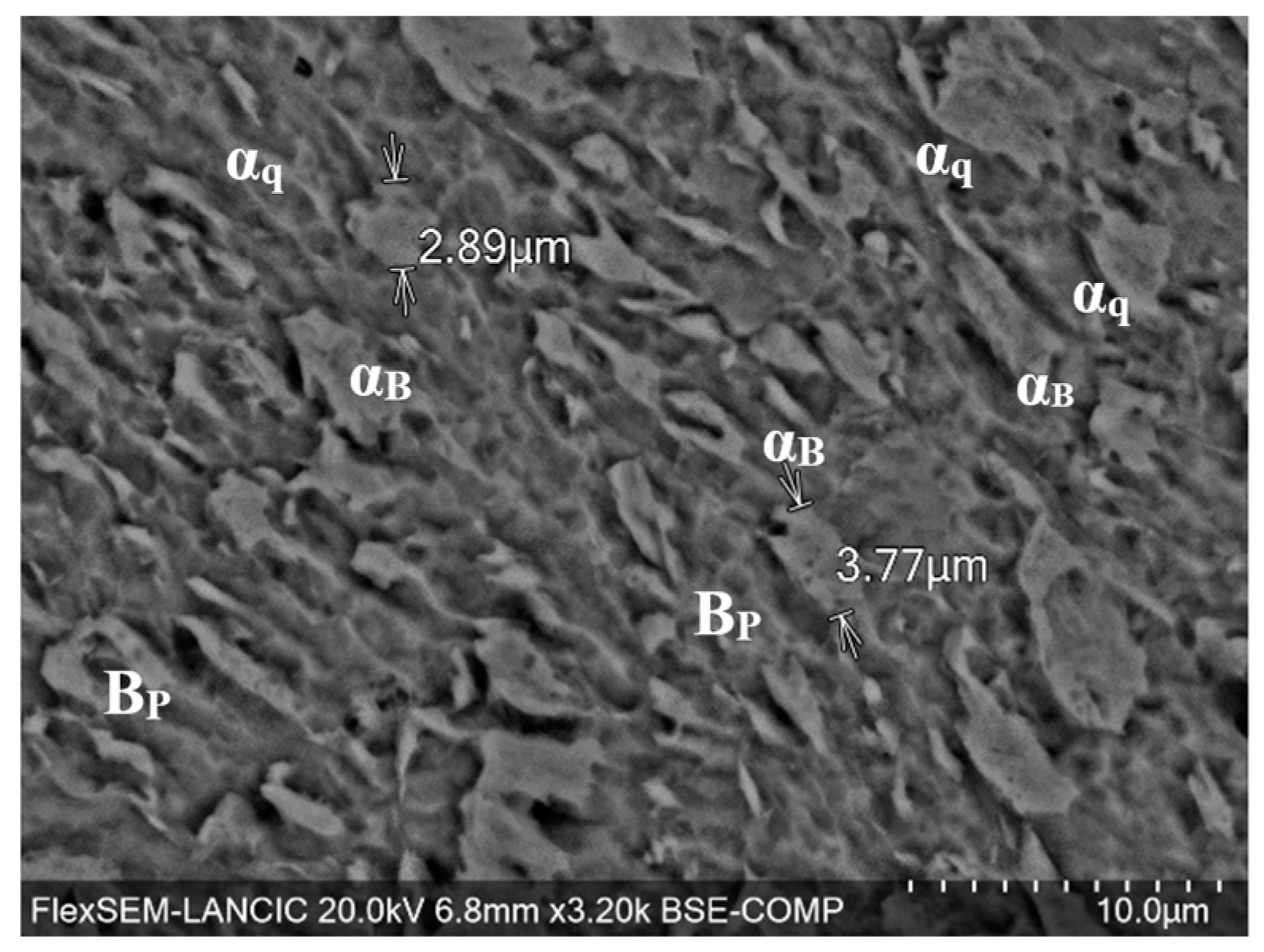
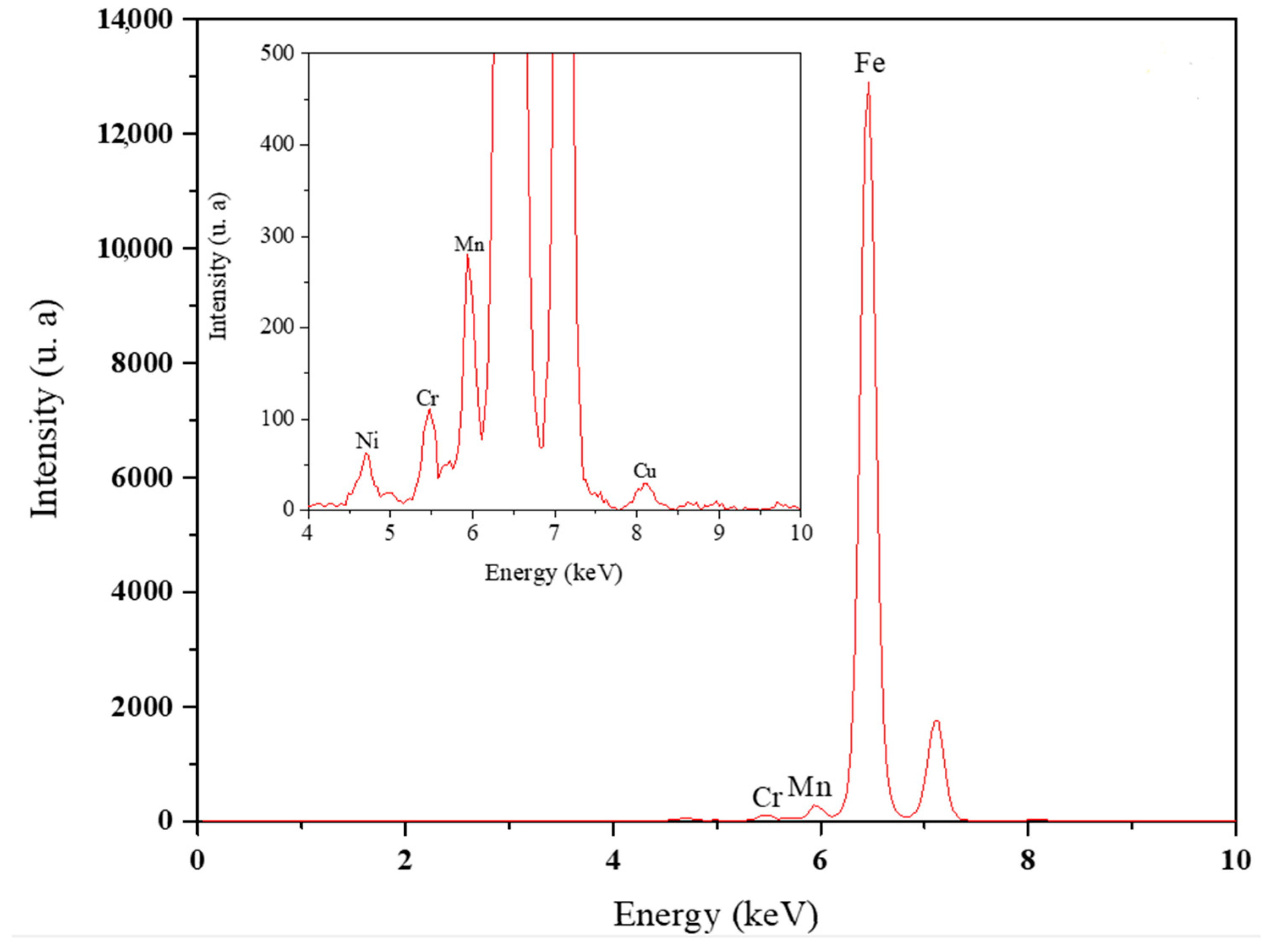
3.2. Elemental and Microstructural Analysis

Figure 1 shows the SEM images of the microstructure for the X100 steel. From Figure 1, a uniform distribution of the grains corresponding to bainitic ferrite (αB) and the presence of some quasipolygonal (αq) and deformed ferrites, which are originated in the rolling process, can be observed. Furthermore, bainite plates (Bp) were also identified in the microstructure. Nafisi et al. [37] also reported a predominant morphology of bainite and bainite plate forming in groups. In addition, Carretero et al. [32] observed polygonal and quasipolygonal ferrite and small fractions of bainitic ferrite in X100 steel. As shown in Figure 2, the EDS mapping of the microstructure showed that the majority of elements, such as Fe, Mn, Ni, Cu, Cr and Si, are uniformly distributed without agglomerations in preferential sites. This fact is beneficial for obtaining optimal results in their mechanical properties [5]. Likewise, the presence of the chemical elements that constitute the X100 steel was confirmed by XRF, as shown in Figure 3, where it was possible to identify low-intensity signals corresponding to microalloying elements such as Si, Ni, Cr, Mn and Cu in the range of 4 to 9 keV, which coincides with the chemical composition of Table 1.

3.3. Electrochemical Evaluation of X100 Steel: Hydrodynamics Parameters and Ecorr
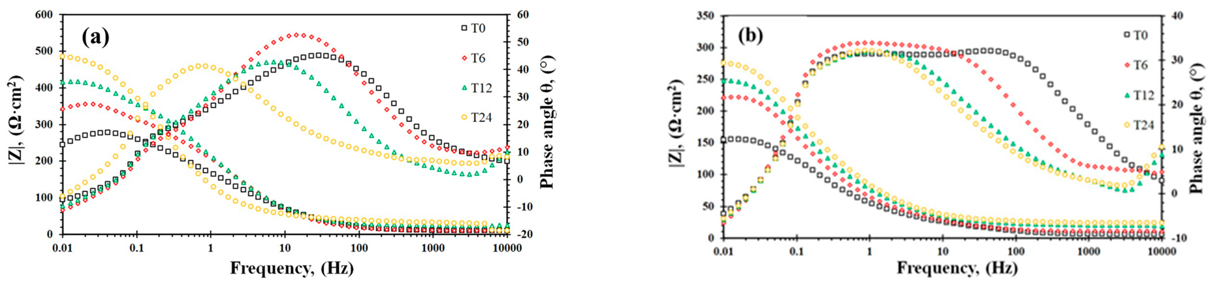
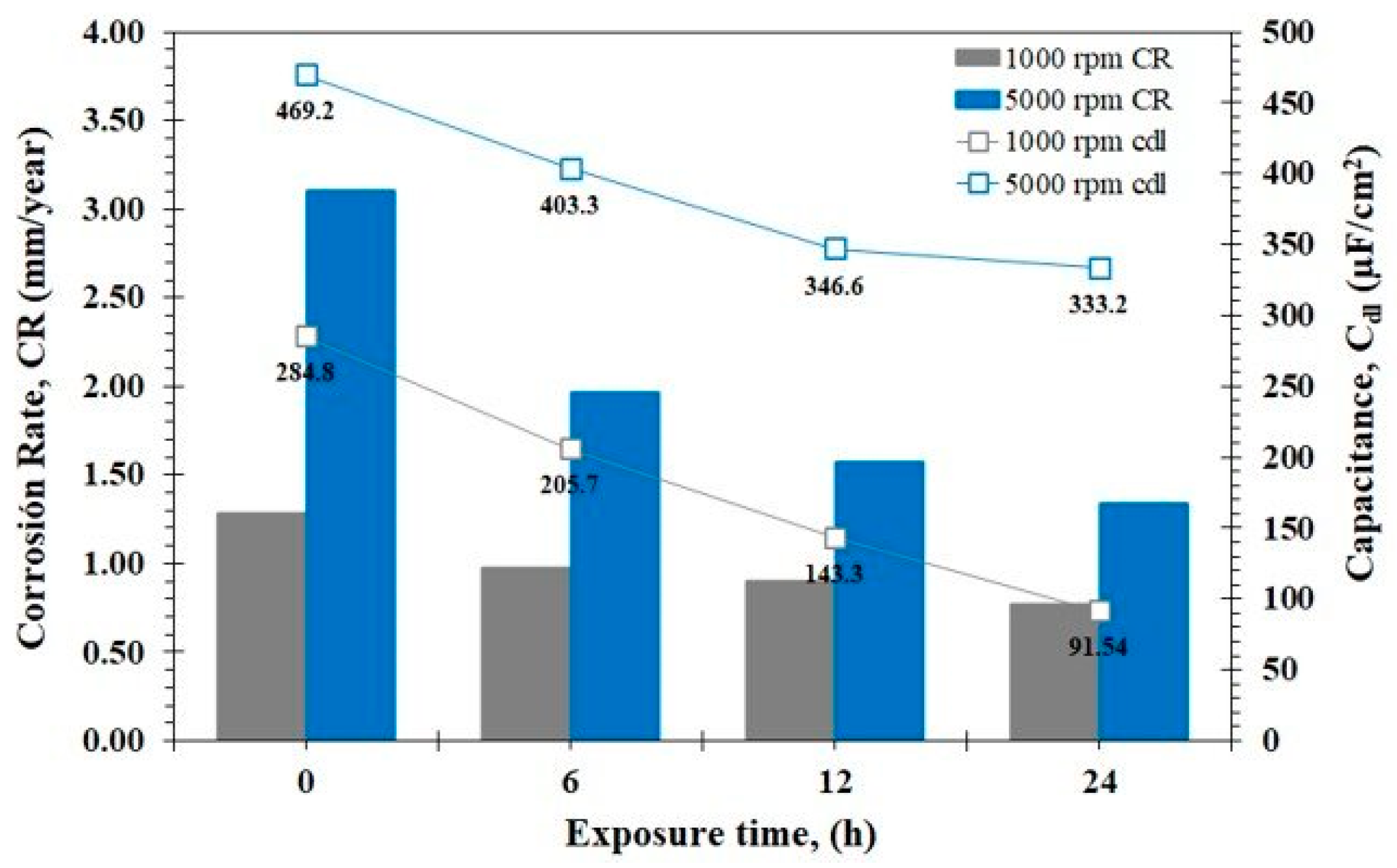
The flow rate of the system has an influence on the electrochemical reactions, and the main parameters in a hydrodynamic system are the Reynolds number (ReRCE) and the shear stress (τRCE). Both parameters help in the functioning of the electrode geometry and physicochemical properties of fluid, as shown in Equations (1) and (2), respectively [23,24,38,39].
R e R C E = U R C E d R C E ρ μ
τ R C E = 0.079 R e R C E 0.3 ρ μ R C E 2
The turbulent boundary layer thickness (δBL) was calculated from the value of ReRCE as follows: [21].
δ B L = 25 · R e 7 8 · D R C E
Equation (4) is used for systems simulating flow conditions, such as rotating cylindrical electrodes (RCEs), using the first Fick’s Law and the Eisenberg Equation [40]:
δ B L = 12.64 d R C E 0.3 D 0.356 ν 0.344 U 0.7
Table 3 shows the hydrodynamic parameters and Ecorr values at several rotation rates. It is observed that, based on Re values, it can be assumed that, in both rotation rates, the fluid presents fully developed turbulence [38,41]. Furthermore, large values of τ also were obtained, which allows for correlating the mechanical force originated by the hydrodynamic conditions and its action on the film of corrosion products generated on the metal surface, being 2.18 and 33.72 N/m2 at 1000 and 5000 rpm, respectively.
On the other hand, a decrease in the δBL is observed as the rotation rate increases. This process facilitates the transport of corrosive species from the bulk solution to the metal surface. Yabuki and Murakami [42] mentioned that the mass transfer coefficient is inversely proportional to the δBL as well as to the thickness of the corrosion products film. From Table 3, it can be noted that Ecorr shifted toward positive values as the rotation rate increased, which can be attributed to the decrease in the Nernst boundary layer as the rotation rate increased [8].

3.4. EIS Analysis

In order to investigate the effect of a turbulent flow on the electrochemical reactions that take place at the metal–solution interface, EIS measurements were conducted during 24 h of immersion time. Figure 4 shows the Nyquist plots for X100 steel immersed in the brine solution at 1000 rpm and 5000 rpm. For both rotation rates (Figure 4a,b), the Nyquist curves presented a well-defined capacitive semicircle characteristic of reaction under a charge transfer control at all exposure times. Moreover, these curves exhibited an inductive loop at low frequencies that was attributed to the adsorption phenomena of intermediate species from anodic and cathodic reactions [43]. At 5000 rpm (Figure 4b), a further increase in the flow rate caused a decrease in the Nyquist semicircles, indicative of an increase in the corrosion rate. The hydrodynamic conditions have two effects: modification of the turbulent boundary layer structure, which suggests the elimination of viscous forces in the internal region, resulting in the decrease in the boundary layer thickness (Table 3) and the elimination or partial removal of the protective film [44,45,46]. When the thickness of the boundary layer decreases, the transport of electroactive species from the bulk solution to the metal surface through convection and diffusion is enhanced, and thus the charge transfer decreases. Therefore, the high turbulence and the τ avoid the formation of homogeneous films and cause the active dissolution of the metal [47,48,49].
Bode plots of the impedance modulus (|Z|) and angle phase (θ) at different rotation rates are shown in Figure 5. For both flow rates (Figure 5a,b), the |Z| value increased with respect to the exposure time. In Bode plots of θ, two time constants were identified at 0, 6 and 12 h of exposure time at 1000 rpm (Figure 5a). It is important to point out that the time constant in the frequency range of high and intermediate frequencies (1000–10 Hz) can be associated with the presence of a film of corrosion products, whereas the time constant in the range of low frequencies (1–0.1 Hz) was attributed to the charger transfer process. For 5000 rpm (Figure 5b), the Bode plot exhibited the two overlapping time constants. It should be pointed out that the θ value shifted toward lower frequencies in the range of 10,000–1 Hz for both the rotation rates, which can be related to the values obtained in the real impedance (ZR) as well as to the charge transfer-dominated processes [50,51].
Based on the qualitative analysis of the EIS spectra for steel subjected to different turbulent flow conditions, a schematic representation of the corrosion mechanism was proposed in Figure 6 along with an equivalent electrical circuit (EEC) model for fitting EIS data and describing the metal–solution interface. The reactions that take place at the interface are the anodic dissolution of Fe and the cathodic reaction of dissolved O2, as shown in Equations (5) and (6), respectively.
F e F e 2 + + 2 e
O 2 + 2 H 2 O + 4 e 4 O H
F e 2 + + 2 O H F e ( O H ) 2
F e 2 + + 2 H 2 O F e O H a d s + H + + e
After the Fe2+ cations and the cathodic reaction products are released, Fe oxyhydroxides can be generated to form a film, or they can solvate and remain adsorbed on the metal surface (Equations (7) and (8)). However, turbulent flow conditions cause several effects, such as chaotic changes in the flow geometry and a considerable increase in the τ, which lead to the rupture of the film of corrosion products. In this context, it is important to point out that, at a high flow rate (5000 rpm), the recovery of the film of the corrosion products will be slower once it is removed [38]. According to Nesic et al. [46], if the shear stress exerted on the metal surface has a magnitude greater than the adhesion strength of the corrosion product film, it will cause the removal of the surface films, leading to an acceleration of corrosion kinetics.
The EEC is composed of a resistor representing the solution resistance (Rs), followed by the a constant phase element CPE indicated as (Qfilm) and a resistor (Rfilm), with both elements being attributed to the presence of a corrosion product film, a resistor associated to the charge transfer resistance. (Rct), a constant phase element (CPE) represented as Qdl that describes the behavior of a non-ideal electrochemical double layer, the parameter n is related to surface properties such roughness, metal dissolution, as well as films on the surface [43,52]. Finally, an inductive element (L) and its resistance (RL) were included in the EEC, which are characteristic of the adsorption phenomenon observed at low frequencies. Several studies have implemented the same EEC model proposed in this research [47,53,54,55].
Table 4 shows the parameters obtained from the fitting with the EEC. In both rotation rates, an increment in Rs is observed from 5 up to 30 Ω cm2 as a function of the exposure time. This increment can be attributed to the saturation of the electrolyte by the presence of oxyhydroxides that form the film of corrosion products, which are eliminated from the surface through the shear stress and incorporated into the solution, therefore decreasing the conductivity and increasing the resistance. In the case of 1000 rpm, both Rfilm and Rct values increased with respect to the exposure time. Meanwhile, when increasing the rotation rate at 5000 rpm, the Rct values were significantly lower than at 1000 rpm. However, the Rfilm exhibited higher values than those obtained at 1000 rpm at exposure times of T0 and T6. This behavior was related to the high mass transfer induced by the hydrodynamic conditions, which enhanced the generation of Fe2+ so that reactions 7 and 8 take place and a film of corrosion products is formed. However, according to the nature of the electrolyte, the films generated are not protective or homogeneous, and, combined with the turbulent flow conditions, they are removed and their precipitation is slow; this is observed in the values obtained at longer exposure periods of T12 and T24, with a decrease to 28 and 30 Ω·cm2, respectively [20].
Based on the CPE parameters (Y0 and n) obtained from the fitting of EIS data, the real capacitance of a double layer (Cdl) was calculated using the Brug equation (Equation (9)) [56].
C d l = Y 0 1 n 1 R s + 1 R c t n 1 n
In addition, the Rct value was used to calculate the corrosion rate (CR) according to the procedure described in ASTM G102 [57]. The CR and Cdl values for X100 steel under turbulent flow conditions are shown in Figure 7. At 1000 rpm, CR values of less than 1.5 mm/year are observed, and these values decreased with respect to the exposure time. It is important to point out that directly proportional behavior in the Cdl values is observed, and this is related to the nature of the films formed as well as to the hydrodynamic conditions, resulting more protective at 1000 rpm as compared to 5000 rpm, where the CR increases at 3 mm/year approximately.
According to Schmitt and Bakalli [58], during conditions of maximum turbulence, an abrupt increase in the CR is experienced since the system is under the domain of mass transfer. Moreover, the intensity of the local flow prevents the formation of a new film due to the shear stress intensity. In accordance with this fact, both CR and Cdl were higher at 5000 rpm than at 1000 rpm; however, both rotation rates show a tendency to decrease with respect to the exposure time. Wang et al. [21] reported a similar tendency in the Cdl values in a sample of X100 steel in sweet brine solution at 1000 rpm where the decrement of the Cdl values were attributed to the FeCO3 absorption.

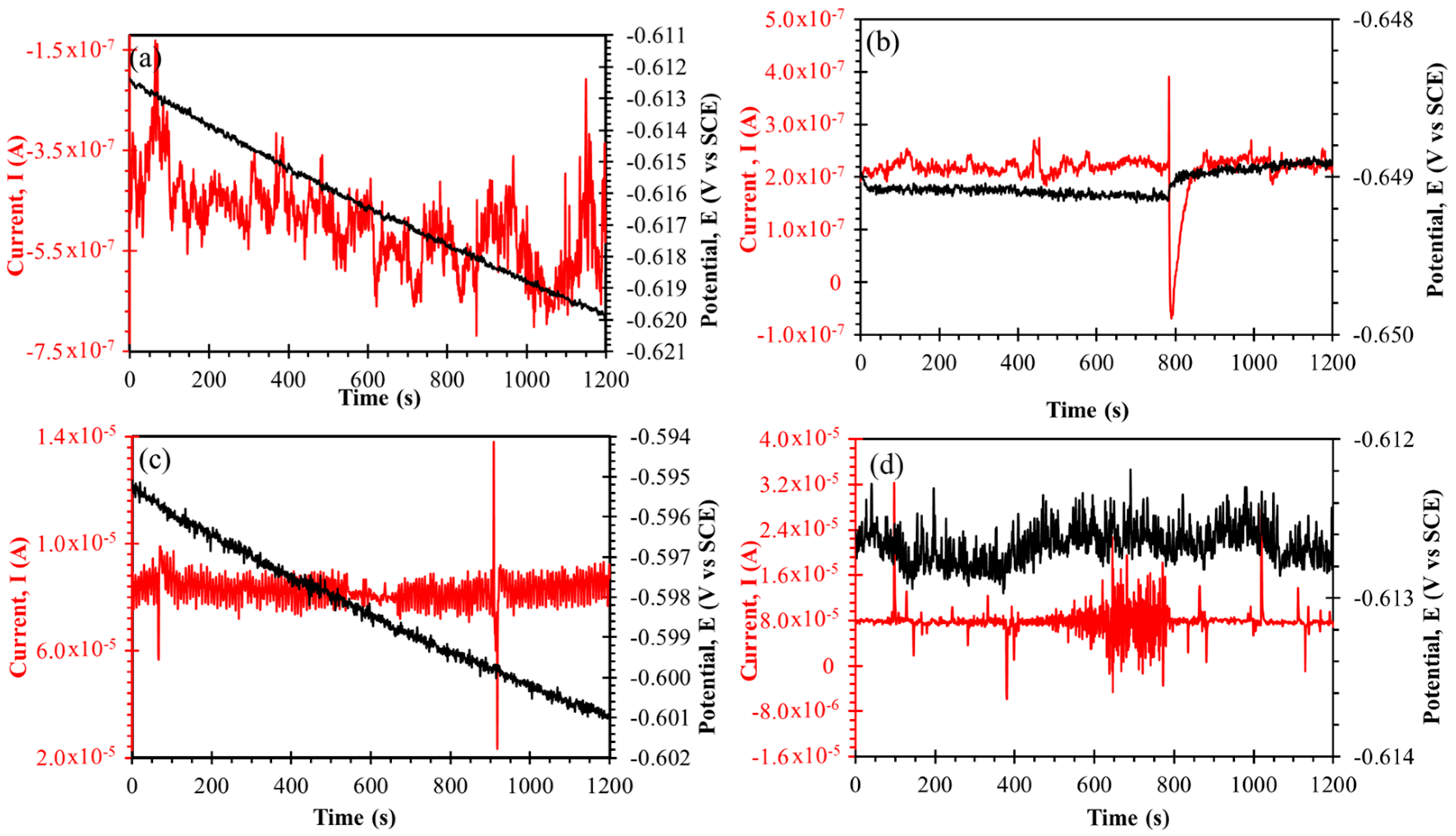
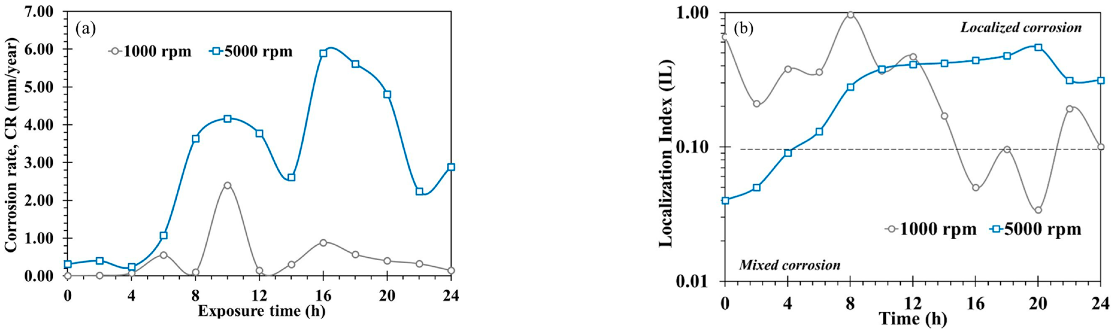
3.5. Electrochemical Noise (EN)

Figure 8 shows the row potential and current time series at different hydrodynamic conditions. At 1000 rpm (Figure 8a,b), both the potential and current signal showed fluctuations of low amplitude (40 μV and 0.2 μA, respectively). The current signal showed overlapped transients at the beginning of the exposure time, and they turned into typical transients (a sharp decrease followed by a slow recovery of the current value) associated with the localized corrosion events at 24 h of exposure [59]. For 5000 rpm (Figure 8c,d), the amplitude of fluctuations was higher than those obtained in 1000 rpm, which reveals the increment of anodic activity as the rotation rate increased. Furthermore, several transients of high amplitude (~30 μA) and short lifetime were identified in the current signal, increasing the number of transients as the exposure time increased. These transients can be associated with the rupture of the corrosion product film caused by the shear stress induced by the rotation rate, which increased the frequency of the localized corrosion attack as time elapsed.
A statistical analysis derived from EN measurements was carried out to calculate the statistical parameters of noise resistance (Rn) and the localization index (LI). Rn is a parameter related to corrosion resistance that is defined as the ratio of the standard deviations of the potential (σE) and current (σI). On the other hand, LI can provide information about the corrosion type. This parameter is the standard deviation of the current noise divided by the root mean square current [60]. Figure 9 shows the behavior of CR and LI values as a function of time at different turbulent flow conditions. The CR values obtained from Rn were gathered using the same procedure described for EIS (Rct) measurements [55]. As shown in Figure 9a, the higher CR values were presented at 5000 rpm with the increasing trend in the CR during the exposure time. Although the flow rate can produce a competition process between the enhancement of the supply of the oxidizing species to the interface and the limitation of these species due to mass transfer processes, the rotation rate contributed largely to accelerating the corrosion process. Furthermore, most of the LI (Figure 9b) values were in the range of 0.1–1, indicating that localized corrosion was the predominant corrosion-type under hydrodynamic conditions [61].

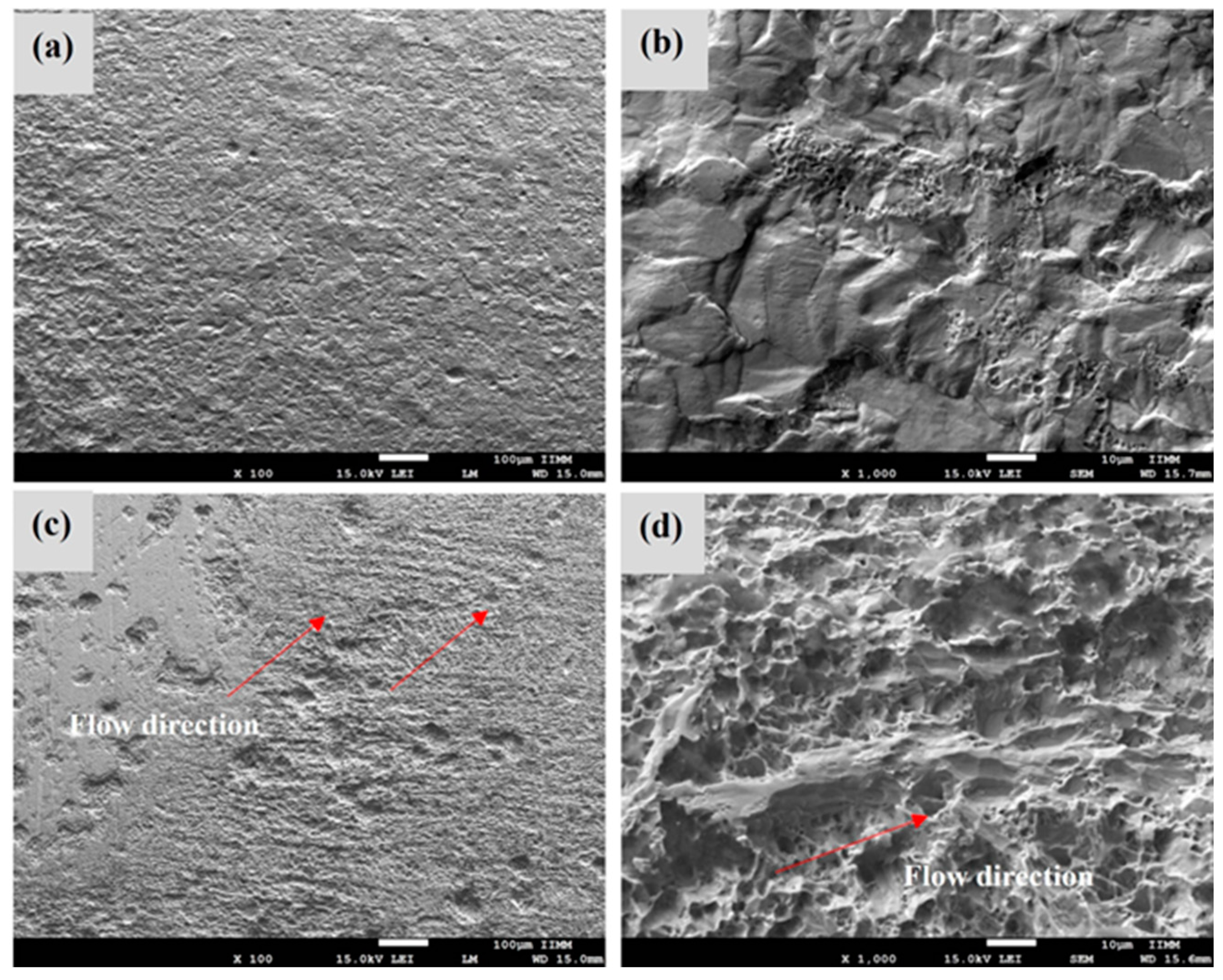
3.6. SEM Analysis of Corrosion Morphology

According to the analysis of the electrochemical measurements, the X100 steel at 5000 rpm experienced the highest CR. This is due to the fully developed flow, which enhances mass transport. The SEM examination of the corroded samples confirmed this fact. In Figure 10, it is possible to observe that, in both dynamic conditions, the corrosive attack was localized; at 1000 rpm, the morphology is characterized by dispersed cavities in specific areas, while, at 5000 rpm, a greater nucleation of holes is observed, as well as greater depths, generating a worn and rough surface.
On the other hand, it can be seen the flow pattern randomly distributed on the metal wall originated by the τ. Li et al. [37] claimed that the shear stress is a determining factor as its impact on the metal surface is not uniform and causes an asymmetric distribution of the holes. Due to this fact, it is observed in Figure 10c,d that the corrosion product layers were removed, and both the surface area of the anodic sites were increased as well as the amount of freshly exposed area, confirming the increment of the CR at 5000 rpm.

4. Conclusions

According to the electrochemical analysis of X100 steel in NACE brine solution under different turbulent flow conditions, the followings conclusions were obtained:
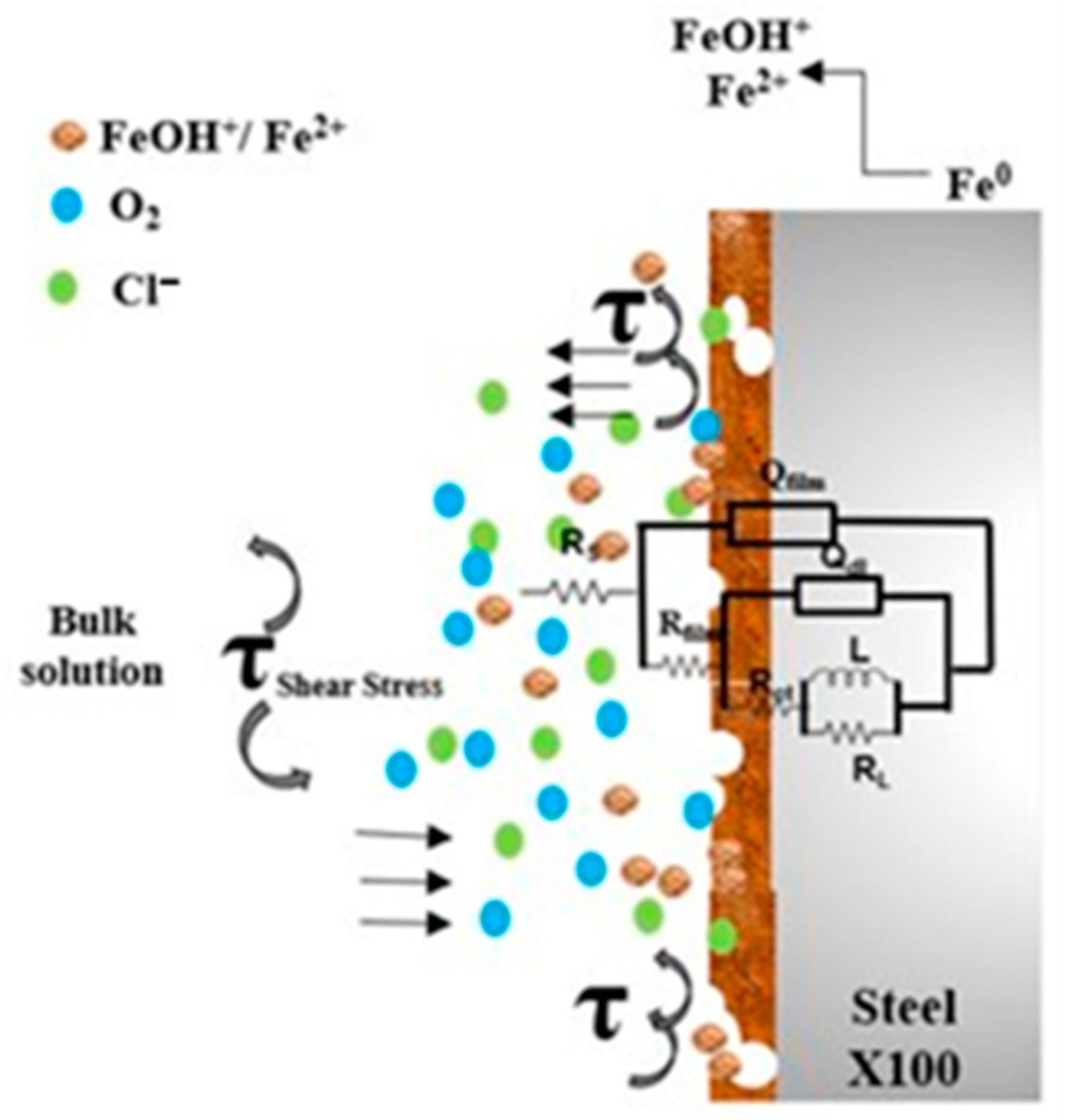
  • The hydrodynamic parameters of the medium had a significant influence on the electrochemical behavior of the steel. The shear stress increased with increasing rotation rate and the thickness of the boundary layer decreased allowing mass transfer from bulk solution to the metal surface through diffusion and convection phenomena.
  • The analysis of EIS revealed that there was an increase in CR of almost double at 5000 rpm with respect to the 1000 rpm system, Cdl showed a behavior directly proportional to CR.
  • Statistical analysis of EN indicated that localized attack was more severe as rotation rate increased from 1000 to 5000 rpm. SEM micrograph confirmed this fact, the attacked metal surface showed a localized corrosion process, with deep pits nucleating, and greater wear was observed at 5000 rpm due to turbulent flow and shear stress.

Author Contributions

Conceptualization, R.G.-M. and C.C.-L.; methodology, R.G.-M. and C.C.-L.; software, F.L.-H. and M.Á.H.-P.; validation, E.M.-S., J.A.R.-C. and C.C.-L.; formal analysis, C.C.-L. and A.C.-H.; investigation, R.G.-M.; resources, R.G.-M. and R.O.-C.; data curation, F.L.-H.; writing—original draft preparation, A.C.-H. and R.O.-C.; writing—review and editing, A.C.-H. and J.A.R.-C.; visualization, M.Á.H.-P. and J.A.R.-C.; supervision, E.M.-S.; project administration, R.O.-C. All authors have read and agreed to the published version of the manuscript.

Funding

This research received no external funding.

Data Availability Statement

The data presented in this work are available on request from the corresponding authors.

Acknowledgments

The authors express their gratitude to National Council for Science and Technology (CONACYT), the Foundry Laboratory from Institute of Metallurgy and Materials Research of the Michoacana University and the Doctorate Program of Materials and Nanoscience of MICRONA Center of the Veracruzana University for the financial and technical support to C. Campechano-Lira for the realization of this research.

Conflicts of Interest

The authors declare no conflicts of interest.

References

  1. Gadala, I.M.; Alfantazi, A. Electrochemical Behavior of API-X100 Pipeline Steel in NS4, near-Neutral, and Mildly Alkaline PH Simulated Soil Solutions. Corros. Sci. 2014, 82, 45–57. [Google Scholar] [CrossRef]
  2. Javidi, M.; Bahalaou Horeh, S. Investigating the Mechanism of Stress Corrosion Cracking in Near-Neutral and High PH Environments for API 5L X52 Steel. Corros. Sci. 2014, 80, 213–220. [Google Scholar] [CrossRef]
  3. Wasim, M.; Djukic, M.B. External Corrosion of Oil and Gas Pipelines: A Review of Failure Mechanisms and Predictive Preventions. J. Nat. Gas. Sci. Eng. 2022, 100, 104467. [Google Scholar] [CrossRef]
  4. Villalobos, J.; Del-Pozo, A.; Campillo, B.; Mayen, J.; Serna, S. Microalloyed Steels through History until 2018: Review of Chemical Composition, Processing and Hydrogen Service. Metals 2018, 8, 351. [Google Scholar] [CrossRef]
  5. Al-Mansour, M.; Alfantazi, A.M.; El-boujdaini, M. Sulfide Stress Cracking Resistance of API-X100 High Strength Low Alloy Steel. Mater. Des. 2009, 30, 4088–4094. [Google Scholar] [CrossRef]
  6. Monschein, S.; Kapp, M.; Zügner, D.; Fasching, J.; Landefeld, A.; Schnitzer, R. Influence of Microalloying Elements and Deformation Parameters on the Recrystallization and Precipitation Behavior of Two Low-Alloyed Steels. Steel Res. Int. 2021, 92, 2100065. [Google Scholar] [CrossRef]
  7. Qian, L.-Y.; Fang, G.; Zeng, P.; Wang, L.-X. Correction of Flow Stress and Determination of Constitutive Constants for Hot Working of API X100 Pipeline Steel. Int. J. Press. Vessel. Pip. 2015, 132–133, 43–51. [Google Scholar] [CrossRef]
  8. Zhao, Y.; Liang, P.; Shi, Y.; Zhang, Y.; Yang, T. The Pitting Susceptibility Investigation of Passive Films Formed on X70, X80, and X100 Pipeline Steels by Electrochemical Noise and Mott-Schottky Measurements. Int. J. Corros. 2015, 2015, 298584. [Google Scholar] [CrossRef]
  9. Zhao, J.; Xiong, D.; Gu, Y.; Zeng, Q.; Tian, B. A Comparative Study on the Corrosion Behaviors of X100 Steel in Simulated Oilfield Brines under the Static and Dynamic Conditions. J. Pet. Sci. Eng. 2019, 173, 1109–1120. [Google Scholar] [CrossRef]
  10. Jin, T.Y.; Cheng, Y.F. In Situ Characterization by Localized Electrochemical Impedance Spectroscopy of the Electrochemical Activity of Microscopic Inclusions in an X100 Steel. Corros. Sci. 2011, 53, 850–853. [Google Scholar] [CrossRef]
  11. Bahgat Radwan, A.; Sliem, M.H.; Okonkwo, P.C.; Shibl, M.F.; Abdullah, A.M. Corrosion Inhibition of API X120 Steel in a Highly Aggressive Medium Using Stearamidopropyl Dimethylamine. J. Mol. Liq. 2017, 236, 220–231. [Google Scholar] [CrossRef]
  12. Zhang, G.; Chen, C.; Lu, M.; Chai, C.; Wu, Y. Evaluation of Inhibition Efficiency of an Imidazoline Derivative in CO2-Containing Aqueous Solution. Mater. Chem. Phys. 2007, 105, 331–340. [Google Scholar] [CrossRef]
  13. Inman, S.B.; Han, J.; Wischhusen, M.A.; Qi, J.; Agnew, S.R.; Ogle, K.; Scully, J.R. Passivation and Localized Corrosion Resistance of Al0.3Cr0.5Fe2MoxNi1.5Ti0.3 Compositionally Complex Alloys: Effect of Mo Content. Corros. Sci. 2024, 227, 111692. [Google Scholar] [CrossRef]
  14. Nešić, S. Key Issues Related to Modelling of Internal Corrosion of Oil and Gas Pipelines—A Review. Corros. Sci. 2007, 49, 4308–4338. [Google Scholar] [CrossRef]
  15. Askari, M.; Aliofkhazraei, M.; Ghaffari, S.; Hajizadeh, A. Film Former Corrosion Inhibitors for Oil and Gas Pipelines—A Technical Review. J. Nat. Gas. Sci. Eng. 2018, 58, 92–114. [Google Scholar] [CrossRef]
  16. El-Gammal, M.; Mazhar, H.; Cotton, J.S.; Shefski, C.; Pietralik, J.; Ching, C.Y. The Hydrodynamic Effects of Single-Phase Flow on Flow Accelerated Corrosion in a 90-Degree Elbow. Nucl. Eng. Des. 2010, 240, 1589–1598. [Google Scholar] [CrossRef]
  17. Kain, V. Flow Accelerated Corrosion: Forms, Mechanisms and Case Studies. Procedia Eng. 2014, 86, 576–588. [Google Scholar] [CrossRef]
  18. Wang, L.; Xing, Y.; Liu, Z.; Zhang, D.; Du, C.; Li, X. Erosion–Corrosion Behavior of 2205 Duplex Stainless Steel in Wet Gas Environments. J. Nat. Gas Sci. Eng. 2016, 35, 928–934. [Google Scholar] [CrossRef]
  19. Ajmal, T.S.; Arya, S.B.; Thippeswamy, L.R.; Quraishi, M.A.; Haque, J. Influence of Green Inhibitor on Flow-Accelerated Corrosion of API X70 Line Pipe Steel in Synthetic Oilfield Water. Corros. Eng. Sci. Technol. 2020, 55, 487–496. [Google Scholar] [CrossRef]
  20. Tan, Z.; Yang, L.; Zhang, D.; Wang, Z.; Cheng, F.; Zhang, M.; Jin, Y. Development Mechanism of Internal Local Corrosion of X80 Pipeline Steel. J. Mater. Sci. Technol. 2020, 49, 186–201. [Google Scholar] [CrossRef]
  21. Wang, S.; Zhao, J.; Gu, Y.; Xiong, D.; Zeng, Q.; Tian, B. Experimental and Numerical Investigation into the Corrosion Performance of X100 Pipeline Steel under a Different Flow Rate in CO2-Saturated Produced Water. J. Solid State Electrochem. 2021, 25, 993–1006. [Google Scholar] [CrossRef]
  22. Zhang, Q.; Li, J.; Liu, J.; Yin, C.; Qi, Y.; Zhou, J. Internal Localized Corrosion of X100 Pipeline Steel under Simulated Flow Conditions. J. Electroanal. Chem. 2023, 945, 117680. [Google Scholar] [CrossRef]
  23. Walsh, F.C.; Kear, G.; Nahlé, A.H.; Wharton, J.A.; Arenas, L.F. The Rotating Cylinder Electrode for Studies of Corrosion Engineering and Protection of Metals—An Illustrated Review. Corros. Sci. 2017, 123, 1–20. [Google Scholar] [CrossRef]
  24. Barmatov, E.; Hughes, T.; Nagl, M. Efficiency of Film-Forming Corrosion Inhibitors in Strong Hydrochloric Acid under Laminar and Turbulent Flow Conditions. Corros. Sci. 2015, 92, 85–94. [Google Scholar] [CrossRef]
  25. Onyeachu, I.B.; Obot, I.B.; Adesina, A.Y. Green Corrosion Inhibitor for Oilfield Application II: The Time–Evolution Effect on the Sweet Corrosion of API X60 Steel in Synthetic Brine and the Inhibition Performance of 2-(2-Pyridyl) Benzimidazole under Turbulent Hydrodynamics. Corros. Sci. 2020, 168, 108589. [Google Scholar] [CrossRef]
  26. Campechano-Lira, C.; Orozco-Cruz, R.; Bedolla-Jacuinde, A.; Contreras-Cuevas, A.; Galvan-Martinez, R. Electrochemical Analysis of an API X100 Steel Immersed in NACE Brine Solution with Addition of Corrosion Inhibitor. ECS Trans. 2019, 94, 81–89. [Google Scholar] [CrossRef]
  27. ASTM E-23-23a; Test Methods for Notched Bar Impact Testing of Metallic Materials. ASTM: West Conshohocken, PA, USA, 2023.
  28. ASTM E8; Test Methods for Tension Testing of Metallic Materials. ASTM: West Conshohocken, PA, USA, 2022.
  29. ASTM E407-07; Practice for Microetching Metals and Alloys. ASTM: West Conshohocken, PA, USA, 2015.
  30. ASTM G1-03; Practice for Preparing, Cleaning, and Evaluating Corrosion Test Specimens. ASTM: West Conshohocken, PA, USA, 2017.
  31. NACE 1D182; Wheel Test Method Used for Evaluation of Film-Persistent Corrosion Inhibitors for Oilfield Applications. NACE International: Houston, TX, USA, 2017.
  32. Carretero Olalla, V.; Bliznuk, V.; Sanchez, N.; Thibaux, P.; Kestens, L.A.I.; Petrov, R.H. Analysis of the Strengthening Mechanisms in Pipeline Steels as a Function of the Hot Rolling Parameters. Mater. Sci. Eng. A 2014, 604, 46–56. [Google Scholar] [CrossRef]
  33. Nking’wa, A.A.; Gao, K. Study on Stress Corrosion Cracking of X100 Pipeline Steel in NS4 Solution. J. Fail. Anal. Prev. 2024, 24, 1934–1944. [Google Scholar] [CrossRef]
  34. Wang, Z.X.; Zhang, R.F.; Chao, Y.J.; Lam, P.S. Elastic-Plastic Constraint Analysis of Semi-Elliptic Surface Cracks in X100 Pipeline Steel. In Proceedings of the ASME 2011 Pressure Vessels and Piping Conference. Volume 6: Materials and Fabrication, Parts A and B, Baltimore, MD, USA, 17–21 July 2011; pp. 1325–1334. [Google Scholar]
  35. Xu, L.Y.; Cheng, Y.F. Corrosion of X100 Pipeline Steel under Plastic Strain in a Neutral PH Bicarbonate Solution. Corros. Sci. 2012, 64, 145–152. [Google Scholar] [CrossRef]
  36. Yang, X.-L.; Xu, Y.-B.; Tan, X.-D.; Wu, D. Relationships among Crystallographic Texture, Fracture Behavior and Charpy Impact Toughness in API X100 Pipeline Steel. Mater. Sci. Eng. A 2015, 641, 96–106. [Google Scholar] [CrossRef]
  37. Nafisi, S.; Arafin, M.A.; Collins, L.; Szpunar, J. Texture and Mechanical Properties of API X100 Steel Manufactured under Various Thermomechanical Cycles. Mater. Sci. Eng. A 2012, 531, 2–11. [Google Scholar] [CrossRef]
  38. Bianchi, G.L.; Acosta, V.; Seijas, C. A Combination of Laboratory Testing, RCE, and Corrosion Loop for Inhibitor Selection. Appl. Sci. 2023, 13, 4586. [Google Scholar] [CrossRef]
  39. Li, Y.; Chen, M.; Li, J.; Song, L.; Zhang, X.; Liu, Z. Flow-Accelerated Corrosion Behavior of 13Cr Stainless Steel in a Wet Gas Environment Containing CO2. Int. J. Miner. Metall. Mater. 2018, 25, 779–787. [Google Scholar] [CrossRef]
  40. Wang, X.; Ouyang, J.; Wang, Z.M. Exploring the Dynamic Mechanism of Water Wetting Induced Corrosion on Differently Pre-Wetted Surfaces in Oil–Water Flows. J. Colloid Interface Sci. 2024, 664, 284–298. [Google Scholar] [CrossRef]
  41. Gabe, D.R.; Walsh, F.C. The Rotating Cylinder Electrode: A Review of Development. J. Appl. Electrochem. 1983, 13, 3–21. [Google Scholar] [CrossRef]
  42. Yabuki, A.; Murakami, M. Breakaway Properties of Film Formed on Copper and Copper Alloys in Erosion–Corrosion by Mass Transfer Equation. Mater. Corros. 2008, 59, 25–31. [Google Scholar] [CrossRef]
  43. Córdoba-Torres, P.; Keddam, M.; Nogueira, R.P. On the Intrinsic Electrochemical Nature of the Inductance in EIS. Electrochim. Acta 2008, 54, 518–523. [Google Scholar] [CrossRef]
  44. Du, C.; Zhao, T.; Liu, Z.; Li, X.; Zhang, D. Corrosion Behavior and Characteristics of the Product Film of API X100 Steel in Acidic Simulated Soil Solution. Int. J. Miner. Metall. Mater. 2016, 23, 176–183. [Google Scholar] [CrossRef]
  45. Schrader, L.U.; Amin, S.; Brandt, L. Transition to Turbulence in the Boundary Layer over a Smooth and Rough Swept Plate Exposed to Free-Stream Turbulence. J. Fluid. Mech. 2010, 646, 297–325. [Google Scholar] [CrossRef]
  46. Nesic, S. Effects of Multiphase Flow on Internal CO2 Corrosion of Mild Steel Pipelines. Energy Fuels 2012, 26, 4098–4111. [Google Scholar] [CrossRef]
  47. Heitz, E. Chemo-Mechanical Effects of Flow on Corrosion. Corrosion 1991, 47, 135–145. [Google Scholar] [CrossRef]
  48. Farelas, F.; Galicia, M.; Brown, B.; Nesic, S.; Castaneda, H. Evolution of Dissolution Processes at the Interface of Carbon Steel Corroding in a CO2 Environment Studied by EIS. Corros. Sci. 2010, 52, 509–517. [Google Scholar] [CrossRef]
  49. Xu, Y.; Tan, M.Y. Probing the Initiation and Propagation Processes of Flow Accelerated Corrosion and Erosion Corrosion under Simulated Turbulent Flow Conditions. Corros. Sci. 2019, 151, 163–174. [Google Scholar] [CrossRef]
  50. Bommersbach, P.; Alemany-Dumont, C.; Millet, J.-P.; Normand, B. Hydrodynamic Effect on the Behaviour of a Corrosion Inhibitor Film: Characterization by Electrochemical Impedance Spectroscopy. Electrochim. Acta 2006, 51, 4011–4018. [Google Scholar] [CrossRef]
  51. Orazem, M.E.; Pébère, N.; Tribollet, B. Enhanced Graphical Representation of Electrochemical Impedance Data. J. Electrochem. Soc. 2006, 153, B129. [Google Scholar] [CrossRef]
  52. Markhali, B.P.; Naderi, R.; Mahdavian, M.; Sayebani, M.; Arman, S.Y. Electrochemical Impedance Spectroscopy and Electrochemical Noise Measurements as Tools to Evaluate Corrosion Inhibition of Azole Compounds on Stainless Steel in Acidic Media. Corros. Sci. 2013, 75, 269–279. [Google Scholar] [CrossRef]
  53. Córdoba-Torres, P.; Keddam, M.; Nogueira, R.P. On the Intrinsic Electrochemical Nature of the Inductance in EIS—A Monte Carlo Simulation of the Two-Consecutive Steps Mechanism: The Rough 3D Case and the Surface Relaxation Effect. Electrochim. Acta 2009, 54, 6779–6787. [Google Scholar] [CrossRef]
  54. Umoren, S.A.; Madhankumar, A. Effect of Addition of CeO2 Nanoparticles to Pectin as Inhibitor of X60 Steel Corrosion in HCl Medium. J. Mol. Liq. 2016, 224, 72–82. [Google Scholar] [CrossRef]
  55. Ortega-Toledo, D.M.; Gonzalez-Rodriguez, J.G.; Casales, M.; Caceres, A.; Martinez, L. Hydrodynamic Effects on the CO2 Corrosion Inhibition of X-120 Pipeline Steel by Carboxyethyl-Imidazoline. Int. J. Electrochem. Sci. 2011, 6, 778–792. [Google Scholar] [CrossRef]
  56. Brug, G.J.; van den Eeden, A.L.G.; Sluyters-Rehbach, M.; Sluyters, J.H. The Analysis of Electrode Impedances Complicated by the Presence of a Constant Phase Element. J. Electroanal. Chem. Interfacial Electrochem. 1984, 176, 275–295. [Google Scholar] [CrossRef]
  57. ASTM G102; Practice for Calculation of Corrosion Rates and Related Information from Electrochemical Measurements. ASTM: West Conshohocken, PA, USA, 2015.
  58. Schmitt, H.G.; Bakalli, M. Flow Assisted Corrosion. In Shreir’s Corrosion; Elsevier: Amsterdam, The Netherlands, 2010; pp. 954–987. [Google Scholar]
  59. Cheng, Y.F.; Luo, J.L.; Wilmott, M. Spectral Analysis of Electrochemical Noise with Different Transient Shapes. Electrochim. Acta 2000, 45, 1763–1771. [Google Scholar] [CrossRef]
  60. Montoya-Rangel, M.; Garza-Montes de Oca, N.; Gaona-Tiburcio, C.; Colás, R.; Cabral-Miramontes, J.; Nieves-Mendoza, D.; Maldonado-Bandala, E.; Chacón-Nava, J.; Almeraya-Calderón, F. Electrochemical Noise Measurements of Advanced High-Strength Steels in Different Solutions. Metals 2020, 10, 1232. [Google Scholar] [CrossRef]
  61. Mansfeld, F.; Sun, Z. Technical Note: Localization Index Obtained from Electrochemical Noise Analysis. Corrosion 1999, 55, 915–918. [Google Scholar] [CrossRef]
Figure 1. Microstructure of X100 steel (αq; quasipolygonal ferrite, αB: bainitic ferrite, BP: bainite plate). White arrows indicate grain size.
Surfaces 08 00010 g001
Figure 2. Elemental mapping of constituents in X100 steel.
Surfaces 08 00010 g002
Figure 3. Elemental chemical identification in X100 steel; spectra obtained by XRF.
Surfaces 08 00010 g003
Figure 4. Nyquist plots of X100 steel immersed in NACE brine solution at different rotational velocities. (a) 1000 rpm and (b) 5000 rpm.
Surfaces 08 00010 g004
Figure 5. Bode plots of X100 steel immersed in NACE brine solution at different rotational velocities. (a) 1000 rpm and (b) 5000 rpm.
Surfaces 08 00010 g005
Figure 6. Physical representation of the corrosion mechanism of X100 steel under turbulent flow conditions and the EEC proposed for the fitting of the EIS spectra.
Surfaces 08 00010 g006
Figure 7. CR and Cdl values of X100 steel immersed in NACE brine solution under turbulent flow conditions.
Surfaces 08 00010 g007
Figure 8. The potential and current time series for X100 steel immersed in NACE brine solution under turbulent flow conditions at: (a) 1000 rpm at 0 h, (b) 1000 rpm at 24 h, (c) 5000 rpm at 0 h, (d) 5000 rpm at 24 h.
Surfaces 08 00010 g008
Figure 9. (a) The CR and (b) IL values of X100 steel immersed in NACE brine solution under turbulent flow conditions.
Surfaces 08 00010 g009
Figure 10. SEM images of the corroded samples of X100 steel after 24 h immersion in NACE brine solution at different rotation rates: (a,b) 1000 rpm and (c,d) 5000 rpm.
Surfaces 08 00010 g010
Table 1. Chemical composition of X100 steel.
ElementFeCMnSiCuNiCrMoNbVTi
wt.% 96.390.051.750.360.510.290.360.190.030.030.04
Table 2. Mechanical properties of X100 steel.
Stress-StrengthCharpy ImpactVickers Hardness
YS-0.02 %UTSImpact energyHV
(MPa)(MPa)(J)(kgf·mm2)
641891.5120220
Table 3. Hydrodynamic parameters and Ecorr value of X100 steel under turbulent flow conditions immersed in NACE brine solution.
Rotation Velocity (rpm)Reynolds Number ReRCEShear Stress τRCE (N/m2)Thickness Boundary Layer δBL (m)Corrosion Potential Ecorr (V vs. SCE)
0---−0.680
10008157.82.182.18 × 10−10−0.600
500040,789.133.727.074 × 10−11−0.550
Table 4. Electrochemical parameters for X100 steel in NACE brine solution obtained from EEC fitting.
Rotation
Velocity
Exposure Timeχ2RsQfilmRfilmQdlRctLRL
(rpm)(h) (Ω·cm2)Yon(Ω·cm2)Yon(Ω·cm2)(H)(Ω·cm2)
100002.11 × 10−39.208.32 × 10−40.7328.103.35 × 10−40.94235117491.70
64.15 × 10−39.707.83 × 10−40.7130.503.57 × 10−40.803091527309.00
122.89 × 10−323.107.42 × 10−40.7235.002.33 × 10−40.843351889314.10
246.25 × 10−329.706.88 × 10−40.70152.001.34 × 10−40.893921941340.0
500001.85 × 10−35.102.24 × 10−30.8049.565.28 × 10−30.859788096.00
62.50 × 10−310.371.84 × 10−30.7149.364.55 × 10−30.7515395476.00
122.52 × 10−320.111.39 × 10−30.8028.003.76 × 10−30.80192786132.20
242.46 × 10−423.841.24 × 10−30.8030.003.54 × 10−30.80225765178.90
Disclaimer/Publisher’s Note: The statements, opinions and data contained in all publications are solely those of the individual author(s) and contributor(s) and not of MDPI and/or the editor(s). MDPI and/or the editor(s) disclaim responsibility for any injury to people or property resulting from any ideas, methods, instructions or products referred to in the content.

