Abstract
Owing to the light weight and high energy, the “All-aluminum engine” can reduce fuel consumption and pollutant emissions, showing a great significance in saving resources and protecting the environment, and becoming a research hotspot. However, the aluminum alloy cylinder liners have difficulty withstanding extremely harsh working conditions, such as strong friction and wear, making the engine extremely easy to damage. In this work, Al-25Si wear-resistant coating was deposited by inner hole supersonic plasma spraying technique to improve the wear resistance of the aluminum alloy cylinder liner. The microstructure, phase composition, mechanical properties and tribological properties were tested by SEM, XRD, tribological machine, etc. The results indicated that the coating exhibited an excellent bonding strength of 44.1 MPa, and the average hardness and average friction coefficient of the coating are 267.09 ± 14.85 HV0.2, and 0.20, respectively. The total wear amount, the wear scar width and the wear scar depth of the coating are 2.77 × 10⁻³ mm3, 654.3 μm and 8.95 μm, respectively, which showed that the coating can significantly improve the tribological properties of the “All-aluminum engine”. The wear mechanism of the coating was mainly interpreted by furrow cutting, extrusion and spalling in two-body abrasive wear, three-body abrasive wear and a small amount of oxidative wear.
1. Introduction
As a conversion device to transfer chemical energy to mechanical energy, the engine is the power source of equipment and facilities, such as tanks, ships, and construction machinery. The performance of the energy is of great significance to improve the equipment property. In recent years, “all-aluminum engines” have received extensive attention, which is expected to achieve a lightweight design of the engine and reduce fuel consumption and pollutant emissions [1,2]. Specifically, aluminum alloy materials (mainly aluminum–silicon alloys) with low density, high specific strength, corrosion resistance, and excellent thermal conductivity was proposed and designed to replace the conventional cast iron materials [3,4]. Figure 1 shows the cylinder block and cylinder head of a heavy-duty engine made of aluminum alloy. The engine block is a typical reciprocating inner hole part. When it is operating, the combustion chamber is in extreme conditions of high temperature, high load and lean oil, making the inner wall surface prone to strain, wear and corrosion [5]. Therefore, the cast iron cylinder liners with a high strength, high temperature resistance and fatigue resistance are commonly embedded inside the cylinder block. However, the usage of cast iron cylinder liners not only increases the overall weight and manufacturing cost of the engine, but also reduces the performance and safety due to the low thermal conductivity and the mismatched thermal expansion coefficient.
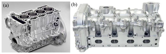
Figure 1.
Aluminum alloy engine: (a) engine block; (b) engine cylinder head.
In order to manufacture an all-aluminum engine, the hypereutectic Al-Si alloy materials (high-silicon aluminum alloy) with high specific strength, excellent thermal conductivity, and low thermal expansion coefficient was applied to replace the cast iron to manufacture the cylinder liner [6,7,8,9,10,11,12,13]. However, this material increases the manufacturing process and cost. Besides, surface strengthening techniques were also employed to strengthen the inner wall of the aluminum alloy cylinder, such as inner hole thermal spraying [14,15,16,17,18,19], electroplating [20], and coating [21], having the advantages of simple operation, high efficiency and low cost.
Compared with conventionally cast high-silicon aluminum alloys, the rapid solidification techniques, such as Melt Quenching (MQ) [22], Rapid Solidification-Powder Metallurgy (RS-PM) [23], Spray Forming (SF) [24], and Selective Laser Melting, SLM (SLM) [25], could generate fine-grained spherical silicon particles, greatly enhancing the mechanical properties of the alloy. Among them, the supersonic plasma spraying (SAPS) could instantly melt the Al-Si particles with a temperature of 10,000 °C. Subsequently, it only takes 0.2 μs for the particles from the melting to the deposition and solidification on the substrate with a cooling rate as high as 108 K/s. This process with high-temperature heating and rapid cooling shows similar characteristics as the rapid solidification technique.
In addition, in the deposition process of SAPS, the internal stress generated by particle accumulation and dislocations during the fragmentation and splashing between particles would be beneficial to the enhancement of the coating strength. Meanwhile, the inert gas protection could also prevent the oxidation of aluminum alloys [26]. Therefore, the inner hole SAPS is expected to prepare the high silicon aluminum coating on the inner surface of the aluminum alloy cylinder with a certain strength and wear resistance [27,28,29].
In this work, the inner hole SAPS was employed to prepared high silicon aluminum coating on the aluminum alloy cylinder block. The mechanical properties and tribological properties of plasma sprayed Al-25Si wear-resistant coatings were tested, and the mechanism of the tribological properties was discussed. This investigation would providing a technical support for the surface enhancement of inner hole lightweight materials.
2. Experimental Investigation
2.1. Coating Spray Material and Process
The YL113 alloy (YZAl-11Si-3Cu, GB/T15115-2009) was used as the substrate for the all-aluminum engine block, with its specific components listed in Table 1, and the matrix material was cut into two samples of 40 × 10 × 3 mm and Φ25 × 10 mm, and then the surface was pretreated. Generally speaking, in order to improve the bonding strength between the coating and the substrate, mechanical roughening is preferred for the pretreatment of the inner wall of the aluminum alloy cylinder, but considering the limitation of the size of the inner hole of the cylinder and other shortcomings of the mechanical roughening method; it has low chemical cost and high efficiency. It can activate the surface of any position on the inner wall of the cylinder hole. For long holes, it is only necessary to replace the inner hole sandblasting gun without special inner hole sandblasting equipment. Therefore, in this study, alumina particles with a particle size of 18 μm were used for surface sandblasting pretreatment to remove oxide films and oil stains, activate the surface of the substrate, and increase the surface roughness (Figure 2).

Table 1.
The composition of the substrate used for the spraying.
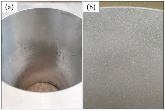
Figure 2.
Sandblasting treatment of aluminum alloy cylinder: (a) before treatment; (b) after treatment.
The Al-25Si-4Cu-0.9Mg powder for spraying was provided by Beijing Sunspray New Materials Co., Ltd. and prepared through gas atomization method with the ratios of 32.0 wt.% of pure Al ingot, 8 wt.% of Al-50Cu, 50 wt.% of Al-50Si and 10 wt.% of Al-10Mg alloy. The melting was conducted under 1300 °C and stirring rate of 1000 rpm. The atomizing was operated with a gas pressure of 0.9 MPa, and a atomizer diameter of 3.6 mm.
The inner hole Al-25Si wear-resistant coating was prepared by a high-energy-speed inner hole flexible rotary plasma spraying equipment (DragonPlamsa RM1, National Key Laboratory of Remanufacturing), and the coating thickness was 350–400 μm. The spraying parameters are presented in Table 2. During the spraying, the inner hole spray gun was placed parallel to the axis of the cylinder liner and took a circular motion along the inner wall of the cylinder liner with an angular velocity of 6π rad/s. Meanwhile, it also took an uniform reciprocating motion along the axis of the cylinder liner with a speed of 18 mm/s. After continuous work for 2~3 cycles, the spray gun was cooled down for 30 s to prevent overheating. The sprayed powder entered into the plasma jet through an inner injection port of Φ1.5 mm, and formed an angle of 80° with the axis of the plasma jet.
Table 2.
Supersonic plasma spraying parameters for the inner hole.
2.2. Powder and Coating Microstructure/Composition Characterization Methods
The chemical composition of the powder and coating was characterized by inductively coupled plasma optical emission spectrometry (ICP-OES, ICPOES730, Agilent, Santa Clara, CA, USA). The crystal structure of the coating and powder was determined by X-ray diffractometer (XRD, D8 ADVANCE, Bruker, Karlsruhe, Germany) with Cu target, Kα ray, scanning speed of 4°/min, diffraction angle of 20–90°, and step size of 0.02°. The surface and cross-section morphologies, elemental distribution of wear scars and debris were observed by using laser confocal three-dimensional topography (3D-OM, LEXT OLS 4000, Olympus, Tokyo Prefecture, Japan), high-resolution field emission scanning electron microscope (SEM, Nova NanoSEM50, FEI, Hillsboro, OR, USA), and energy dispersive spectrometer (EDS, Oxford, UK).
2.3. Microhardness, Bond Strength and Wear Resistance Test of the Coating
The Vickers hardness of the coating was investigated by using an automatic turret microhardness tester (HV-1000A, Shandong, China), with a load of 1.98 N, a dwell time of 10 s, and an interval of 100 μm. The bonding strength of the coating was evaluated according to GB/T 8642-2002 using an universal testing machine (WDW-100, Shanghai, China). The fretting friction and wear testing machine (SRV-4, Optimol, Munich, Germany) was applied to test the friction and wear properties of the coating. The grinding ball is GCr15 (ASTM A295: 1998, 63.5 HRC) with a diameter of 10 mm. The wear was conducted under 120 °C, 20 N load, 0.8 mm reciprocating stroke, and 10 Hz frequency. The friction force (F) and normal load (P) are automatically recorded in the program of the wear tester, and the coefficient of friction (COF) is calculated by F/P. After the friction and wear experiment, the samples were ultrasonically cleaned with acetone for 20 min, and then the wear morphology, size and volume of the samples were measured by 3D-OM. The wear rate was determined based on the wear amount per unit sliding distance. The wear scar width and wear volume were used to evaluate the wear resistance of the coating.
3. Results and Discussion
3.1. Microstructure of the Powder and Al-25Si Coating
Figure 3 shows microscopic morphologies of the Al-25Si-4Cu-0.9Mg powder and inner pore coating. Figure 3a,c present the cross-sectional light microscope images of the powder and coating, in which the blue and the white represent silicon phase and aluminum phase, respectively. Figure 3b,d display the cross-sectional SEM images of the powders and coatings after etching for 45 s using Keller’s reagent (0.5%HF + 1.5%HCl + 2.5%HNO3 + 99.5%H2O). The sieved raw material powder shows spherical morphology with a particle size of 20~50 μm, and thus suitable for plasma spraying.
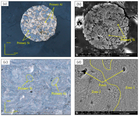
Figure 3.
Micromorphology of the powder and coating: (a) OM image of the powder; (b) SEM image of the powder after the corrosion; (c) OM image of the coating; (d) SEM image of the coating after corrosion.
In addition, the silicon phase in the Al-25Si-4Cu-0.9Mg powder exhibited a large size of 3 μm with a polygonal shape. However, its structure changed greatly after the as-sprayed coating. A layered lap structure was generated after melting. Three typical microstructures were observed in the section of the coating after the corrosion.
Firstly, the featureless Zone 1 displayed litter corrosion, suggesting that the solidification process in this area was non-equilibrium solidification of solid phase without diffusion. This was mainly because the ultra-high cooling rate of SAPS made the silicon phase in this area extremely refined. The microstructure of this region was similar to the hub side of the high-silicon aluminum alloy prepared by the spin quenching method [30,31], due to the similar cooling rates around 108 K/s. However, the feature-free area of the high-alumina-silicon alloy prepared by the spin quenching method was only distributed on the hub side, while that in the high-silicon-alumina coating prepared by SAPS was evenly distributed throughout the coating, which was conductive to the improvement of the mechanical properties of the coating.
Secondly, it can be clearly observed from Figure 3d that the fine-grained region (Zone 2) was mainly composed of spherical Si particles, the size of which was between sub-micron to nano-scale. The formation was mainly attributed to the following two aspects. Firstly, the droplets on the periphery of the plasma jet have a lower temperature and velocity, which made it difficult for the heat of the jet to transfer to the center of the powder and thereby result in the partial melt of some droplets with a larger particle size. The partially melted bulk silicon phases might disintegrate and fixed in the coating by the subsequent spreading of the droplets [26]. Secondly, when the latter droplet was deposited on the previously spread droplet during the spraying process, the local remelting might occur on the contact surface, thereby increasing the grain size of the nano-silicon particles to a certain extent, which made part of the featureless area transform to the fine-grained region. This phenomenon is obvious in the research work of N. Kang [32]. They found that on the laser track, the laser core would melt twice after repeated laser scanning, and its structure was significantly larger than that of the laser space melted only once. The SAPS process can significantly inhibit the growth of silicon phase compared to the instantaneous large heat input in THE SLM process.
Thirdly, the coating deposition mechanism is the process of spreading, cooling, and stacking after high-temperature and high-speed molten particles hit the substrate. Therefore, due to the differences in the melting degree, flight speed, cooling speed of the powder, the thermal spray coating inevitably had inherent defects, such as pores and cracks. Smaller pores could store lubricating oil, thereby reducing the occurrence of dry friction and improving its wear resistance.
Figure 4 shows the elemental contents of Al, Si, Cu, and Mg in the powder and coating measured by ICP technique. Since the average surface temperature of the droplets is above 2500 °C, much higher than the boiling points of Mg (~1107 °C) and Al (~2400 °C), the evaporation of these elements occurred, leading to the almost disappearance of Mg element after spraying. Differently, the Si displayed an increase of about 4 wt.%.
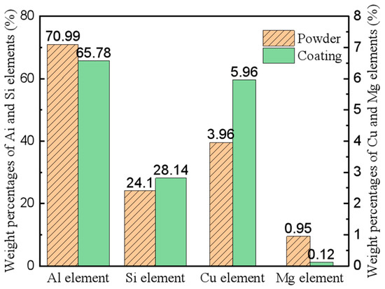
Figure 4.
Composition difference between the powder and coating.
Figure 5 shows the XRD patterns of the powder and the coating. As can be seen from Figure 5a, there are obvious diffraction peaks of θ-Al2Cu in the powder, but none in the coating. This was because the rapid solidification of the SAPS process provided a sufficient degree of undercooling, resulting in the over-solid solution of copper into the aluminum matrix. In addition, the Si (311) diffraction angle shifted to the left (Figure 5c), while the Al diffraction angle changed little (Figure 5b), indicating that the Si phase took a relatively obvious morphological transformation from micron-sized blocks to nano-sized particles. This was because the high temperature produced thermal defects, which made the silicon atoms leave the equilibrium position and enter the crystal gap or form new grain boundaries; while the rapid cooling would retain a large amount of thermal defects. Therefore, the Si phase showed severe lattice distortion. However, during the gas atomization preparation of high-silicon aluminum powder, the Al phase over-solid solution part of the Si phase resulted in the defect saturation, leading to the changeless in the diffraction angle before and after spraying.
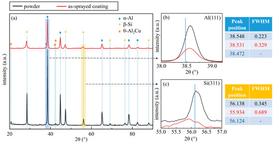
Figure 5.
XRD patterns of the powder and coating. (a) Al-25Si-4Cu-0.9Mg powder and Al-25Si coating; (b) Al(111) diffraction peak; (c) Si(311) diffraction peak.
The width at half maximum (FWHM) in Figure 5b,c represents the grain size. The larger the value is, the smaller the grain size is. It can be seen that the full width at half maximum (FWHM) of Al (111) and Si (311) both increased, and the grain size decreased, indicating that the fast-cooling rate of SAPS limited the grain growth. Thus, the Al-25Si coating exhibited smaller grain sizes of Al and Si than that of the Al-25Si-4Cu-0.9Mg powder.
3.2. Mechanical Properties of Inner Pore Al-25Si Coating
3.2.1. Microhardness of Inner Pore Al-25Si Coating
Hardness is the resistance of a material to mechanical action, such as scoring, pressing or grinding. As a kind of indentation hardness, microhardness reflects the resistance of the material to the indentation of the load less than 0.2 kgf. In general, the wear resistance of the coating is positively related to the hardness, that is, the higher the hardness, the wear resistance.
He [26] compared the Vickers hardness and Si phase size of Al-25Si coating prepared by SAPS with that of high-silicon aluminum alloy prepared by other rapid solidification technologies. He find that the inner hole Al-25Si coating prepared by the SAPS exhibited an average microhardness of 267.09 ± 14.85HV0.2, which is much higher than that of high-silicon aluminum alloys prepared by other rapid solidification techniques, including rapid solidification-powder metallurgy technology (RS-PM), the solidified alloy of spin-quenched strips (MSRC), spray deposition and hot extrusion (SF(E)), selective laser melting technology (SLM), vacuum plasma spraying (VPS) and conventional casting process (CCP).
The excellent microhardness of inner hole Al-25Si coating prepared by the SAPS was mainly due to the three structural changes that occurred during the SAPS process. Firstly, a large number of solute silicon atoms were dissolved in the matrix α-Al lattice, and the formed supersaturated solid solution would provide a strain field due to the large difference between the radii of aluminum atoms and silicon atoms, which leading to the interaction with dislocations to harden the coating [33]; secondly, the XRD results indicated that the grains of Al and Si in the coating after the SAPS were refined, which increased the grain boundary area and effectively prevented the slippage and deformation [34]; thirdly, the relative content of silicon in the Al-25Si coating increased due to the evaporation of Al and Mg elements during the SAPS.
3.2.2. Bonding Strength of Inner Hole Al-25Si Coating
Owing to the differences in the thermodynamic properties and lattice types, the bonding between the coating and the substrate is a typical interfacial bonding of heterogeneous materials, presenting a low bonding strength. However, the aluminum alloy cylinder block and the high silicon aluminum coating exhibited similar thermodynamic properties, and the formation of a micro-metallurgical bond in the interface would effectively improve the bond strength.
The cohesive strength of the coating itself is generally higher than the bonding strength between the coating and the substrate, and thus the damage and peeling of the coating mostly occurs at the junction [35]. Figure 6 shows the stress–strain curve obtained from the tensile test. It can be seen that the bonding strengths of the coatings are 50.4 MPa, 45.0 MPa, and 37.0 MPa, respectively, and the average bonding strength is 44.1 MPa.
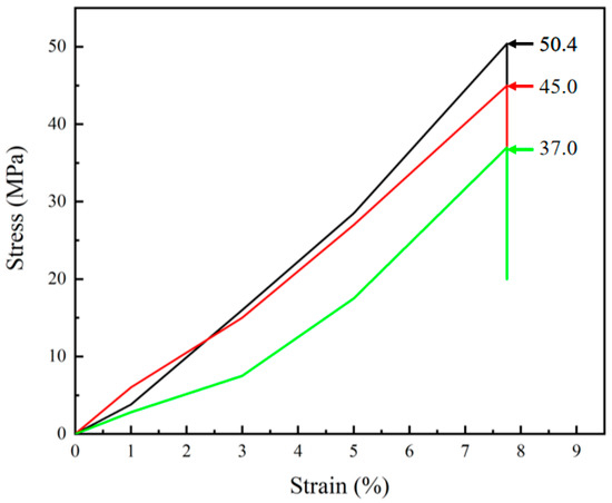
Figure 6.
Stress–strain curves obtained by tensile tests.
The macroscopic fracture morphology shown in Figure 7 indicated that the fracture position was located at the junction and the substrate. In order to further confirm the fracture position, the cross-section of the coating was corroded with Keller reagent, and then observed by SEM at a high-magnification. Figure 8 shows the morphologies of the coating before and after the etch. It can be observed that the Al-25Si coating was closely bonded with the substrate; meanwhile, cracks can be seen inside the substrate, which are due to the large residual stress on the subsurface of the substrate induced by high-speed alumina particles during the sandblasting pretreatment. Additionally, the accumulation and release of heat during the spraying also produced a large thermal stress.
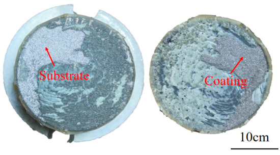
Figure 7.
Section morphology of tensile specimen.
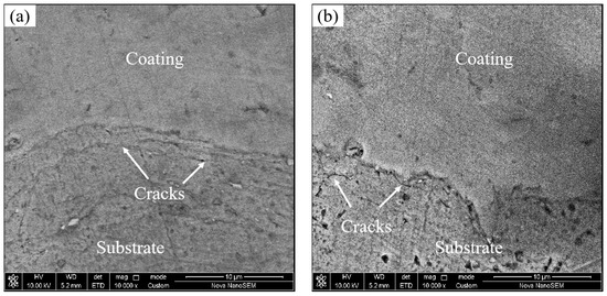
Figure 8.
The microstructure of the interface between the coating and substrate: (a) Uncorroded coatings; (b) coating after the corrosion.
3.3. Wear Resistance of Inner Hole Al-25Si Coating
The friction and wear experiment designed in this paper is mainly to simulate the working condition of the piston ring of a certain type of heavy-duty diesel engine at the top dead center of the cylinder liner. Usually, the piston ring is in the state of high temperature boundary lubrication, semi-dry friction or even dry friction at the top dead center position, and because the speed is almost 0, it is in the boundary lubrication state under the condition of low speed and heavy load, resulting in large friction resistance [36]. Therefore, the selection of friction and wear conditions in the experiment mainly includes the following three aspects:
- (a)
- Choice of load
When the piston ring is at the top dead center, its motion speed is almost zero, and the lubricating oil film is almost broken, so there is almost no lateral friction between the piston ring and the cylinder liner, and the radial load is mainly generated by the detonation gas. According to the size of the piston ring of this type of engine (piston ring height 2.2 mm) and the maximum explosion pressure of the combustion chamber (16 MPa), the pressure per unit arc length of the outer diameter of the piston ring can be obtained by Equation (1) as 35.2 N.
LCA × PCP = l × w × PCP = Load
In the formula: LCA (liner contact area) represents the actual contact area of the counter-grinding pair; l and w are the arc length and ring width of the piston ring in the contact area, respectively, and PCP (peak cylinder pressure) is the maximum burst pressure on the inner wall of the cylinder.
Then, according to the Hertzian contact stress calculation formula under the condition of line-surface contact, the Hertzian contact stress generated by the piston ring at the top dead center position can be calculated to be 1–3 × 10⁸ Pa. According to the contact stress, combined with the Hertzian contact stress calculation formula under the condition of ball-disk contact, it can be deduced that the reasonable applied load is 20 N, and the contact stress at this time is 1.01 × 10⁹ Pa, which is much larger than the actual cylinder liner piston ring contact stress value.
- (b) Selection of reciprocating frequency and stroke
This paper refers to the design experiment of the piston ring working condition of a certain type of heavy-duty engine. In the design parameters, the average speed of the piston is set to be 13.43 m/s, and during the actual movement of the piston ring at the top dead center, since the speed gradually tends to 0, the most worn area near top dead center is about 10 mm. Therefore, the reciprocating frequency and formation of the friction and wear test are set to 10 Hz and 0.8 mm, respectively, that is, the total stroke is 16 mm, and the average movement speed is 16 mm/s, which basically conforms to the service conditions of the engine piston ring.
- (c) Selection of lubrication method and temperature
Generally speaking, the ideal working temperature of lubricating oil is 73.9–93.3 °C. However, in actual working conditions, due to high temperature gas and friction flash temperature, the temperature here is often far beyond the ideal working range, and the viscosity of lubricating oil decreases and becomes thinner. Even exceeding the flash temperature of the oil, coke and other phenomena appear, and the lubricating effect is significantly reduced. In this experiment, on the one hand, since the working temperature of the engine is usually 100–150 °C, the temperature of the platform in the experiment is set to 120 °C; before friction and wear, three drops of lubricating oil (about 0.2 mL) were dropped on the contact surfaces of the upper and lower samples, and no more drops were dropped during the whole test process.
3.3.1. Friction Coefficient and Wear Volume
The wear of the engine cylinder liner and piston was evaluated with oil lubrication at 120 °C. The swing device for the SRV-4 fretting friction and wear tests was shown in Figure 9a. Figure 9b presents the friction coefficient of the inner hole Al-25Si coating, and Figure 9c,d shows the wear scar morphology, width, depth and volume of the inner hole Al-25Si coating and the YL113 substrate, respectively.
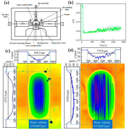
Figure 9.
Friction and wear performance test: (a) swing device of SRV-4 friction and wear test device; (b) friction coefficient of inner hole Al-25Si coating; (c) three-dimensional morphology and size of wear marks of inner hole Al-25Si coating; (d) 3D morphology and size of wear marks on YL113 matrix.
According to the analysis of the friction coefficient curve, the wear process could be divided into three stages. The initial wear stage is that the grinding ball begins to apply load on the Al-25Si coating, and directly contacts the rougher surface, resulting a large friction coefficient close to 0.35. The second wear stage is that the roughness of the wear surface remains in a relatively stable value under the action of the grinding ball and lubricating oil, with the friction coefficient basically unchanged at about 0.19. The third stable wear stage is that the repeated sliding of the grinding ball produces cracks, grooves and wear debris on the wear track, leading to a certain fluctuate of the contact surface roughness and friction coefficient around 0.20.
In general, the inner hole coating exhibited a small and stable average friction coefficient around 0.203, mainly due to the formation of a fluid film of the lubricating oil between the grinding ball and the wear surface, which could greatly reduce the adhesion. Meanwhile, the wear debris is taken away to reduce the wear of abrasive particles. However, since the oil temperature of 120 °C, which largely reduced the viscosity of the lubricating oil, the friction state of the coating is combined with dry friction, liquid friction and boundary friction under a load of 20 N. The state generally contained the contact fatigue caused by the dynamic stress field and micro-cutting formed by the movement of abrasive particles. During the wear process, the wear surface was subjected to dynamic stress, resulting in elastic–plastic deformation and furrows formation.
It can be seen from Figure 9c,d, the inner hole Al-25Si coating and the YL113 substrate show the total wear amounts of 2.77 × 10⁻³ mm3 and 6.73 × 10⁻³ mm3, respectively, and the wear scar widths are 654.3 μm and 773.8 μm, respectively. The depths of wear scars are 8.95 μm and 10.633 μm, respectively, and the wear amount is reduced by about 58.9%. Therefore, the inner hole Al-25Si coating could greatly improve the wear resistance of the aluminum alloy cylinder.
3.3.2. Wear Scar Morphology and Wear Mechanism
The wear scars and wear debris of the coating were observed by SEM to further explore the wear mechanism of the inner hole Al-25Si coating under oil lubrication conditions. As can be seen from the low-magnification morphology of the wear scar shown in Figure 10a, a large amount of nano-silicon particles was uniformly distributed on the entire aluminum matrix, which generate a featureless structure, that is the ideal microstructure of high-silicon-aluminum coatings for wear resistance. In addition, the wear scars surface covered by the furrows and a few wear debris adhered, indicating that the wear mechanism of the coating was mainly furrow cutting under oil lubrication conditions. The high-magnification morphology of the wear scars shown in Figure 10b indicated that microgrooves, slivers delamination [37] and exfoliation pits of the large-grained Si phase coexisted on the worn surface of Al-25Si coatings. There are two main reasons for the formation of micro-grooves, one is the repeated extrusion of the grinding ball on the aluminum matrix, and the other is that the falling off hard silicon phase participates in the wear; The exfoliation pits of the large-grained silicon phase are mainly due to the fact that the broken unmelted silicon phase splashes together during the spraying process, which becomes an inherent defect inside the coating, and at the same time lacks the connection of the aluminum phase, so the combination is relatively weak. The silicon phase particles fall off under the action of the normal stress and shear stress of the grinding ball. Therefore, the coating wear mechanism also included three-body abrasive wear, and a small amount of wear debris was taken away by the lubricating oil.
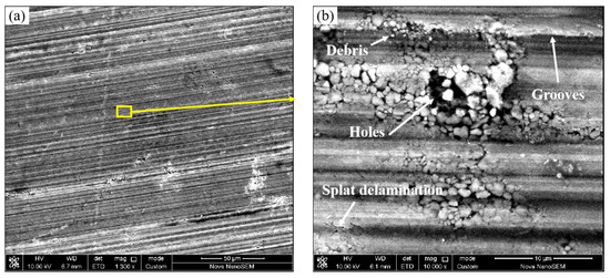
Figure 10.
SEM images of worn surfaces of the inner hole coatings: (a) 1300; (b) 10,000.
The morphology and elements of the wear debris of the inner hole Al-25Si coating were further analyzed and shown in Figure 11 and Table 3. A scratch (marked by the yellow line) caused by the exfoliated hard silicon phase can be clearly observed. The EDS element analysis of Points 1–3 indicated that the Points 1–3 exhibited high contents of silicon element, which was determined to be the exposed hard Si phase during the friction and wear. The high-silicon-alumina coating is mainly composed of α-Al matrix and dispersed β-Si hard phase, belonging to a typical soft matrix with a large amount of dispersed hard points. Thus, the material loss mechanism mainly included the shedding of the hard phase, the plowing of worn surfaces and the adhesion loss of the soft substrate. Under the action of the grinding ball stress, the hard and brittle β-Si phase is easily broken off or directly pulled out from the α-Al matrix. However, the α-Al phase is not prone to adhesive wear under the action of lubricating oil, it would plastically deform under the action of contact stress from the grinding ball and generate furrows; meanwhile, the contact fatigue would occur under the repeated rolling of the grinding ball. Finally, the wear debris being taken away by the lubricating oil or pressed back to the wear surface.

Figure 11.
Debris morphology of the inner hole coating.
Table 3.
EDS results of the feature points (wt.%).
It is worth noting that the oxygen element was detected in Points 1–3, suggesting the possible existence of oxidative wear. Thus, elemental line scan analysis was performed on the worn and unworn surfaces of the inner hole Al-25Si coating under oil bath. As can be seen from the distribution curve of oxygen element shown in Figure 12, due to the existence of furrows, the worn area of the surface increased, which resulting in slightly higher oxygen content. However, the unworn and worn surfaces displayed similar oxygen contents, suggesting no serious oxidative occurred on the worn surface. This might be because the lubricating oil could isolate the air and thus greatly weaken the oxidative wear.
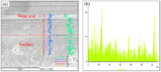
Figure 12.
(a) Element line scan distribution of worn and unworn areas; (b) oxygen element line scan distribution.
Therefore, the wear mechanisms of the inner hole Al-25Si coating under oil lubrication conditions mainly included the furrow cutting, extrusion spalling and three-body abrasive wear in the two-body abrasive wear, and no serious oxidative wear occurred.
4. Conclusions
The inner hole supersonic plasma spraying was performed a wear-resistant high-silicon aluminum coating (Al-25Si) on the YL113 aluminum alloy. The results indicated that the inner hole Al-25Si coating displayed excellent mechanical properties and tribological properties, which can effectively improve the friction and wear properties of YL113 aluminum alloy under oil lubrication conditions. After the spraying with inner pore SAPS, the size of the silicon phase is obviously refined and the shape became small spherical particles. The copper element is over-dissolved into aluminum matrix, and silicon element increased. Compared with the high-silicon aluminum alloys prepared by rapid solidification technologies such as RS-PM, the inner-pore Al-25Si coating prepared by inner-pore SAPS exhibited a smaller silicon phase size and a higher Vickers hardness, with the average hardness of 267.09 ± 14.85HV0.2. In addition, the average bonding strength of the inner-pore Al-25Si coating can reach 44.1 MPa, with the fracture position mainly locating at the interface between the substrate and the coating. Under the oil lubrication at 120 °C, the average friction coefficient of the inner hole Al-25Si coating reached 0.20, and the total wear amount was 2.77 × 10⁻³ mm3, which is lower than that of the YL113 aluminum alloy substrate for 58.9%. The wear mechanism of the coating was mainly attributed to the furrow cutting, extrusion and spalling in two-body abrasive wear, three-body abrasive wear and a small amount of oxidative wear.
Author Contributions
Methodology, G.M. and Z.X.; Project administration, M.L. and H.W.; Supervision, X.Z.; Writing—original draft, Q.P.; Writing—review & editing, Y.H. All authors have read and agreed to the published version of the manuscript.
Funding
This work was supported by the National Natural Science Foundation of China (Grant No. 52130509, 52075542 and 52105235).
Acknowledgments
Authors would like to thank Beijing Sunspray New Materials Co., Ltd. (Beijing, China) for providing high-quality Al-25Si-4Cu-0.9Mg alloy powders.
Conflicts of Interest
The authors declare no conflict of interest.
References
- Lin, X.D.; Lu, J.B.; Sun, J.; Peng, M.; Zhang, R. Fabrication of the all-aluminum engine cylinder and the treatment process of the internal surface of the cylinder liner. Light Alloy. Process. Technol. 2018, 46, 46–50. [Google Scholar]
- Wang, Z.T. Russia launched the world’s first all-aluminum aircraft engine. Light Alloy. Process. Technol. 2018, 46, 24. [Google Scholar] [CrossRef]
- Miller, W.S.; Zhuang, L.; Bottema, J.; Wittebrood, A.J.; De Smet, P.; Haszler, A.; Vieregge, A. Recent development in aluminium alloys for the automotive industry. Mater. Sci. Eng. A 2000, 280, 37–49. [Google Scholar] [CrossRef]
- Reyes, R.V.; Bello, T.S.; Kakitani, R.; Costa, T.A.; Garcia, A.; Cheung, N.; Spinelli, J.E. Tensile properties and related microstructural aspects of hypereutectic Al-Si alloys directionally solidified under different melt superheats and transient heat flow conditions. Mater. Sci. Eng. A 2017, 685, 235–243. [Google Scholar] [CrossRef]
- Li, Z.M.; Sun, X.F.; Song, W. Research on Surface Welding Repair and RoUing Strengthening Process on Inner HoIe Parts of Equipment. J. Armored Forces Eng. Coll. 2014, 28, 92–96. [Google Scholar]
- Samuel, A.M.; Garza-Elizondo, G.H.; Doty, H.W.; Samuel, F. Role of modification and melt thermal treatment processes on the microstructure and tensile properties of Al-Si alloys. Mater. Des. 2015, 80, 99–108. [Google Scholar] [CrossRef]
- Lin, X.; Liu, C.; Zhai, Y.; Wang, K. Influences of Si and Mg contents on microstructures of Al–xSi–yMg functionally gradient composites reinforced with in situ primary Si and Mg2Si particles by centrifugal casting. J. Mater. Sci. 2011, 46, 1058–1075. [Google Scholar] [CrossRef]
- Lin, X.; Liu, C.; Xiao, H. Fabrication of Al-Si-Mg functionally graded materials tube reinforced with in situ Si/Mg2Si particles by centrifugal casting. Compos. Part B Eng. 2013, 45, 8–21. [Google Scholar] [CrossRef]
- Mehran, Q.M.; Fazal, M.A.; Bushroa, A.R.; Rubaiee, S. A critical review on physical vapor deposition coatings applied on different engine components. Crit. Rev. Solid State Mater. Sci. 2018, 43, 158–175. [Google Scholar] [CrossRef]
- Zhai, Y.B.; Liu, C.M.; Wang, K.; Zou, M.; Xie, Y. Characteristics of two Al based functionally gradient composites reinforced by primary Si particles and Si/in situ Mg2Si particles in centrifugal casting. Trans-Actions Nonferrous Met. Soc. China 2010, 20, 361–370. [Google Scholar] [CrossRef]
- Lin, X.D.; Liu, C.M.; Lü, X.J. Effects of Si and Mg contents on the structures and wear resistance of centrifugal Al-xSi-yMg composites reinforced with in situ particles. J. Compos. Mater. 2013, 30, 155–164. [Google Scholar]
- Lin, X.D.; He, T.; Lu, J.B.; Ye, J.C. Manufacturing Technology of the Water-Cooled Aluminum Alloy Engine Cylinder Liner/Body and its Heat Transferring Behavior. Spec. Cast. Nonferrous Alloy. 2016, 36, 345–348. [Google Scholar]
- Lin, X.D.; He, T. Preparation Technology of Aluminum Alloy Engine Cylinder Liner-Cylinder Body and Their Heat Transfer Performance. Foundry 2016, 65, 119–123. [Google Scholar]
- Villafuerte, J. Plasma transferred wire arc process fortifies aluminum engine blocks. Adv. Mater. Process. 2014, 172, 37–38. [Google Scholar]
- Kramer, M.S.; Rivard, C.J.; Koltuniak, F.A. Thermally Sprayed Aluminum-Bronze Coatings on Aluminum Engine Bores. U.S. Patent 5,080,056, 1992. [Google Scholar]
- Ichikawa, H.; Nakada, N.; Yajima, J. The New High-Performance V6 Gasoline Turbocharged Engine from NISSAN; SAE Technical Paper 2009-01-1067; SAE International: Warrendale, PA, USA, 2009. [Google Scholar]
- Furumata, S.; Kakinuma, T.; Tochiki, H. Development of New 3.5 L V6 Turbocharged Gasoline Direct Injection Engine. In Advances in Turbocharged Racing Engines; SAE International: Warrendale, PA, USA, 2019; pp. 171–186. [Google Scholar]
- Hwang, K.; Hwang, I.; Lee, H.; Park, H.; Choi, H.; Lee, K.; Kim, W.; Kim, H.; Han, B.; Lee, J.S.; et al. Development of New High-Efficiency Kappa 1.6 L GDI Engine. In SAE 2016 World Congress and Exhibition; SAE International: Warrendale, PA, USA, 2016. [Google Scholar]
- Hahn, M.; Fischer, A. Characterization of thermally sprayed micro- and nanocrystalline cylinder wall coatings by means of a cavitation test. Proc. Inst. Mech. Eng. Part J J. Eng. Tribol. 2009, 223, 27–37. [Google Scholar] [CrossRef]
- San, Y.L.C. Produce of Aluminium Complex Electroplating Cylinder. CN Patent 01130934.2, 27 August 2001. [Google Scholar]
- DaimlerChrysler, A.G. Coating of Cylinder Walls of Internal Combustion Engine with Aluminum-Silicon Alloys or Aluminum Silicon Composites. U.S. Patent 6,080,360, 27 June 2000. [Google Scholar]
- Alshmri, F. Rapid Solidification Processing: Melt Spinning of Al-High Si Alloys. Adv. Mater. Res. 2011, 383–390, 1740–1746. [Google Scholar] [CrossRef]
- Qian, L.; Lin, J.; Xiong, H. A Fitting Formula for Predicting Droplet Mean Diameter for Various Liquid in Effervescent Atomization Spray. J. Therm. Spray Technol. 2010, 19, 586–601. [Google Scholar] [CrossRef]
- Cava, R.D.; Bolfarini, C.; Kiminami, C.S.; Mazzer, E.M.; Botta Filho, W.J.; Gargarella, P.; Eckert, J. Spray forming of Cu-11.85 Al-3.2 Ni-3Mn (wt%) shape memory alloy. J. Alloy. Compd. 2014, 615, 602–606. [Google Scholar] [CrossRef]
- Nagarajan, B.; Hu, Z.; Song, X.; Zhai, W.; Wei, J. Development of micro selective laser melting: The state of the art and future perspectives. Engineering 2019, 8, 37–44. [Google Scholar] [CrossRef]
- He, P.F.; Tang, L.; Ma, G.Z.; Wang, H.D.; Chen, S.Y.; Liu, M.; Ding, S.Y.; Bai, Y.; Tang, J.J.; He, D.Y. Understanding the formation mechanism of supersonic atmospheric plasma sprayed in-situ hypereutectic Al-25 wt.%Si coating with nanostructured coupled eutectic: From powder, in-flight droplet, splat to coating. Appl. Surf. Sci. 2020, 530, 147–246. [Google Scholar] [CrossRef]
- Wang, H.J.; Liu, M.; Li, X.Q.; Ma, G.Z. The Development of Internal Plasma Spraying Device. J. Therm. Spray Technol. 2011, 3, 10. [Google Scholar]
- Zhang, G.Z.; Wang, H.J.; Zhao, W.H. High-Energy Inner Hole Plasma Spray Gun. Beijing: CN 2,038,814, 6 July 1989. [Google Scholar]
- Dong, X.Q.; Zhang, Y. Application of internal plasma arc spraying on reinforcing the cylinder bore of engine. Weld. Technol. 2010, 39, 77. [Google Scholar]
- Rong, C.; Shen, B. Nanocrystalline and nanocomposite permanent magnets by melt spinning technique. Chin. Phys. B 2018, 27, 117–121. [Google Scholar] [CrossRef]
- Rajabi, M.; Simchi, A.; Davami, P. Microstructure and mechanical properties of Al-20Si-5Fe-2X(X = Cu, Ni, Cr) alloys produced by melt-spinning. Mater. Sci. Eng. A 2008, 492, 443–449. [Google Scholar] [CrossRef]
- Kang, N.; Coddet, P.; Liao, H.; Baur, T.; Coddet, C. Wear behavior and microstructure of hypereutectic Al-Si alloys prepared by selective laser melting. Appl. Surf. Sci. 2016, 378, 142–149. [Google Scholar] [CrossRef]
- Uzun, O.; Karaaslan, T.; Gogebakan, M.; Keskin, M.U. Hardness and microstructural characteristics of rapidly solidified Al-8-16 wt.% Si alloys. J. Alloy. Compd. 2004, 376, 149–157. [Google Scholar] [CrossRef]
- Gao, B.; Hu, L.; Li, S.; Hao, Y.; Zhang, Y.D.; Tu, G.F.; Grosdidier, T. Study on the nanostructure formation mechanism of hypereutectic Al-17.5 Si alloy induced by high current pulsed electron beam. Appl. Surf. Sci. 2015, 346, 147–157. [Google Scholar] [CrossRef]
- Wang, H.J. A Guide for Thermal Spray Engineers; National Defense Industry Press: Beijing, China, 2010; pp. 35–38. [Google Scholar]
- Bhushan, B. Introduction to Tribology; John Wiley & Sons, National Defense Industry Press: Beijing, China, 2010. [Google Scholar]
- Hartfield-Wünsch, S.E.; Tung, S.C. The Effect of Microstructure on the Wear Behavior of Thermal Spray Coatings; ASM International: Materials Park, OH, USA, 1994; p. 38. [Google Scholar]
Publisher’s Note: MDPI stays neutral with regard to jurisdictional claims in published maps and institutional affiliations. |
© 2022 by the authors. Licensee MDPI, Basel, Switzerland. This article is an open access article distributed under the terms and conditions of the Creative Commons Attribution (CC BY) license (https://creativecommons.org/licenses/by/4.0/).