1. Introduction
The structural analysis of historic buildings is one of the greatest challenges currently faced by structural engineers, particularly when assessing their stability and safety [
1,
2]. This complexity is heightened in architecturally singular elements that display hard-to-diagnose pathologies, such as those in the Bullring of the
Real Maestranza de Caballería de Ronda (RMR), which is the focus of the present study. In addition to their inestimable cultural value, historic buildings are complex structural systems that demand specific approaches to ensure their long-term conservation [
3].
In this context, sophisticated finite-element (FE) models are routinely employed to simulate structural behaviour [
4]. A major difficulty, however, lies in defining the geometric and mechanical characteristics of these models with sufficient accuracy. Uncertainties in geometry, material properties and degradation state hinder the creation of reliable models. Small changes in such parameters can lead to markedly different results, making careful definition essential [
5]. A primary limitation in heritage structural assessment lies in the mechanical characterisation of historic materials, where spatial heterogeneity makes comprehensive representation challenging through limited testing campaigns.
Non-destructive techniques (NDTs) are therefore crucial for narrowing the gap between numerical predictions and real structural behaviour. Notably, 3D laser scanning has revolutionised heritage documentation, providing highly accurate models that capture deformations accumulated over time [
6].
Dynamic characterisation techniques based on modal analysis have also proved highly effective for assessing historic buildings. Operational modal analysis (OMA) can identify global modal parameters (natural frequencies, mode shapes and damping ratios) using only ambient excitation [
7]. Experimental modal analysis (EMA), together with sonic tests (STs), offers a more detailed view of specific elements under controlled excitation. EMA is particularly useful for detecting local damage, while sonic tests, based on the propagation of elastic waves, allow Young’s modulus and Poisson’s ratio to be determined without removing material [
8,
9]. These data are indispensable for calibrating numerical models of structures subject to high levels of uncertainty.
Integrating these methodologies with precise geometric documentation establishes a robust framework for the structural evaluation of architectural heritage [
10]. Calibrating numerical models with experimental data is a critical step in structural assessment [
11], enabling model parameters to be refined and inherent uncertainties to be reduced. This process is fundamental to obtaining reliable predictions of structural behaviour and stability.
Recent developments in heritage structural assessment demonstrate increasing recognition that single-technique approaches are insufficient for comprehensive evaluation of historic buildings. Providakis et al. [
12] successfully integrated operational modal analysis with laser-scanning vibrometry and finite-element model updating for a Byzantine church, demonstrating the effectiveness of combining advanced measurement techniques with numerical calibration. Amer et al. [
13] developed a conservation-oriented approach that synchronises laser scanning, OMA, and nonlinear simulation to define progressive collapse scenarios for complex heritage masonry structures, while Grămescu et al. [
14] presented an analytical framework integrating ultrasonic testing, DRMS, and FEM for prioritising consolidation interventions in historical masonry. Additionally, Zucca et al. [
15] applied multidisciplinary approaches combining structural analysis with seismic assessment for historic buildings, and Saisi et al. [
16] developed integrated procedures combining safety assessment with conservation requirements based on historic research. However, while progress has been made in combining 2–3 techniques, systematic integration of geometric documentation, global and local dynamic characterisation, and comprehensive material testing remains relatively unexplored in heritage assessment applications.
This paper therefore proposes an integrated methodology for the structural diagnosis and stability analysis of the RMR Bullring, built in 1783. Constructed mainly of sandstone ashlar and brick masonry, the building combines a singular geometry with numerous structural pathologies, making it an exceptional case study. This historic building poses particular challenges owing to its unusual geometry and the presence of very slender elements, such as the 136 sandstone columns that form the inner ring. Documented interventions since the nineteenth century have modified the original behaviour of the structure, adding metal struts and bracing systems that testify to persistent stability problems. Previous technical reports have highlighted significant deformations, particularly in the sandstone columns, and called for an urgent stability assessment [
17]. The methodology combines advanced geometric documentation with dynamic characterisation to develop and validate an FE model that accurately evaluates the structure’s current safety. The approach not only identifies elements at risk of collapse but also provides essential data for designing sympathetic strengthening measures.
The remainder of the paper is organised as follows.
Section 2 sets out the general methodology.
Section 3 describes the case study, including architectural features, construction system and current condition.
Section 4 details the experimental campaigns (3D laser scanning, ambient vibration testing (AVT), OMA, EMA and STs).
Section 5 explains the development and updating of the FE model.
Section 6 presents the structural analysis with the calibrated model, including the stability assessment and identification of critical elements. Finally,
Section 7 summarises the main conclusions and outlines future research directions.
2. Methodology
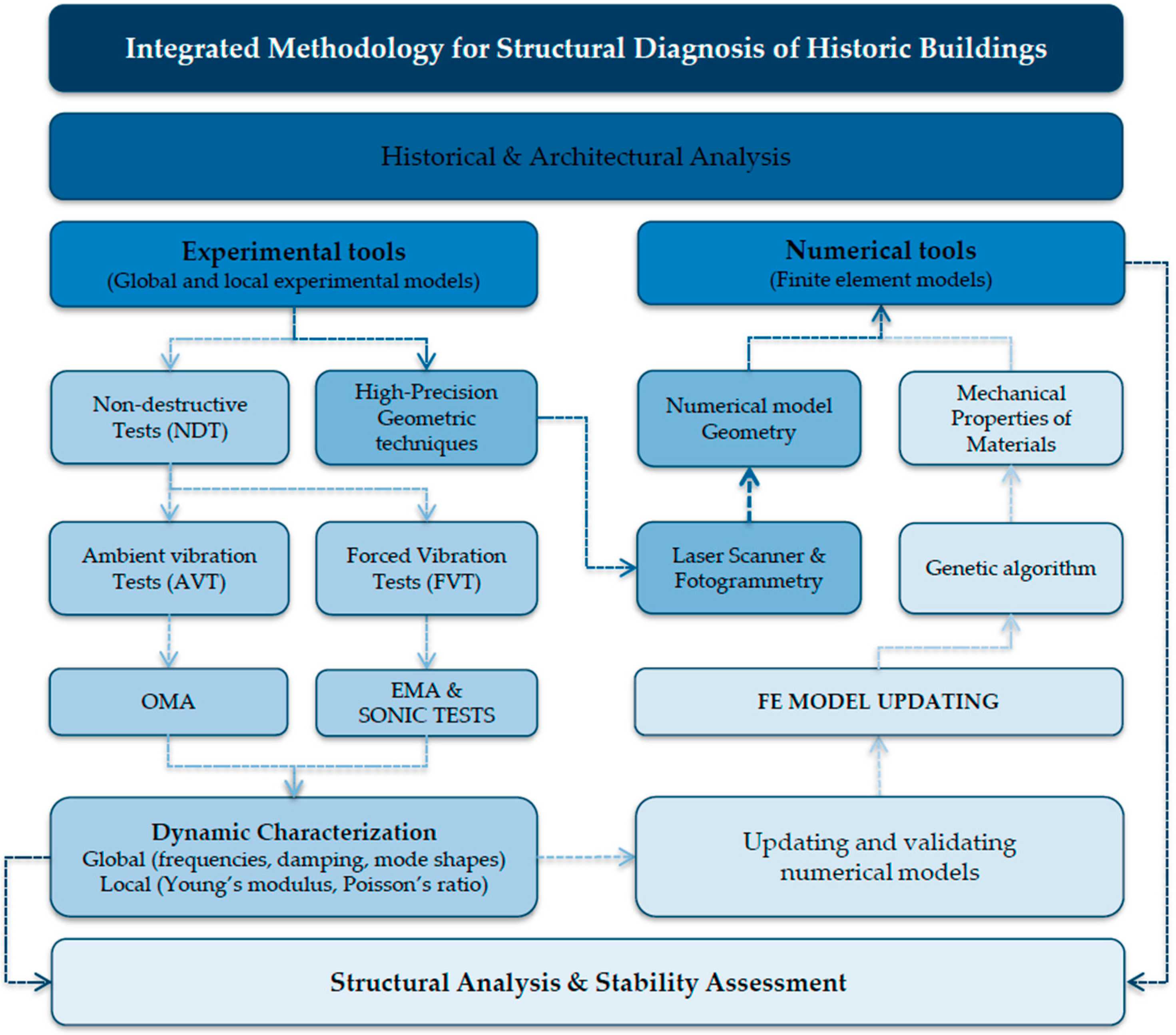
The proposed methodology for the structural diagnosis of historic buildings that exhibit apparent stability problems, exemplified by the RMR Bullring, follows a multidisciplinary workflow that couples state-of-the-art geometric documentation with advanced dynamic characterisation techniques. This systematic, non-destructive protocol is organised into four complementary phases (
Figure 1).
The first phase involves a historical and architectural evaluation of the building, including a critical review of archival documentation, a reconstruction of the construction sequence and an appraisal of past interventions. This background assessment is indispensable for understanding the observed patterns of deformation and decay, and for formulating hypotheses about their underlying causes. Analysing previous repairs also reveals structural alterations that may have modified the building’s original behaviour [
18].
The second phase concerns high-precision geometric documentation via 3D laser scanning. The resulting point cloud captures existing deformations with millimetric accuracy, providing an objective record of the current condition and a sound geometric basis for subsequent analyses [
19,
20,
21,
22]. Conventional topographic techniques are used to cross-check the survey and to establish a consistent reference frame.
The third phase integrates global and local dynamic characterisation. At the global scale, AVT combined with OMA identifies the structure’s natural frequencies, mode shapes and damping ratios using only environmental excitation [
23,
24]. To ensure robust results, the data are processed with two complementary algorithms: enhanced frequency domain decomposition (EFDD) in the frequency domain [
25] and stochastic subspace identification (SSI) in the time domain [
26,
27].
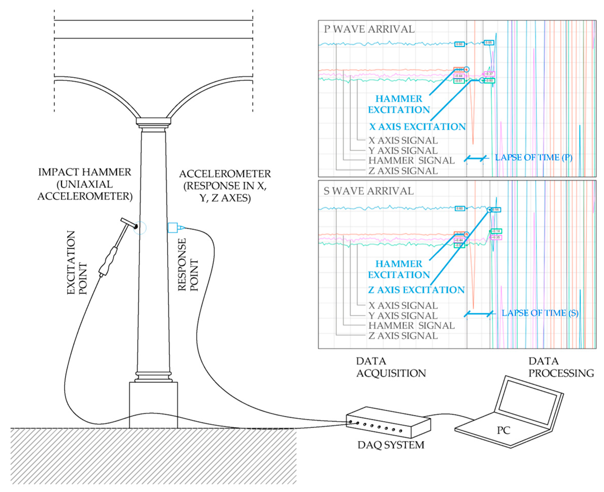
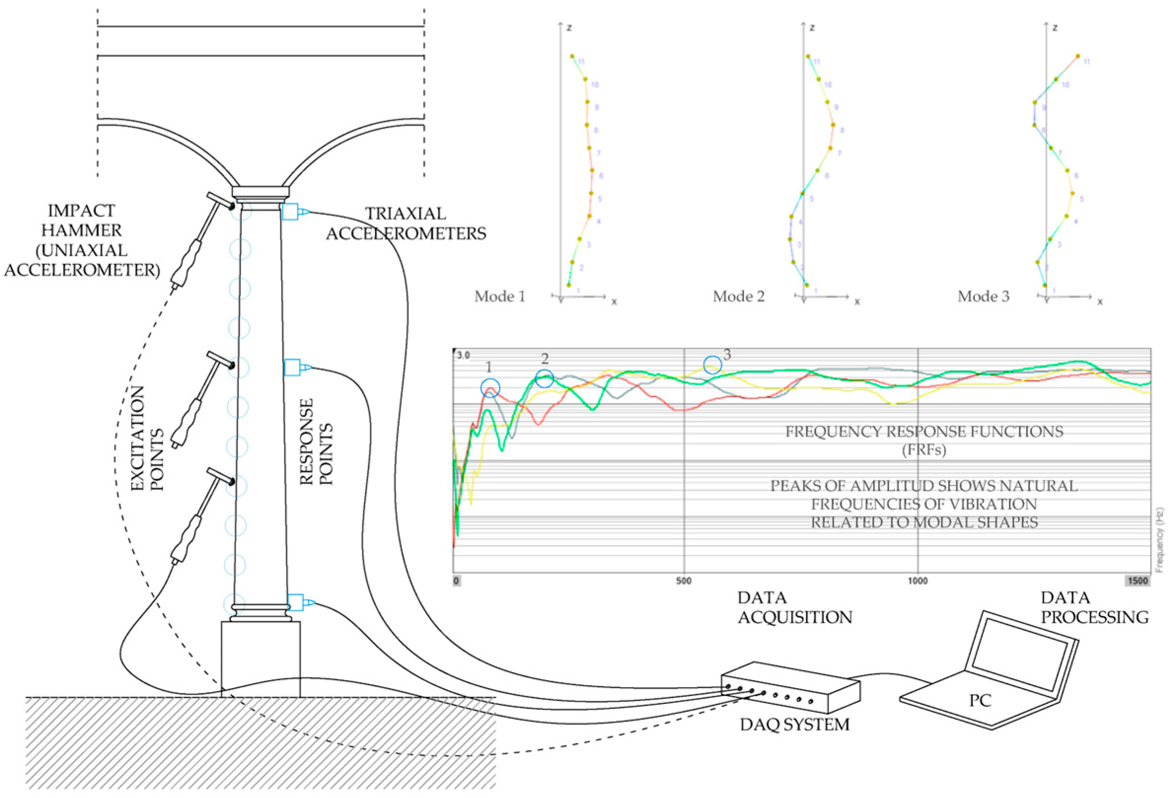
At the local scale, two specialised techniques are deployed: STs and EMA [
28]. Sonic testing, based on the propagation of longitudinal (P-wave) and transverse (S-wave) elastic waves, yields the dynamic Young’s modulus and Poisson’s ratio without coring, by recording the response to controlled impacts with an instrumented hammer [
29,
30]. EMA, in turn, determines the natural frequencies and mode shapes of individual elements under controlled excitation, enabling the detection of localised damage invisible to the naked eye. The combination of global and local techniques therefore furnishes a comprehensive dynamic characterisation, spanning overall structural behaviour and the mechanical properties of critical components.
The fourth phase entails developing and calibrating an FE model [
31]. Starting from the real geometry derived from 3D laser scanning and the mechanical parameters obtained experimentally, a parameter-updating procedure based on genetic algorithms [
32,
33] systematically adjusts the model until an optimal match with the experimental dynamic behaviour is achieved. The objective function minimises the quadratic error between numerical and experimental frequencies while restricting the variation in material parameters to ranges consistent with historic masonry [
11].
The calibrated model is subsequently employed to carry out a stability analysis, assessing the ultimate limit state of equilibrium by calculating load eccentricities and safety factors [
34,
35]. Different load cases, including self-weight and full-occupancy live loads, are considered. Each column is checked individually by comparing the calculated eccentricity with the kern of the cross-section, enabling critical elements to be identified.
This integrated methodology not only pinpoints vulnerable elements and clarifies deformation mechanisms but also underpins evidence-based intervention strategies. The synergy of non-destructive testing and advanced numerical modelling provides a robust tool for diagnosing heritage structures with complex geometries and stability issues [
10]. Validation relies on several criteria: the modal assurance criterion (MAC) between experimental and numerical mode shapes [
36,
37], the agreement between ST-derived moduli and bibliographic values, and the consistency between numerical predictions and in situ observations, thereby ensuring confidence in the ensuing conservation decisions.
Finally, the workflow is designed to be cost-effective, balancing accuracy with practicality so that, within realistic operational, time and budget constraints, a sufficient knowledge level can be attained. The procedure is replicable and scalable, making it suitable for a wide range of heritage buildings while maintaining the scientific and technical rigour required for publication. Compared to conventional heritage assessment approaches that employ multiple techniques sequentially with manual data integration, the proposed methodology preserves high precision through automated point cloud processing and systematically integrates four complementary techniques synergistically. The methodology acknowledges certain inherent constraints and assumptions typical of heritage structural assessment due to the complexity of historic buildings and preservation requirements.
3. Case Study: RMR Bullring
3.1. Historical Background and Heritage Value
The
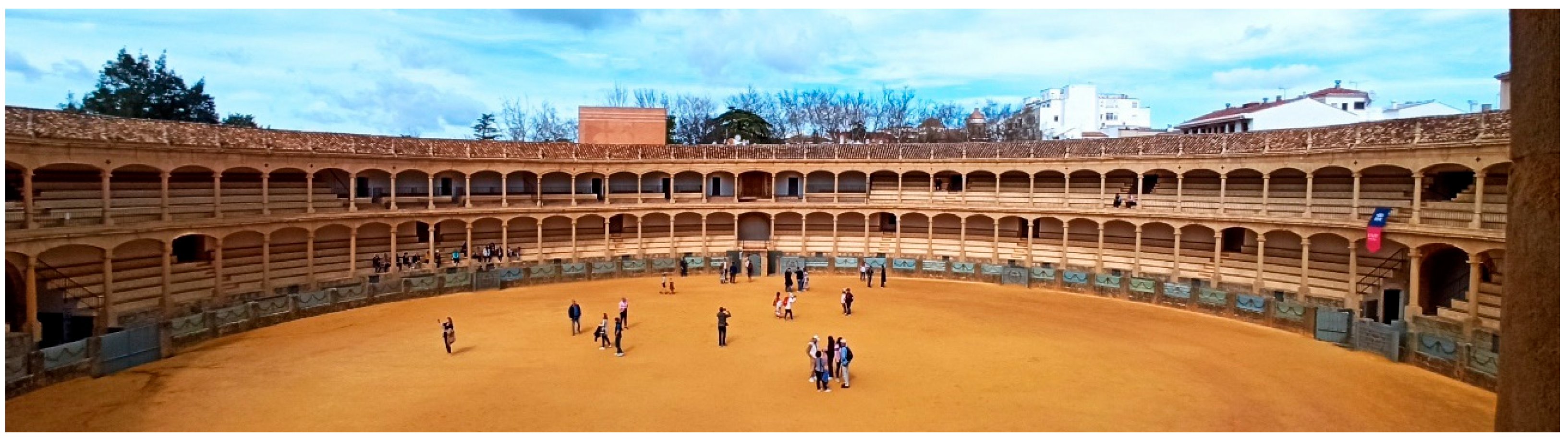
Plaza de Toros de la Real Maestranza de Caballería de Ronda (RMR Bullring) is one of Spain’s most emblematic taurine monuments and a benchmark of eighteenth-century architecture (
Figure 2). Built in 1783, it was the country’s third purpose-built bullring, after Madrid’s
Plaza Mayor (1754) and Seville’s
Real Maestranza (1761). In 1993, the building was designated an Asset of Cultural Interest (BIC) with monument status, a recognition that underscores its exceptional historical, artistic, and cultural value and imposes strict conservation requirements for any intervention [
38].
Throughout its history, the bullring has undergone several structural interventions prompted by persistent stability problems. The most significant include Carlos Lamiable’s 1880 installation of metal struts above the impost course to counteract arch deformation [
39]; José M. Benjumea’s 1947 reconstruction [
40], which replaced the first-floor timber deck with a concrete ribbed slab with ceramic infill blocks and substituted six columns; and the comprehensive 1962 restoration by Francisco Pons-Sorolla and Ramiro Moya Blanco [
41], which removed Lamiable’s struts and introduced a new, but incomplete, bracing system. This historical information proved fundamental for identifying structural elements not visible through conventional inspection, and for understanding changes in structural behaviour resulting from successive interventions, providing essential context for interpreting current pathologies and deformation patterns.
3.2. Architectural Configuration and Structural System
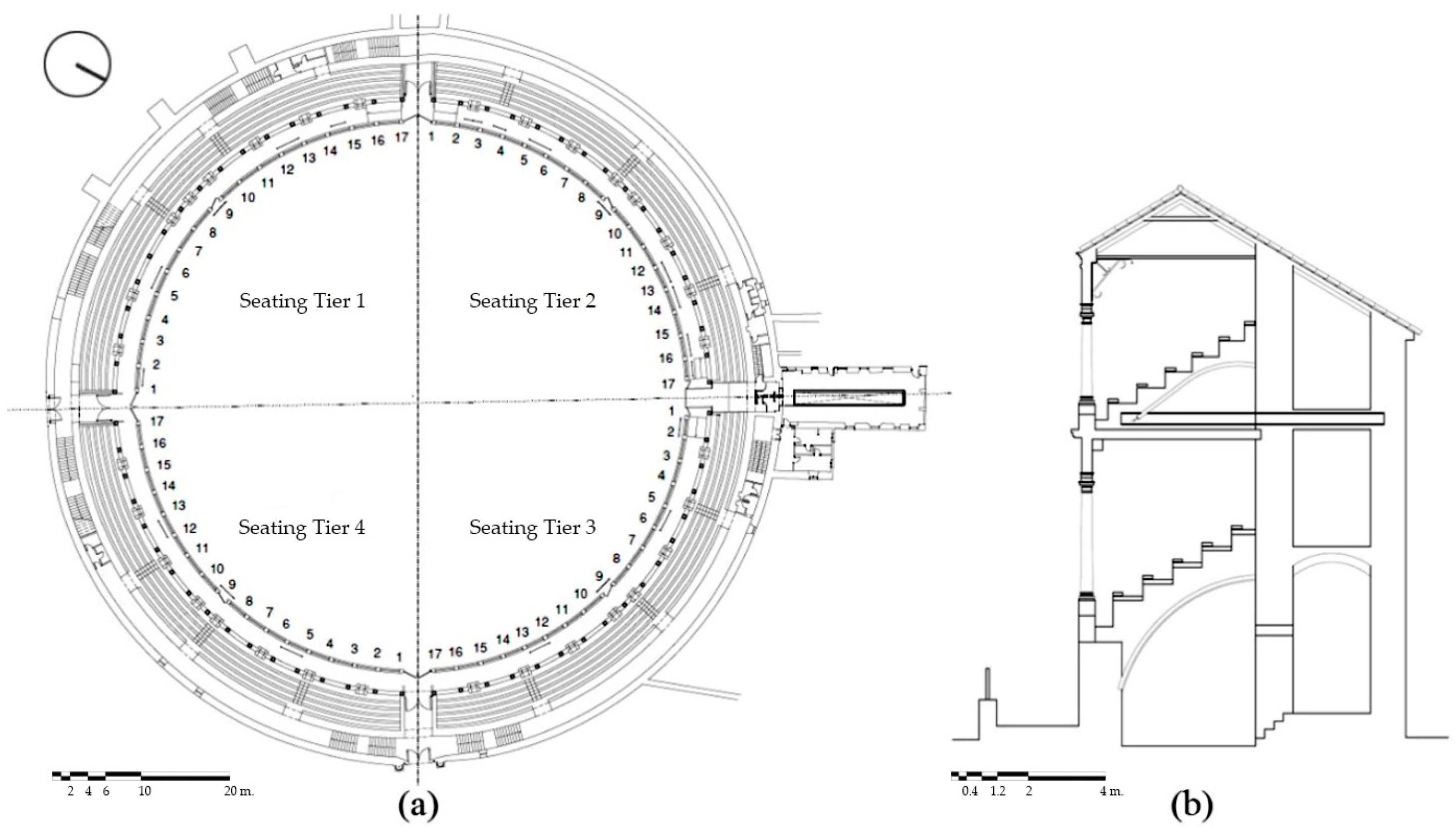
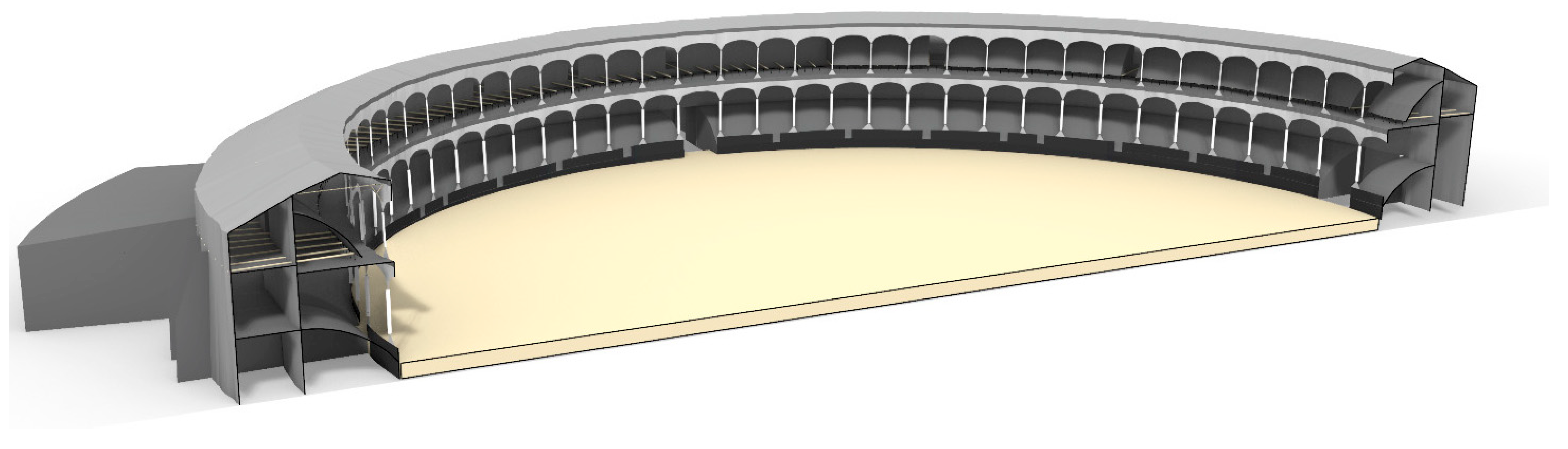
The arena displays the typical geometry of Spanish bullrings: two concentric rings comprising two levels of stands and circulation galleries (
Figure 3). The outer ring hosts galleries on both storeys and is approximately 2.00 m wide, while the inner ring, largely occupied by seating, is about 4.00 m wide. The structure is divided into four sectors (Tiers 1–4), each with slight constructional differences. The structural system comprises sandstone columns, stone masonry arches located in the inner ring, and brick masonry for both the perimeter and intermediate walls. The stone masonry employs traditional ashlar construction with sandstone blocks from the Arroyo del Toro quarry (Málaga, Spain), laid in regular courses with lime-based mortar joints typical of 18th-century Andalusian construction techniques. The arches are developed with approximately 40 cm thickness. The brick masonry walls utilise solid clay bricks arranged in a common bond pattern with lime mortar, characteristic of the period’s construction practices, and are developed in single-wythe construction of approximately 90 cm thickness. The mortar composition consists of a lime binder with local sand aggregates [
42].
The horizontal structure has been substantially altered. The lower stands now rest on a three-leaf brick vault, whereas the upper stands combine several systems: (i) reinforced-concrete ribs carrying only the first two seating rows, (ii) steel-joist slabs between Tier 3, Column 1 and Tier 4, Column 2, and (iii) a mixed solution elsewhere, with a brick vault bearing on the intermediate wall and radial steel beams cantilevered from the heavy outer walls. Deterioration has been recorded at some beam anchorages [
42].
The roof completes the system with double-pitched timber trusses over the stands and timber purlins over the galleries. The original timber-and-steel tie system has suffered progressive decay, with slackening ties and rotten anchor sleepers compromising its stabilising role.
3.3. Current Structural Condition
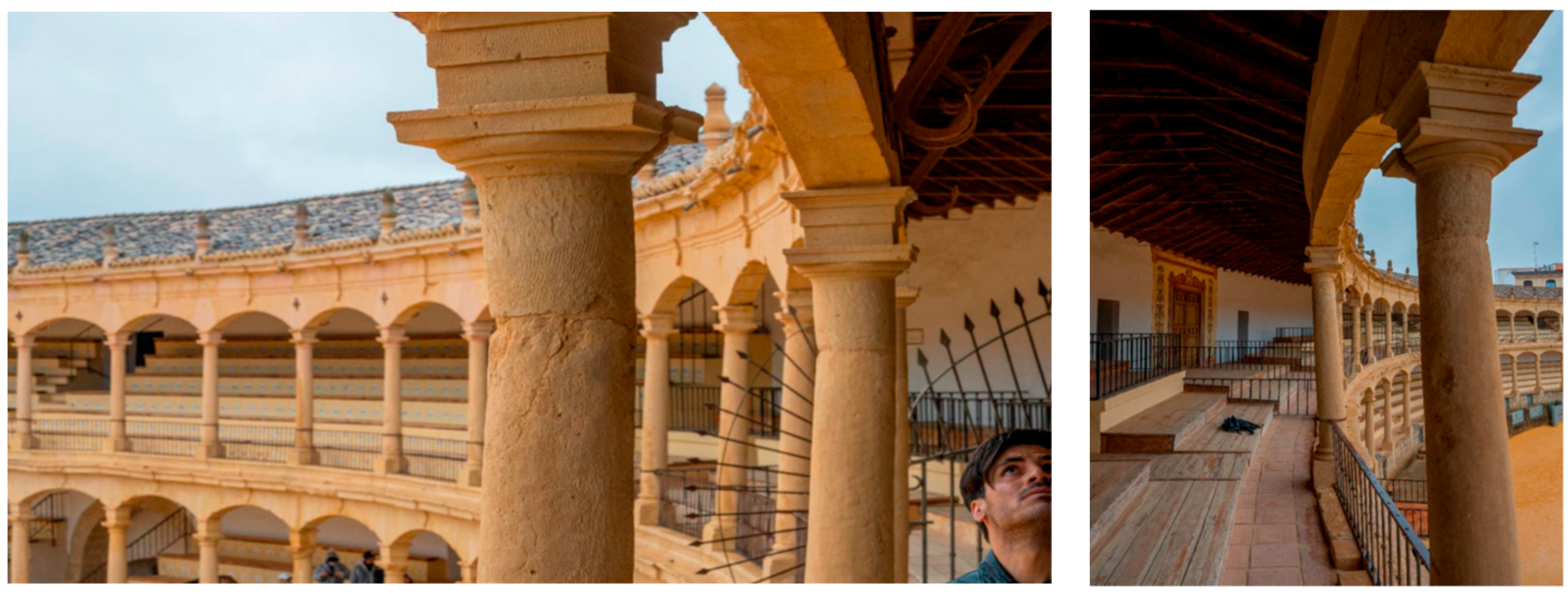
Current surveys reveal significant deformations, especially in the inner ring. Previous pathological studies recorded outward tilts of up to 21 cm in some upper-tier columns, mainly in Tiers 2–4. The deformations show varying orientations and affect both upper and lower stands, suggesting a systemic rather than local problem. The sandstone columns display severe material loss due to weathering, vertical and horizontal cracking, and differential decay according to exposure [
17] (
Figure 4).
Additional observations include misalignments between upper and lower tier columns, bowing of walls, dislodged arch voussoirs wedged with metal shims, and a pronounced kinked profile in the column–lintel ensemble, all indicating a pervasive structural deficiency beyond isolated material deterioration.
Inspection of the roof bracing revealed several completely slack ties and advanced decay in their timber anchor blocks, seriously undermining the system’s ability to resist the horizontal thrust of vaults and arches [
42]. Topographic survey and point cloud data show a global 0.80 m elevation difference between the north-eastern and south-western extremes; nevertheless, structural analysis combined with geotechnical studies found no indications of differential settlement in any zone [
43].
Together, the remarkable geometric singularity, advanced decay, and cultural significance of the RMR Bullring fully justify an integral structural assessment and the development of carefully designed, heritage-compatible strengthening measures.
4. Experimental Tools
This section summarises the experimental campaigns carried out in the RMR Bullring between 2023 and 2024 and the results obtained with complementary geometric and dynamic characterisation techniques, designed to capture the present structural condition, the mechanical properties of the historic materials, and the building’s global and local dynamic behaviour.
4.1. Geometric Documentation: 3D Laser-Scanning Results
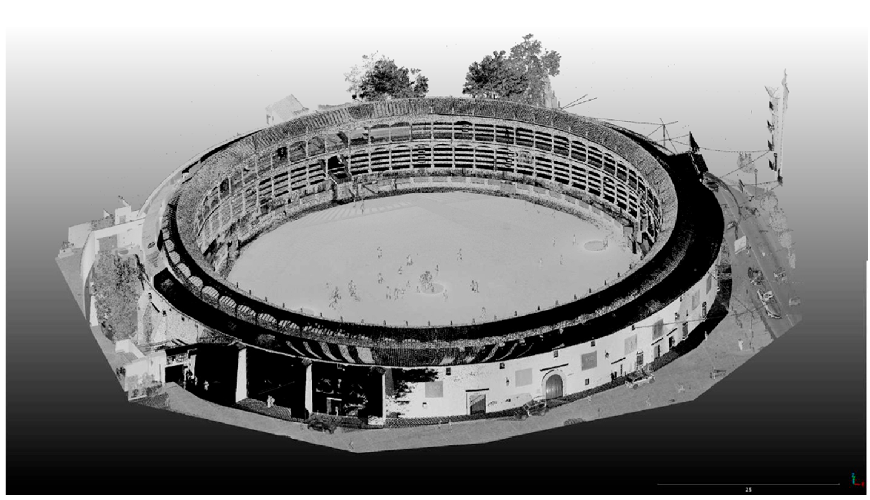
Three-dimensional (3D) laser scanning operates on time-of-flight measurement principles, where laser pulses are emitted toward target surfaces and the return time is measured to calculate precise distances. This technique enables millimetric detection of structural deformations accumulated over time, providing the essential geometric foundation for developing realistic numerical models that preserve the actual deformed state rather than idealised geometries. The 3D laser-scanning campaign, conducted between March and July 2023, comprised more than 150 scan stations strategically distributed around the monument. Its principal purpose was to generate a high-fidelity 3D model capable of identifying and quantifying the accumulated deformations in the structural ensemble and of serving as the geometric basis for the numerical model.
Data acquisition was performed using a Leica RTC360 3D laser scanner with measurement accuracy of ±1 mm, angular accuracy of 6″ and a distance accuracy of ±2 mm. The survey design ensured complete coverage of the building, paying particular attention to previously identified critical areas, notably the inner ring of columns and the perimeter walls.
Data processing and registration were conducted using Leica Cyclone REGISTER 360 software for point cloud alignment and analysis. The processing workflow produced a point cloud at 1 point cm
−1, yielding a model of 1.054 million points (
Figure 5). Rigorous station registration and alignment achieved an estimated overlap error below 1 mm and a global error below 1.5 cm, tolerances sufficient for deformation analysis in historic buildings, enabling tilts and displacements to be detected with the resolution required for reliable structural diagnosis [
44].
In parallel with the 3D laser-scanning survey, laser levelling was carried out in the arena, the lower stands and the upper stands. The campaign revealed a maximum level difference of 0.80 m between the lowest point (south-western sector, Tier 2) and the highest (eastern sector, Tier 4). Topographic results showed specific deformation patterns: outward tilts of up to 0.21 m in upper-tier columns (mainly Tiers 1–4); tilts of up to 0.32 m in the outer wall, particularly in the east; floor-level variations of up to 0.80 m between opposite ends of the building; and misalignments between ground and upper-tier columns exceeding 0.15 m in some cases (
Figure 6).
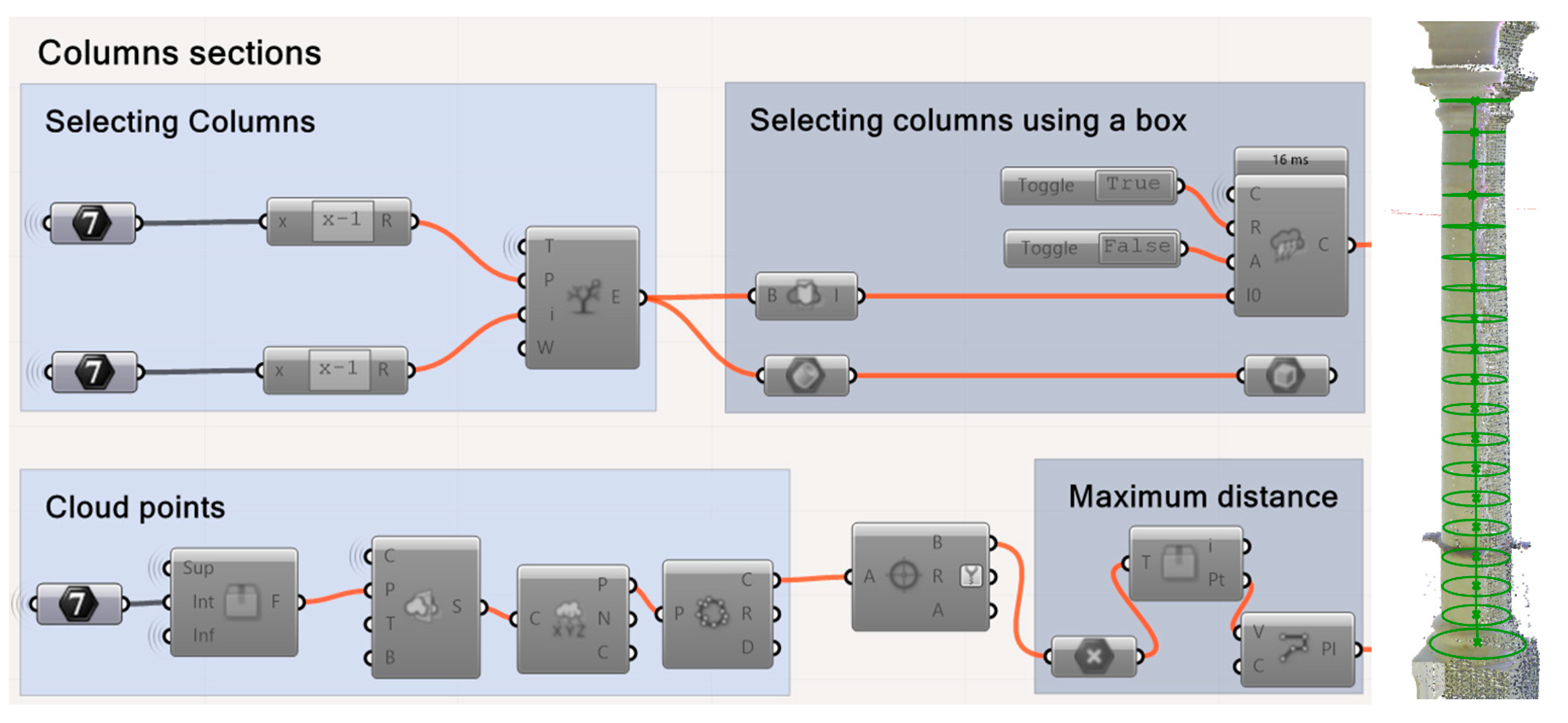
Post-processing of the point cloud employed bespoke routines written in Rhinoceros [
45] and its Grasshopper plugin [
46], representing a critical methodological advancement in the transfer of real deformed geometries to FE models. These scripts constituted the essential bridge between measured reality and numerical simulation, addressing one of the most challenging aspects in heritage structural analysis: the accurate incorporation of accumulated deformations into computational models. The parametric algorithms isolated and segmented the various structural elements, extracted transverse column sections at several heights, determined their deformed axes with millimetric accuracy, quantified tilts and misalignments through vector analysis, and generated simplified geometric models for subsequent FE analysis (
Figure 7). Unlike conventional approaches that approximate heritage buildings using idealised geometries, these automated routines preserved the exact deformed state measured by laser scanning, ensuring that every detected deformation was faithfully translated into the FE model. This systematic incorporation of measured deformed geometry represents a significant methodological contribution. The resulting geometry faithfully reflects the building’s current deformed state and forms the essential foundation for the FE model, enabling reality-based rather than idealised structural modelling.
4.2. AVT and OMA Results
OMA extracts dynamic properties from structures using ambient excitation, revealing global structural flexibility, natural frequencies, and mode shapes that indicate overall behaviour and potential instabilities. Between 1 and 3 March 2023, an AVT campaign was conducted to characterise the global dynamic behaviour of the RMR Bullring. A total of 72 measurement points were distributed in 12 radial sets of six points each (three on the lower tier and three on the upper tier), thus ensuring complete coverage of the main structural elements.
Data were acquired with a KINEMETRICS OBSIDIAN X36 system equipped with eight balanced-force triaxial accelerometers (frequency range 0.01–200 Hz; sensitivity 10 V/g; dynamic range 140 dB; 24-bit resolution). The test adopted a multiple-reference strategy: two accelerometers remained at fixed reference locations while the remaining six were moved sequentially. This scheme yielded twelve 12 min set-ups sampled at 100 Hz, producing roughly 72,000 records per channel. Only environmental excitation, wind, ground micro-tremor, nearby traffic and pedestrian activity was used. The diversity of natural inputs supplied a sufficiently rich frequency content for reliable modal identification.
Signal processing in Artemis Modal Pro [
47] combined two complementary algorithms: enhanced frequency domain decomposition (EFDD) [
25] and stochastic subspace identification (SSI-UPCX) [
26,
27]. Processing algorithm configurations included EFDD frequency resolution of 0.01 Hz with a correlation threshold of 0.8, while SSI stability criteria required frequency stability below 1% and mode-shape correlation above 0.8.
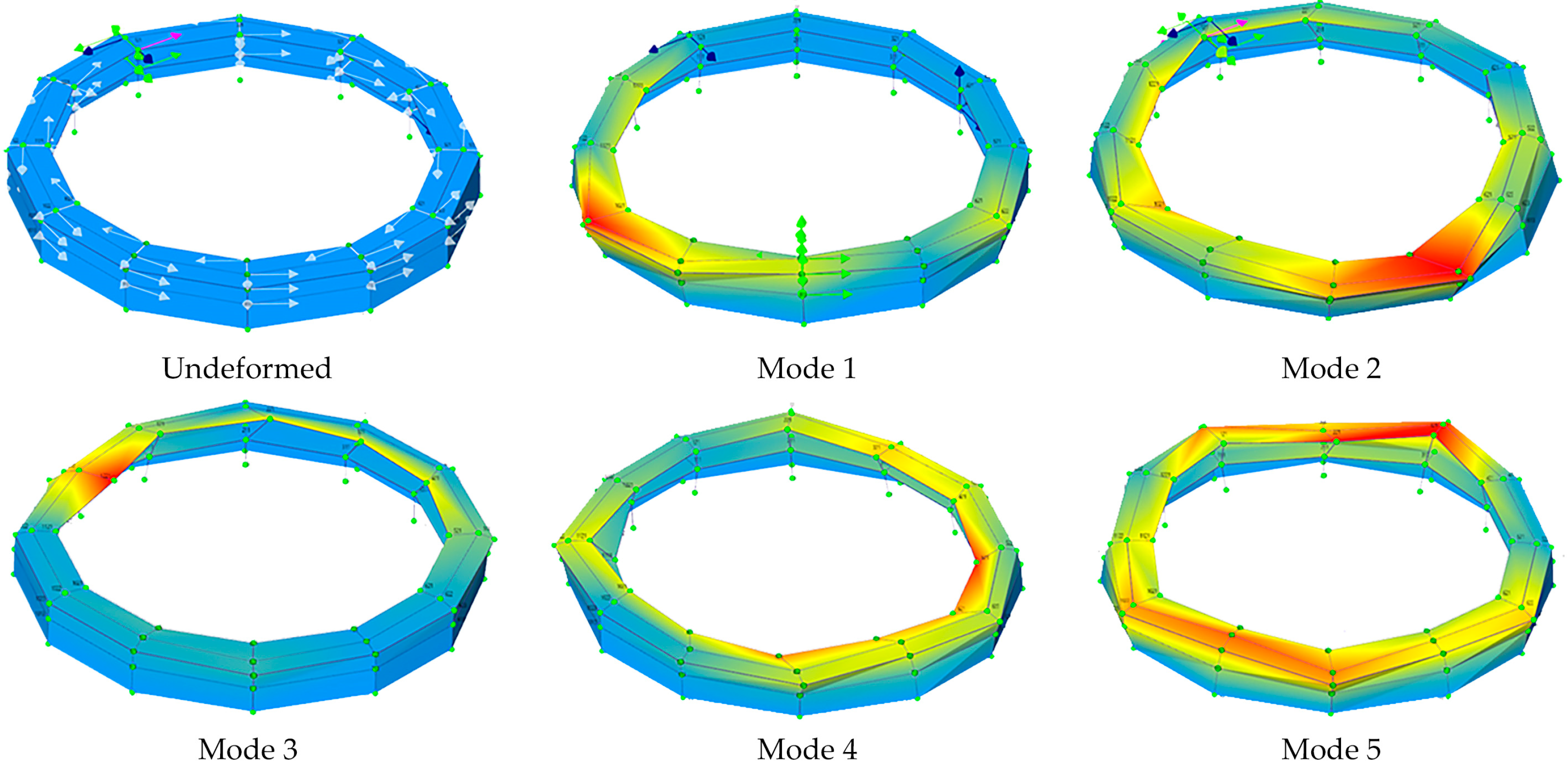
Table 1 compares the frequencies and modal assurance criterion (MAC) values obtained with both techniques. Percentage differences are below 0.7%, and MAC values exceed 0.80, confirming the robustness of the identification. Five global modes were found in the 4.13–5.63 Hz band, all dominated by the upper gallery.
Modal shapes reveal distinct dynamic features (
Figure 8). Mode 1 (4.13 Hz) represents global bending with maximum response in the upper gallery, underlining its relative flexibility. Modes 2 and 3 (≈4.5–4.7 Hz) combine torsion and bending, highlighting stiffness differences between seating tiers. Modes 4 and 5 (≈5.2–5.6 Hz) involve more complex deformations centred on the upper arcade.
A particularly significant observation is that the fundamental modes fall within 3–4 Hz, coinciding with the critical frequency band prescribed by the Spanish Structural Code (
CTE DB-SE) for spectator facilities [
48]. This suggests a potential resonance risk under dynamic crowd loading, which could amplify existing deformations and accelerate deterioration. Detailed modal analysis shows a marked stiffness contrast between the lower and upper galleries, with maximum modal displacements consistently localised in the upper-tier columns and arches. These findings confirm that the upper level is the most flexible and therefore the most vulnerable part of the structure.
4.3. Material Characterisation: STs Results
The ST technique provides quantitative assessment of material degradation and mechanical properties essential for FE model updating. While ultrasonic waves are generally preferred for stone materials, the ST methodology provides sufficient accuracy for obtaining initial reference values for model updating purposes. A systematic and extensive ST campaign examined 36 sandstone columns, nine per tier, as well as the perimeter walls and buttresses, generating a complete mechanical map of the principal structural elements (
Figure 9).
Data acquisition employed a Dewesoft Sirius-8ACC unit capable of high-resolution, multi-channel recording. Controlled impacts were delivered with a Takagi IH-02 instrumented hammer, fitted with an integral uniaxial accelerometer to measure impact force precisely, while the dynamic response was captured by MMF KS903B.100 triaxial accelerometers bonded with elastic putty to avoid surface damage. Signal synchronisation and post-processing were managed in Dewesoft X3. Each element received ≥10 impacts. Time-of-flight analysis of the recorded longitudinal (P) and transverse (S) waves yielded wave velocities, from which elastic parameters were derived:
It should be noted that these relationships are theoretically valid for perfectly homogeneous materials, and the obtained values represent dynamic elastic moduli that require calibration through finite-element model updating to account for material heterogeneity and obtain parameters suitable for structural analysis.
Table 2 summarises the average P- and S-wave velocities, density, Poisson’s ratio, shear modulus and dynamic Young’s modulus determined for each tier of columns. The density value of 2040 kg/m
3 represents average values reported for this specific regional sandstone type [
42].
Spatial statistics reveal marked heterogeneity: columns in Tiers 2–3 display dynamic Young’s moduli 12–25% higher than those in Tiers 1 and 4, mirroring the distribution of visible pathologies and indicating a direct link between material degradation and stiffness loss.
The average dynamic Young’s modulus values obtained for the main structural components are as follows:
Stone columns Tier 1 and 4: Edyn = 17.67 ± 1.2 GPa
Stone columns Tier 2 and 3: Edyn = 21.57 ± 1.1 GPa
Stone masonry arches: Edyn = 15.01 ± 1.3 GPa
Brick masonry walls: Edyn = 2.71 ± 0.2 GPa
Brick masonry buttresses: Edyn = 2.98 ± 0.3 GPa
These values align well with published ranges for comparable historic materials, validating the ST procedure. Crucially, local velocity anomalies, detected in apparently sound elements, suggest hidden discontinuities or cracking, later confirmed by EMA. The strong correlation between modulus reduction and visual decay endorses STs as a reliable, non-destructive tool for quantifying material deterioration in heritage structures.
4.4. Local Dynamic Characterisation: EMA Results
EMA employs controlled excitation to determine natural frequencies and mode shapes of individual structural elements. This technique enables detection of local damage through frequency shifts and mode-shape alterations that are invisible to visual inspection, providing critical information about the condition of specific structural components. Complementing the STs’ campaign, a detailed EMA was performed on three ground-floor columns in Tier 4 (Columns 2, 13 and 15). The columns were chosen to represent contrasting conservation states: Column 2 showed clear volumetric losses, Column 13 appeared visually sound, and Column 15 exhibited slight surface decay.
The measurement set-up was designed to maximise spatial resolution and data quality. The impact hammer employed was a Takagi IH-02 model with an integral accelerometer for precise force measurement. Signal processing involved averaging responses over three impacts per point with a frequency resolution of 0.25 Hz. The analysis assumes linear elastic behaviour of the tested column elements. Three triaxial accelerometers were bonded at the column bases, at the capitals and at a section located two-fifths of the shaft height. To excite the dominant vibration modes properly, the shaft was divided into ten equal segments, and ten impact points were defined along its height (
Figure 10).
The test protocol comprised three instrumented hammer blows at each impact point. Responses were averaged to improve the signal-to-noise ratio and to ensure repeatability. The results obtained are shown in
Table 3:
The results reveal a clear pattern. Columns 2 and 13 exhibit similar dynamic behaviour, with fundamental frequencies of the same order (71.9 Hz vs. 75.9 Hz), indicating comparable structural conditions despite minor visual differences. Column 15, by contrast, shows a drastic reduction in every natural frequency (a 42% drop in the fundamental mode relative to its neighbours) well beyond the 5% deviation generally accepted in the literature as indicative of structural damage.
Modal shape analysis confirmed the anomaly in Column 15: its vibration patterns differ markedly from those of Columns 2 and 13, suggesting hidden internal cracking, partial loss of continuity at the base or capital interfaces, and core-material degradation. These findings demonstrate the capacity of EMA to detect subsurface damage that is invisible to simple visual inspection. Column 15 was therefore classified as a critical element requiring priority intervention. The EMA testing served primarily as a comparative damage detection tool rather than precise modal parameter determination, with the limited sensor configuration being sufficient for identifying significant anomalies between similar structural elements.
4.5. Integration of Experimental Results
Integrating the various experimental findings yielded a comprehensive diagnosis of the current structural condition of the RMR Bullring.
Geometric assessment. The three-dimensional survey confirmed a systematic deformation process that is concentrated in the upper gallery, where the maximum outward displacements jeopardise the stability of several elements.
Global dynamic characterisation. The five vibration modes identified through AVT and OMA corroborate the relative flexibility of the upper gallery and place the fundamental frequencies within the critical range for spectator structures, indicating a potential resonance risk under crowd loading.
Mechanical properties. Spatial variability in the dynamic Young’s modulus obtained from STs correlates closely with the visual state of conservation, supplying quantitative input for updating the FE model.
Hidden damage detection. Combining STs with EMA made it possible to pinpoint concealed defects (for example, the anomalous behaviour of Column 15) that were not apparent during visual inspection.
Together, these experimental results constitute the essential foundation for developing and calibrating the FE model, providing precise, quantified information on the structure’s present geometry, material properties and dynamic behaviour.
5. FE Model Development and Updating
This section describes the development and calibration of the FE model of the RMR Bullring, based on the experimental data obtained in the previous campaigns. The model was designed to replicate faithfully the dynamic behaviour observed in situ and to provide a sound basis for the ensuing structural-stability assessment.
5.1. Initial Model Development
The initial FE model was built in Abaqus/CAE 6.13 [
49] (
Figure 11). A compromise was sought between the geometric detail required for accurate analysis and the computational efficiency demanded by the optimisation process. The base geometry was generated from the 3D laser-scanning point cloud using bespoke Rhinoceros/Grasshopper [
34,
45] routines, thereby preserving the measured deformed state of the monument.
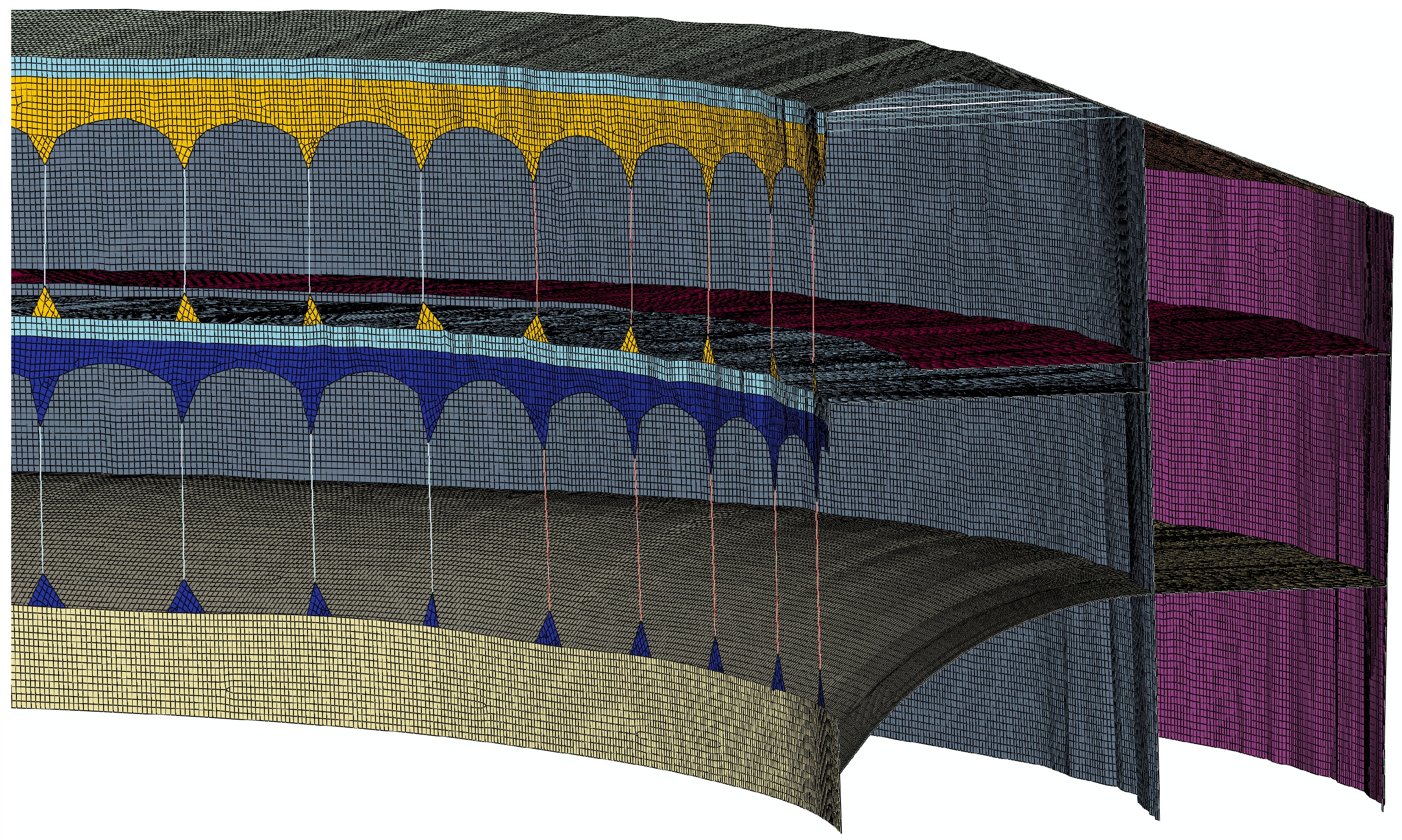
Structural members were modelled with their actual cross-sections, including the volumetric losses recorded in the most deteriorated columns. Walls and arches were represented with shell elements, whereas columns, ties and struts were modelled with beam elements. Tile vaults and floor slabs were simplified as equivalent membranes with homogenised mechanical properties, and the pitched timber roof was reduced to an equivalent-stiffness surface. The final mesh comprised ≈ 1.20 million nodes, 1.21 million elements, and 7.2 million degrees of freedom, providing sufficient resolution to capture existing deformations and stress concentrations in the structure’s most vulnerable zones (
Figure 12).
Boundary conditions assumed full fixity at the foundation level (a simplification to be revisited once detailed geotechnical data become available). Soil–structure interaction was not modelled explicitly. Joints were idealised according to their observed behaviour: pins for ties and struts, and rigid connections between columns and arches. Nine distinct materials were defined to reflect the building’s constructional diversity. Their initial mechanical properties, derived either from sonic-test data (historic masonry) or from standard literature values (concrete, steel and timber), are summarised in
Table 4.
The initial elastic moduli for materials M1–M5 were calculated from the dynamic moduli obtained by sonic testing and converted to static values using Kazi’s empirical relationship [
50]; materials M6–M9 were assigned standard properties and kept constant during the subsequent parameter-updating phase.
5.2. Parametric Model Updating
The model was calibrated by means of a parametric-updating procedure driven by genetic algorithms (GAs), a technique that has proved robust for optimisation problems involving many variables and nonlinear objective functions [
51]. The routine was implemented in MATLAB R2023a [
52], with an automated interface that linked each GA iteration to Abaqus/CAE [
49] for the requisite finite-element analyses.
Five updating variables (M1–M5,
Table 4) were defined, each acting as a multiplicative factor on the initial Young’s modulus of the experimentally identified material groups. This approach refines the elastic moduli while preserving their relative hierarchy. Allowable ranges (±40% of the initial value) were set in accordance with (i) typical uncertainty for historic materials, (ii) values reported in the literature for comparable masonry and (iii) consistency with the sonic-test results.
The objective function minimised the normalised root-mean-square error between numerical and experimental natural frequencies:
using the first five vibration modes, selected for their clear experimental identification and relevance to the global behaviour of the structure.
GA settings were tuned to the present problem: population size = 50, adaptive mutation, and parallel processing on 12 cores to shorten runtimes. Convergence was deemed to occur when no further improvement was observed over 50 generations or when 100 generations were reached, whichever came first.
5.3. Calibration Results
The genetic algorithm optimisation converged after 66 generations, requiring about 96 h of parallel processing. The procedure reduced the global frequency error from 26.2% to 3.24% (
Table 5), thereby confirming the effectiveness of the parametric-updating strategy and the model’s ability to reproduce the experimental dynamic behaviour. The optimal updating factors were 0.80 for the Tier 1 and 4 columns (E = 9.6 GPa), 1.17 for the Tier 2 and 3 columns (E = 17.55 GPa), 1.33 for the stone arcade (E = 3.99 GPa), 0.83 for the brick masonry (E = 0.99 GPa) and 1.07 for the buttresses (E = 1.49 GPa).
The calibrated model reproduces the experimental natural frequencies with errors below 1.5% in every case, and all modal assurance criterion (MAC) values exceed 0.80, indicating excellent agreement in both frequency and mode-shape patterns (
Figure 8). Physical consistency was verified by confirming that the final elastic moduli lie within ranges expected for the historic materials. Moreover, the spatial distribution of stiffness mirrors on-site observations, with lower values in the most deteriorated areas; this correspondence reinforces the credibility of the calibrated model.
The validated model therefore offers a faithful representation of the current dynamic behaviour of the RMR Bullring and provides a reliable basis for the stability analyses and intervention strategies discussed in the following section.
6. Structural-Stability Analysis
This section presents the outcomes of the structural-stability assessment carried out with the calibrated FE model of the RMR Bullring. The analysis had three main goals: (i) to evaluate the current safety conditions of the monument, (ii) to pinpoint those components that demand urgent intervention, and (iii) to elucidate the deformation mechanisms that have produced the observed pathologies.
6.1. Analysis Methodology
The study focused on verifying the ultimate limit state of equilibrium, examining whether the resultant loads remain inside the geometric core of each structural element. This approach is especially appropriate for historic masonry, where working stresses are normally far below the material’s compressive strength and global stability therefore governs structural safety.
For every vertical element (above all, the inner sandstone columns identified as most vulnerable), the load eccentricity was calculated as
where
M is the bending moment and
N is the axial force. The resulting eccentricity was then compared with the core limit of the cross-section, taken as radius/4 for circular sections.
A safety factor was defined as the ratio between the limiting eccentricity and the calculated eccentricity. Values greater than one indicate that the resultant remains within the core and the whole section is in compression. Values below one show that part of the section is in tension, a condition that in masonry may trigger cracking and progressive deterioration, compromising the structural integrity.
To apply the check, each column was discretised into ten segments along its height; axial loads and bending moments were extracted for every segment from the FE model. Two design load cases were considered: the factored self-weight combination and the combination of self-weight plus the design live load corresponding to full occupancy. The design live loads correspond to spectator occupancy loads (5 kN/m
2) as established in the Spanish Structural Code (
CTE DB-SE-AE) [
53], applied with safety factors of 1.35 for permanent loads and 1.5 for variable loads.
6.2. Global Behaviour Analysis
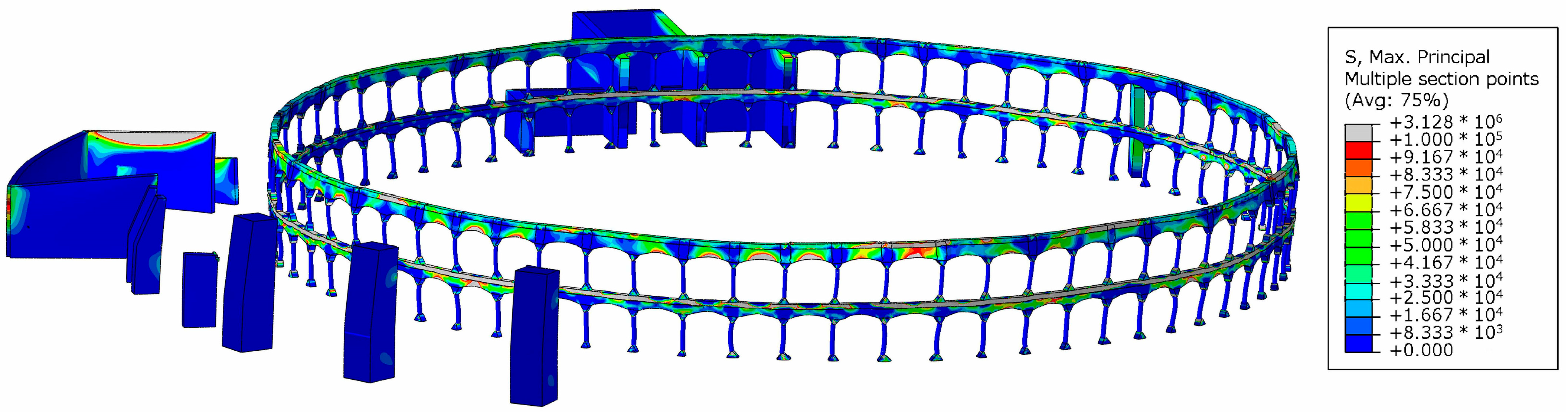
The complete FE model clarifies the overall response of the structure and the deformation mechanisms currently acting on the RMR Bullring. Principal-stress maps highlight significant stress concentrations in discrete parts of the building, particularly beneath the intrados of the arches in Tiers 1 and 2.
Principal tensile stresses reach critical values, above 0.10 MPa, in these arches [
54]. This finding explains the observed pathologies, such as the downward settlement of voussoirs and the insertion of metal shims to recover seating. When the design live load is added, tensile stresses rise by up to 35% in some zones, underlining the structure’s vulnerability to dynamic crowd actions (
Figure 13).
The displacement analysis records maximum vertical movements of 5 mm under factored self-weight, increasing to 7 mm when the live load is included. Although these values are modest, they are critical because they are superimposed on already significant historical deformations and will continue to grow with each loading cycle (
Figure 14).
Global deformation patterns confirm a prevailing tendency towards radial outward movement of the inner arcade, with the largest displacements again concentrated in Tiers 1 and 2. The behaviour is consistent with inadequately counteracted horizontal thrusts that have driven the progressive accumulation of deformation over time
6.3. Column Stability Assessment
The column-by-column stability check forms the core of this section, because the sandstone columns have been identified as the most vulnerable members of the structure.
Lower-storey columns present a generally favourable situation: most safety factors (ratio of core limit eccentricity to calculated eccentricity) exceed 1.50. Two elements, however, approach this threshold (Column 17, Tier 3 (1.59) and Column 12, Tier 1 (1.85)) and should therefore be monitored closely.
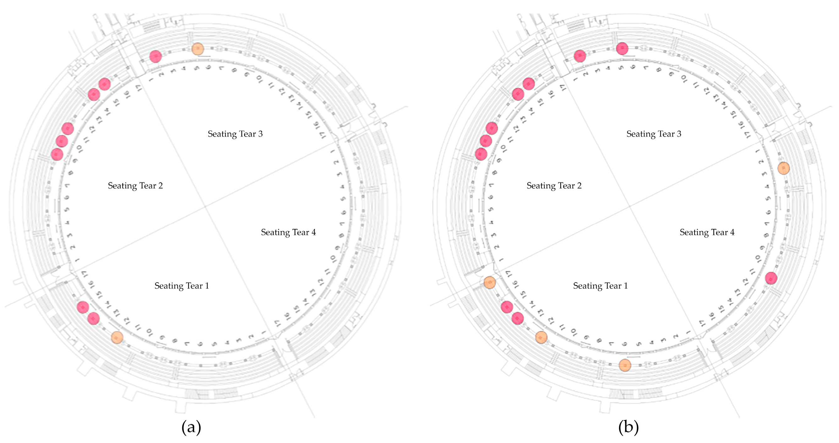
Conditions are markedly more critical at the upper storey. Under factored self-weight alone, 10 columns exhibit safety factors below 1.0, most of them clustered in Tiers 1 and 2. The most severe cases are Columns 11, 14 and 15 of Tier 2, whose minimum factors are 0.64, 0.67 and 0.66, respectively (
Figure 15a). Adding the design live load worsens the outlook significantly: the number of unsafe columns rises to 14, and the minimum factor falls to 0.60. Such values denote a high risk of instability under normal service conditions and raise the possibility of local or progressive collapse if several elements fail simultaneously (
Figure 15b).
The spatial distribution of critical columns is highly non-uniform. They are concentrated in specific zones, particularly the royal box (Tier 2), where the original Lamiable struts were removed during the 1962 restoration without adequate replacement. This correlation between past interventions and current weaknesses provides key insights for understanding damage evolution and for designing effective strengthening measures.
6.4. Effect of Material Degradation on Stability
The integrated analysis of material characterisation data and the stability checks clarifies the influence that stone decay exerts on the structural problems currently affecting the bullring. While areas of pronounced material deterioration do coincide with zones where safety factors are lowest, the evidence shows that material degradation is not the principal cause of the observed deformations; the root lies in structural design deficiencies.
A reduction of about 25% in Young’s modulus in the most weathered zones increases local flexibility and therefore amplifies displacements, but it cannot on its own account for the tilts of up to 0.21 m measured in some upper-tier columns. Numerical simulations demonstrate that, even if homogeneous mechanical properties are assigned to the whole structure, the same critical areas persist, albeit with slightly smaller displacements.
By contrast, cross-section loss due to superficial weathering becomes critical whenever it exceeds 15% of the original column area, because it further reduces the associated safety factors. Nevertheless, the decisive factors remain the columns’ extraordinary slenderness, inherent to the eighteenth-century design, and the insufficient bracing introduced during the 1962 restoration, which fails to provide continuous restraint.
These findings confirm that any successful intervention must tackle both issues: implement global stiffening, particularly in the upper gallery, to counteract horizontal thrusts, and locally restore the most eroded columns to recover their original cross-section.
6.5. Comprehensive Stability Assessment
Integrating the stability analysis findings with the geometric survey and dynamic characterisation data allows a holistic diagnosis of the current condition of the RMR Bullring. The building shows a clear tendency towards imbalance and displays unequivocal symptoms of potential partial, or even global, collapse unless corrective measures are adopted promptly. The evidence supporting this conclusion includes the following:
Safety factors below unity in 10 upper-tier columns under factored self-weight, rising to 14 when the design live load is added.
Cumulative deformations of up to 0.21 m in columns and 0.32 m in perimeter walls, well beyond admissible limits, and still increasing.
Tensile stresses exceed the typical masonry strength in numerous arches and vaults, explaining the cracking observed in these elements.
Natural frequencies in the 3–4 Hz band, coincident with the critical range for public-assembly structures, implying a risk of dynamic amplification under crowd loading.
A poor state of many bracing members, slack tie rods and timber sleepers affected by advanced decay, that undermines the system’s capacity to resist horizontal thrusts.
The root cause of the stability problems lies in the interplay of three main factors: the extraordinary slenderness inherent to the original column design; the inadequate modification of bracing systems during past interventions; and the progressive material decay of the sandstone and ancillary components. An effective solution must therefore adopt an integrated strengthening strategy that restores the global stiffness of the structure, particularly at the upper gallery, through efficient bracing, while simultaneously repairing or replacing the most deteriorated elements.
7. Conclusions
This research has successfully developed and validated a comprehensive multidisciplinary methodology for the structural diagnosis of historic buildings, demonstrated through its application to the 18th-century RMR Bullring. The study’s primary contribution lies in demonstrating how the integration of complementary non-destructive experimental techniques can significantly enhance the reliability of heritage structural assessment, transforming the traditional approach from isolated inspections to holistic understanding.
The integration of advanced 3D laser-scanning technology with complementary dynamic characterisation techniques (ST, OMA and EMA) has proven exceptionally effective in reducing the inherent uncertainties that compromise structural analysis in architectural heritage. Each technique contributed specific information that, when combined, provided comprehensive insights significantly beyond what individual methods could deliver independently. The 3D laser scanning established the precise geometric foundation, capturing over 1 billion points with millimetric accuracy to document accumulated deformations that conventional surveys would miss. This geometric fidelity became crucial for developing an FE model that could accurately represent the current deformed state rather than a theoretical geometric survey. The automated processing routines developed enabled efficient extraction of structural geometry from massive point clouds, providing the essential foundation for all subsequent analyses. The systematic application of ST emerged as particularly valuable, enabling the non-destructive mapping of elastic moduli variations throughout the building and revealing spatial patterns of material degradation that correlate directly with observed pathologies. When combined with OMA for global dynamic characterisation and EMA for local assessment of critical elements, this integrated approach successfully identified latent structural vulnerabilities that would have remained undetected.
The development and calibration of numerical models formed an important synthesis step, integrating all experimental data into an FE model. The parametric-updating procedure achieved remarkable accuracy, reducing the global frequency error from 26.2% to 3.24% and demonstrating the model’s capacity to faithfully reproduce the experimental dynamic behaviour. This calibrated model not only serves as a reliable tool for current stability assessment but also establishes a validated baseline for future monitoring and intervention planning. The strong correlation between numerical predictions and experimental observations, evidenced by modal assurance criterion values exceeding 0.80 for all identified modes, confirms the model’s reliability and its suitability for structural analysis.
The stability analysis reveals an alarming structural condition that demands immediate attention. The identification of fourteen upper-gallery columns operating with safety factors below 1 under normal service conditions, escalating to nineteen columns when full-occupancy loads are considered, represents a critical safety concern. The research establishes that these vulnerabilities stem primarily from the extraordinary slenderness inherent to the original eighteenth-century design philosophy, compounded by inadequate horizontal bracing systems resulting from incomplete historical interventions. The removal of Lamiable’s nineteenth-century struts during the 1962 restoration, without systematic replacement throughout the entire structure, has left numerous columns without essential lateral restraint, allowing uncontrolled horizontal thrusts from the shallow arches to drive progressive radial displacements. While material degradation contributes to the overall deterioration, with sonic testing revealing modulus reductions of up to 25% in the most exposed areas, the analysis demonstrates that structural deficiencies rather than material decay constitute the primary cause of the observed instability. Moreover, the fact that the structure’s fundamental vibration modes lie within the 3–4 Hz frequency band according to OMA results, identified by Spanish building codes as critical for spectator venues, introduces an additional layer of concern regarding dynamic amplification under crowd loading. These, combined with the documented static vulnerabilities, suggest that the building faces both instability risks and potential dynamic amplification effects that could accelerate the deterioration process. Based on these findings, this research recommends the implementation of a comprehensive strengthening strategy that addresses both global structural deficiencies and local material deterioration.
The methodology presented in this study transcends the specific case of the RMRBullring, offering practitioners a scientifically rigorous and evidence-based approach to the diagnosis of heritage structures. The systematic integration of geometric documentation, dynamic characterisation, and numerical modelling provides a replicable framework that can be adapted to a wide range of historic buildings while maintaining the precision and reliability required for critical safety assessments. However, this study presents certain inherent limitations that should be acknowledged. The methodology involves constraints typical of heritage structural assessment, including assumptions regarding material homogeneity and boundary conditions. The material characterisation approach, while sufficient for the study objectives, is limited by the scope of non-destructive testing techniques employed and the spatial heterogeneity inherent in historic masonry. Additionally, the assessment is based on a single case study, and broader validation across different heritage typologies would strengthen the methodology’s general applicability.
Future research directions should focus on refining in situ wave propagation methodologies for enhanced material characterisation, developing advanced algorithms for automated structural anomaly detection, and exploring innovative minimally invasive reinforcement strategies that preserve historic building integrity. Additionally, investigations should consider soil-structure interaction effects on natural frequencies and base restraint assumptions. The continuation of this work involves designing structural strengthening and retrofitting strategies for the identified critical elements, particularly columns and bracing systems, utilising the accurately calibrated finite-element model. The continued advancement of these methodologies will be essential for ensuring the preservation of our cultural heritage.
Author Contributions
Conceptualization, P.P. and V.C.; methodology, P.P. and C.G.; software, P.P. and E.V.-V.; validation, P.P., C.G., and V.C.; formal analysis, P.P. and C.G.; investigation, P.P. and C.G.; resources, E.V.-V., J.R.B., and V.C.; data curation, P.P.; writing—original draft preparation, P.P.; writing—review and editing, P.P., C.G., E.V.-V., J.R.B., and V.C.; visualization, P.P. and C.G.; supervision, E.V.-V., J.R.B., and V.C.; project administration, E.V.-V. and V.C.; funding acquisition, E.V.-V. All authors have read and agreed to the published version of the manuscript.
Funding
This research received no external funding.
Data Availability Statement
The data are available on request.
Acknowledgments
The authors would like to thank the Real Maestranza de Caballería de Ronda and Bozzo Arquitectos S.L.P. for granting access to the building and for supplying the historical documentation that made this study possible. This research was supported by the research contract “PRJ202304720” (Contract 68/83: Structural Stability Assessment of the Bullring of Ronda, Principal Researcher: Enrique Vázquez Vicente).
Conflicts of Interest
The authors declare no conflicts of interest.
References
- Ramos, L.F.; Aguilar, R.; Lourenço, P.B.; Moreira, S. Dynamic Structural Health Monitoring of Saint Torcato Church. Mech. Syst. Signal Process. 2013, 35, 1–15. [Google Scholar] [CrossRef]
- Gentile, C.; Saisi, A. Ambient vibration testing of historic masonry towers for structural identification and damage assessment. Constr. Build. Mater. 2007, 21, 1311–1321. [Google Scholar] [CrossRef]
- Lourenço, P.B. Computations on historic masonry structures. Prog. Struct. Eng. Mater. 2002, 4, 301–319. [Google Scholar] [CrossRef]
- Betti, M.; Vignoli, A. Numerical assessment of the static and seismic behaviour of the basilica of Santa Maria all’Impruneta (Italy). Constr. Build. Mater. 2008, 25, 4308–4324. [Google Scholar] [CrossRef]
- Ramos, L.F. Damage Identification on Masonry Structures Based on Vibration Signatures. Ph.D. Thesis, University of Minho, Braga, Portugal, 2007. [Google Scholar]
- Jiang, C.; Hu, W.; Zhang, G. Research on Fine Model Reconstruction Method of Ancient Architecture Based on Least Squares Method. npj Herit. Sci. 2025, 13, 95. [Google Scholar] [CrossRef]
- Rainieri, C.; Fabbrocino, G. Operational Modal Analysis of Civil Engineering Structures; Springer: New York, NY, USA, 2014. [Google Scholar]
- Marciniak, P.; Pawlak, Z.M.; Wyczałek, I. The Use of Experimental Modal Analysis in Modeling the Complex Timber Structure of a Historical Building. Appl. Sci. 2024, 14, 8517. [Google Scholar] [CrossRef]
- Uncu, G.; Dede, S.; Çaktı, E. Mechanical properties evaluation of Blue Mosque minaret stones: An experimental campaign. In Proceedings of the 18th World Conference on Earthquake Engineering (WCEE 2024), Milan, Italy, 30 June–5 July 2024; International Association of Earthquake Engineering: Tokyo, Japan, 2024. [Google Scholar]
- Masciotta, M.G.; Roque, J.C.; Ramos, L.F.; Lourenço, P.B. A multidisciplinary approach to assess the health state of heritage structures: The case study of the Church of Monastery of Jerónimos in Lisbon. Constr. Build. Mater. 2016, 116, 169–187. [Google Scholar] [CrossRef]
- Friswell, M.I.; Mottershead, J.E. Finite Element Model Updating in Structural Dynamics; Springer Science & Business Media: Berlin, Germany, 1995. [Google Scholar]
- Providakis, C.P.; Mousteraki, M.G.; Providaki, G.C. Operational modal analysis of historical buildings and finite-element model updating using a laser-scanning vibrometer. Infrastructures 2023, 8, 37. [Google Scholar] [CrossRef]
- Amer, O.; Aita, D.; Bompa, D.V.; Mohamed, E.K.; Hussein, Y.M.; Torky, A.; Mansour, M.M.A. Conservation-oriented integrated approach for structural stability assessment of complex historic masonry structures. J. Eng. Res. 2024, 13, 1551–1593. [Google Scholar] [CrossRef]
- Grămescu, A.M.; Isopescu, D.N.; Carazeanu Popovici, I.; Pericleanu, M.; Pericleanu, B.D.; Anghelescu, C.E.; Voicu, G.; Ghiga, D.A. Material and structural characterization of historical masonry: Analytical framework for restoration planning. Appl. Sci. 2025, 15, 6176. [Google Scholar] [CrossRef]
- Zucca, M.; Reccia, E.; Vecchi, E.; Pintus, V.; Dessì, A.; Cazzani, A. An Evaluation of the Structural Behaviour of Historic Buildings Under Seismic Action: A Multidisciplinary Approach Using Two Case Studies. Appl. Sci. 2024, 14, 10274. [Google Scholar] [CrossRef]
- Saisi, A.; Borlenghi, P.; Gentile, C. Between Safety and Conservation—Procedure for the Assessment of Heritage Buildings Based on Historic Research. Buildings 2023, 13, 2236. [Google Scholar] [CrossRef]
- Vorsevi, S.A. Estudio de Alteraciones de la Roca; Plaza de Toros de Ronda: Ronda, Spain, 2022. [Google Scholar]
- Binda, L.; Saisi, A.; Tiraboschi, C. Investigation procedures for the diagnosis of historic masonries. Constr. Build. Mater. 2000, 14, 199–233. [Google Scholar] [CrossRef]
- Yang, X.; Grussenmeyer, P.; Koehl, M.; Macher, H.; Murtiyoso, A.; Landes, T. Review of built heritage modelling: Integration of HBIM and other information techniques. J. Cult. Herit. 2020, 46, 350–360. [Google Scholar] [CrossRef]
- López, F.J.; Lerones, P.M.; Llamas, J.; Gómez-García-Bermejo, J.; Zalama, E. A review of heritage building information modeling (H-BIM). Multimodal Technol. Interact. 2018, 2, 21. [Google Scholar] [CrossRef]
- Stylianidis, E.; Remondino, F. 3D Recording, Documentation and Management of Cultural Heritage; Whittles Publishing: Scotland, UK, 2016. [Google Scholar]
- Barazzetti, L.; Banfi, F.; Brumana, R.; Gusmeroli, G.; Previtali, M.; Schiantarelli, G. Cloud-to-BIM-to-FEM: Structural simulation with accurate historic BIM from laser scans. Simul. Model. Pract. Theory 2017, 57, 71–87. [Google Scholar] [CrossRef]
- Brincker, R.; Zhang, L.; Andersen, P. Modal identification from ambient responses using frequency domain decomposition. In Proceedings of the 18th International Modal Analysis Conference (IMAC), San Antonio, TX, USA, 7–10 February 2000; pp. 625–630. [Google Scholar]
- Reynders, E.; Houbrechts, J.; De Roeck, G. Fully automated (operational) modal analysis. Mech. Syst. Signal Process. 2012, 29, 228–250. [Google Scholar] [CrossRef]
- Brincker, R.; Ventura, C.; Andersen, P. Damping estimation by frequency domain decomposition. In Proceedings of the 19th International Modal Analysis Conference (IMAC), Orlando, FL, USA, 5–8 February 2001; pp. 698–703. [Google Scholar]
- Peeters, B.; De Roeck, G. Stochastic system identification for operational modal analysis: A review. J. Dyn. Syst. Meas. Control. 2001, 123, 659–667. [Google Scholar] [CrossRef]
- Van Overschee, P.; De Moor, B. Subspace Identification for Linear Systems: Theory-Implementation-Applications; Kluwer Academic Publishers: Dordrecht, The Netherlands, 1996. [Google Scholar]
- Fan, W.; Qiao, P. Vibration-based damage identification methods: A review and comparative study. Struct. Health Monit. 2011, 10, 83–111. [Google Scholar] [CrossRef]
- Grazzini, A. Sonic and Impact Test for Structural Assessment of Historical Masonry. Appl. Sci. 2019, 9, 5148. [Google Scholar] [CrossRef]
- Miranda, L.; Cantini, L.; Guedes, J.; Binda, L.; Costa, A. Applications of sonic tests to masonry elements: Influence of joints on the propagation velocity of elastic waves. J. Mater. Civ. Eng. 2013, 25, 184–192. [Google Scholar] [CrossRef]
- Atamturktur, S.; Laman, J.A. Finite element model correlation and calibration of historic masonry monuments: Review. Struct. Des. Tall Spec. Build. 2010, 21, 96–113. [Google Scholar] [CrossRef]
- Lacanna, G.; Betti, M.; Ripepe, M.; Bartoli, G. Dynamic Identification as a Tool to Constrain Numerical Models for Structural Analysis of Historical Buildings. Front. Built Environ. 2020, 6, 40. [Google Scholar] [CrossRef]
- Salachoris, G.P.; Standoli, G.; Betti, M. Evolutionary numerical model for cultural heritage structures via genetic algorithms: A case study in central Italy. Bull. Earthq. Eng. 2024, 22, 3591–3625. [Google Scholar] [CrossRef]
- Como, M. Statics of Historic Masonry Constructions; Springer: Berlin/Heidelberg, Germany, 2013. [Google Scholar]
- Heyman, J. The Stone Skeleton: Structural Engineering of Masonry Architecture; Cambridge University Press: Cambridge, UK, 1995. [Google Scholar]
- Allemang, R.J.; Brown, D.L. A correlation coefficient for modal vector analysis. In Proceedings of the 1st International Modal Analysis Conference (IMAC), Orlando, FL, USA, 8–10 November 1982; pp. 110–116. [Google Scholar]
- Pastor, M.; Binda, M.; Harčarik, T. Modal assurance criterion. Procedia Eng. 2012, 48, 543–548. [Google Scholar] [CrossRef]
- de Andalucía, J. DECRETO 179/1993, de 30 de Noviembre, Por el Que se Declara Bien de Interés Cultural, con la Categoría de Monumento, la Plaza de Toros de Ronda (Málaga); Boletín Oficial de la Junta de Andalucía (BOJA): Sevilla, España, 1993. [Google Scholar]
- López Collado, G. Técnicas de Ordenación de Conjuntos Histórico-Artísticos y Obras Características; Ministerio de Obras Públicas y Urbanismo: Madrid, Spain, 1982. [Google Scholar]
- Benjumea, J.M. Proyecto de Obras de Reconstrucción y Consolidación en la Plaza de Toros de Ronda; Dirección General de Arquitectura: Madrid, Spain, 1947. [Google Scholar]
- Pons Sorolla, F.; Moya Blanco, R. Proyecto de Restauración de la Plaza de Toros de Ronda; Dirección General de Arquitectura: Madrid, Spain, 1962. [Google Scholar]
- Vázquez, E.; Compán, V. Informe de Estabilidad de Elementos Estructurales de la Plaza de Toros de Ronda; Universidad de Sevilla: Sevilla, Spain, 2024. [Google Scholar]
- Vorsevi, S.A. Estudio Geotécnico para Análisis de Patología de la Plaza de Toros de Ronda; Technical Report No 500147Rev0; Vorsevi, S.A.: Seville, Spain, 2024. [Google Scholar]
- Kang, Z.; Li, J.; Zhang, L.; Zhao, Q.; Zlatanova, S. Automatic registration of terrestrial laser scanning point clouds using panoramic reflectance images. Sensors 2009, 9, 2621–2646. [Google Scholar] [CrossRef] [PubMed]
- McNeel, R. Rhinoceros 3D: A Comprehensive Guide; McNeel & Associates: Seattle, DC, USA, 2023. [Google Scholar]
- McNeel, R. Grasshopper; Versión 2.0 alpha; McNeel & Associates: Seattle, DC, USA, 2024. [Google Scholar]
- Structural Vibration Solutions A/S. ARTeMIS Modal Pro; Versión 8.0; Structural Vibration Solutions A/S: Aalborg, Denmark, 2024. [Google Scholar]
- Ministerio de Transportes, Movilidad y Agenda Urbana. Código Técnico de la Edificación. Documento Básico SE-AE: Acciones en la Edificación; Gobierno de España: Madrid, Spain, 2024. [Google Scholar]
- Dassault Systèmes. Abaqus/CAE; Versión 2024; Dassault Systèmes: Vélizy-Villacoublay, France, 2024. [Google Scholar]
- Eissa, E.A.; Kazi, A. Relationship between static and dynamic Young’s moduli of rocks. Int. J. Rock Mech. Min. Sci. Geomech. Abstr. 1988, 25, 479–482. [Google Scholar] [CrossRef]
- Marwala, T. Finite-Element-Model Updating Using Genetic Algorithm. En Finite-Element-Model Updating Using Computational Intelligence Techniques; Springer: Berlin/Heidelberg, Germany, 2010; pp. 49–66. [Google Scholar] [CrossRef]
- The MathWorks, Inc. MATLAB; Versión 9.14.0 [R2023a]; The MathWorks: Natick, MA, USA, 2023. [Google Scholar]
- Ministerio de Transportes, Movilidad y Agenda Urbana. Código Técnico de la Edificación. Documento Básico SE: Seguridad Estructural; Gobierno de España: Madrid, Spain, 2024. [Google Scholar]
- Tomaževič, M. Shear resistance of masonry walls and Eurocode 6: Shear versus tensile strength of masonry. Mater. Struct. 2009, 42, 889–907. [Google Scholar] [CrossRef]
Figure 1.
Integrated methodology for the structural diagnosis of historic buildings.
Figure 1.
Integrated methodology for the structural diagnosis of historic buildings.
Figure 2.
RMR Bullring (Málaga, Spain).
Figure 2.
RMR Bullring (Málaga, Spain).
Figure 3.
Floor plan (a) and section (b) of the RMR Bullring (Málaga, Spain).
Figure 3.
Floor plan (a) and section (b) of the RMR Bullring (Málaga, Spain).
Figure 4.
Deformations in stall columns, and arches showing cracking and section loss.
Figure 4.
Deformations in stall columns, and arches showing cracking and section loss.
Figure 5.
Point cloud obtained after laser scanning of the RMR Bullring.
Figure 5.
Point cloud obtained after laser scanning of the RMR Bullring.
Figure 6.
Displacements between the initial and final points of the grandstand columns. The local deformation at each storey and the total deformation are shown. Units (m).
Figure 6.
Displacements between the initial and final points of the grandstand columns. The local deformation at each storey and the total deformation are shown. Units (m).
Figure 7.
Example of a column section generated by the Grasshopper routine.
Figure 7.
Example of a column section generated by the Grasshopper routine.
Figure 10.
EMA set-up and mode shapes identification.
Figure 10.
EMA set-up and mode shapes identification.
Figure 11.
FE model of the RMR Bullring.
Figure 11.
FE model of the RMR Bullring.
Figure 12.
FE model showing the deformation included in the structural model.
Figure 12.
FE model showing the deformation included in the structural model.
Figure 13.
Principal Tensile Stress. Permanent Load + Live Load Combination. Zones with stresses greater than 0.10 MPa are shown in grey.
Figure 13.
Principal Tensile Stress. Permanent Load + Live Load Combination. Zones with stresses greater than 0.10 MPa are shown in grey.
Figure 14.
Displacement map. Permanent Load + Live Load Combination. The colour scale ranges from blue (0 mm) to red (5 mm).
Figure 14.
Displacement map. Permanent Load + Live Load Combination. The colour scale ranges from blue (0 mm) to red (5 mm).
Figure 15.
Upper-storey columns with low safety factors. Permanent-load combination (a) and permanent plus factored live-load combination (b). Columns with safety factors between 0.85 and 1.0 are shown in yellow; those below 0.85 are shown in red.
Figure 15.
Upper-storey columns with low safety factors. Permanent-load combination (a) and permanent plus factored live-load combination (b). Columns with safety factors between 0.85 and 1.0 are shown in yellow; those below 0.85 are shown in red.
Table 1.
Natural frequencies identified by OMA.
Table 1.
Natural frequencies identified by OMA.
| Mode | EFDD (Hz) | SSI UPCX (Hz) | Δf (%) | MAC |
|---|
| 1 | 4.135 | 4.148 | 0.31 | 0.90 |
| 2 | 4.493 | 4.484 | 0.20 | 0.81 |
| 3 | 4.736 | 4.769 | 0.69 | 0.88 |
| 4 | 5.279 | 5.275 | 0.07 | 0.83 |
| 5 | 5.639 | 5.618 | 0.37 | 0.87 |
Table 2.
Mechanical parameters of the columns—mean values per tier.
Table 2.
Mechanical parameters of the columns—mean values per tier.
| Tier | Vp (m/s) | Vs (m/s) | ρ (kg/m3) | ν | Gdyn (GPa) | Edyn (GPa) |
|---|
| T1 | 3149.42 | 1827.18 | 2040.00 | 0.255 | 6.81 | 16.84 |
| T2 | 3544.23 | 2056.92 | 2040.00 | 0.248 | 8.62 | 22.29 |
| T3 | 3512.05 | 2033.76 | 2040.00 | 0.265 | 8.41 | 20.84 |
| T4 | 3279.76 | 1902.12 | 2040.00 | 0.247 | 7.40 | 18.10 |
Table 3.
Experimental natural frequencies (Hz).
Table 3.
Experimental natural frequencies (Hz).
| Mode | Column 2 | Column 13 | Column 15 |
|---|
| 1 | 71.9 | 75.9 | 40.6 |
| 2 | 167.7 | 167.85 | 137.0 |
| 3 | 292.5 | 307.82 | 260.1 |
| 4 | 426.7 | 486.09 | 350.3 |
Table 4.
Initial mechanical properties of the materials used in the model.
Table 4.
Initial mechanical properties of the materials used in the model.
| Material | Description | Density (kg/m3) | Eest (GPa) | Poisson’s Ratio |
|---|
| M1 | Stone, Tiers 1–4 | 2040 | 12.00 | 0.25 |
| M2 | Stone, Tiers 2–3 | 2040 | 15.00 | 0.25 |
| M3 | Stone masonry | 1950 | 3.00 | 0.25 |
| M4 | Brick masonry | 1900 | 1.20 | 0.20 |
| M5 | Buttress masonry | 1900 | 1.40 | 0.20 |
| M6 | Concrete | 2500 | 20.00 | 0.30 |
| M7 | Steel | 7850 | 200.00 | 0.20 |
| M8 | Tie-Rod steel | 7850 | 200.00 | 0.20 |
| M9 | Timber | 800 | 0.70 | 0.20 |
Table 5.
Updating results. Experimental natural frequency, fexp, initial numerical natural frequency, fini, updated numerical natural frequency fupd, relative differences, Δf, and the MAC ratio.
Table 5.
Updating results. Experimental natural frequency, fexp, initial numerical natural frequency, fini, updated numerical natural frequency fupd, relative differences, Δf, and the MAC ratio.
| Mode | fexp (Hz) | fini (Hz) | Δf fexp-fupd (%) | fupd (Hz) | Δf fexp-fupd (%) | MAC exp-upd |
|---|
| 1 | 4.135 | 4.370 | 5.378 | 4.145 | 0.241 | 0.95 |
| 2 | 4.493 | 4.801 | 6.415 | 4.558 | 1.426 | 0.83 |
| 3 | 4.736 | 4.991 | 5.109 | 4.728 | 0.169 | 0.85 |
| 4 | 5.279 | 5.494 | 3.913 | 5.213 | 1.266 | 0.87 |
| 5 | 5.639 | 5.960 | 5.386 | 5.631 | 0.142 | 0.88 |
| Disclaimer/Publisher’s Note: The statements, opinions and data contained in all publications are solely those of the individual author(s) and contributor(s) and not of MDPI and/or the editor(s). MDPI and/or the editor(s) disclaim responsibility for any injury to people or property resulting from any ideas, methods, instructions or products referred to in the content. |
© 2025 by the authors. Licensee MDPI, Basel, Switzerland. This article is an open access article distributed under the terms and conditions of the Creative Commons Attribution (CC BY) license (https://creativecommons.org/licenses/by/4.0/).


 ,
, 


