1. Introduction
The technical imaging of glass surfaces presents many challenges; for instance, light may reflect through transparent glass walls or bounce on cold-worked and/or damaged surface features, obscuring the recording of fine details. This paper presents a technical note on adapting Reflectance Transformation Imaging (RTI) using both white and blue light to capture fine surface details on glass, focusing in particular on crizzled glass surfaces. We also discuss methods for tracking changing surfaces through image subtraction using Adobe Photoshop.
Our interest arose during preparation for a Smithsonian Institution-wide project, the Glass Deterioration Working Group (GDWG), which focused on the assessment of glass condition across the museums, with a particular interest in unstable glass. The group has reviewed published accounts of such glass compositions and will be sharing the Smithsonian-wide results in future articles [
1]. The phenomenon, sometimes referred to as glass disease, occurs when atmospheric moisture leaches alkali and alkaline ions and replaces them with hydrogen atoms in the glass network. This destabilization proceeds when the original glass melt is improperly batched, and the composition does not include sufficient components to stabilize the glass network, such as calcium oxide. The resulting surface is often referred to as silica-enriched. Depending on the relative humidity, alkaline salts may deliquesce atop the object so the glass appears to be “weeping”, or if drier, a network of fine cracks called crizzling appears following the dehydration of that surface layer [
2,
3,
4,
5,
6]. Work for the GDWG led to a review of decorative objects with visible instability, including several glass-fronted buttons. We investigated the best techniques to document them, given the small size of these objects as well as the fine details of the crizzled surface.
RTI is a useful tool for studying surface details of objects and, as such, has been used widely within art conservation to reveal features not otherwise apparent or readily visible [
7,
8,
9]. These studies have used RTI to explore toolmarks [
9], painted lines [
10], engravings [
11], the physical evidence of the making process [
12], and condition and degradation features (scratches, inclusions, corrosion, cracks, and craquelure) [
7,
11]. Techniques have included highlight-based RTI and dome-based RTI at a range of scales including micro-RTI [
7,
11]. While most discussions of the technique examine opaque media, some published studies to date do focus on adapting the technique to capture glass and/or transparent objects [
11,
12,
13].
Previous studies have investigated RTI using wavelengths beyond visible light, including IR-RTI of painted surfaces to investigate the painting process and hidden features [
14] and to read blackened papyri [
15] and UV-based RTI with both UV-induced visible luminescence (UVL) and reflected UV (RUV) of a painted and incised ceramic vessel to document surface variations and previous repairs [
16]. Hameeuw [
17] presented the use of different wavelengths to improve the recording of objects that are optically challenging due to material, color, glossiness, translucency, or transparency, specifically focusing on stone seals and metal coins. While Hameeuw is not using RTI but a related multi-light technique, his findings can inform the wavelength selection for using RTI to record glass surfaces. White light (or visible light) is useful for providing a good visual color representation for glossy, translucent, and transparent stone objects, but for the accurate recording of the surface shape, it is recommended to record blue or UV bands to exclude longer wavelengths that reflect in a more complex manner.
This work investigates the potential of both white light and blue light RTI using a dome-based setup to record the degradation of glass surfaces that are otherwise difficult to record and monitor. Comparison of the resulting images and RTI files allowed the assessment of the usefulness of the technique as a tool to track changes over time.
2. Materials and Methods
2.1. Mock-Up and Case Study
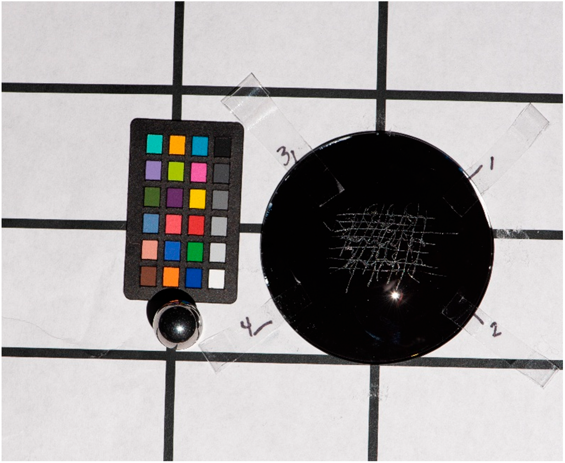
To replicate fine surface details such as the web of fine cracks present on three-dimensional unstable glass or cold-worked tool marks such as wheel-cut designs, we created a mock-up to represent collection pieces using a watch glass and a diamond scribe. Following experimentation with various methods of reducing undesirable light reflection from the back wall of the vessel to the surface area of interest, which complicated the legibility of the final images, we settled on painting the concave side of the glass with black gouache. This step increased the opacity of the glass, which then reduced the amount of light available to bounce back through the transparent medium. (This preparation can be safely adapted for unstable collection objects by placing black paper in close contact with the underside of glass pieces, or by casting out a thin layer of silicone rubber that has been dyed black. Once set, the rubber layer can be rolled onto the reverse of the glass piece. In this way, the use of gouache may be avoided.)
Next, we incised a loose pattern on top of the convex surface of the glass and proceeded with imaging (details below, “Image Set 1”). Then we added additional marks to the surface to suggest progressive changes in topography, such as a glass that continues to crizzle in new areas (“Image Set 2”). Following this step, we took a second set of images using the RTI dome. The watch glass was placed on a gridded piece of paper to assist in the consistent positioning of the object in relation to the dome and camera to facilitate monitoring over time and set-up repeatability (
Figure 1).
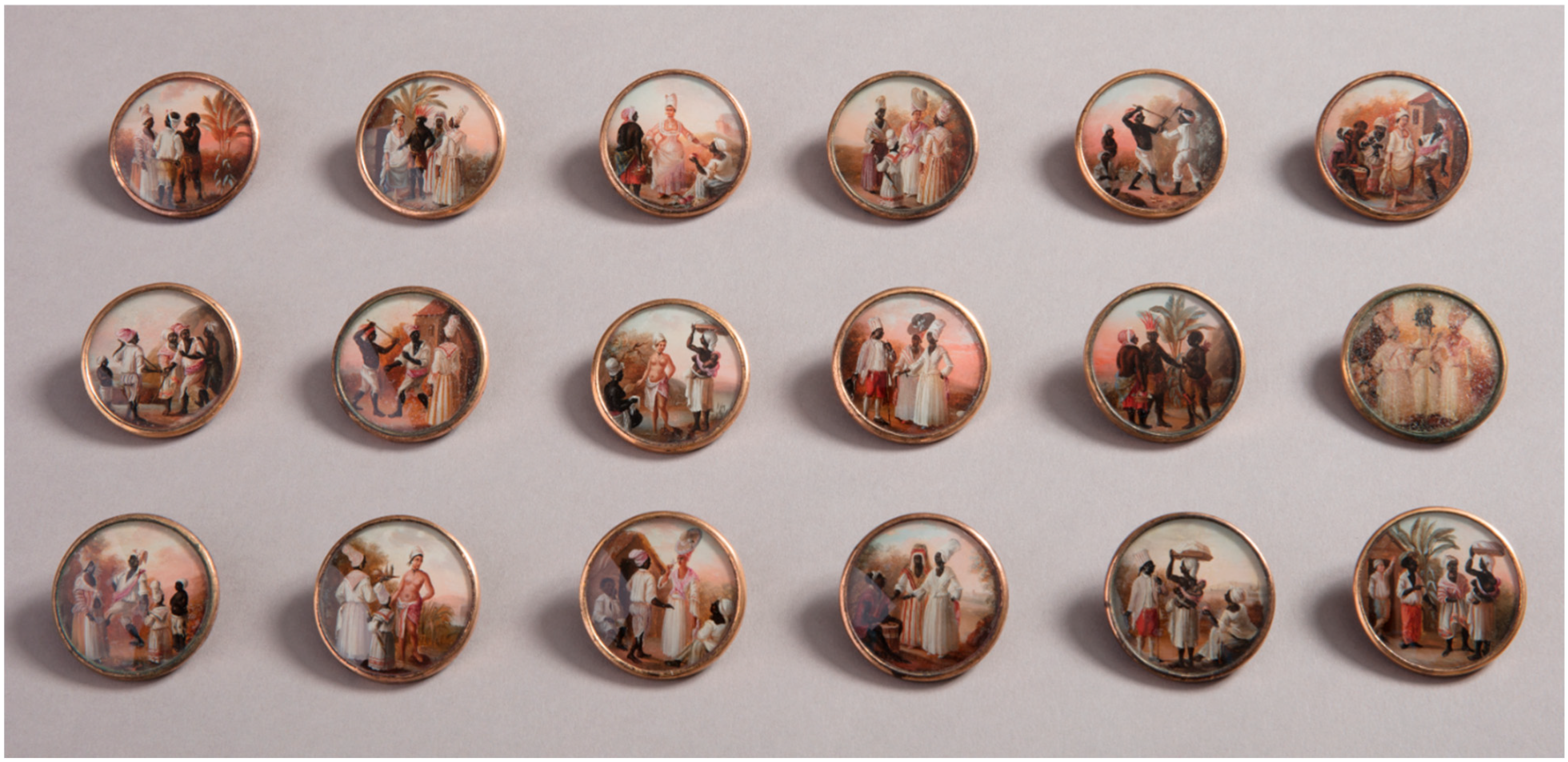
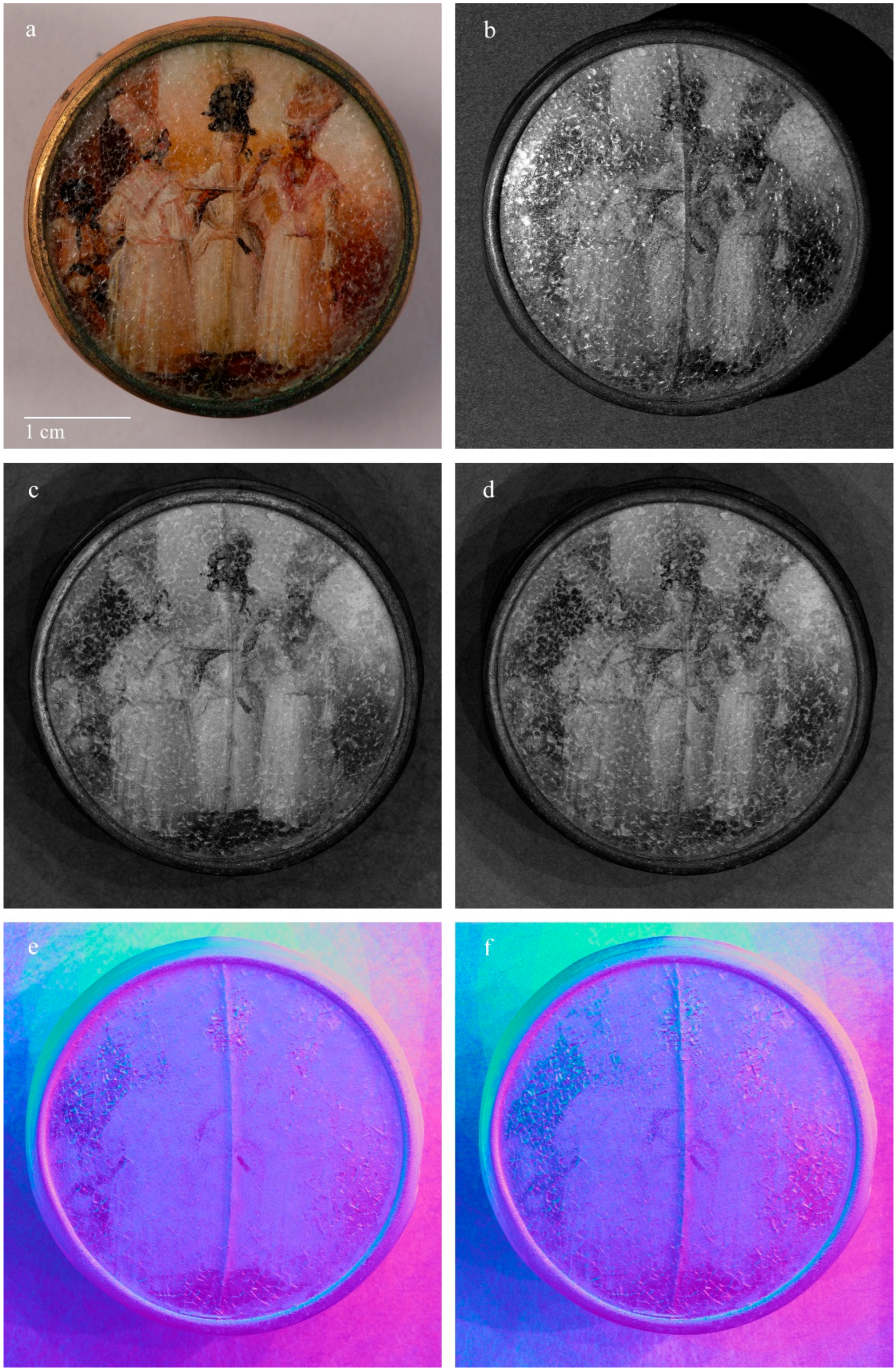
Concurrently, we used the RTI dome to capture a suite of images of a crizzled glass-fronted button from the museum’s collection. The button, 1949-94-10, is part of a series of 18 buttons with ivory miniatures featuring various figural scenes set in a tropical setting (
Figure 2). The whole suite has been attributed to Agostino Brunias (Italian, ca. 1730–1796) and was possibly owned by Haitian Independence leader Toussaint L’Overture. The buttons have been requested for loan by multiple institutions. These requests have been granted with the exception of two buttons that exhibit unstable glass, raising concerns over potential damage incurred during transport. These buttons continue to be stored in the Conservation Laboratory to allow for ongoing condition checks and study.
2.2. Photography and RTI Dome
The photography (both standard documentation and RTI) used a full-spectrum UV-VIS-IR modified Nikon D750 camera (25MP CMOS sensor) (Tokyo, Japan) with a Nikon 105 mm macro lens. The camera was modified by LifePixel (Mukilteo, Washington, DC, USA) by removing the internal hot mirror filter. A HOYA UV-IR cut filter was used on the lens. An X-Rite Nano ColorChecker was used for setting the exposure and color correction for standard photography and RTI. The RTI image sets included a reflective sphere with a 1 cm diameter to enable the highlight-based calculations of light positions.
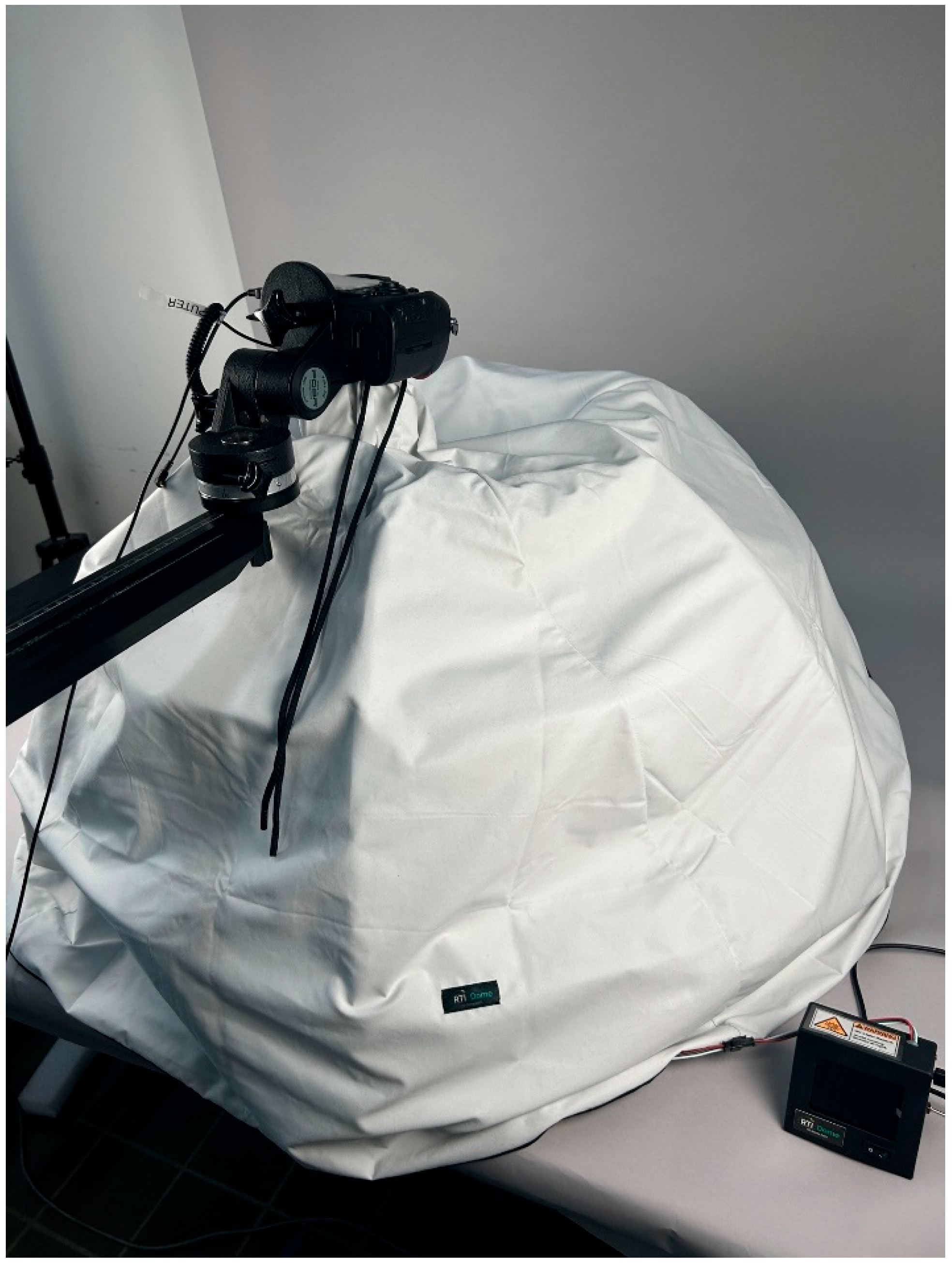
The RTI dome was designed and built by FlyDome SAS (Paris, France). The dome holds 54 LED light disks arranged across three metal rings that snap together with a base diameter of 90 cm. Each disk contains four diodes: white light (5500–6500 K CCT); blue light (440–460 nm); UV (365–370 nm); IR (825–830 nm). A cloth drape folds over the structure to block ambient light (
Figure 3). In order to ensure that the lowest rung of lights adequately illuminated both the mock-up and the button, the feet of the dome were raised about six inches, and an additional cloth was draped to block ambient light.
The entire system runs via a control box, which connects to the camera situated atop the dome. The user can choose which diode and the length of the light exposure time through the control box. Certain exposure conditions require extended times for acceptable images; for instance, blue light images routinely require 10–15 s shutter exposures, given the low illumination generated.
The mock-up and the crizzled button were photographed as a 54-image RTI set under both white light and blue light, respectively (“Image Set 1” for mock-up). The mock-up was photographed a second time under the same conditions following additional scribing (“Image Set 2”).
Images were processed using Adobe Bridge to update metadata and Adobe Camera Raw to desaturate images and export JPEGs for RTI processing. All RTI images were desaturated (both visible and blue light) to remove color information following recommendations from [
18]. RGB levels were measured in Camera Raw following the desaturation of the white balanced test images, and an attempt was made to unify these levels across image sets.
2.3. RTI Processing and Visualization
The RTI files were processed using ReLight Lab 2024.11 (Visual Computing Lab, Institute of Information Science and Technologies, Italian National Research Council, Pisa, Italy), using the HSH RGB algorithm. While the composite RTI file initially looks like a 2D photograph, it includes the documentation of the object’s surface interaction with the varying light positions at the individual pixel level, offering dynamic relighting and select data enhancement options. The final RTI file is viewed in a specialized viewer, like the RTIViewer, and by moving the mouse, the viewer can control the light direction, zoom in and out, and select different visualization options [
19]. The different visualization options in RTIViewer are mathematical transformations based on surface shape and color to enhance the visibility of some features and provide more information about the surface than a standard visible light image. The default view does not include any mathematical enhancements. The specular enhancement mode increases or decreases the specularity of the object and removes the color, which can help to enhance the perception of the shape of some materials and surfaces. The normals visualization mode provides a false-color rendering representing the object’s surface orientation, which can help with investigating the surface contours.
2.4. Post-RTI Processing
Additional image processing, like image subtraction, can be helpful in showing the difference between images and visualizing changes over time. Image subtraction is an image processing technique where one image is subtracted from another (at the pixel level), resulting in a new image that shows the difference between the two initial images. This technique has been used in conservation applications with multiband imaging to map specific materials like indigo [
18]. The images used for the processing can either be input images for the RTI or exported views from RTIViewer. Image subtraction was performed using Photoshop with the two images included as separate layers in the same image file and using the “Difference” blending mode [
18]. Since the process results in an image showing the difference between the two images, it is important that the initial images have the same scale and orientation along with the same light position if using the RTI input images (which is more easily facilitated in an RTI dome where the lights are all fixed). Adjusting the color changes of the new image (e.g., turning off the red channel) may be helpful to visualize the differences recorded. While Photoshop was used for this investigation, the processing is based on straightforward image math, and open-source software could be used in place of Photoshop for the processing.
3. Results
3.1. Mock-Up
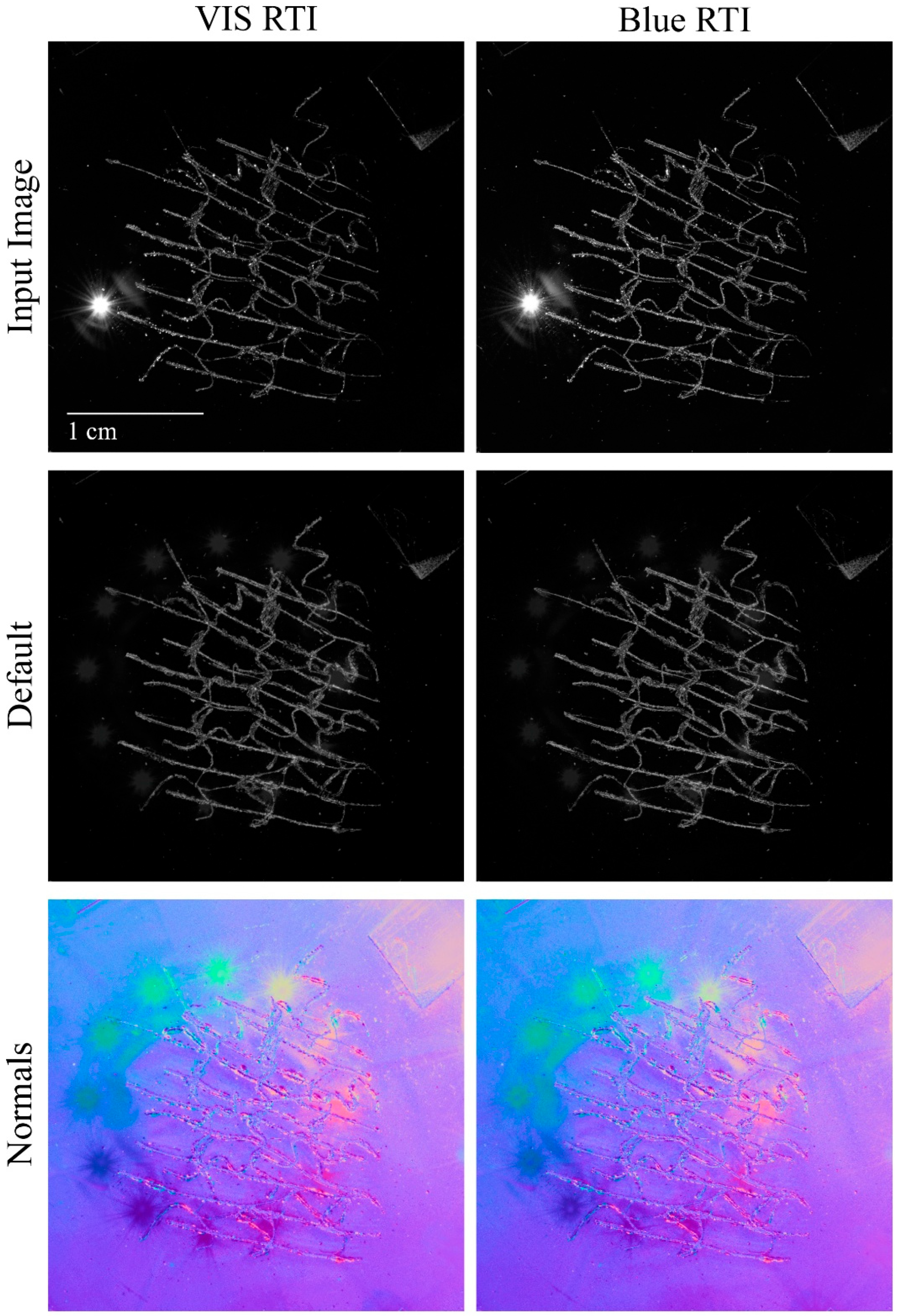
Comparison of the mock-up blue light RTI with the white light RTI revealed a slight improvement for the blue light capture (
Figure 4). The blue light RTI results appeared sharper at some of the worked edges with reduced glare. This subtle difference allowed for the marginally improved visual assessment of surface topography. Attempts to quantify this difference were unsuccessful, however, and the suggestions remain qualitative.
RTI files best presented the morphology of the scribed lines when the light position was set to 0,0. The default rendering mode provided a clear image of the cut areas and reduced the impact of the specular highlights from the lights that are observed in the input images (
Figure 4, top row). Raking light angles did not further emphasize the scribe features from the 0,0 light position. The false color normals visualization proved extremely useful for enhancing the visibility of the scribe lines and the disruptions in the glass surface from these features, despite a small amount of visual noise in the image. With this viewing mode, the crisp chipped edges were well captured and revealed a good deal of detail that could serve as a baseline for the potential monitoring of change over time in the case of an unstable medium. The subtracted images document change over time by clearly showing the additional scribed lines added between “Image Set 1” and ”Image Set 2” (
Figure 5).
3.2. Case Study
Comparison of standard photography with diffuse illumination of the crizzled button with the RTI input images confirms that the latter provides a much crisper and more detailed representation of the glass condition (
Figure 6 and
Figure 7). This difference was noticeable with both the desaturated blue and desaturated white light RTI input sets. We found that an extreme raking light position from the lower light ring of the dome allowed for increased visibility of the crizzled pattern across the glass surface, which highlighted both edges of the disruption and created a shadowed pattern of the cracks (
Figure 6b and
Figure 7b). Similar to the mock-up, the RTI default view reduces the impact of the specular highlights and provides a clear image of the surface degradation (
Figure 6c,d and
Figure 7c,d), and the false color normals visualization enhances the visibility of the surface features (
Figure 6e,f and
Figure 7e,f). Unlike the mock-up, the different raking light angles can aid in the investigation of the surface. The computed RTI files allow for a dynamic investigation of the crizzled surface, which once again yields much greater detail than the standard photography still images.
4. Discussion
RTI conducted in a dome with fixed light positions, including white and blue light, greatly facilitates replicable image studies, which might be adapted to track and compare object surface changes over time. Further, the variety of light positions of a dome allows the user to review and compare individual images in the entire set to find the best still image to record surface details. When reviewing the processed RTI files, the manipulation of the rendering mode settings helps to find the optimal visualization of surface features and provide detailed records of the morphology present.
While the dome supports ease of reproducibility and an automated capture sequence, limitations present challenges for recording small objects like buttons. The level of detail that can be resolved with an RTI capture relates to the resolution of the camera sensor, the focal length of the lens, and the camera–object distance. Though the Nikon 105 mm macro lens is ideal for resolving fine detail, the dome’s structure physically prevents the camera from being moved to the optimal placement for recording minute features such as crizzling. Note that an increased level of detail could be resolved with a smaller object-to-camera distance, which could be achieved using the highlight-based RTI method instead of the dome. However, switching to highlight-based RTI would increase the acquisition time and reduce the ability to accurately replicate the exact process. This conflict of priorities represents a trade-off between getting optimal images versus reproducible ones. Thus, despite the dome’s limitations for generating optimal images, it enables the rapid testing of different lighting situations so that angles and types of light that best document a particular surface feature can be determined and then replicated as desired outside of the constraints of the dome’s geometry.
Monitoring change over time requires the dome, camera, and object to be placed in the exact same positions, and processing such as image subtraction is very sensitive to any discrepancies. For the purposes of this study, the mock-up was placed on a gridded piece of paper with arrows demarcating the exact positioning to allow for re-placement during successive capture sessions. For larger or more complex objects, a jig might be constructed to allow the piece to be placed repeatedly in the same position. Similarly, the initial camera placement can be measured and noted. Our tripod has a measurement feature that displays the exact height of the boom arm.
We found it difficult to focus on the mock-up when preparing the entire set-up for the RTI suite of images; this challenge complicated sharp images when assessing specific details by enlarging the scribed areas in the photography software. Placement of a white brush hair on top of the scribed lines, removed from a Hake brush, facilitated focusing and was a useful aid.
While this study only included qualitative analysis, future research includes investigating ways to quantify observed changes over time and differences between blue light and white light RTI. We also plan to further explore the use of the RTI dome and blue light to investigate cold-worked glass collection objects such as wheel-cut and diamond-stippled designs, with similarly fine-scale surface features.
5. Conclusions
In conclusion, this technical note presented a comparative study of RTI imaging to capture fine surface details present on a glass object, representing features such as crizzled glass or tool marks. Tests concluded that both blue light and white light RTI capture these details well, with a slight preference for blue light. The RTI processing allows for added rendering modes, like normals visualization, that increase the viewer’s ability to assess surface morphology. Image subtraction assists in tracking changes on these surfaces, as long as image sets are produced in a manner that allows for such overlaying. Future work will include research into processes for quantitative analysis of such changes through computational imaging analysis, as explored in Walthew et al. [
20].
Author Contributions
Conceptualization, S.B., J.W. and E.K.W.; methodology, S.B., J.W. and E.K.W.; validation, E.K.W.; formal analysis, E.K.W. and J.W.; investigation, S.B., J.W. and E.K.W.; resources, S.B., J.W. and E.K.W.; writing—original draft preparation, S.B.; writing—review and editing, J.W. and E.K.W.; visualization, E.K.W.; funding acquisition, S.B. and J.W. All authors have read and agreed to the published version of the manuscript.
Funding
Funding for the RTI dome was provided by the Smithsonian Institution’s National Collections Program. Funding for the Multi-band Imaging Kit, including the camera used in this study, was provided by the Smithsonian Institution’s Research Equipment Pool.
Acknowledgments
The authors gratefully acknowledge the Smithsonian Institution’s National Collections Program for their continued support of conservation research at Cooper Hewitt. Thanks also to Anna Serotta, Dawn Kriss, and Chantal Stein (Metropolitan Museum of Art). Sarah Barack ORCID: 0000-0003-1904-6378. Jessica Walthew ORCID: 0009-0005-3586-9720. E. Keats Webb ORCID: 0000-0001-8844-8720.
Conflicts of Interest
The authors declare no conflicts of interest.
References
- Cullen Cobb, K.; Hiebert, M.; O’Hern, R.; Haye, L. Through the Smithsonian glass and what Alice found there: Development of a pan-institutional survey of glass collections at the Smithsonian Institution. In Recent Advances in Glass, Stained Glass and Ceramics Conservation 2022—Preprints of the 6th Interim Meeting of the ICOM-CC Glass and Ceramics Working Group, Lisbon, Portugal, 9–11 November 2022; Gridley, R., Schussler, V., Eds.; International Council of Museums: Paris, France, 2022; pp. 175–182. ISBN 9789895449392. [Google Scholar]
- Brill, R.H. Crizzling—A Problem in Glass Conservation. Stud. Conserv. 1975, 20, 121–134. [Google Scholar] [CrossRef]
- Fearn, S. Continued Studies in the Deterioration of Glass. V&A Conserv. J. 2002, 42, 1–9. [Google Scholar]
- Kunicki-Goldfinger, J.J.; Kasprzak, A.J. Some Observations on Crizzled Glass: Preliminary Results of a Survey of 18th Century Central European Tableware. Glass Technol. 2002, 43C, 364–368. [Google Scholar]
- Koob, S.P. Cleaning Glass: A Many-Faceted Issue. In Objects Specialty Group Postprints; Greene, V., Griffin, P., Eds.; The American Institute for Conservation of Historic & Artistic Works: Washington, DC, USA, 2004; Volume 11, pp. 60–70. [Google Scholar]
- Verhaar, G. Glass Sickness: Detection and Prevention: Investigating Unstable Glass in Museum Collections. Master’s Thesis, Universiteit van Amsterdam, Amsterdam, The Netherlands, 2018. [Google Scholar]
- Hughes-Hallett, M.; Young, C.; Messier, P. A Review of RTI and an Investigation into the Applicability of Micro-RTI as a Tool for the Documentation and Conservation of Modern and Contemporary Paintings. J. Am. Inst. Conserv. 2020, 60, 18–31. [Google Scholar] [CrossRef]
- Mudge, M.; Schroer, C.; Earl, G.; Martinez, K.; Pagi, H.; Toler-Franklin, C.; Rusinkiewicz, S.; Palma, G.; Wachowiak, M.; Ashley, M.; et al. Photography-Based Digital Imaging Techniques for Museums. In Proceedings of the 11th International Symposium on Virtual Reality, Archaeology, and Cultural Heritage (VAST 2010), Paris, France, 21–24 September 2010. [Google Scholar]
- Walthew, J.; Barack, S.; Quinn, A.; Hill, N. Sharing Conservation Imaging Research with the Public. J. Am. Inst. Conserv. 2020, 59, 18–26. [Google Scholar] [CrossRef]
- Artal-Isbrand, P.; Klausmeyer, P. Evaluation of the Relief Line and the Contour Line on Greek Red-Figure Vases Using Reflectance Transformation Imaging and Three-Dimensional Laser Scanning Confocal Microscopy. Stud. Conserv. 2013, 58, 338–359. [Google Scholar] [CrossRef]
- Dittus, A.M. Reflectance Transformation Imaging of Glass Objects. In Recent Advances in Glass and Ceramics Conservation 2016; ICOM Committee for Conservation, Working Group on Glass and Ceramics: Wrocław, Poland; International Council of Museums: Paris, France, 2016; pp. 145–154. [Google Scholar]
- Costello, T. Documenting Physical Evidence of Roman Glass Making Processes. Allard Pierson. Available online: https://allardpierson.nl/blog/documenting-physical-evidence-of-roman-glass-making-processes/ (accessed on 11 June 2024).
- Sharma, D.; Nurit, M.; Rothenhäusler, U.; Schmidt-Ott, K.; Joseph, E.; George, S.; Lombardo, T. Application of Reflectance Transformation Imaging for Visualizing Early Signs of Corrosion in Historical Glass Corrosion. In Archiving 2023: Final Program and Proceedings; Society for Imaging Science and Technology (IS&T): Oslo, Norway; Springfield, VA, USA, 2023; Volume 20, pp. 143–148. [Google Scholar] [CrossRef]
- Kotoula, E.; Earl, G. Integrated RTI Approaches for the Study of Painted Surfaces. In Proceedings of the 42nd Annual Conference on Computer Applications and Quantitative Methods in Archaeology (CAA) 2014; Giligny, F., Djindjian, F., Costa, L., Moscati, P., Robert, S., Eds.; Archaeopress Publishing Ltd.: Oxford, UK, 2014. [Google Scholar]
- Kotoula, E.; Earl, G. Digital Research Strategies for Ancient Papyri: A Case Study on Mounted Fragments of the Derveni Papyrus. In Proceedings of the 42nd Annual Conference on Computer Applications and Quantitative Methods in Archaeology (CAA) 2014; Giligny, F., Costa, L., Djindjian, F., Eds.; Archaeopress Publishing Ltd.: Oxford, UK, 2014. [Google Scholar]
- Kotoula, E. Reflectance Transformation Imaging Beyond the Visible: Ultraviolet Reflected and Ultraviolet Induced Visible Fluorescence. In CAA2015 Keep the Revolution Going: Proceedings of the 43rd Annual Conference on Computer Applications and Quantitative Methods in Archaeology; Campana, S., Scopigno, R., Carpentiero, G., Cirillo, M., Eds.; Archaeopress Publishing Ltd.: Oxford, UK, 2015; pp. 909–918. [Google Scholar]
- Hameeuw, H. Imaging Seals and Coins with Various Light Angles and Spectra: Consequences for Understanding and Representing Colour and Relief. In Digital Imaging of Artefacts: Developments in Methods and Aims; Kelley, K., Wood, R.K.L., Eds.; Archaeopress Publishing Ltd.: Oxford, UK, 2018; pp. 101–118. [Google Scholar] [CrossRef]
- Kriss, D.; Schussler, V.; Driscoll, E.; Bradley, L.; Ford, J.; Pozzi, F.; Basso, E. Materials Characterization with Multiband Reflectance Imaging at the Brooklyn Museum: A New Tool for the Multiband Imaging Kit. J. Am. Inst. Conserv. 2023, 60, 150–167. [Google Scholar] [CrossRef]
- Cultural Heritage Imaging (CHI). Guide to RTIViewer V 1.1; Cultural Heritage Imaging: 2013. Available online: https://culturalheritageimaging.org/What_We_Offer/Downloads/rtiviewer/RTIViewer_Guide_v1_1.pdf (accessed on 19 December 2022).
- Walthew, J.; Barack, S.; Senanayake, N.M.; Lavin, S.J.; Dorris, H.G.; Carter, J.L.W.; Martin, I.T. Imaging Analysis of Scratch Reduction in Poly (Methyl Methacrylate) (PMMA) Plastic with NOVUS Polishing Products. Stud. Conserv. 2023, 69, 88–101. [Google Scholar] [CrossRef]
| Disclaimer/Publisher’s Note: The statements, opinions and data contained in all publications are solely those of the individual author(s) and contributor(s) and not of MDPI and/or the editor(s). MDPI and/or the editor(s) disclaim responsibility for any injury to people or property resulting from any ideas, methods, instructions or products referred to in the content. |
© 2025 by the authors. Licensee MDPI, Basel, Switzerland. This article is an open access article distributed under the terms and conditions of the Creative Commons Attribution (CC BY) license (https://creativecommons.org/licenses/by/4.0/).


