Article

Path of Knowledge for the Assessment of Structural Safety of the Pisan Tower of the Royal Palace of Palermo in Italy

1
Department of Engineering, University of Palermo, Viale delle Scienze, 90128 Palermo, Italy
2
ABGroup Ingegneria srl, Via M. Toselli, 90143 Palermo, Italy
3
Department of Architecture, University of Palermo, Viale delle Scienze, 90128 Palermo, Italy
4
Department of Architecture and Design, Politecnico di Torino, Viale Mattioli 39, 10125 Turin, Italy
*
Author to whom correspondence should be addressed.
Heritage 2023, 6(8), 5818-5847; https://doi.org/10.3390/heritage6080306
Submission received: 12 July 2023 / Revised: 5 August 2023 / Accepted: 9 August 2023 / Published: 10 August 2023
(This article belongs to the Section Cultural Heritage)

Abstract

:
This paper presents the path of knowledge developed for assessing the structural safety of the Norman-age Pisan Tower, which is mostly incorporated into the Royal Palace in Palermo, Italy. Historical, geomatic, and mechanical investigations were conducted and the most relevant results are herein collected and presented. The research path was addressed to specific tasks: identification of the building, geometric surveys, recognition of the sequence of phases of building transformation, detection of the components of the load-bearing structure, structural diagnostic surveys, and investigation of the subsoil and foundations. The explicit vulnerabilities found were mostly confined to the Piazzi library floor, while implicit vulnerabilities were identified in the presence of false walls and in high loads and fillings on the vaults of the last levels. The results of the analyses allowed the individuation of the confidence factors to use in structural analysis models aimed at the assessment of the seismic safety of the building.

1. Introduction

The structural rehabilitation of existing buildings is one of the most active industrial segments in Europe, in compliance with the most recent European Commission policies on sustainability of the built environment. In Italy, more than 60% of existing buildings are masonry constructions, including monumental buildings. Assessment of their structural vulnerability is still a challenging objective, driven by increasing scientific and societal interest in the conservation of the built cultural heritage.
In this context, many recent studies have been devoted to the damage assessment of masonry churches and towers subjected to seismic events or to collapse mechanisms due to static loads (e.g., [1,2,3,4,5]). In particular, knowledge of the current seismic performance level is crucial for the vulnerability assessment of the historical assets in order to evaluate their structural safety and design appropriate retrofitting strategies. However, masonry structures have a highly nonlinear behavior due to their nature, i.e., being composed of assemblages of resisting blocks and dry or mortar joints, with diverse dimensions, thicknesses, and material properties. Different approaches are currently available in the literature for the vulnerability assessment of masonry structures, such as numerical continuum and discrete methods (e.g., [6,7,8,9]), or novel approaches based on the sensitivity-informed parameter reduction of detailed mechanics-based models [10,11]. Among the numerical methods, one of the most efficient is the discrete element method (DEM) used for the simplified micro-modelling of masonry (e.g., [12,13]). The structure is discretized into a system of discrete bodies that can be represented as rigid polyhedral blocks, which interact along their boundaries. The DEM models of masonry structures are able to accurately catch the nonlinear structural responses that lead to the most probable collapse mechanisms, with quite contained computational demand.
In all cases, deep knowledge of the historical documentation of the monumental asset is crucial for understanding its structural characteristics and defining the components of the load-bearing structure as well as the mechanical properties of its construction materials (e.g., [14]).
This paper focuses on the path of knowledge phases for the Pisan Tower, which is a monumental building from the Norman age, nowadays mostly incorporated into the Royal Palace in Palermo, Italy [15,16]. It has been subjected to several architectural modifications during history, leading to its current aesthetic and structural characteristics [17,18].
This paper presents the results of the investigation phase for the Pisan Tower, which was required for the evaluation of the seismic safety of the building. The “path of knowledge” was carried out following Italian Guidelines for the assessment and mitigation of the seismic risk of the cultural heritage (hereinafter, Guidelines) [19]. They indicate the investigation approach, the evaluation criteria for the level of seismic safety, and design indications for interventions. These latter are conceptually the same as those outlined for non-listed buildings, but they have been opportunely adapted to the needs and peculiarities of the cultural heritage, with reference to masonry buildings. The purpose was the formulation of a final evaluation for improvements in safety and conservation, associated with the execution of a seismic retrofit.
The research path can be summarized as the following activities:
  • Identification of the building, localization in relation to particular risk areas, and relationship with the surrounding urban context;
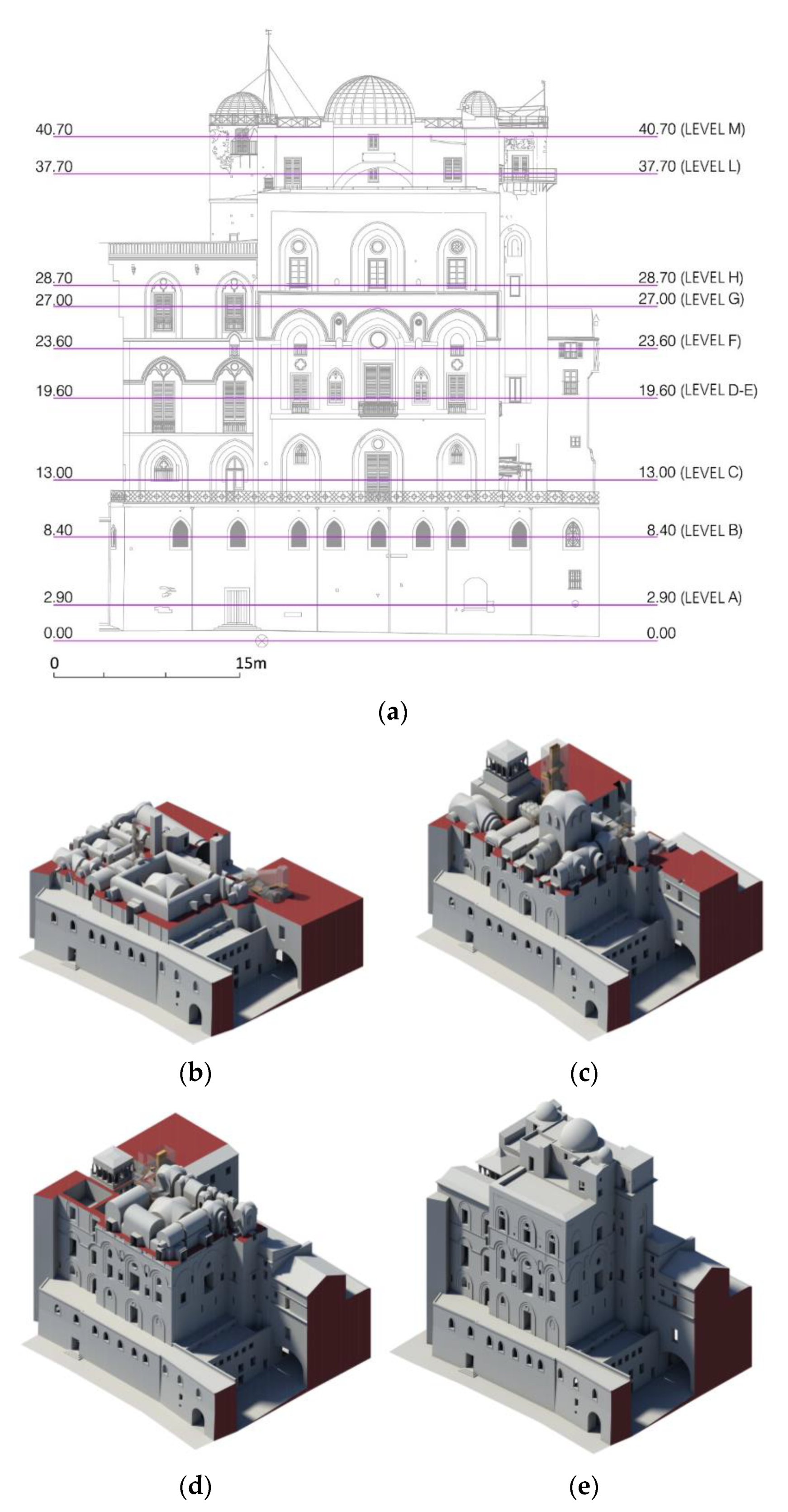
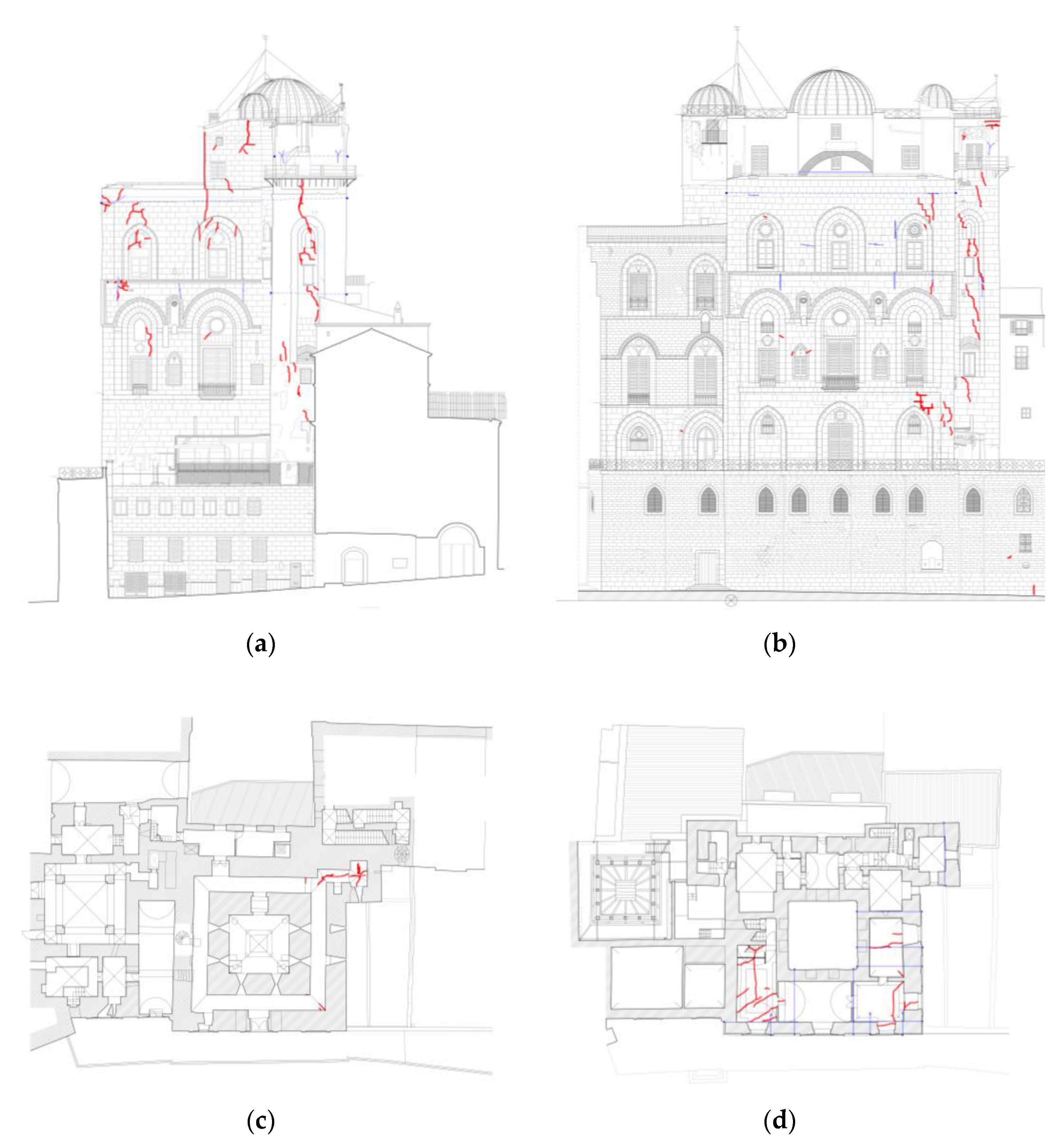
  • Geometric survey of the current state of the building, intended as a full stereometric description of the artifact, including cracking and deformation phenomena, if present;
  • Individuation of the evolution of the building, intended as a sequence of phases of building transformation, from the hypothesized original configuration to the current one;
  • Individuation of the components of the load-bearing structure from material and constructional standpoints, with a specific focus on the realization techniques, the construction details, and the connection between elements;
  • Identification of materials, their decay state, and their mechanical properties;
  • Investigation of the subsoil and foundations, with reference to the variations that have occurred over time and to related instability mechanisms;
  • Identification of the main causes of structural vulnerability.
In this framework, the following paragraphs outline the results of the knowledge acquired regarding the various aspects required for the definition of the calculation model used to propose preliminary strategies of intervention to mitigate seismic vulnerability. The confidence factor was determined for each aspect according to its level of definition as per Guidelines; this allowed grading of the reliability of the structural analysis model, which was considered when evaluating the seismic vulnerability index (or its nominal life).

2. Architectural and Historical Outline

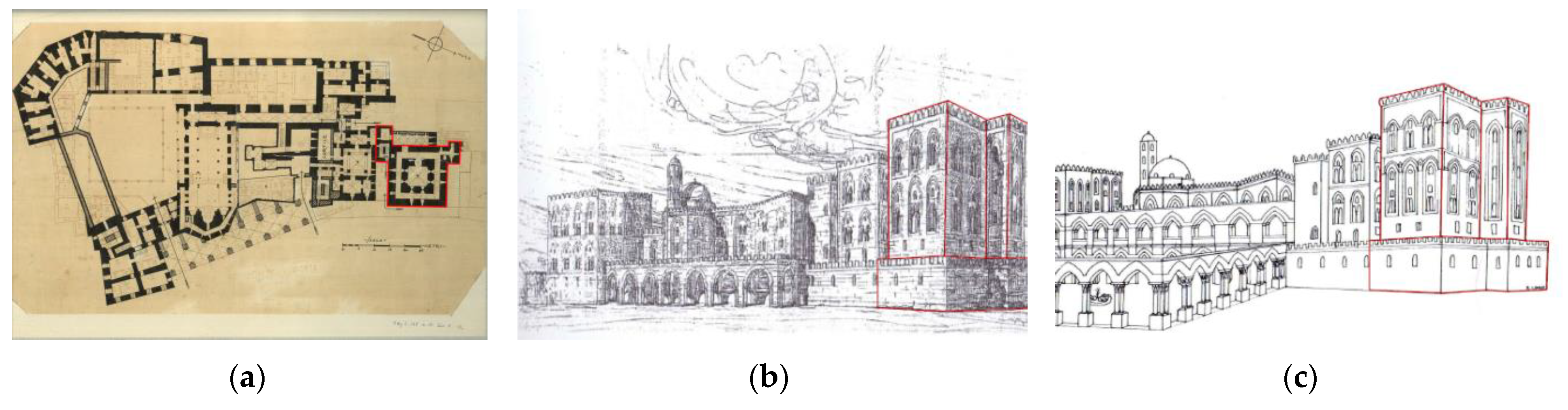
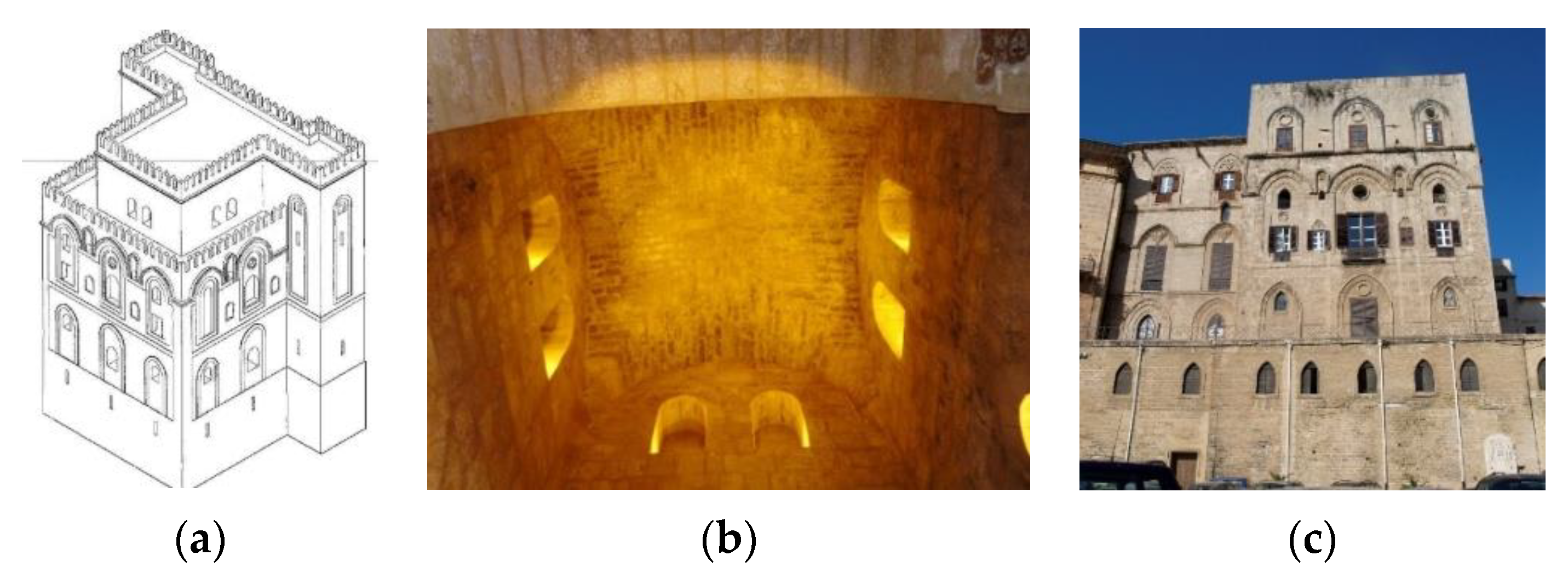
2.1. The Pisan Tower in the Framework of the Norman Palace

The Pisan Tower, which is nowadays mostly incorporated in the Royal Palace of Palermo, is in the part of the historical center named Galca. The whole Palace is located in this area, which is characterized by the presence of a wide adjacent area in the northeast without buildings. Originally, this area had a homogenous plan height, and it was called the “Plane of the Palace”. However, it is currently articulated into different heights, decreasing from the Palace (Parliament Square) toward the historical center (Victory Square). An additional open area, located behind the Palace, is at a lower height than the street level and the adjacent Independence Square and hosts the ancient bastion of the city wall (Figure 1).
The Pisan Tower was part of a defensive system, constituted by four towers at the vertices of the irregular polygon of the plan of the whole Palace. Nowadays, only the Pisan Tower can be easily identified; even though its basement is incorporated into the Palace, its northern front is free at all levels, and the top levels are free on all four fronts.
From a morphological point of view, the planimetry of the building is a quadrilateral with sides about 20 m long; two “turrets”, located at the vertices of the northern and southern fronts, are elevated over the main body of the building. There is an additional internal square, with sides about 9 m long, which represents the central core of the Tower; it is parallel to the external square and is separated from it at each level by a finished “ambulacrum”, which cannot be always identified. The Tower (Figure 2) is about 35 m high, surmounted by an additional elevation (5 m) comprising a rectangle-plan construction, which stops just short of the edge of the eastern façade. On its top there are the three cupolas of the Astronomical Observatory.
The interior of the building has several valuable elements related to different historical ages, which highlight the presence of pre-existing elements from the Arab and Norman ages, the 16th–17th century, and the 18th century. The Tower currently houses a public function, while the rooms of the Astronomical Observatory have been allocated to the Specola Museum. The latter contains several pieces of furniture and tools with high historical–scientific value (Figure 3).
Over the centuries, the Tower has been subjected to several modifications, mainly consisting of additions and reconstruction. Even though the layout of the Tower can still be identified, the large number of modifications has certainly made its identification more difficult, to the point that drawing its simplified planimetry is a very complex operation. In particular, the co-existence of two very different in-use destinations (the public seat of the Regional Sicilian Assembly (ARS) and the “G. Vaiana” Astronomical Observatory), which started in 1973, led to the creation of new hallways and vertical connections. These have been introduced by disemboweling parts of the original structure of the Tower. The constructions that have been added to the Tower over time have affected many of the external prospects. Originally, they were free, but now they have been turned into internal partitions of new spaces; moreover, corresponding roofs that were added have been placed on the external walls, which have also been affected by changes to the openings—closed, then widened, then opened again over time. Despite the many changes over time, these walls can still be identified, and they have been conveniently restored.

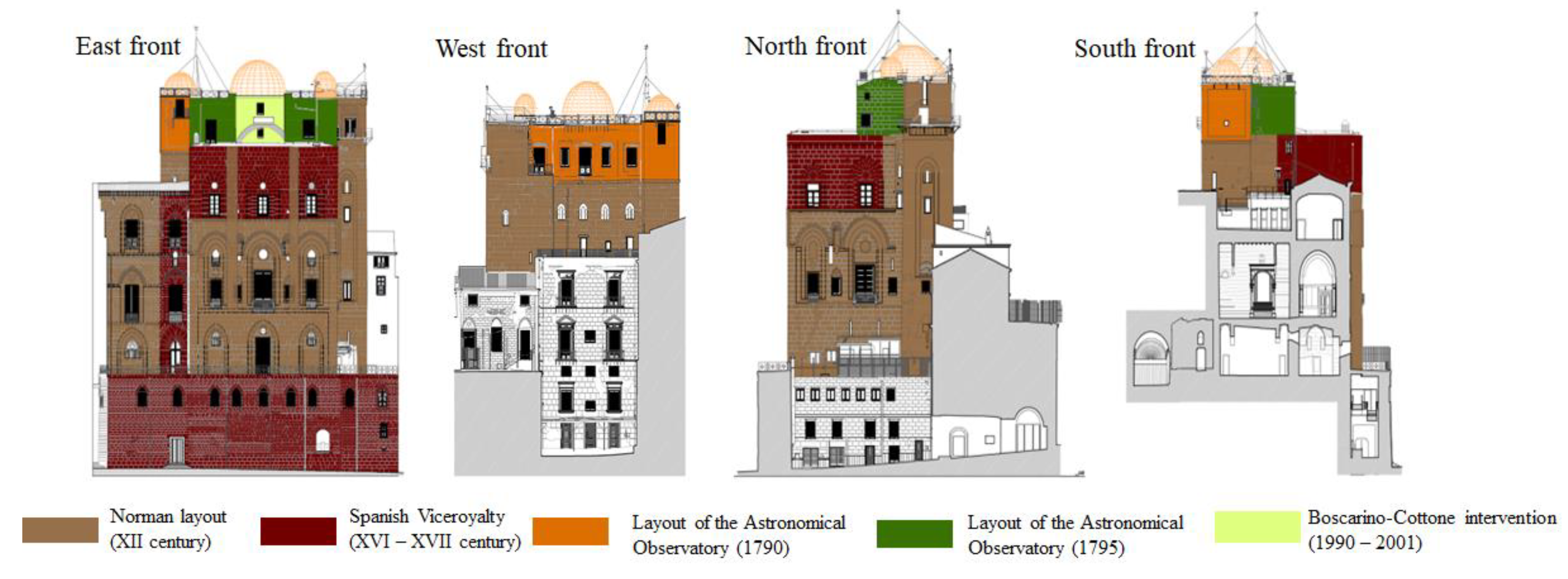
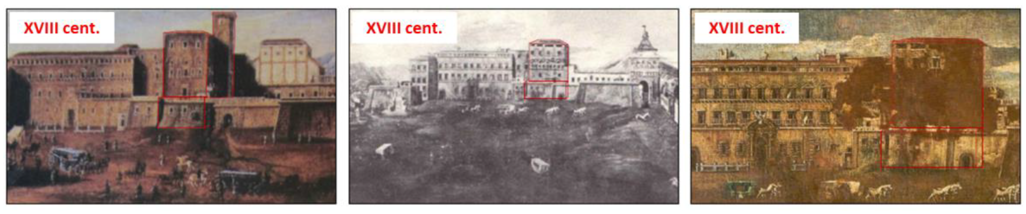
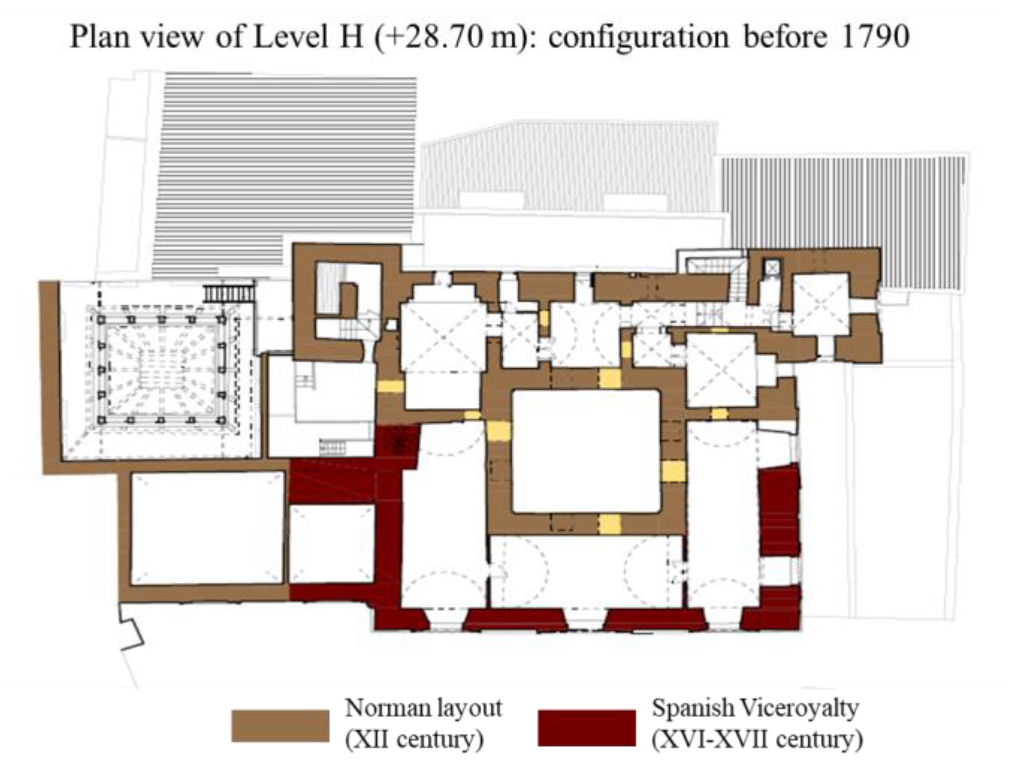
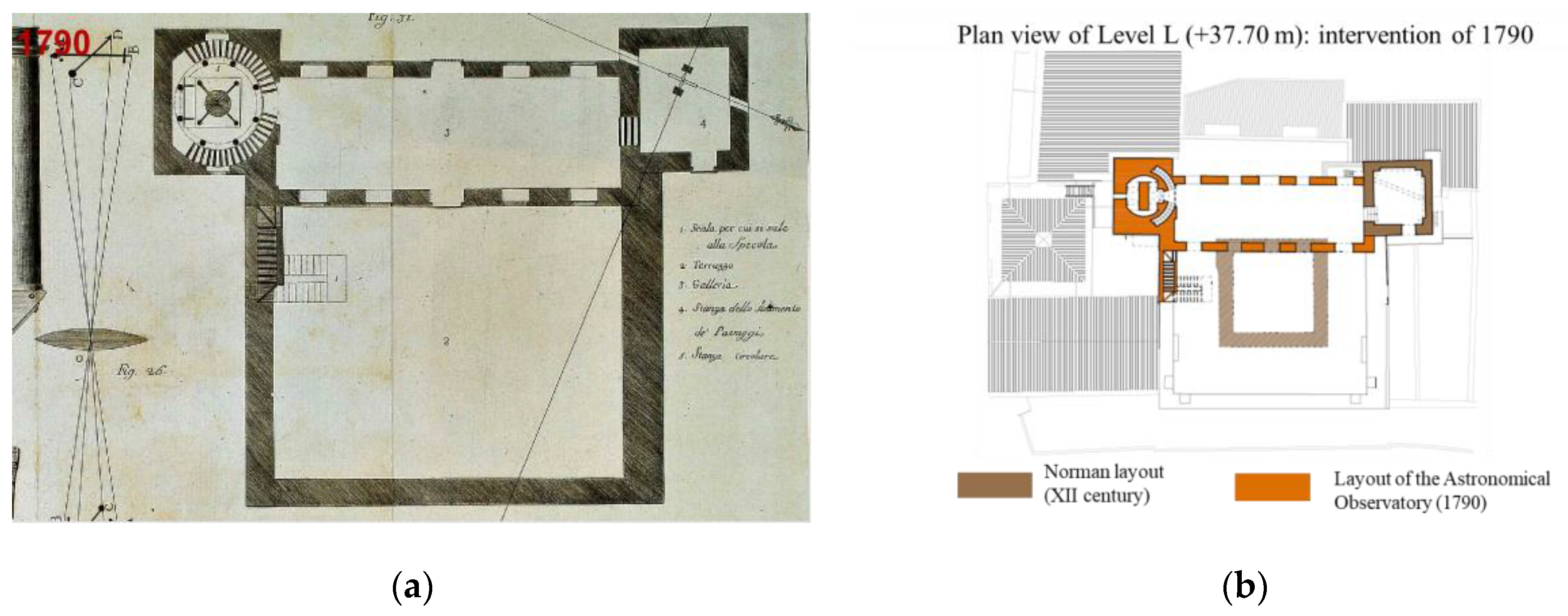
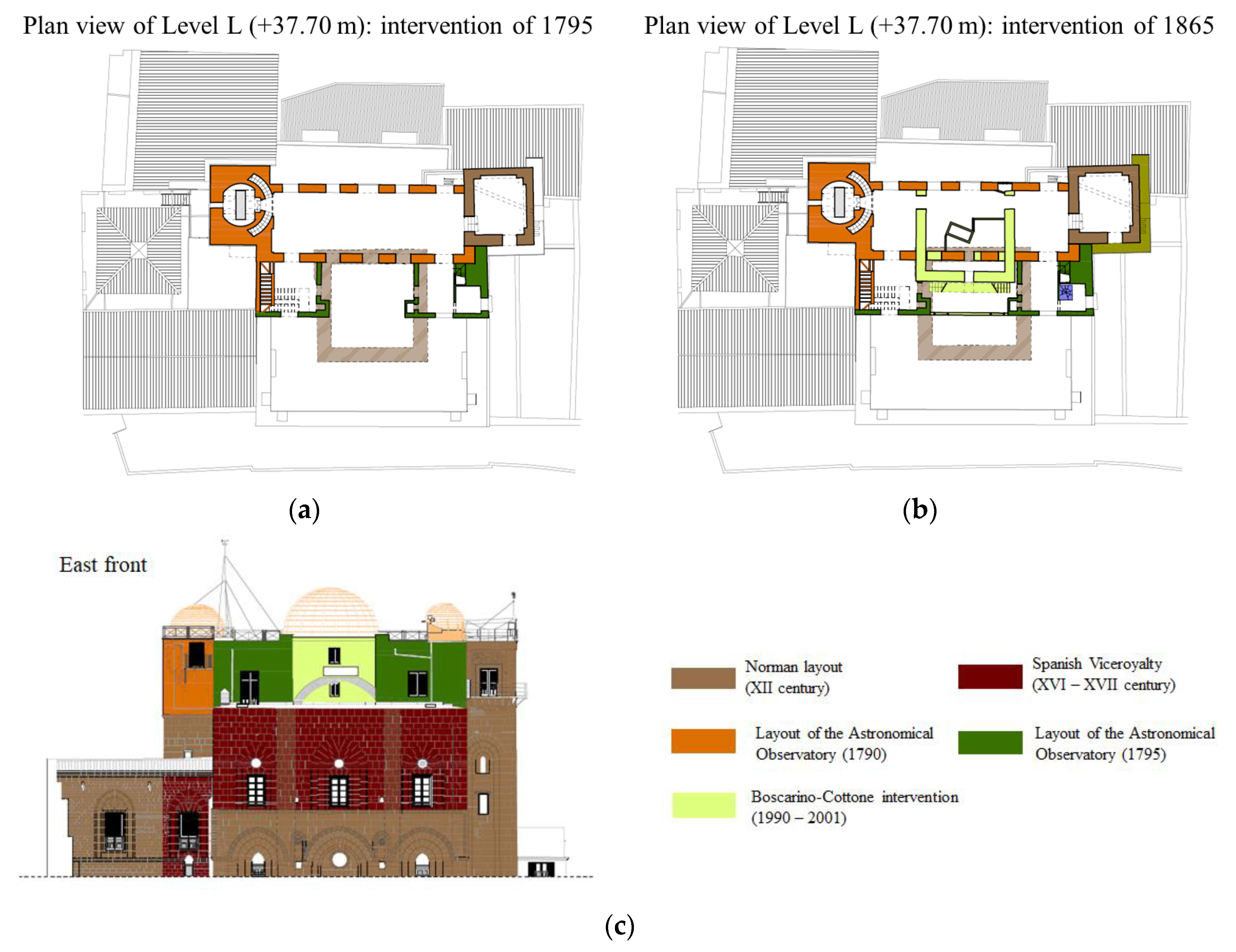
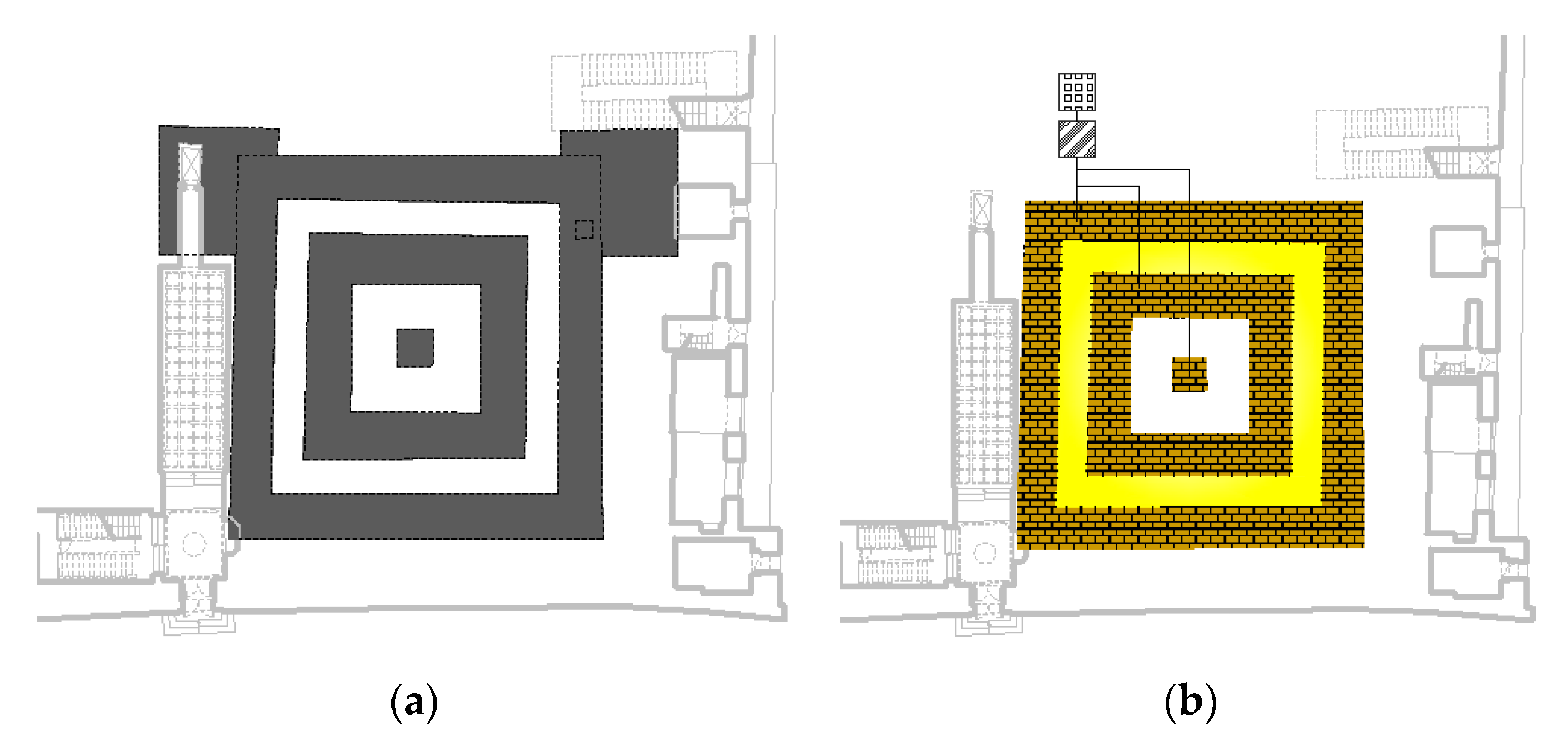
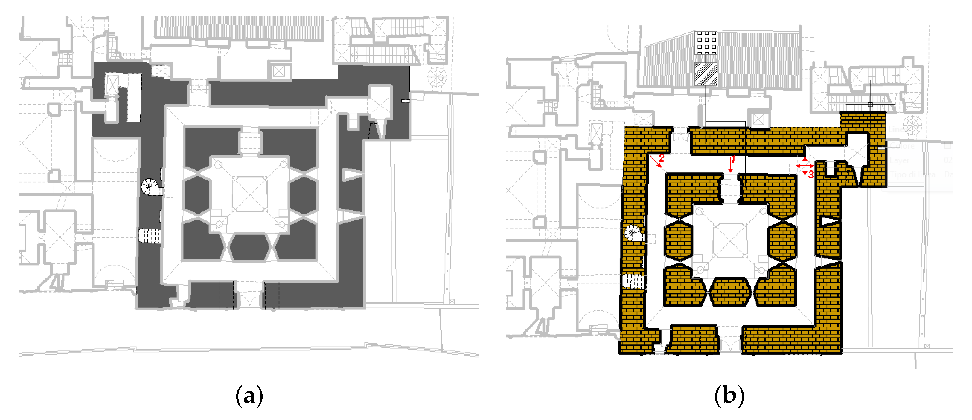
2.2. Evolution of the Constructive Phases

Four construction and transformation ages can be identified, represented in the prospects of the Pisan Tower in Figure 4:
  • Original Norman layout (12th century);
  • Age of the Spanish Viceroyalty (16th–17th century);
  • Layout of the Astronomical Observatory (end of the 18th century—first half of the 19th century);
  • Boscarino and Cottone’s intervention (1990–2001).
Additional “restoration” interventions were performed by Valenti and Guiotto in the first half of the 20th century. As outlined by Guidelines [19], the construction process and the subsequent modifications of the Tower were synthesized and interpreted, highlighting the timeline of the construction works for each part of the building. The purpose was to identify possible material discontinuities and inhomogeneities, both in plan and in elevation (additions, elevations, substitutions of horizontal structures, etc.).
However, due to the historical and constructional complexity, it was not possible to outline every single modification of the Tower over the centuries. In particular, the so-defined original core was characterized by highly confusing information. Conversely, the analysis of the construction process was clearer for the top levels, and much more coherent information was obtained. The inhomogeneity of information was also related to the lack of sources for some historical phases, which is certainly a negative element and represents a gap to be filled. However, since this study was aimed at the definition of local damage mechanisms through reliable calculation methods [19], it did not represent a significant obstacle; in fact, the original core of the Tower was scarcely affected by cracks, and hence showed the highest stability. Conversely, the portion of the Tower with the most significant cracking layout was the most recent, that is, the portion realized from the age of the Viceroyalty to the present day.
Figure 4. The four sides of the Pisan Tower, with indications of the different construction ages in different colors.
Heritage 06 00306 g004
The original configuration of the building in the Norman age was realized with “enormous blocks of cutting stone” (V. Zorić, “Torre Pisana, sede di al-malik Rugar a Palermo”, a report provided by the Technical Bureau of the ARS) [20]. It has been hypothesized that the Norman core of the building reached the current final height of the President’s Room, while the bottom part was presumably protected by ramparts aimed at defending the royal guards, as represented in Figure 5.
A further hypothesis was formulated by V. Zorić; he hypothesized that the central core of the Tower was superelevated above the remaining portion, to allow the enlightenment of the current President’s Room, which is 15 m high (Figure 6a). The paired ogival openings, shown in the photo in Figure 6b, on each of the three free sides of the presumed core, superelevated above the rest of the building, would not be justified unless the abovementioned room, which is now internal as it was incorporated into later constructions, faced the external space (Figure 6c). In particular, the “closing” part of the central core, which creates the straight line of the main prospect of the Tower, as can still be observed today, was realized in the age of the Viceroyalty, as shown in the numerous views where it appears.
According to historical iconography (Figure 7), the building realized in the age of the Viceroyalty was covered by a pavilion and presumably had a lodge under the roof, as proven by the sequence of windows aligned under the eaves line.
In particular, three vaulted spaces were realized to fill the height gap. They were placed on the finishing “parapet” of the flat roof of the current President’s Room, through a masonry superelevation realized about four centuries after the previous one; this led to the current floor of the Piazzi Library (Figure 8). Two of the abovementioned vaulted spaces were placed perpendicular to the wall of the main prospect on the east side, while the third one serves as a connection between the others and is placed parallel to the line of the prospect. If the vault on the south side is still the original one, the three vaults were barrel vaults in calcarenite ashlars. The vaults were based on the shear walls of the Tower on one side and on the two arches on the other side, with a conveniently lower ridge height, to generate the additional vault of the perpendicular passageway (Figure 8). The latter was placed on the superelevated shear wall of the main prospect, and the parallel one in the pre-existing internal core of the Tower. Hence, this wall was not realized with the same crafts and clamps as the original one; even if it was well made, it was an addition to a structure from many centuries before.
This reconstruction was also inferred from the integrative surveys carried out in the framework of this study. It suggests that a considerable mass had been built over the pre-existing Norman structure; this mass was even greater due to the significant filling layer (a width of over 150 cm) detected through integrative endoscopic surveys. Consequently, the load excess could be one of the concurring causes that have contributed to the generation of cracks in the vaults of the underlying rooms, now part of the President’s Room.
The construction of the Astronomical Observatory dates back to the end of the 18th century. It was the next substantial modification of the Tower, consequent to the readjustment of the rooms, with a further expansion due to the superelevation of the top level. In fact, in 1789, Giuseppe Piazzi (the first director of the Astronomical Observatory) and the architect V. Marvuglia were put in charge of the delegation of the Royal studies for the “…realization of the Astronomical Observatory on the roof covering of the Pisan Tower in Palermo…” [21].
Hence, the consequent superelevation (Figure 9) consisted of a room placed on the roof covering, comprising a windowed rectangular “gallery” (Figure 9a), based on the west side of the wall and on a new wall on the east, opportunely based on the internal core of the abovementioned double row of the Tower (Figure 9b).
The gallery was built in calcarenite ashlars and covered by plain timber floors; it was adjacent to the Norman north tower, and to the south tower with the superelevated top level. Of course, the layout of the new floor required the installation of a staircase, which was placed behind the Piazzi Library, perpendicular to the south wall of the Tower. The staircase almost emptied the wall, as it occupied its whole width, and it reached the external terrace (Figure 9). There was no additional internal connection with the to-be-built gallery.
A few years later, In 1795, a porch was realized, presumably because of this circumstance, and it was replicated on the north side (Figure 10a) to achieve symmetry. These consisted of two quadrilaterals, with two very small, slightly superelevated turrets in the free internal corners. During the construction work for the porches, the planimetry of the lower floor was modified as well (floor of the Piazzi Library); the room on the southern end was then assigned to the Piazzi Library and the room on the northern end was used as the office of the director of the Observatory and remained a central passageway. Then, in 1795, the two porches were connected with a thin wall; seventy years later, in 1865, the gallery was internally divided into three different spaces with thick walls in calcarenite ashlars, connected to an additional thick transfer wall. A wooden scissors soft ladder—no longer existing—was placed beyond it (Figure 10b). Moreover, the system allowed the realization of a wide square space to raise the large dome with a circular drum (Figure 10c).
Boscarino and Cottone’s intervention in the 1990s was performed after the damage due to the 1968 earthquake. In particular, the floor of the President’s Room is still severely damaged, as well as the room with the Piazzi Library, which is even more damaged, with a strongly cracked vault, shored up in a currently visible safety intervention, which should have been provisional.
In 1985, almost 20 years after the earthquake, the general study realized by S. Boscarino highlighted the “…precarious conditions of most rooms, with instability phenomena on floors and roofs, and of poor roof coverings and windows…” (Consolidamento, restauro e sistemazione dei locali dell’Osservatorio Astronomico nel Palazzo dei Normanni, Palermo, 1985, published by the Technical Bureau of the University of Palermo, in Italian), and proposed a restoration intervention for the severe state of decay, which resulted in the “Extraordinary maintenance project for the rooms of the G.S. Vaiana Astronomical Observatory in the Norman Palace in Palermo” by A. Cottone. The intervention restored the state to that at the time of the construction of the Observatory by eliminating the partition walls that divided the gallery; only the scissors ladder differed, as it was realized anew in steel inside the residual cavity between the wall of the room and the transfer wall of 1865. The intervention involved the two floors at 37 and 40 m, respectively, which corresponded to the spring line and the roof covering of the gallery. At the level of the spring line of the gallery, two slab spans were realized externally, above the vaults, with steel profiles and hollow flooring blocks, sustained by rim joists and by a diagonal crossbeam (Figure 11a,b). On the other hand, the central vault was simply reinforced on the extrados through the insertion of metal dowels and the addition of reinforced concrete to support the reticular steel column which sustains Mertz’s equatorial refractor telescope at the upper level (Figure 11c). The current state completely coincides with this last outlined intervention.

3. Materials and Methods for the Identification of the Structural System

The building was surveyed by levels, whose heights are indicated in Figure 12a. Figure 12b–e also show the main axonometric sectional views of the Tower obtained from the 3D geometric model in order to clarify the structural complexity of the system. For each level, the reported surveys were performed on the vertical structural component intersected by the section plane, and the horizontal structures that serve as roof coverings for the respective levels. The floors of the Tower, which correspond to the section representations, are denoted with letters from A to M (Figure 12), while all the rooms are indicated with progressive numbers following the letter.

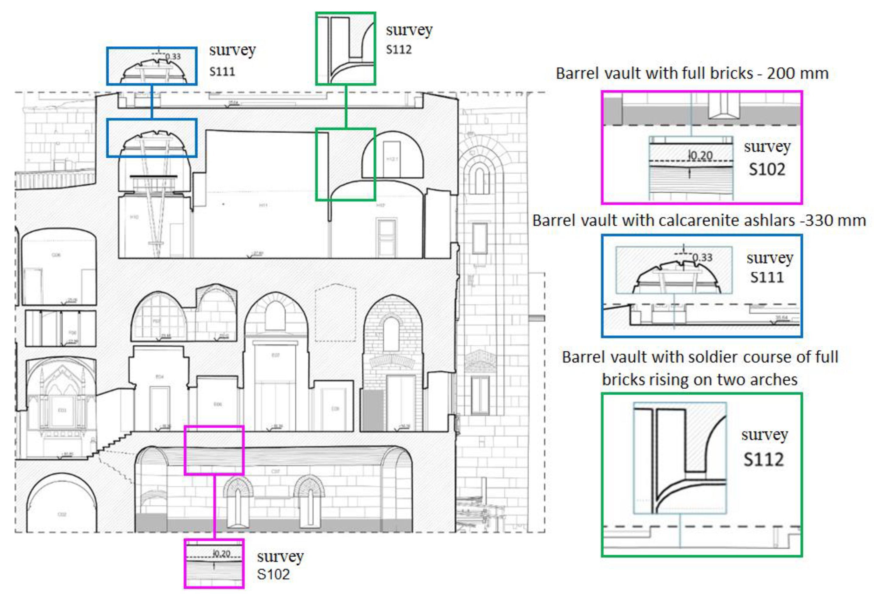
3.1. Surveys for the Detection of Materials and Bearing Structures

In 2012, a detailed geometric laser scanning survey was carried out by the company Officina per le Arti Opera, a start-up of the University of Palermo. The survey and the drawings (plans, fronts, sections) strongly supported the analysis of the structural features of the Tower. Laser scanning and topographic survey allowed an accurate superimposition of plans, which allowed checking the match between loads and bearing elements at all levels; furthermore, the data on previous structural restorations (e.g., iron chains) were reported both in drawings and in the 3D model of the Tower. The survey shows that the Tower has a masonry structure, and the wall widths range from 250 cm—on the ground level—to around 40 cm for the “gallery” of the Astronomical Observatory. The walls consist of calcarenite ashlars, in different arrangements and typologies; there is exposed masonry up to the height of 28.70 m, then the walls are covered with stone slates at the level of the Piazzi Library, as in the underlying wall texture, with plaster finishing at the top level of the Observatory.
Apart from claddings, the uncertainty concerning wall typologies also includes the vaults, as only in a few cases were the width and the constitutive material determined through integrative tests.
The area of the building where the structural organization has been interpreted most extensively is the ancient Hall of the Observatory, with the two adjacent porches and the upper part sustaining the geodetic domes. In these more recent parts, the survey identified floor slabs with metal profiles or trusses and hollow flooring blocks, laid with edge beams.
In addition to the available data and those obtained from direct observation of the current state and in-depth historical research, data related to the geometry and typology of the most damaged structural elements were acquired through endoscopic surveys; they were all located in the most damaged areas of the Tower.
The results of these integrative surveys allowed the determination of both qualitative and quantitative data. In particular, a mostly incoherent infill was found above the vaults, in the northwest corner of the ambulacrum surrounding the Treasure Room, also called the Mint Hall (sample S103), in correspondence with an edge of the interior wall of the south tower on the same level (sample S104), and in the Director’s Office on level H (samples S109 and S110). The width of the barrel vault of the ambulacrum surrounding the Treasure Room (sample S102) and of the barrel vault above the Piazzi Library (sample S111) were surveyed. Despite the latter being currently covered by plaster, the constituting material was determined to be calcarenite ashlars. Finally, the real current structural configuration of the vault on the passageway between the Piazzi Library and the Observatory Director’s Study was obtained, as it is hidden by partition walls and false ceilings. Horizontal sampling on a wall (sample S112) highlighted that the barrel vault had actually been realized with a soldier course of full bricks and that it rises on two arches: one of them is visible, while the other one is hidden by the abovementioned partition walls. Figure 13 shows the locations of samples S102, S111, and S112, which provided these results.
In addition to the geometric data on structural elements and knowledge about the typologies and materials—which allowed estimating loads and their repartition on the walls—it was necessary to individuate the degree of connection between walls and the presence of cracks. For this purpose, the representation of the crack patterns was limited to the cracks on the portions of walls and floor slabs that were visible in the drawn elevations and sections.
During the long life of the Royal Palace, many significant seismic events have occurred, and these have produced damage, which has been documented since 1693 [22] because of the various architectural modifications and the proximity of the Kemonia creek, which had a higher flow at that time. In particular, the Pisan Tower suffered significant damage during the 1968 earthquake, leading to the unavailability of some rooms on the level of the Observatory, with severe cracks in the vault of the Piazzi Library, which is currently still shored up for safety reasons. Comparison should be made of the current crack pattern—possibly worsened by the recent earthquake on 6 September 2002—with surveys of previous cracks; however, there was no available documentation for this purpose. Figure 14 shows some of the technical drawings by Officina per le Arti Opera, which illustrate the crack patterns.
In addition to endoscopic surveys, core sampling and ground-penetrating radar were used at the various levels of the buildings. In particular, core sampling and endoscopic surveys provided useful information for the reconstruction of layers and constituting materials, in addition to some values of compression resistance inferred from the extracted core samples.
At level A (height 2.90 m), which is the first inspectable level and represents the oldest part of the construction, core sampling revealed the presence of double masonry walls with calcarenite ashlars and drywall joints, a sandwiched infill of about 90 cm, and single masonry walls in calcarenite ashlars and mortar. The masonry walls have an average width of 240 cm.
On level B (height 8.40 m), the building is only partially inspectable. Core sampling detected a 244 cm wide masonry wall, whose interior part has poor mechanical characteristics and/or infill, a central infill between 244 and 484 cm, and a final layer in compact masonry. GPR performed from the floor of the upper level showed a central reflection, which can be explained by the presence of vaulted slabs.
Level C (height 13 m) of the building is entirely inspectable. Various survey techniques were used: core samples, endoscopic surveys, and GPR with flat jacks. Core sampling allowed the acquisition of compression strength values, in addition to inspecting inside the hole; endoscopic surveys provided useful data for the reconstruction of layers and constituting materials; GPR provided qualitative indications which were scarcely useful for structural purposes, as they only revealed internal reflections in masonry, hinting at the presence of niches and/or brick inserts; finally, single flat-jack surveys provided information on operating tension values. Additionally, cone penetration tests were performed on mortars, providing compression strength values between 2.1 and 7.9 MPa. Tests with single flat jacks were performed in couples, in very close places; however, they reported notable differences, presumably due to the significant width of the investigated masonry in relation to the area of the flat jack. Surveyed operating tension values showed a high work rate in masonry walls, up to 18.91 daN/cm2. Endoscopic surveys on the horizontal structures allowed identification of the characteristics of the infill of the vault under the room adjacent to the President’s Room; the infill is heterogeneous and incoherent, and the width of the vault above the east ambulacrum is equal to 20 cm.
Levels D–E (height 19.60 m) of the building were entirely inspectable; aside from the President’s Room and the ARS, all the other rooms are used as offices. The horizontal and vertical structural components at this level were partially hidden by an exposed faux masonry plaster; to identify their geometric and material components, only endoscopic surveys were used, to limit the invasiveness of the surveys and the interference with other activities. Many data were collected through archive historical investigations; in fact, this level was the subject of a wide and systematic intervention by F. Valenti in 1929. No specific investigations were performed on vertical load-bearing structures, while vertical endoscopic surveys on horizontal structures only showed the presence of heterogeneous and incoherent infill.
Level F (height 23.60 m) has some mezzanine rooms which can be accessed from the lower level. These rooms are used as offices and archives. No specific surveys were performed to identify the wall typology of the horizontal and vertical structural components on this floor, even though they were partially covered by an exposed faux masonry plaster. Only cone penetration tests were carried out on the mortars, which showed them to have poor mechanical properties in the vertical walls (3.7 MPa) and good ones in the window vault on Parliament Square (5.2 MPa). The hypotheses formulated for the load-bearing system of the Tower and for the materials of the structural components were supported by the many available historical and archival data from F. Valenti’s intervention.
Level G (height 27 m) also hosts some of the rooms of the Astronomical Observatory. At this level, it was possible to directly examine and inspect the south and west walls of the Tower, and its two towers. The only performed survey was a cone penetration test on the mortar (good mechanical properties of compression strength, equal to 5.7 MPa), but visual and documentary examination allowed the acquisition of useful indications for the reconstruction of the building. No surveys were performed on the horizontal elements.
Level H (height 28.70 m) is currently the floor of the Piazzi Library, which hosts rooms of both the Astronomical Observatory and the ARS. The rooms of the Observatory, mainly used as offices and a library, were severely damaged by the 1968 earthquake; still today, they are damaged and unusable. The rooms of the ARS were involved in Valenti’s intervention, which reconfigured them by also intervening on vertical and horizontal load-bearing structures. At this level, the following tests were performed: cone penetration tests on mortar, double flat-jack tests, and static and dynamic load tests. The performed tests allowed assessment of the mechanical characteristics of the materials and the operating tension. Two endoscopic tests were performed as well, to determine the width of the vault of the Piazzi Library and the width of the adjacent wall.
Cone penetration tests on the mortars of the walls revealed low mechanical properties (2.7 MPa). Single and double flat-jack tests detected very low operating tension (0.5 daN/cm2) and compression strength (11.92 daN/cm2) values, and a high elastic modulus (E = 1728 MPa), within the surveyed masonry typology. Concerning horizontal structures, the static load test on the tie rods provided a value of σ = 36.1 daN/cm2 when considering a fixed support and σ = 476.5 daN/cm2 when considering a hinge. The latter is consistent with the value of σ = 549.1 daN/cm2 determined with the dynamic test.
On the L level (height 37.70 m) are the Museum of the Astronomical Observatory and a wide panoramic terrace overlooking Parliament Square. The following tests were performed for the geometric and material identification of the horizontal and vertical structural components on this level: cone penetration and GPR tests. The surveys provided qualitative, scarcely useful data; however, available historical and archival information on Boscarino and Cottone’s intervention in the 1990s made it possible to fully hypothesize the structural and material system of the Museum. The cone penetration tests on the mortars of the walls detected poor mechanical properties (3.7 MPa), while no surveys were carried out on the horizontal elements.

3.2. Structural Identification

The surveys performed and the information collected showed that the vertical load-bearing structure of the Tower consists, on level A, of two concentric quadrilaterals in the planimetry, with walls wider than 2 m, and two turrets at the vertices of the west side of the Tower, as represented in Figure 15a. These walls have been realized with a wall in large (70–100 cm) calcarenite ashlars, dry-placed and/or with low-width mortar joints. The wall was considered to show good workmanship and the ashlars have excellent mechanical properties, as shown by the high value of the compression strength of the extracted core samples. The material between the two squares of the Tower can be associated with an infill, mainly constituted by crushed ashlars, masonry with scarce mechanical properties, and incoherent materials (Figure 15b).
The surveys performed and the information collected at level B repeated and confirmed the same structural layout as the lower level, consisting of two homothetic quadrilaterals with wall widths above 2 m, in calcarenite ashlars, dry-placed and/or with mortar (Figure 16a). Today, as in the Norman layout, the south turret is mainly used for vertical connections. The structural layout of the Tower has been presumably subjected to modifications during the complex and intricate evolution of the Norman Palace. At this level, the wall, which is partly visible, consists of calcarenite ashlars and variable-width lime mortar joints. The performed tests showed that the ashlars have good mechanical properties; however, these were lower than the values found at the lower level. The infill of the core between the two masonry squares is heterogeneous and incoherent, while in the internal core it is constituted by crushed ashlars with variable size and resistance (Figure 16b).
Level C has a completely exposed structural layout, consisting of two concentric quadrilaterals, divided by an ambulacrum with a barrel vault covering and two side turrets (Figure 17a). The masonry walls are in large calcarenite ashlars and lime mortar. The mechanical parameters of the ashlars were only available for the exterior of the east wall, and the resistance values were aligned with those of the lower level. The values for the operating tension of the masonry wall of the external square were very high; this is probably incompatible with the resistance of the masonry (Figure 17b).
On levels D-E, the structural layout of the concentric quadrilaterals can be detected even if the walls are significantly set back from the lower level (Figure 18a). Moreover, the walls of the external square are intermitted by wide and numerous openings (doors, windows, rooms, and staircases). The President’s Room has two different heights, while the other rooms are mainly double-height or have timber roofs. Superintendent Valenti, during the 1929 restoration intervention, performed several modifications to the structural layout. He demolished many mezzanine rooms, which had presumably been realized in the period of the Spanish Viceroyalty, and relocated some masonry walls to restore the Norman layout. The numerous performed interventions and the finishing with exposed faux masonry plaster were an obstacle to the precise definition of the wall typologies. Figure 18b shows a possible hypothesis, reconstructed solely on the basis of the historical documentation found.
At level F, the two mezzanine rooms used as offices were examined. The structural layout and related considerations (Figure 19a) were the same as for the lower level (19.60 m). During the 1929 restoration intervention, Superintendent Valenti performed several modifications to the structural layout. He demolished many mezzanine floors on this level and only left the ones that are currently being examined. Several extensive reinforcement interventions were performed on the vertical load-bearing structure through local rebuilding and, sometimes, demolition and reconstruction. The masonry walls used in these interventions were both in aerated bricks and calcarenite blocks (Figure 19b); however, the large number of interventions and the use of an exposed faux masonry plaster finishing complicate the precise definition of the wall typologies.
Level G includes the rooms of the Astronomical Observatory adjacent to the south and west sides of the Tower. As has been mentioned, these were involved in the restoration intervention in the 1990s by Boscarino and Cottone. The intervention exposed the load-bearing structure on this level, allowing us to observe that it can be substantially associated with the original Norman construction (Figure 20a) and that it consists of large calcarenite ashlars and lime mortar (Figure 20b).
At the level of the Piazzi Library (level H), which hosts rooms of both the Astronomical Observatory and the ARS, the load-bearing structure provides the layout with concentric quadrilaterals (Figure 21a). The compactness and rigidity of the system are notably reduced by the narrow width of the walls, and by the numerous openings. As discussed in the previous paragraphs, the east side of the Tower probably represents an addition from the period of the Spanish Viceroyalty. Hence, techniques and materials differ significantly from the Norman construction (Figure 21b). This circumstance was also confirmed by the mechanical characteristics surveyed in the Spanish masonry, which was characterized by low values of compression strength as compared to those of the Norman masonry and to the suggested values for masonry walls in soft stone ashlars. These intrinsic flaws in the masonry, together with the presence of many transfer walls between the two squares in the load-bearing structure of the Tower, have certainly led to a relevant vulnerability. The effects of the 1968 earthquake and the constant and abundant infiltrations from the terrace of the upper level have produced several instability phenomena, including diffuse—and worrisome—cracks in both vertical and horizontal structural components. Following these damages, the rooms of the Observatory were shored up and made inaccessible. The cracks in the floor slabs are often extended in the walls, hence disrupting the wall structure and leading to additional vulnerability.
At level L, the current Museum of the Astronomical Observatory is substantially a superelevation performed at the end of the 18th century by Piazzi and Marvuglia, and it was subjected to several integrations, modifications, adaptions, and an extended and complete restoration intervention by Boscarino and Cottone, who restored the layout of the original Observatory. At this level, the structural layout no longer has a rigid system with two concentric quadrilaterals; instead, a single hall connects the south and the north turrets (Figure 22a). Boscarino and Cottone’s intervention included the demolition of the partition walls in the main room, and the substitution and/or the reconstruction of all the floors of this and the upper level, in addition to the construction of a new dome based on an octagonal steel drum. Since the original construction, the walls had been almost entirely in masonry, with calcarenite ashlars and mortar joints (Figure 22b). They were then subjected to repeated reinforcement interventions, using the techniques common at the times of the interventions, including local rebuilding with aerated bricks, reinforced plaster with an electro-welded mesh on the two sides, re-pointing of mortar joints, substitution and/or realization of new steel lintels, and construction of new steel tie-rods. These interventions improved the masonry resistance, but they did not cure the vulnerabilities of the vertical load-bearing structural components at this level, which are mainly related to the presence of some transfer walls. Among these, the wall on the east side—which provides a basement for the drum of the central dome—must certainly be investigated. At the walking level of the museum (36.18 m), Cottone and Boscarino’s intervention removed the infill and realized new floors in I-beams and hollow flooring blocks detached from the vaults, which then lost their load-bearing structural role. Instead, the vault of the central room was reinforced so as to support the equatorial telescope. At the upper level, that is, the roof covering of the museum of the Observatory, the pre-existing timber roofs were substituted with new slabs, steel I-beams, and hollow flooring blocks.

3.3. Mechanical Characterization of Masonry

Based on the collected data and on the performed surveys, this section is dedicated to the mechanical characterization of the materials, with a particular focus on the masonry of the vertical and horizontal structural components. Since there are no reference data or archives for masonry walls like those of the Pisan Tower, in accordance with Guidelines, the mean values of the mechanical parameters defined in Table 1 and Table 2—which report the values from C8.5.I and C8.A.2.2 of the Circular of NTC2018 [23,24]—were adopted. The detected masonry walls mainly belonged to three typologies among those in Table 1 (Table C8.5.I): masonry in quarry stones with a good texture, masonry in soft sone ashlars, and masonry in full bricks and lime mortar. The second typology was subdivided in order to distinguish the masonry typologies found in the Tower from historical, construction, and mechanical standpoints. The following typologies were introduced:
-
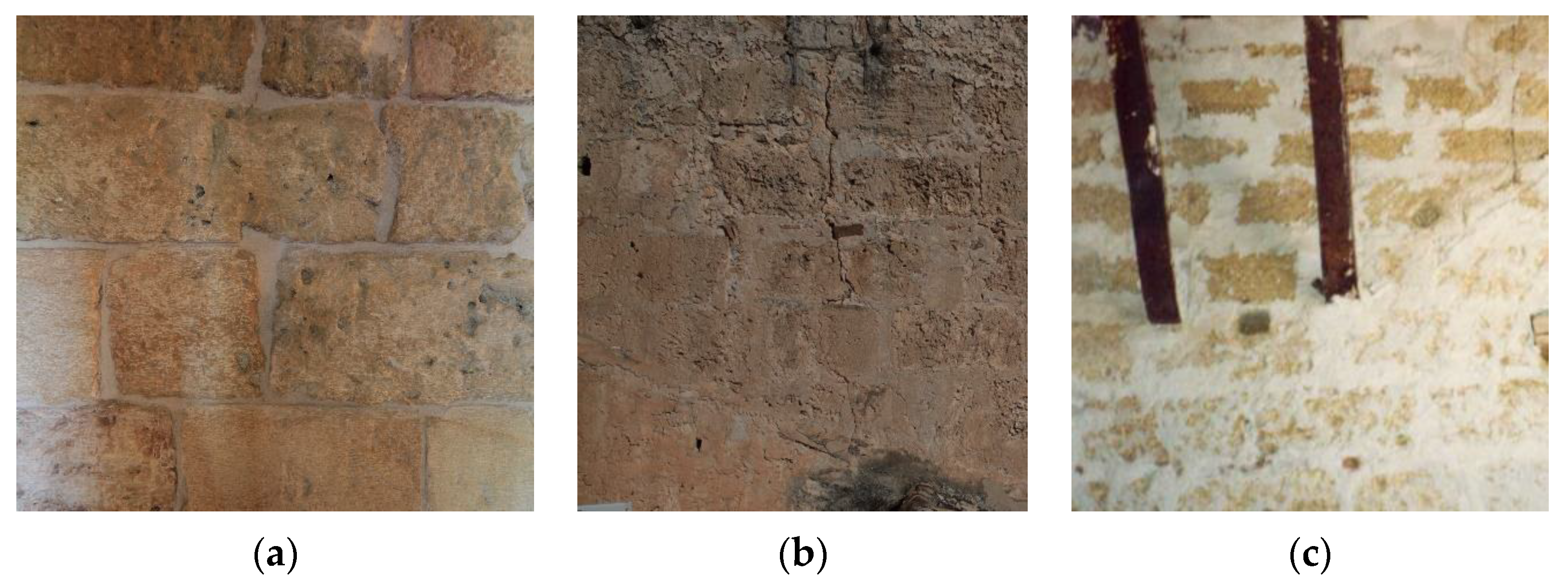
Masonry in soft stone ashlars (tuff, calcarenite, etc.) of the Norman period (Figure 23a);
-
Masonry in soft stone ashlars (tuff, calcarenite, etc.) of the period of the Spanish Viceroyalty (Figure 23b);
-
Masonry in soft stone ashlars (tuff, calcarenite, etc.)—19th century—Astronomical Observatory (Figure 23c).
Figure 23. Masonry typologies: (a) Norman era; (b) Spanish era; (c) 19th century.
Heritage 06 00306 g023
The values in the previous table are related to poor-quality masonry walls without clamps and connections between parament. For better-quality or reinforced masonry, mechanical characteristics can be obtained from those values by applying nondimensional corrective coefficients (Table C8.5.II) that vary according to masonry typology, mortar quality, presence of double courses and trimming, transversal connection, and mortar or reinforced plaster injections.
With reference to the first and third typologies identified in Table 1 (C8.5.I), the mean values were chosen from the table. The mechanical properties of the three new typologies were defined in relation to the available data and surveys performed. Specifically:
-
Masonry in soft stone ashlars (tuff, calcarenite, etc.)—Norman Period was characterized according to the properties of its constitutive elements (mortar and ashlars), as suggested by Guidelines and at paragraph 11.10 of NTC2018. The availability of compression strength tests performed on core samples extracted from ashlars and cone penetration tests on mortars allowed evaluation of the compression strength of the masonry fk, conservatively assumed to be equal to fm. The adopted approach was the one reported in paragraph 11.10.3.1.2 of NTC2018 for masonry constituted by natural elements, with fbk = 5.37 MPa and a mortar conservatively classified as M2.5. The values were used to obtain the compression strength of masonry fk = 3.07 MPa through Table 11.10.VII of NTC2018. With a similar procedure and the adoption of Table 11.10.VIII of NTC2018, the value of fvk0 = τ0 = 0.10 MPa was obtained. The longitudinal and the tangential elastic modulus were calculated in accordance with the indications in paragraph 11.10.3.4 of NTC2018 (E = 3074 MPa and G = 1230 MPa). The mean specific weight of masonry was obtained from the extracted core samples (w = 17 kN/m3).
-
Masonry in soft stone ashlars (tuff, calcarenite, etc.)—Period of the Spanish Viceroyalty was characterized based on the MD1 test, performed with double flat jacks. The results of the test showed an effective pressure—assumed as equal to the mean compression strength of the masonry typology—of fm = 1.192 MPa. The value of the longitudinal elastic modulus was directly inferred as E = 1720 MPa, while the value of the tangential elastic modulus, calculated as indicated in paragraph 11.10.3.4 of NTC2018, was equal to G = 688 MPa. The mean shear resistance of masonry was obtained by extrapolating the relation between compression strength and tangential resistance from the values in Table C8.5.I reported above, hence obtaining τ0 ≈ 0.02fm = 0.024 MPa. The assumed mean specific weight was that of the masonry typology adopted in the table, i.e., w = 16 kN/m3.
-
Masonry in soft stone ashlars (tuff, calcarenite, etc.)—Period of the 19th century—Astronomical Observatory was characterized through the mean values for the reference typology in Table C8.5.I reported above, as suggested by Guidelines. The resulting values were: fm = 1.90 MPa; τ0 = 0.035 MPa; E = 1080 MPa; G = 360 MPa; and w = 16 kN/m3.
Considering the performed tests and surveys, the obtained values only represented a reference for simplified structural analyses. Table 3 reports a summary of the mechanical parameters determined as detailed above.
As stated above, the base mechanical parameters of the identified masonry typologies can be modified by applying the corrective coefficients from Table 2 (Table C8.A.2.2). These coefficients, proposed by the Circular, were compounded by other ones in order to consider the particular features of the examined masonry.
Specifically:
-
The corrective coefficient named “local rebuilding”, which considers reinforcement interventions performed on walls and floors. Generally, these are performed with full bricks and lime mortar. This intervention produces a local improvement, with global reflections on the whole structural macro-component. The resulting improvement depends on the extent of the interventions, and on the mechanical properties of both the base masonry and the one used for local rebuilding; hence, it is not possible to attribute a universal corrective coefficient. It is suggested to apply a corrective coefficient to mechanical properties according to the volume of substituted masonry and to the mechanical properties of the existing and reinforcing masonry.
-
The corrective coefficient named “ashlar and/or block size”, which considers the size of ashlars in relation to the joints of a masonry typology. In fact, it is well-known that the resistance of masonry depends on the resistance of its components: mortar and ashlars [25]. Generally, ashlars are more resistant than mortar joints; therefore, the resistance of masonry falls between the resistance of the mortar and of the ashlars. If masonry ideally consisted of sole ashlars, its compression strength would coincide with the value of the ashlar. Masonry typologies with large joints and small joints, as in the Norman period, represent a typical case for the use of this corrective coefficient. Hence, the value of this coefficient depends on the mechanical properties of the mortar and ashlars, and on their geometric proportion (ratio between heights). Figure 24 shows a diagram that exemplifies the influence of the ratio between the width of the joint (hm) and the height of the ashlar (hb) on the compression strength of masonry; σ indicates the compression strength of the masonry, while fb is the compression strength of the ashlar. The bottom curves (continuous and dashed lines) refer to the case of masonry with mortars with poor mechanical properties; the top curves (continuous and dashed lines) represent mortars with good mechanical properties.

3.4. Geological and Geotechnical Features of Soil and Foundations

Some studies from the literature [22] report that the area of the Norman Palace falls within the ancient urban core, called Panormus. The subsoil is constituted by a sandy-calcarenite complex, divided into two lithofacies: (1) lithofacies of solidified and soft biocalcarenites; (2) lithofacies of sands. This geological formation is covered by an ancient landfill (densified). Figure 25 shows a typical geological section [26].
With reference to the results of Todaro’s surveys [27], one of the geological surveys was performed in the area of the Royal Palace (n. 224) and revealed the presence of 8 m of landfill with various densification conditions sustained by biocalcarenites with a sandy nodular texture with various solidification conditions, consisting in thin (3–10 cm) and medium layers (10–30 cm), with discontinuous and stratified nodules with scarcely densified medium-fine sands.
The geological map of the site [26], shown in Figure 26, provides a detailed outline of the geological conditions of the area of the Palace, indicating a lithological sequence of landfills constituted by clastic sediment with various densification conditions (lime sands, gravels, and calcarenites) with superimpositions of remnants of ancient masonry structures—the so-called “Tell”—with a width between 1.5 and 9.0 m, placed on biocalcarenites with a sandy nodular texture with various solidification conditions, constituting the sandy–calcarenite complex.
These superimpositions, called the Tell, are also reported in the study of the Tower by Zorić; he affirms that the Tower “was built on the place that best suited its role of donjon, on the highest site of a tell formed over time, so that it also resulted as easy to defend as possible…” (V. Zorić, “Torre Pisana, sede di al-malik Rugar a Palermo”, a report provided by the Technical Bureau of the ARS).
Concerning geotechnical parameters, the site is represented by a geognostic survey in the database Geo Heritage—GIS curated by the Department of Geology and Geodetics at the University of Palermo, classified as n. 366, which was performed close to the areas of the royal garden. The survey reported the following data for the physical–mechanical characteristics:
-
For the lithotype—landfill from 0.00 to 8.00 m—the following can be adopted: unit weight by volume = 1.80 t/m3; cohesion = 0.00 t/m2; angle of repose = 18°;
-
For the lithotype—alternated pseudo-nodular calcarenites and calcareous fine sands from 8.00 to 15.00 m—the following can be adopted: unit weight by volume = 1.94 t/m3; cohesion = 0.00 t/m2; angle of repose = 28°.
To obtain a seismic classification for the foundation soil, n. 3 single-station passive seismic tests were performed through the microtremor HVSR method. This was aimed at assessing the soil class, following NTC2018 [19,23]. In particular, the tests were performed with a digital tomograph, using three electro-dynamic sensors (velocimeters) with N-S, E-W, and vertical orientation. Seismic noise array measurements allowed us to obtain and analyze two data series: HCSR curves and the velocity spectral curves of the three components of motion. All HVSR measurement results were acceptable according to the SESAME criteria (European Projects—Site Effects Assessment Using Ambient Excitations).
The surveys were performed at the points shown on the planimetry in Figure 27; the first one was inside the Tower at the lowest height (n. 1), the second one was outside the Tower, but at a lower height corresponding to the Montalto Room (n. 2), and the third one was in Parliament Square (n. 3), just beyond the caretaker’s office at the entrance. Survey n. 1, named “Tower”, obtained a value of VS,30 = 342 m/s and a width of 8 m for landfill on the sandy–calcarenite complex. Survey n. 2, named “Montalto room”, obtained a value of VS,30 = 345 m/s and a width of 5 m for landfill on the sandy–calcarenite complex. Survey n. 3, named “Parliament Square”, obtained a value of VS,30 = 352 m/s and a width of 5 m for landfill on the sandy–calcarenite complex.
In accordance with chapter 3 of Guidelines, which defines seismic action with reference to Section 3.2.2 of NTC2018, and hence according to the value of VS,30 obtained in the three tests, the soil class to be assumed for the definition of the response spectra was Class C—coarse-grained, medium-dense soil deposits or fine-grained soils with a medium consistency, thicker than 30 m, characterized by a gradual improvement of mechanical properties along with the depth, and by values for VS,30 between 180 m/s and 360 m/s (that is, 15 < NSPT,30 < 50 in coarse-grained soils and 70 < cu,30 < 250 kPa in fine-grained soils). Figure 28 shows the details of the interpretations of the experimental data obtained.

4. Results

4.1. Definition of the Level of Knowledge

The identification of the construction, the geometric survey, the individuation of the evolution of the building, the individuation of the components of the load-bearing structures, the identification of materials, and the knowledge of the subsoil and foundation structures were the aspects required for the definition of the confidence factor FC, between 1 and 1.35. The designer can use this to grade the reliability of the structural analysis model and take it into account in the evaluation of seismic safety. The following Table 4 reports the single values attributed to the Fck (k = 1, 2, 3, 4) with reference to Table 4.1 of Guidelines and according to the available and collected data.
Hence, the confidence factor can be calculated through the following equation:
F C = 1 + k = 1 4 F C k
which results in a confidence factor FC = 1.35. This value is very disadvantageous for subsequent assessments of seismic vulnerability, and for the quantity and quality of the improvement actions to be realized. Some useful in-depth investigations may improve the level of knowledge about the Pisan Tower and reduce the confidence factor. In particular:
-
Concerning the geometric survey, FC1 = 0.00 could be achieved by complementing the performed operations with a full geometric survey, with the graphical representation of crack and deformation patterns. The integration of the current survey with the results of a low number of endoscopic tests (on vaults and walls) and geognostic wells being dug would suffice to achieve a complete description of the geometry and typology of structural components;
-
Concerning the identification of the specific historical and constructional characteristics of the building, FC2 = 0.06 would be achieved by realizing a partial representation of the construction phases and an interpretation of the structural behavior through a limited survey of materials and construction components, associated with the comprehension and the verification of transformation events (documentary and thematic investigations, and diagnostic verification of historiographical hypotheses). However, the investigations must be integrated with sonic and/or thermographic investigations in order to evaluate the homogeneity of masonry, and to verify some historical hypotheses about the building with endoscopic tests and/or core sampling;
-
Concerning mechanical properties, FC3 = 0.12 could be acceptable as further investigations on material properties are not a primary goal; they would be invasive, and the obtained data may not be necessary for the structural analysis. Considering the typology of construction, the instability mechanisms, and the typology of available data, the structural analysis should be performed with models that consider the limit equilibrium of the various components of the construction, and where masonry is considered infinitely rigid and non-shear resistant. Instead, when using models that consider the deformability and resistance of structural materials and components, it is opportune to consider increasing the number of tests for the determination of the mechanical properties of the materials;
-
Concerning soil and foundations, the value of FC4 = 0.03 could be achieved. Since a good knowledge of the subsoil is already available, it is opportune to perform limited investigations on the soil and foundations from Parliament Square and/or from the east side, performing core sampling adjacent to the building to assess the depth of the foundation level and to possibly define its geometry. This circumstance would guarantee the availability of the geotechnical data of the site and information on foundation structures.
After performing these additional investigations on the various aspects that determine the confidence factor, the final value of FC would be 1.21.

4.2. Observations on the Static and Seismic Vulnerability

The Pisan Tower, today, is a load-bearing masonry tower building, more than 30m high, in which numerous transformations and extensions have been carried out over 2000 years of history. Therefore, it is complex to identify a single cause that determines the vulnerability of the Tower, as is the attribution of a causal link for the action that generated any failure found. However, based on the studies and in-depth analyses carried out, it is possible to express some useful considerations for identifying the main static and seismic vulnerabilities in the building towards which future studies should be directed for risk mitigation interventions.
Explicit vulnerabilities have been identified, from which failures have already manifested themselves in cracks, as have implicit vulnerabilities related to the construction systems adopted during the transformations of the building, which could lead to further structural failures.
Explicit vulnerabilities are mostly confined to the Piazzi library floor, where an extensive and evolving crack pattern is visible, both in the intrados of the vaults and in the load-bearing masonry walls; these failures were mainly caused by an inadequate contrast of the vaults and by an inefficient system for collecting and disposing of rainwater from the roof terrace.
The implicit vulnerabilities are linked to the presence of false walls, probably made to divide the rooms but on which the overlying horizontals are also discharged, and to the finding of high loads and fillings (even more than 120 cm) on the vaults of the last levels, not adequately contrasted and involving significant thrusts on the perimeter walls and a considerable seismic mass composed of non-coherent material.
Among the vulnerabilities examined, particular attention is required for the recent rupture of the bolt and consequent unthreading of the contrasting chain of the roof vault that insists on the north-east cantonal. This may lead to a local mechanism associated with a rotation of the north wall of the Tower, the east wall, or the corner area. The parts of masonry involved in the local mechanism have been determined according to the existing crack pattern, and the mechanisms indicated in Figure 29 have been studied with a cinematic linear analysis.
The obtained results show that the most likely failure mechanism involves the simple overturning of the north wall (angle γ = 0) and a portion of masonry in the east wall.

5. Conclusions

Knowledge about historical masonry buildings is an essential prerequisite for both a reliable assessment of seismic safety and the choice of effective improvement actions. It is preliminary to the subsequent phase of structural analysis and verification and affects its level of information and detail. In particular, the following aspects have been studied:
-
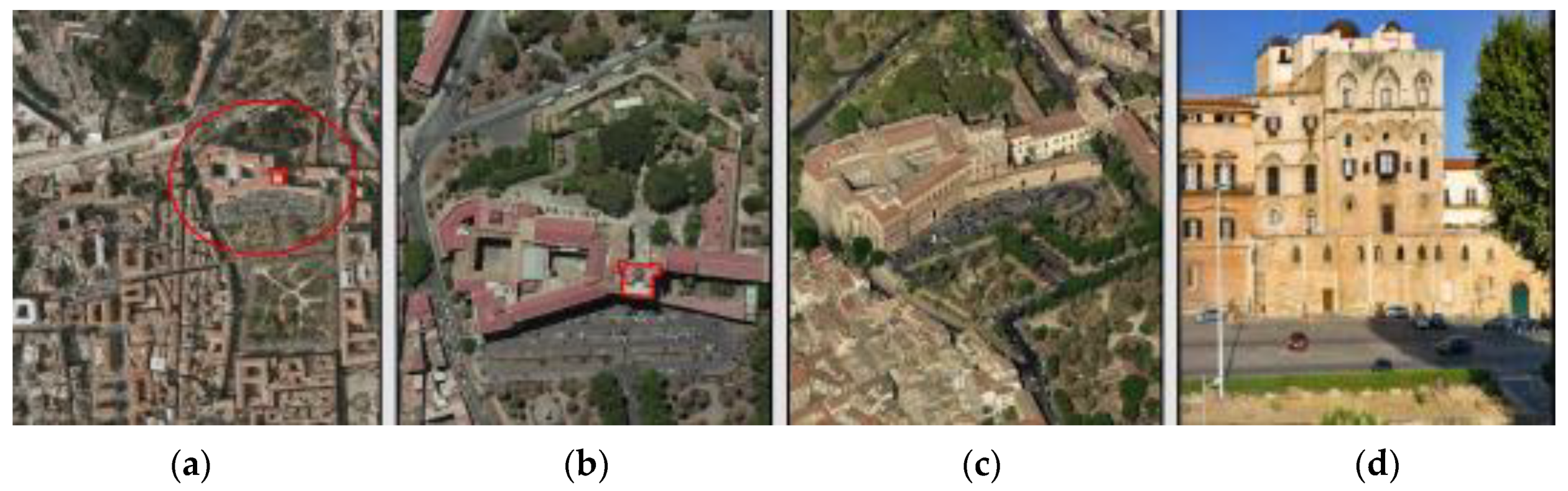
Identification of the construction, that is, its localization in relation to specific risk areas, and the contextualization in the surrounding urban environment. In particular, the morphological analysis of the Tower within the whole Palace and the historical analysis aimed at comprehension of its constructional sequence, and they allowed the complete individuation of the Tower, which is not currently identifiable as such, leading to a non-evident structural configuration. Moreover, concerning the valuable elements (fixed decorative apparatuses, movable artistic goods) that can affect the risk level, the possible sacrifice zones have been individuated in the top levels, which was partially realized in the age of the Spanish Viceroyalty but modified at the end of the 18th century, and partially constructed between the end of the 18th and the middle of the 19th century, at the time of the construction of the Astronomical Observatory.
-
Geometric survey of the construction, intended as the complete stereometric description of the building, including possible damage phenomena, such as cracks, loss of verticality, permanent deformations, etc. The present work used a geometric survey from a previous study in 2012; despite the high level of accuracy, that study did not have the same goals as the present one, which aimed at the identification of the structural layout and the definition of the calculation model to be used in subsequent structural assessments. This required collecting some integrative data; however, many more data—in particular, the structural typologies of masonry walls (monolithic, double, or rubble masonry wall) and the profiles of the vaulted slabs—should be obtained through noninvasive analyses, to protect the listed building.
-
Individuation of the evolution of the building, intended as the sequence of the building’s transformation phases, from the hypothesized original configuration to the current one. The historical analysis required an in-depth study for the comprehension of the modifications to the structural system after the additions of new constructions, as in the period of the Spanish Viceroyalty, or new elevations, as for the Astronomical Observatory, in addition to restoration and reinforcement interventions performed over time.
-
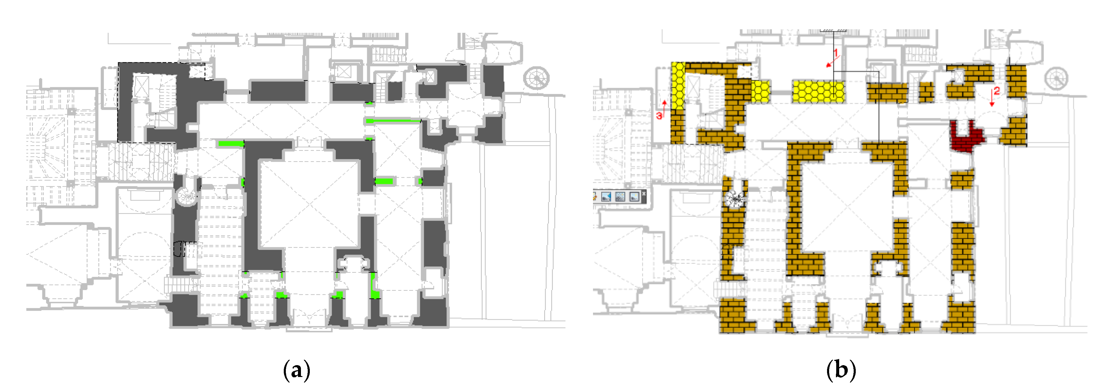
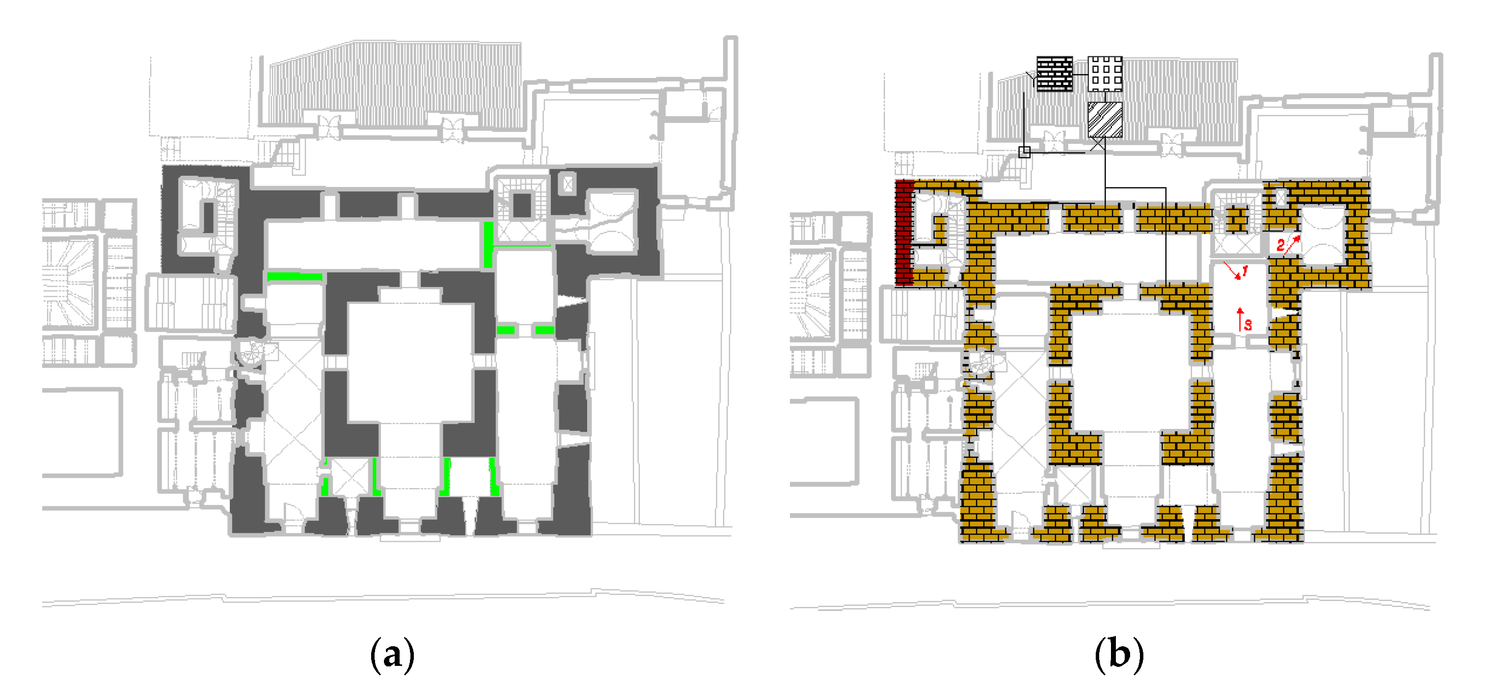
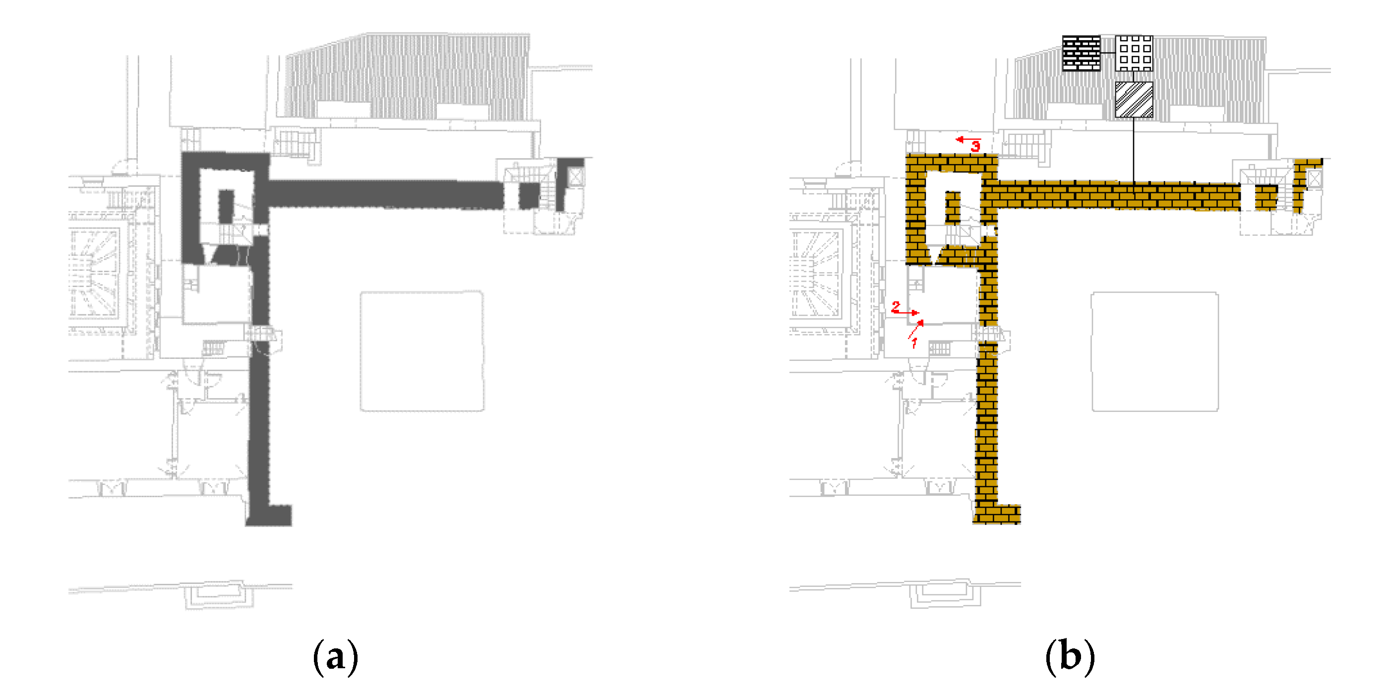
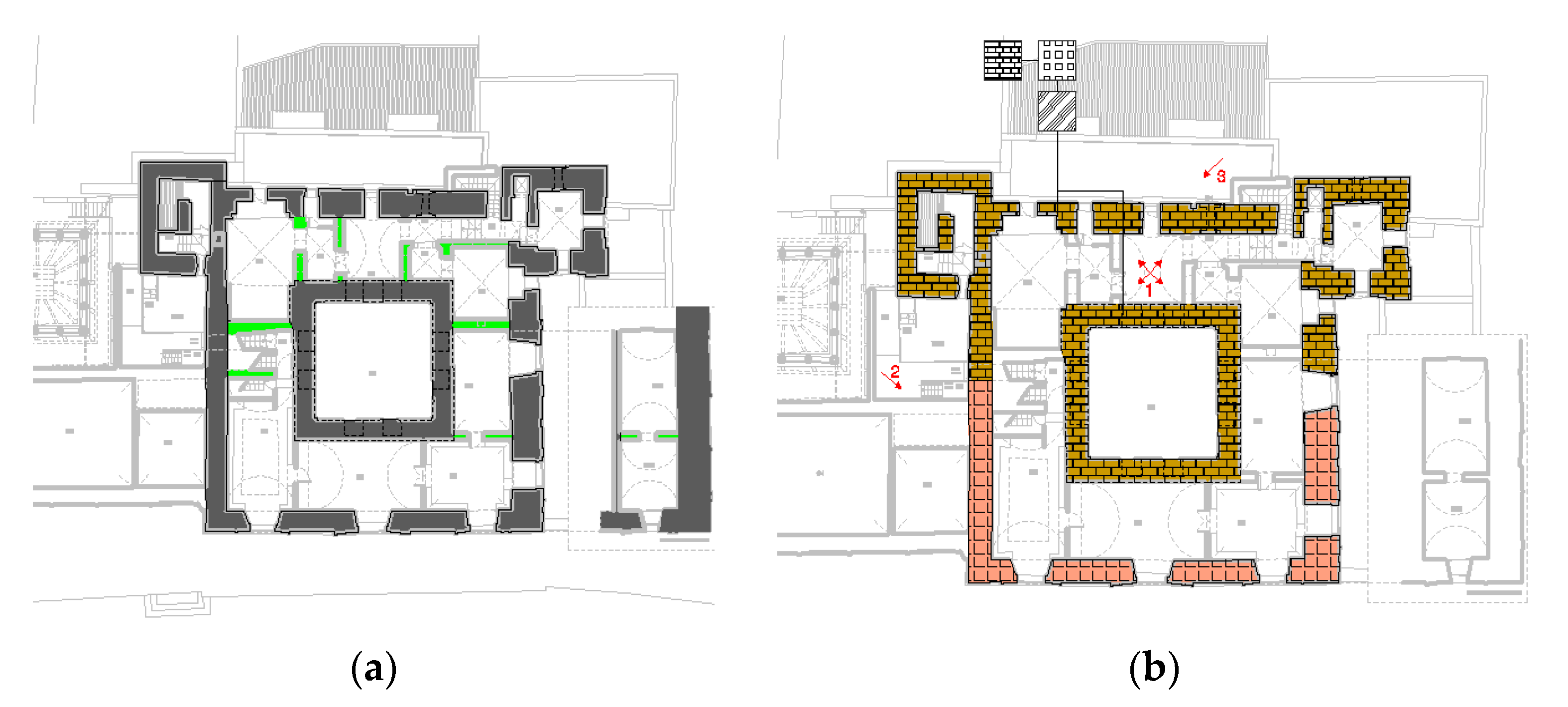
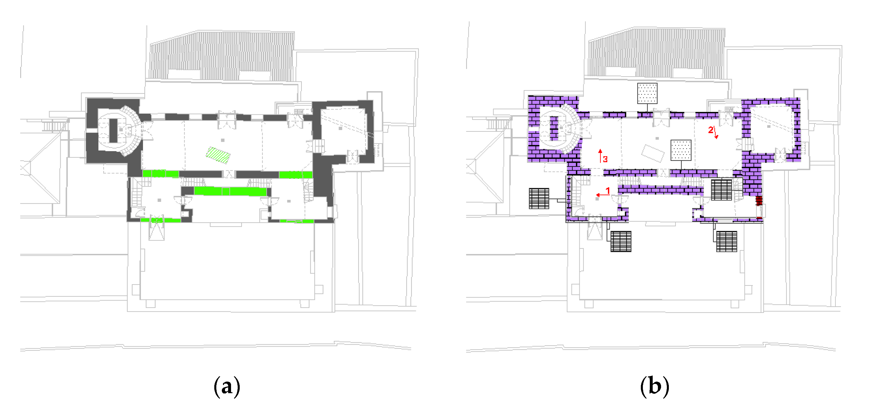
Individuation of the elements of the load-bearing structure, in its material and construction meaning, focusing on construction techniques and details, and connections between elements. This was developed based on some results from the experimental investigations in 2012 and the integrative tests performed in this study, including the examination of historical documentation as well as recent documentation related to the reinforcement intervention performed at the level of the Astronomical Observatory in the 1990s. The load-bearing structure of each level was hypothesized based on the collected information; it was identical at the bottom levels and then changed at the top levels, following demolitions and reconstruction interventions, where more recent floor slab typologies were used.
-
Identification of materials, their decay state, and mechanical properties. The investigation of this aspect, too, involved the use of the surveys carried out in the test campaign in 2012, integrated with the video endoscopic tests carried out in the present study. However, considering the limited number of surveys, the support of historical investigation was required and allowed individuating different typologies associated with different construction ages (masonry of the Norman period, masonry of the period of the Spanish Viceroyalty, and the recent masonry of the Astronomical Observatory). Historical and recent photographic documentation was useful for this purpose. It was then possible to identify the typologies within the tables of Guidelines, which report the most common typologies of masonry; hence, the values for the rigidity, resistance, and unit weight of the materials were inferred.
-
Knowledge of the subsoil and foundation structures, also including the variations over time and related instability phenomena. The lack of specific tests did not allow identifying the depth and typology of foundations; previous studies on the adjacent lots of other parts of the Palace were used for the attribution of physical–mechanical parameters to the soil. There were no visible cracks or damage in the bottom part; the absence of ground instability could thus be inferred. The soil class for the definition of response spectra was classified through specific seismic tests, which led to its identification as soil class C—at the boundary with class B—through the propagation velocity of shear waves.
All these aspects contributed to individuating the confidence factors to use in structural analysis models aimed at assessment of the seismic safety of the building. In particular, the seismic numerical analysis of the Tower represents the next step of this research, aimed at the design of structural interventions for the mitigation of the vulnerabilities. One final suggestion for future work is the adoption of periodic or continuous monitoring, recording in an automated way or otherwise the position of control points located in key areas or areas with a particular vulnerability, to determine their variations (absolute and relative displacements) over time. This would allow verifying variations in the cracking patterns on structural components over time, possibly assessing their criticality and determining their causes. Hence, seismic vulnerability tests should be complemented by a monitoring plan, to allow the control of potential cinematic mechanisms, provide a dynamic characterization of the structure, and validate a numerical model.

Author Contributions

Conceptualization, L.L.M., M.A., F.A. and A.M.; methodology, L.L.M., M.A., F.A. and A.M.; writing, review, and editing, L.L.M., M.A., F.A. and A.M.; funding acquisition, L.L.M. All authors have read and agreed to the published version of the manuscript.

Funding

This research was funded by the Civil Protection Department of Sicily (Italy), grant number 270000D01-P6BD, and the APC was funded by Prof. L. La Mendola, University of Palermo-Italy.

Data Availability Statement

The data presented in this study are available on request from the corresponding author. The data are not publicly available due to the privacy of the data.

Acknowledgments

The authors want to thank Antonio Cottone, the Regional Sicilian Assembly technical staff, and technicians of the Building Authority of the city of Palermo for their helpful discussion and the documentation provided to support this investigation. The authors want to thank the geologist Giacomo Marino for the execution of the single-station passive seismic tests.

Conflicts of Interest

The authors declare no conflict of interest.

References

  1. Zizi, M.; Rouhi, J.; Chisari, C.; Cacace, D.; De Matteis, G. Seismic Vulnerability Assessment for Masonry Churches: An Overview on Existing Methodologies. Buildings 2021, 11, 588. [Google Scholar] [CrossRef]
  2. Ceroni, F.; Casapulla, C.; Cescatti, E.; Follador, V.; Prota, A.; da Porto, F. Damage assessment in one-nave churches and analysis of the most recurring mechanisms after the 2016-2017 Central Italy earthquakes. Bull. Earthq. Eng. 2022, 20, 8031–8059. [Google Scholar] [CrossRef]
  3. Yanık, Y.; Aymelek, A.; Çalık, İ.; Türker, T. Vibration testing and performance evaluation of Hagia Sophia bell tower after recent restoration. Constr. Build Mater. 2022, 347, 128617. [Google Scholar] [CrossRef]
  4. Combey, A.; Mercerat, D.E.; Gueguen, P.; Langlais, M.; Audin, L. Postseismic Survey of a Historic Masonry Tower and Monitoring of Its Dynamic Behavior in the Aftermath of Le Teil Earthquake (Ardèche, France). Bull. Seismol. Soc. Am. 2022, 112, 1101–1119. [Google Scholar] [CrossRef]
  5. Du, H.; Yu, J.; Wang, Y.; Zhu, Y.; Tang, Y.; Wang, H. Visualized Failure Prediction for the Masonry Great Wall. Buildings 2022, 12, 2224. [Google Scholar] [CrossRef]
  6. Simon, J.; Bagi, K. Discrete element analysis of the minimum thickness of oval masonry domes. Int. J. Archit. Herit. 2016, 10, 457–475. [Google Scholar] [CrossRef]
  7. Scamardo, M.; Zucca, M.; Crespi, P.; Longarini, N.; Cattaneo, S. Seismic Vulnerability Evaluation of a Historical Masonry Tower: Comparison between Different Approaches. Appl. Sci. 2022, 12, 11254. [Google Scholar] [CrossRef]
  8. Valente, M. Seismic behavior and damage assessment of two historical fortified masonry palaces with corner towers. Eng. Fail. Anal. 2022, 134, 106003. [Google Scholar] [CrossRef]
  9. Sözen, Ş. Assessment of Seismic Load Capacity of a Slender Masonry Clock Tower. Period. Polytech. Civ. Eng. 2022, 66, 491–501. [Google Scholar] [CrossRef]
  10. Cacace, D.; Chisari, C.; De Matteis, G. Large-Scale Analysis of Masonry Bell Towers in Naples. In Proceedings of the International Conference on Protection of Historical Constructions, Athens, Greece, 25–27 October 2021. [Google Scholar]
  11. Chisari, C.; Cacace, D.; De Matteis, G. A mechanics-based model for simplified seismic vulnerability assessment of masonry bell towers. Eng. Struct. 2022, 270, 114876. [Google Scholar] [CrossRef]
  12. Lemos, J.V. Discrete element modeling of masonry structures. Int. J. Archit. Herit. 2007, 1, 190–213. [Google Scholar] [CrossRef]
  13. Pulatsu, B.; Erdogmus, E.; Lourenço, P.B.; Lemos, J.V.; Tuncay, K. Simulation of the in-plane structural behavior of unreinforced masonry walls and buildings using DEM. Structures 2020, 27, 2274–2287. [Google Scholar] [CrossRef]
  14. Martínez, J.; Ávila, F.; Puertas, E.; Burgos, A.; Gallego, R. Historical and architectural study for the numerical modeling of heritage buildings: The Tower of Comares of the Alhambra (Granada, Spain). Inf. Constr. 2022, 74, e429. [Google Scholar] [CrossRef]
  15. Maniaci, A. Palermo Capitale Normanna: Il Restauro Tra Memoria e Nostalgia Dall’ottocento al Piano Particolareggiato Esecutivo; Flaccovio Ed.: Palermo, Italy, 1994; pp. 1–182. [Google Scholar]
  16. La Duca, R. Il Palazzo dei Normanni; Flaccovio Ed.: Palermo, Italy, 1997; pp. pp. 1–184. [Google Scholar]
  17. Foderà Serio, G.; Chinnici, I. L’Osservatorio Astronomico di Palermo; Flaccovio Ed.: Palermo, Italy, 1997; pp. 1–184. [Google Scholar]
  18. Di Fede, M.S. Il Palazzo Reale di Palermo tra il XVI e XVII Secolo; Caracol Ed.: Palermo, Italy, 2000; pp. pp. 1–176. [Google Scholar]
  19. Directive of the Chairman of the Council of Ministers. Guidelines for the Assessment and Mitigation of the Seismic Risk of the Cultural Heritage—Referred to the Technical Rules for Constructions. Official Gazette of the Italian Republic n. 47, 26th February 2011. (In Italian)
  20. Valenti, F. L’arte Nell’era Normanna, in “Il Regno Normanno”; Istituto Nazionale Fascista di Cultura, sezione di Palermo (a cura di): Messina, Italy, 1925. [Google Scholar]
  21. Piazzi, G. Della Specola Astronomica de Regi Studi di Palermo; Reale Stamperia: Rome, Italy, 1826. [Google Scholar]
  22. Todaro, P. Il rischio sismico nel centro storico di Palermo: Rigidità sismica e modelli geologici semplificati per terreni di sedime di fondazioni datate. In Archeometria del Costruito. L’edificato storico: Materiali, Strutture e Rischio Sismico; Edipuglia s.r.l.: Bari, Italy, 2006. [Google Scholar]
  23. Directive of the Chairman of the Council of Ministers. Italian Building Code NTC2018—D.M. 17.01.2018, Official Gazette of the Italian Republic n. 42, 20th February 2018. (In Italian)
  24. Superior Council of Public Works. Instructions for the Application of “New Italian Building Code NTC 2018”. Circular n. 7, 21st January 2019. (In Italian)
  25. Tassios, T.P. The Mechanics of Masonry; Symmetria Publishing: Athens, Greece, 1987. [Google Scholar]
  26. Todaro, P. Il sottosuolo di Palermo. In Archeometria del Costruito. L’edificato Storico: Materiali, Strutture e Rischio Sismico; Flaccovio Ed.: Palermo, Italy, 1988. [Google Scholar]
  27. Todaro, P. Palermo Geologia del Centro Storico. In Atlante Geologico-Stratigrafico, 1st ed; Flaccovio Ed.: Palermo, Italy, 1995. [Google Scholar]
Figure 1. Photos of the Royal Palace: (a) general view; (b) planimetric indication of the Pisan Tower; (c) view from the east side; (d) main front (east) of the building.
Heritage 06 00306 g001
Figure 2. Planimetry of the Royal Palace, with the Pisan Tower colored in red.
Heritage 06 00306 g002
Figure 3. Rooms of high artistic value inside the Pisan Tower and in adjacent spaces.
Heritage 06 00306 g003
Figure 5. Representations of the Royal Palace in the Norman age: (a) reconstruction of the floor plan by F. Valenti [20]; (b,c) reconstruction of the elevations according to F. Valenti, drawn by P. Lo Jacono and R. Longo.
Heritage 06 00306 g005
Figure 6. (a) Axonometric view of the original configuration according to V. Zorić; (b) interior view of the central core (President’s Room) with the paired ogival openings that nowadays face interior rooms; (c) photograph of the main prospect (east) of the external frame of the Tower.
Heritage 06 00306 g006
Figure 7. Various images depicting the Tower in the 17th century with the pavilion roof.
Heritage 06 00306 g007
Figure 8. Conceptual reconstruction of the current floor of the Piazzi Library in the age of the Spanish Viceroyalty.
Heritage 06 00306 g008
Figure 9. Gallery of the Astronomical Observatory: (a) drawing by Giuseppe Piazzi; (b) reconstruction of the original layout of the gallery, with a dashed square showing the central core of the Tower.
Heritage 06 00306 g009
Figure 10. (a) Ideal reconstruction of the floor of the Observatory in 1795, at the time of the realization of the two porches; (b) reconstruction of the modifications in 1795, when the two turrets were joined, and in 1865, when the large cupola was raised; (c) view of the east side of the upper part of the Tower, with indication of the central core.
Heritage 06 00306 g010
Figure 11. Details of the execution of the Boscarino–Cottone intervention (1990s): (a,b) photos related to the floor slab of the room on the left of the gallery, showing the diagonal crossbeam and the electro-welded mesh above hollow blocks; (c) reinforcement of the central vault for the sustainment of the steel reticular column which supports Mertz’s equatorial telescope.
Heritage 06 00306 g011
Figure 12. Identification of the structural system (from the technical drawings of the Officina per le Arti Opera company): (a) denomination of the various levels of the Pisan Tower; (b) axonometric sectional view at level C; (c) axonometric sectional view at levels D-E; (d) axonometric sectional view at level H; (e) axonometric general view of the Tower.
Heritage 06 00306 g012
Figure 13. Results of endoscopic surveys S102, S111, and S112.
Heritage 06 00306 g013
Figure 14. Crack patterns (in red) and steel ties (in blue) (from the drawings of the Officina per le Arti Opera company): (a) on the north side; (b) on the east side; (c) on the floor plan at the height of 13.00 m; (d) on the floor plan at the height of 28.70 m.
Heritage 06 00306 g014
Figure 15. Identification of the structure of the Tower on level A (height 2.90 m); (a) hypothesized vertical load-bearing structure; (b) hypothesized materials.
Heritage 06 00306 g015
Figure 16. Identification of the structure of the Tower on level B (height 8.40 m): (a) hypothesized vertical load-bearing structure; (b) hypothesized materials.
Heritage 06 00306 g016
Figure 17. Identification of the structure of the Tower on level C (height 13.00 m): (a) hypothesized vertical load-bearing structure; (b) hypothesized materials.
Heritage 06 00306 g017
Figure 18. Identification of the structure of the Tower on levels D-E (height 19.60 m): (a) hypothesized vertical load-bearing structure; (b) hypothesized materials.
Heritage 06 00306 g018
Figure 19. Identification of the structure of the Tower on level F (height 23.60 m): (a) hypothesized vertical load-bearing structure; (b) hypothesized materials.
Heritage 06 00306 g019
Figure 20. Identification of the structure of the Tower on level G (height 27.00 m): (a) hypothesized vertical load-bearing structure; (b) hypothesized materials.
Heritage 06 00306 g020
Figure 21. Identification of the structure of the Tower on level H (height 28.70 m): (a) hypothesized vertical load-bearing structure; (b) hypothesized materials.
Heritage 06 00306 g021
Figure 22. Identification of the structure of the Tower on level L (height 37.70 m): (a) hypothesized vertical load-bearing structure; (b) hypothesized materials.
Heritage 06 00306 g022
Figure 24. Influence of the joint width/ashlar height on the compression strength of masonry [15].
Heritage 06 00306 g024
Figure 25. Typical geological cross-section [26].
Heritage 06 00306 g025
Figure 26. Geological map of the site [26].
Heritage 06 00306 g026
Figure 27. Planimetry with the location of the surveys.
Heritage 06 00306 g027
Figure 28. Results of single-station passive seismic tests.
Heritage 06 00306 g028
Figure 29. Axonometric views of the theoretical local collapse mechanisms: (ac) rotation of the north wall at different levels; (d) rotation of the east wall; (e) rotation of the north-east corner area; (f) most probable simple overturning of the north wall (angle γ = 0) and a portion of masonry in the east wall.
Heritage 06 00306 g029
Table 1. Extract of Table C8.5.I of the Circular of NTC2018 [23,24].
Masonry Typologyfm
[N/mm2]
Min-Max
τ0
[N/mm2]
Min-Max
E
[N/mm2]
Min-Max
G
[N/mm2]
Min-Max
w
[kN/m3]
Masonry in quarry stones with a good texture2.6
3.8
0.056
0.074
1500
1980
500
660
21
Masonry in soft stone ashlars (tuff, calcarenite, etc.)1.4
2.2
0.028
0.042
900
1260
300
420
13 ÷ 16
Masonry in full bricks and lime mortar2.6
4.3
0.05
0.13
1200
1800
400
600
18
Table 2. Corrective coefficients extracted from Table C8.5.II of the Circular of NTC2018 [23,24].
Masonry TypologyGood Mortar QualityDouble Courses and TrimmingTransversal ConnectionMortar InjectionsReinforced Plaster Injections
Masonry in quarry stones with a good texture1.31.11.31.51.5
Masonry in soft stone ashlars (tuff, calcarenite, etc.)1.51.21.31.41.7
Masonry in full bricks and lime mortarfm0.35 *-1.31.21.5
* with fm the average compressive strength of mortar expressed in N/mm2.
Table 3. Mechanical properties of the introduced masonry typologies.
Masonry Typologyfm
(N/mm2)
τ0
(N/mm2)
E
(N/mm2)
G
(N/mm2)
w
(kN/m3)
Masonry in quarry stones with a good texture3.20.065174055021
Masonry in soft stone ashlars (tuff, calcarenite, etc.)—Norman Period3.070.13074123017
Masonry in soft stone ashlars (tuff, calcarenite, etc.)—Period of the Spanish Viceroyalty1.190.0238172068816
Masonry in soft stone ashlars (tuff, calcarenite, etc.)—Period of the 19th century—Astronomical Observatory1.900.035126036016
Masonry in full bricks and lime mortar3.200.076150050018
Table 4. Values of the Fck terms.
Geometric surveyFC1 = 0.05The survey was performed on the whole building with a laser scanner. However, it was not possible to detect the geometry of all vertical and horizontal structural components at all levels. Hence, the highest value of the confidence factor was chosen.
Identification of the specific historical and constructional characteristics of the buildingFC2 = 0.12A reconstruction of the construction phases has been hypothesized, on the base of a limited survey of materials and construction elements, associated with the comprehension of the sequence of transformations (documental and thematic investigations).
Mechanical propertiesFC3 = 0.12The mechanical parameters have been obtained from available data, with reference to the tables indicated by the Circular of NTC2018 [24]. Tests and/or investigations were only partially possible, limited to some masonry typologies; moreover, the number was scarce in relation to the variability of mechanical parameters, that is intrinsic to masonry.
Soil and foundationsFC4 = 0.06The performed tests and available data allowed correct identification of the typology of the soil below the Pisan Tower and its geotechnical properties.
Disclaimer/Publisher’s Note: The statements, opinions and data contained in all publications are solely those of the individual author(s) and contributor(s) and not of MDPI and/or the editor(s). MDPI and/or the editor(s) disclaim responsibility for any injury to people or property resulting from any ideas, methods, instructions or products referred to in the content.

