
The Complex Architecture of the Vault System of an Early Medieval Church


Abstract
1. Introduction
2. Brief Details about the Church
2.1. Historical Overview
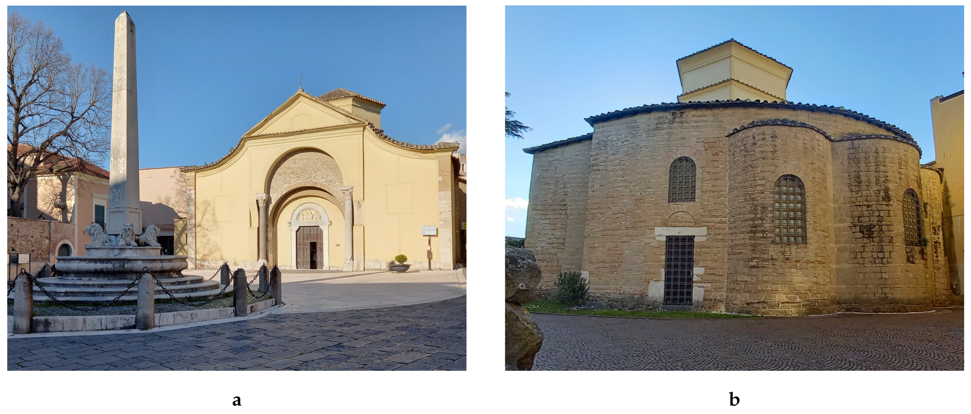
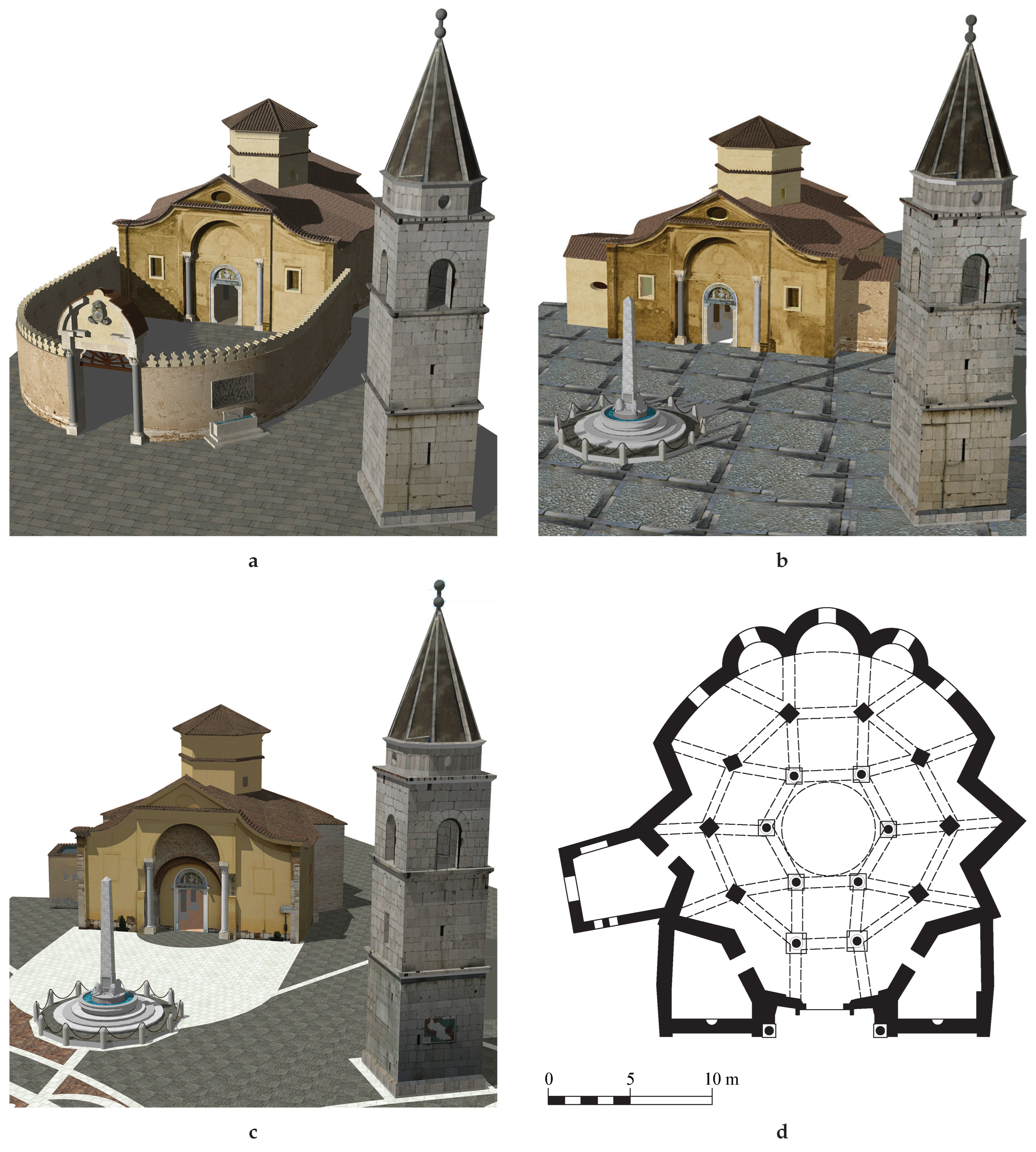
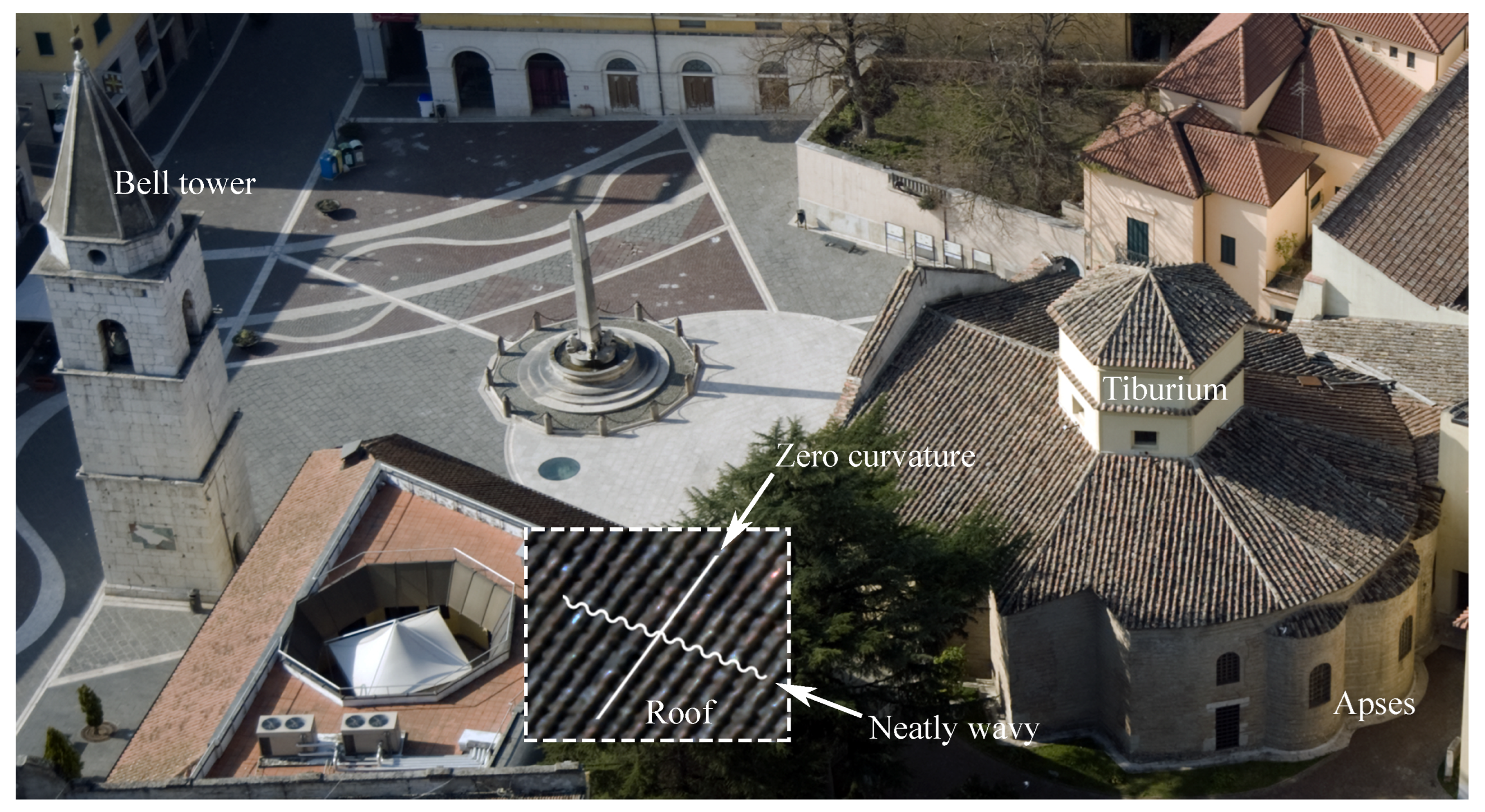
2.2. The Architecture of the Church in Its Current Configuration
3. Materials and Methods
- The search and analysis of sources, usually divided into
- (a)
- archeological,
- (b)
- archival,
- (c)
- bibliographic,
- (d)
- epigraphical,
- (e)
- photographic;
- The formulation of a reconstruction hypothesis on the lost parts;
- The survey of the current layout or of the existing parts;
- The reconstruction of the various phases in a backward fashion from the current layout to the earliest one.
3.1. Archeological Evidences
3.2. Archival, Bibliographic, Epigraphical and Photographic Sources
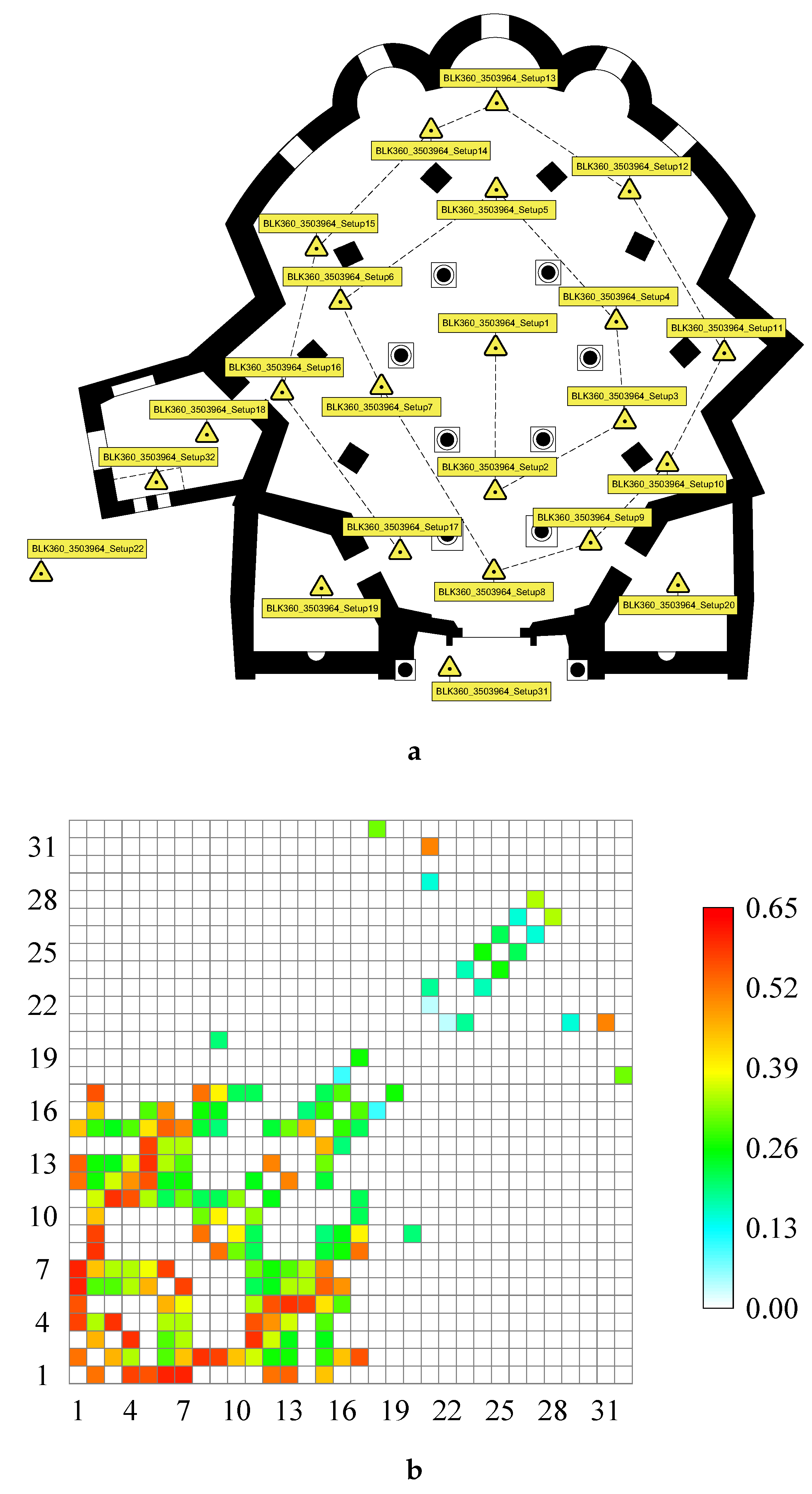
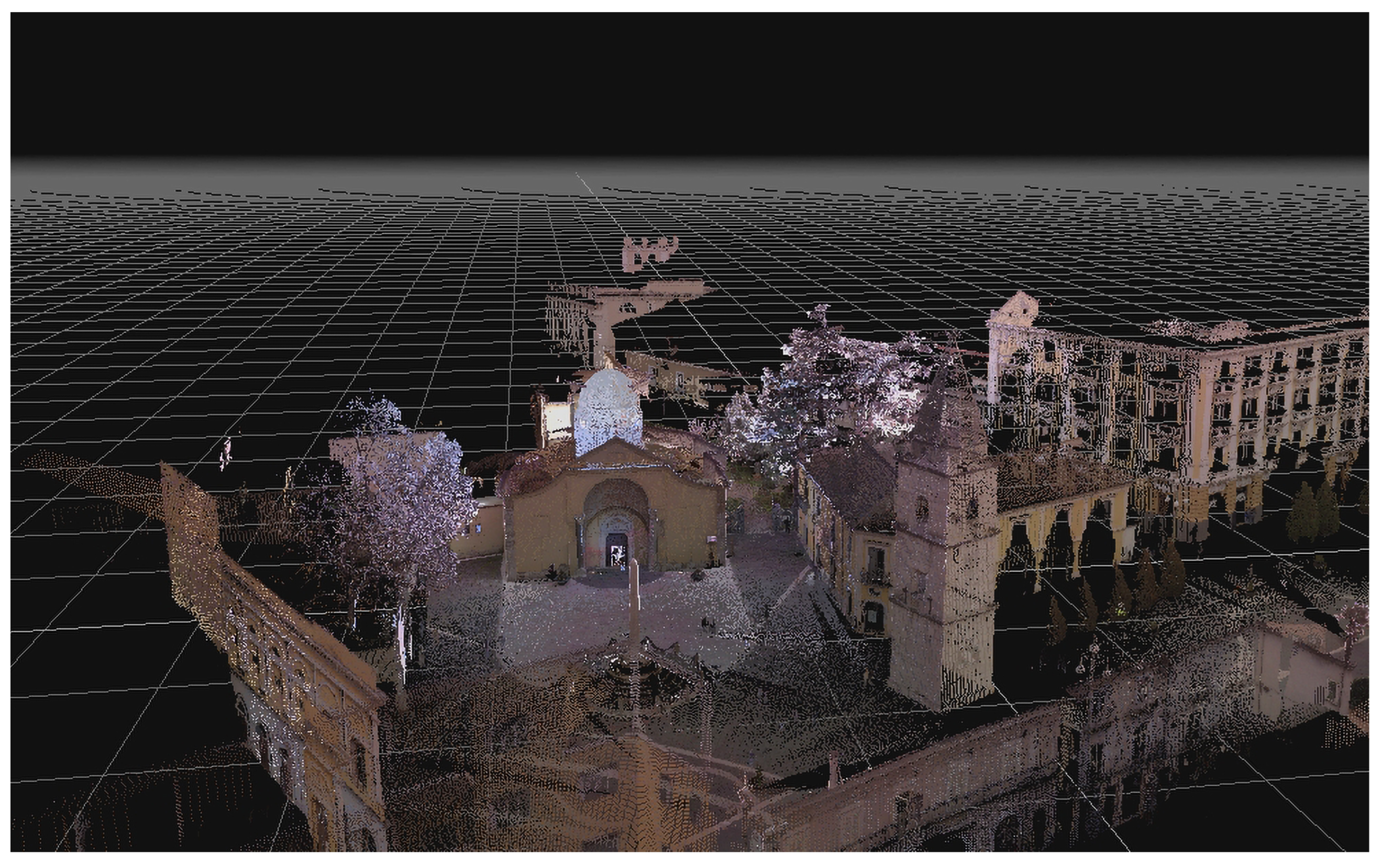
3.3. Digital Survey
3.4. Solid Modeling
4. Approximation and Reconstruction of Vaults
4.1. Workflow of the Reconstruction of the System of Vaults
- With 3DF Zephyr Free, the parts of the bundle point cloud containing only the vaults were selected;
- Data were exported on an ASCII dat file as 22 lists, one for each vault, containing 3D vectors (the coordinates of points);
- The dat file was loaded into Mathematica to compute the approximating surfaces;
- The resulting vaults were exported in a DXFTM file;
- The file was inserted in the 3D models with AutoCAD®.
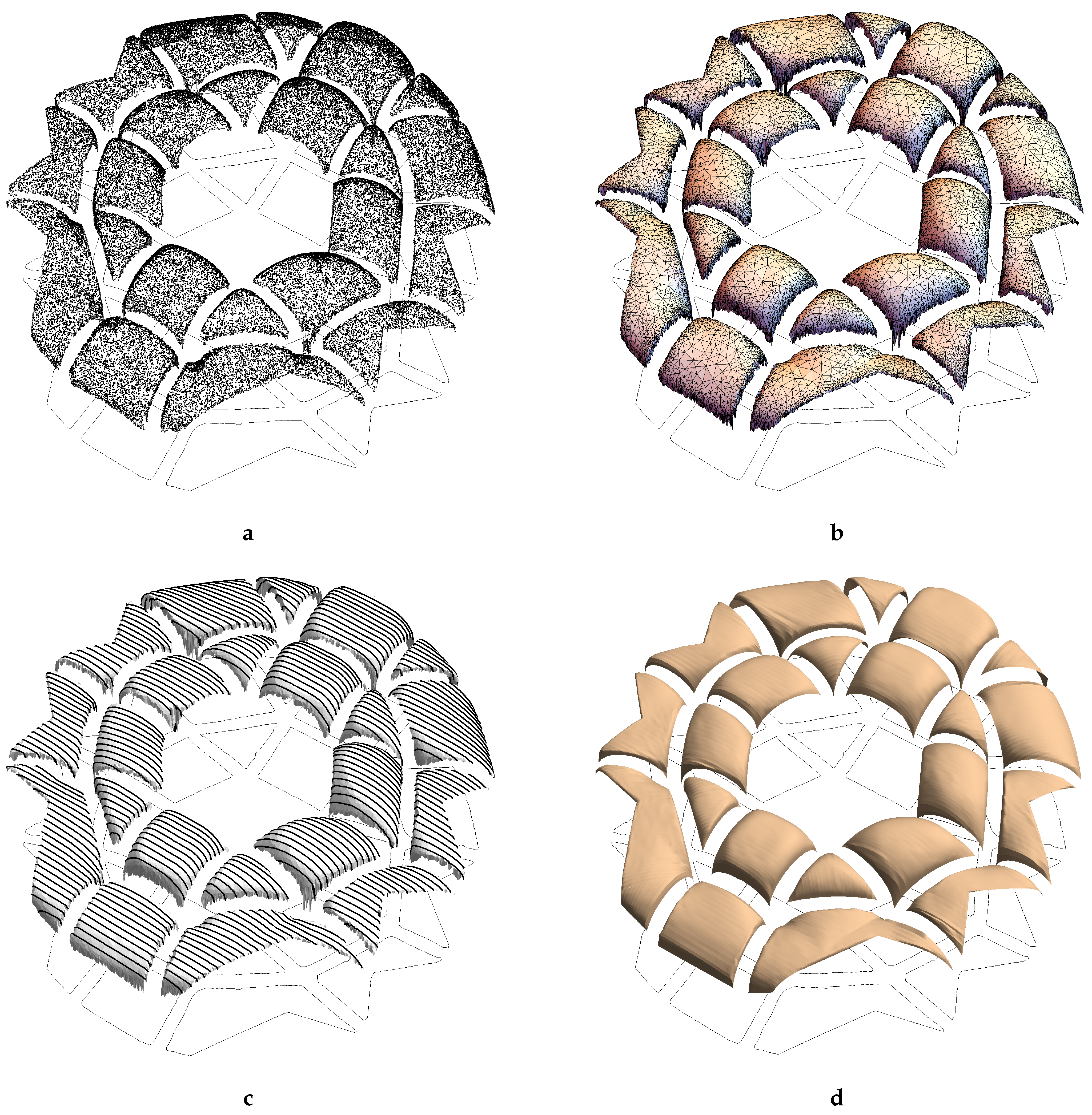
4.2. Surface Approximation
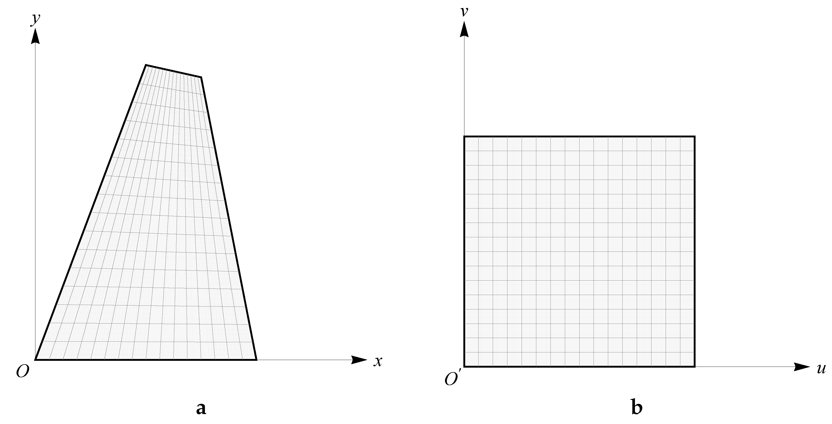
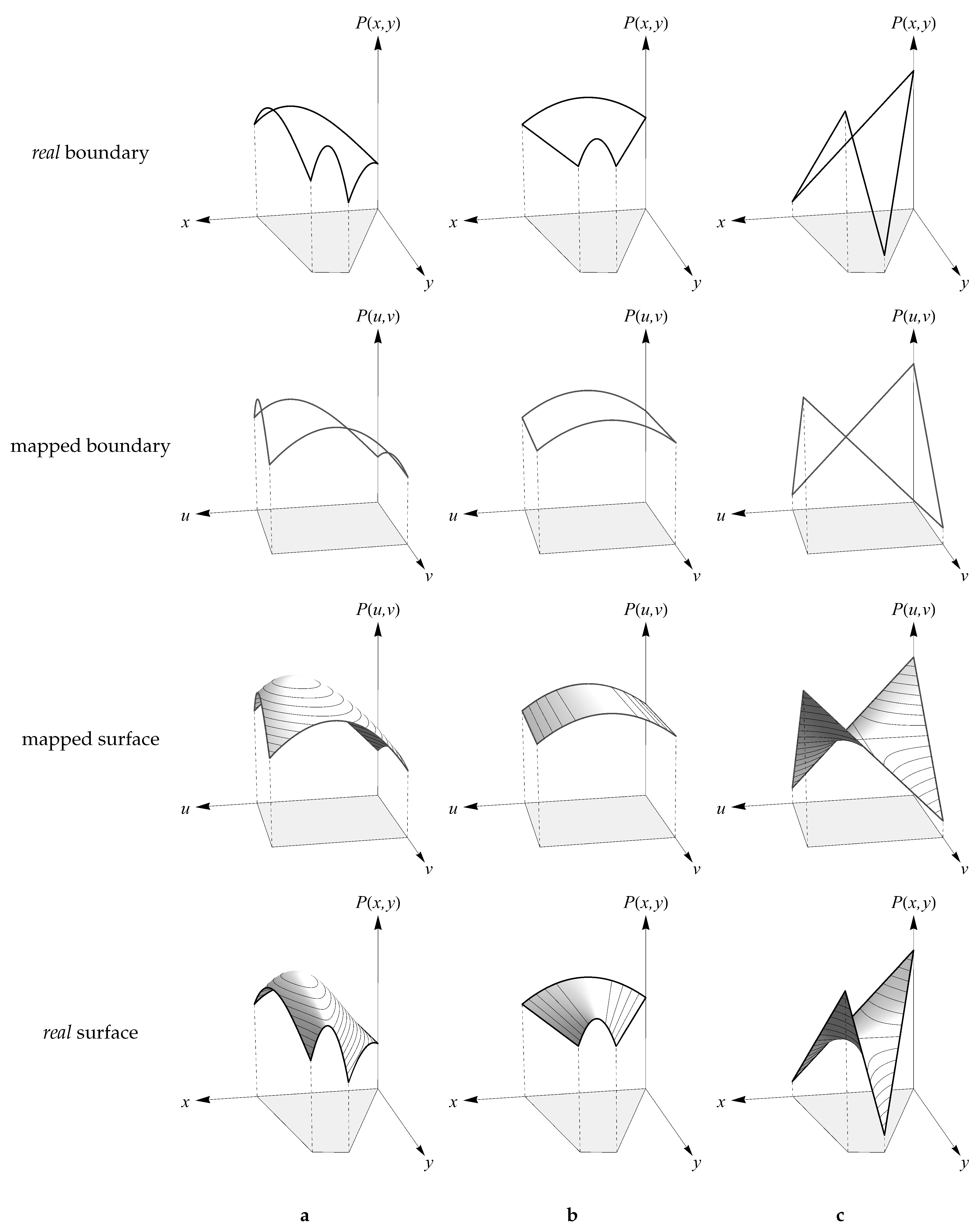
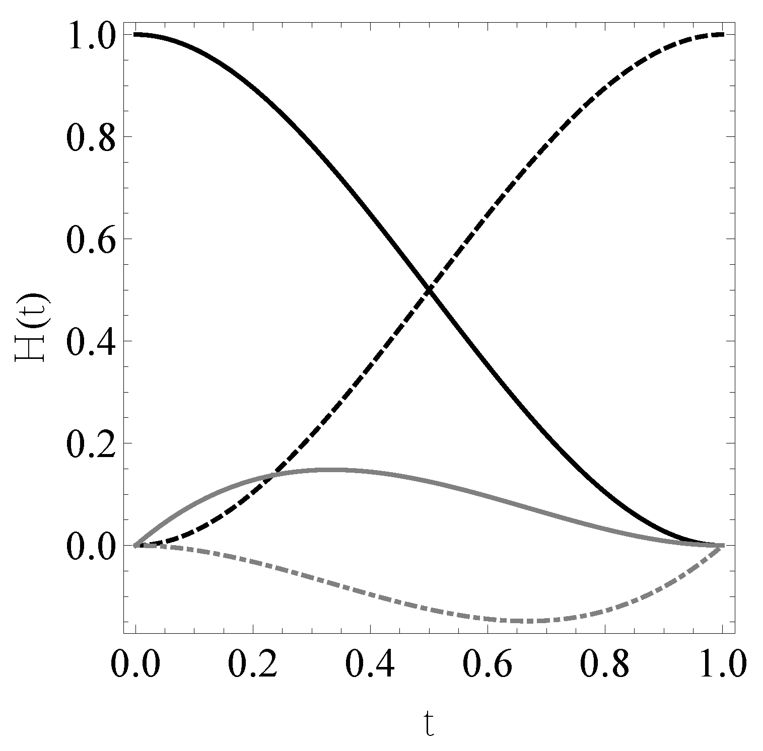
4.3. Patch Construction on the Unit Square Domain
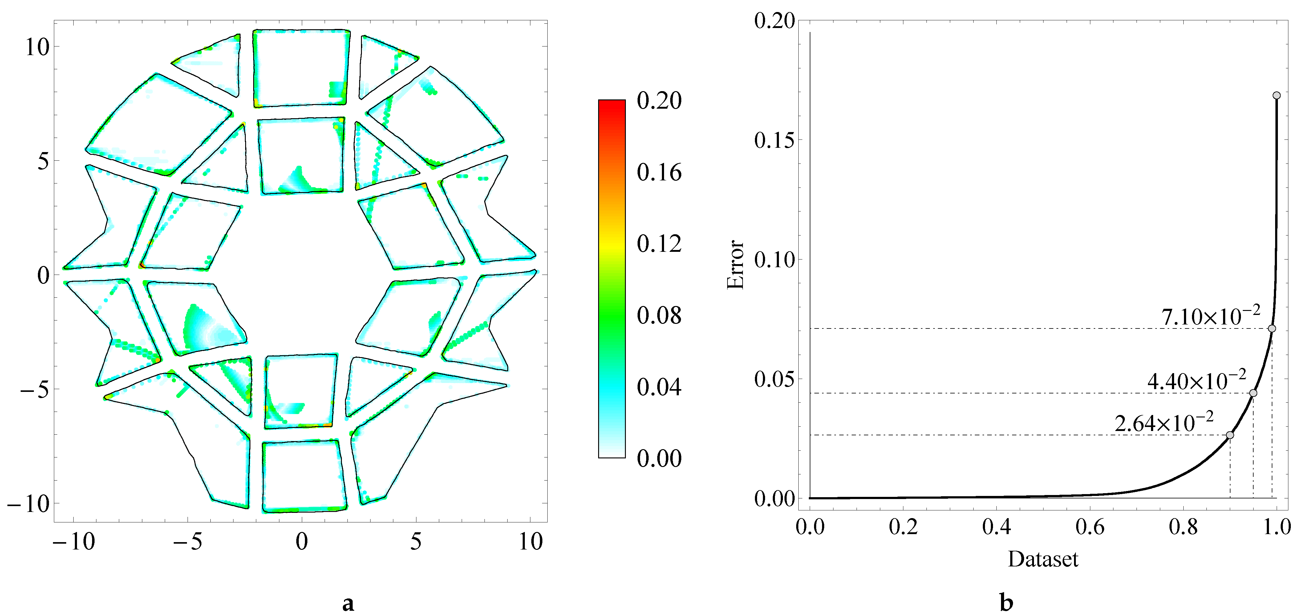
4.4. Error Estimate
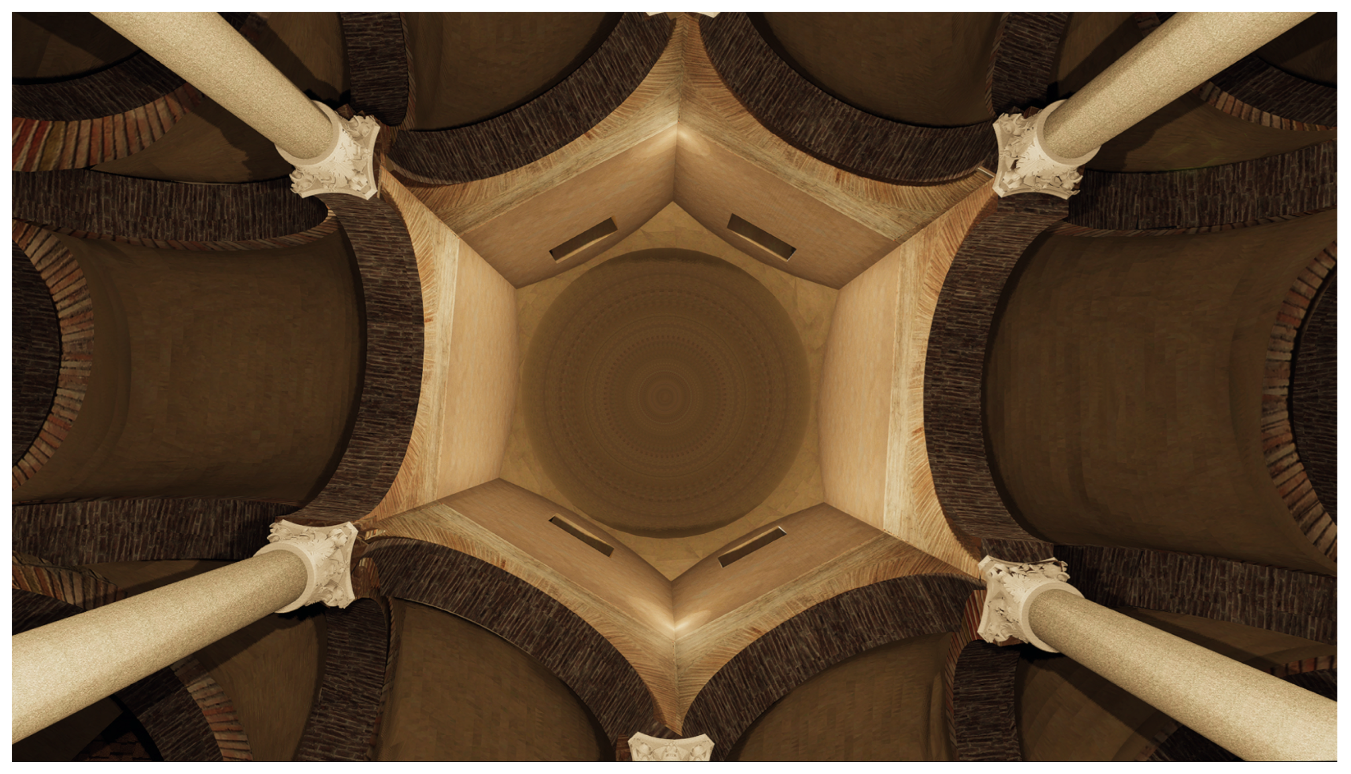
5. Results
Some Remarks about the Approach
6. Conclusions
Author Contributions
Funding
Data Availability Statement
Acknowledgments
Conflicts of Interest
Appendix A. SketchUp UV Mapping
- Select the model to apply a texture on;
- Select Position Texture, allowing to manually position and scale the texture on the surface of the model;
- Select Apply button to map the texture onto the model.
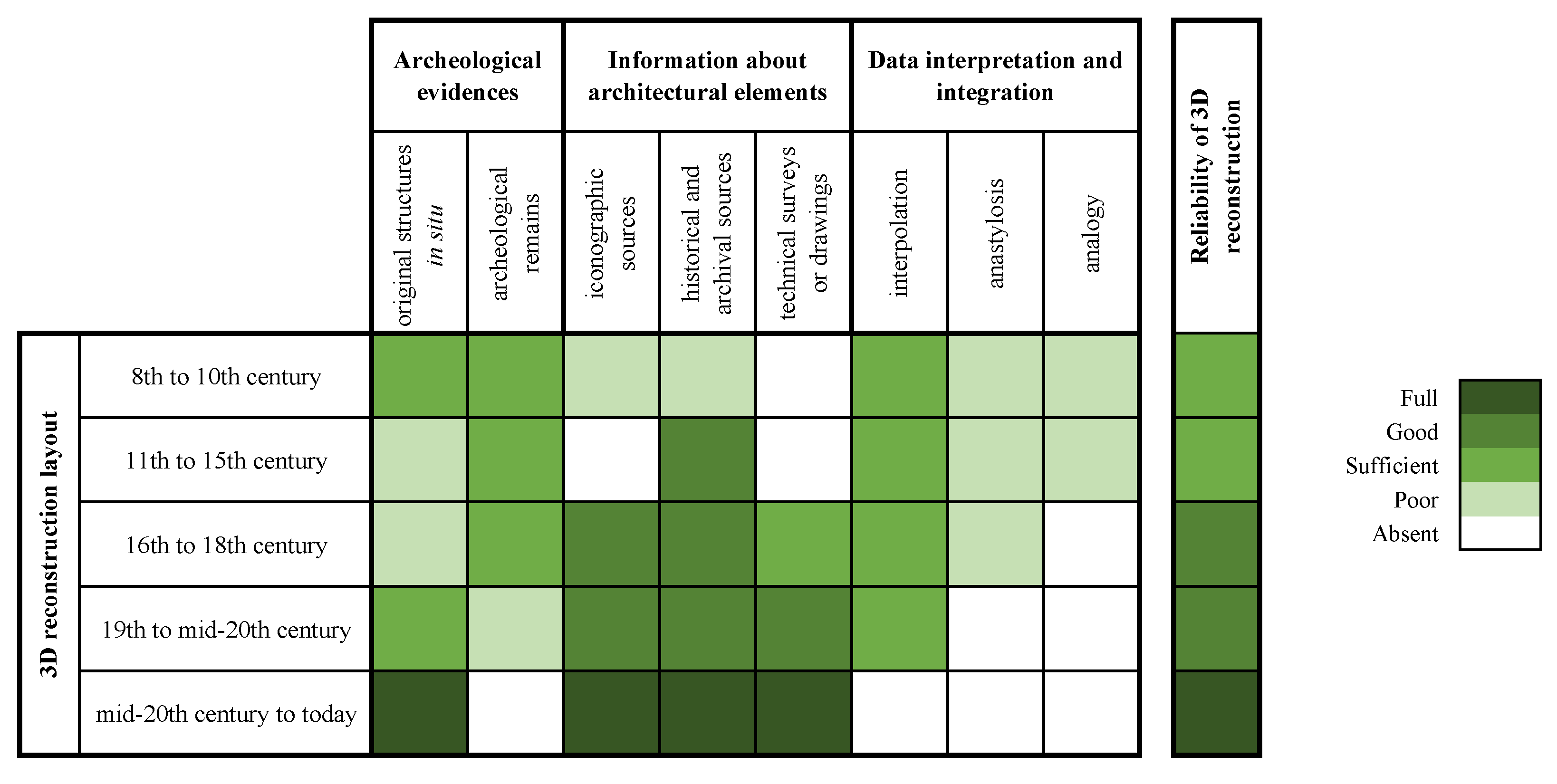
Appendix B. Reliability of 3D Reconstructions

- Interpolation: A process similar to gap filling, which allows two distant elements to be reconnected through an “interpolation”;
- Anastylosis, which consists of recomposing the parts of a monument using software in which the surveyed elements, preferably in 3D, have to be repositioned in their original location;
- Analogy, which allows an apparatus that is coherent with the studied object to be reconstructed, in terms of architectural and stylistic language, through similarity matches between the attested and documented elements.
References
- Pfarr-Harfst, M.; Grellert, M. The reconstruction—Argumentation method. In Proceedings of the Digital Heritage. Progress in Cultural Heritage: Documentation, Preservation, and Protection, Nicosia, Cyprus, 31 October–5 November 2016; Ioannides, M., Fink, E., Moropoulou, A., Hagedorn-Saupe, M., Fresa, A., Liestøl, G., Rajcic, V., Grussenmeyer, P., Eds.; Springer International Publishing: Cham, Switzerland, 2016; pp. 39–49. [Google Scholar]
- Antuono, G.; Cundari, M.R.; Cundari, G.C.; Bagordo, G.M. Survey, data analysis and modeling Raphael’s Stables in Villa Farnesina, Rome. Heritage 2023, 6, 4243–4262. [Google Scholar] [CrossRef]
- Pietroni, E.; Ferdani, D. Virtual restoration and virtual reconstruction in Cultural Heritage: Terminology, methodologies, visual representation techniques and cognitive models. Information 2021, 12, 167. [Google Scholar] [CrossRef]
- Rotili, M. Benevento Romana e Longobarda. L’immagine Urbana; Banca Sannitica: Napoli, Italy, 1986. [Google Scholar]
- Rotili, M. La chiesa di Santa Sofia a Benevento. In Benevento. Le Chiese del Fondo Edifici di Culto del Sannio; Edizioni L’Orbicolare: Milano, Italy, 2011; pp. 27–48. [Google Scholar]
- Rotili, M. Arechi II e Benevento. In Tra i Longobardi del Sud; Rotili, M., Ed.; Il Poligrafo: Padova, Italy, 2017; pp. 181–226. [Google Scholar]
- Rotili, M. Benevento, chiesa di Santa Sofia. Le vicende storiche e architettoniche. In Sulla Pittura Beneventana, Aggiornamento Scientifico; Bertelli, G., Mignozzi, M., Eds.; Mario Adda Editore: Bari, Italy, 2021; pp. 79–82. [Google Scholar]
- Arrighetti, A.; Pansini, R. Introduction [Introduzione]. Archeol. e Calc. 2022, 33, 9–14. [Google Scholar] [CrossRef]
- Gabellone, F. Archeologia Virtuale: Teoria, Tecniche e Casi di Studio; Edizioni Grifo: Lecce, Italy, 2019. [Google Scholar]
- Rotili, M.; Rapuano, S. Le ricerche nel castello e nell’area murata del Monte (1980–1992; 2005–2007): Divulgazione e valorizzazione. In Archeologia Pubblica, Paesaggi e Culture, e Innovazione Sociale. Alcuni Casi di Studio in Campania e Molise. Studi in Onore di Giuseppina Bisogno e in Ricordo di Carmine Diglio; Senatore, A., Mancini, R., Albini, A., Scaduto, M.L., De Tommasi, A., Eds.; All’Insegna del Giglio: Sesto Fiorentino, Italy, 2022; pp. 69–82. [Google Scholar]
- Fassi, F. 3D modeling of complex architecture integrating different techniques—A critical overview. Int. Arch. Photogramm. Remote Sens. Spat. Inf. Sci. 2007, XXXVI-5/W47, 1–11. [Google Scholar]
- Iannizzaro, V.; Barba, S.; Messina, B.; D’Agostino, P.; Fiorillo, F. The domes of the Amalfi Coast: Survey and digital representation of complex shapes. In Proceedings of the International Congress Domes in the World. Symbolism and Cultural Identity, Geometric and Formal Genesis, Construction, Identification, Conservation, Florence, Italy, 19–23 March 2012; Tampone, G., Corazzi, R., Mandelli, E., Eds.; Nardini Editore: Florence, Italy, 2012; pp. 1–12. [Google Scholar]
- Capone, M.; Campi, M.; Catuogno, R. Gothic churches in Paris St Gervais et St Protais image matching 3D reconstruction to understand the vaults system geometry. Int. Arch. Photogramm. Remote Sens. Spat. Inf. Sci. 2015, XL-5/W4, 423–430. [Google Scholar] [CrossRef]
- Bevilacqua, M.G.; Caroti, G.; Martínez-Espejo Zaragoza, I.; Piemonte, A. Frescoed vaults: Accuracy controlled simplified methodology for planar development of three-dimensional textured models. Remote Sens. 2016, 8, 239. [Google Scholar] [CrossRef]
- Brumana, R.; Condoleo, P.; Grimoldi, A.; Banfi, F.; Landi, A.G.; Previtali, M. HR LOD based HBIM to detect influences on geometry and shape by stereotomic construction techniques of brick vaults. Appl. Geomat. 2018, 10, 529–543. [Google Scholar] [CrossRef]
- Murphy, M.; McGovern, E.; Pavia, S. Historic building information modelling (HBIM). Struct. Surv. 2009, 27, 311–327. [Google Scholar] [CrossRef]
- Lanzara, E.; Samper, A.; Herrera, B. Point cloud segmentation and filtering to verify the geometric genesis of simple and composed vaults. Int. Arch. Photogramm. Remote Sens. Spat. Inf. Sci. 2019, XLII-2/W15, 645–652. [Google Scholar] [CrossRef]
- Angjeliu, G.; Cardani, G.; Coronelli, D. A parametric model for ribbed masonry vaults. Autom. Constr. 2019, 105, 102785. [Google Scholar] [CrossRef]
- Farin, G. Curves and Surfaces for CAGD: A Practical Guide; Computer Graphics and Geometric Modeling; Elsevier Science: Amsterdam, The Netherlands, 2002. [Google Scholar]
- Fregonese, L.; Adami, A. The 3D model of St. Mark’s Basilica in Venice. In Digital Transformation of the Design, Construction and Management Processes of the Built Environment; Daniotti, B., Gianinetto, M., Della Torre, S., Eds.; Springer International Publishing: Cham, Switzerland, 2020; pp. 343–354. [Google Scholar] [CrossRef]
- Spallone, R.; López González, M.C.; Vitali, M.; Bertola, G.; Natta, F.; Ronco, F. Recognizing the design patterns of complex vaults: Drawing, survey and modeling. Experiments on Palazzo Mazzonis’ atrium in Turin. In Proceedings of the Digital Heritage. Progress in Cultural Heritage: Documentation, Preservation, and Protection, Virtual, 2–5 November 2020; Ioannides, M., Fink, E., Cantoni, L., Champion, E., Eds.; Springer International Publishing: Cham, Switzerland, 2021; pp. 3–14. [Google Scholar]
- Incerti, M. Dal rilievo all’analisi di superfici complesse: il caso della pseudo-cupola di Galla Placidia. Archeol. Calc. 2022, 33, 55–72. [Google Scholar] [CrossRef]
- Capone, M.; Palomba, D.; Scandurra, S.; Lanzara, E. Trapezoidal and apsidal ribbed vaults smart 3D reconstruction. Int. Arch. Photogramm. Remote Sens. Spat. Inf. Sci. 2022, XLVI-2/W1-2022, 135–142. [Google Scholar] [CrossRef]
- Jobbik, E.; Krähling, J. A self-contained stellar vault construction method. The vault of the Matthias Oratorio in the Inner City Parish Church of Budapest. Period. Polytech. Archit. 2023, 54, 73–85. [Google Scholar] [CrossRef]
- Jobbik, E.; Krähling, J. A cross-vault system’s relative periodisation based on geometric analysis: The vaulting system of the apse of the Inner City Parish Church of Budapest. Építés-Építészettudomány 2023, 51, 115–137. [Google Scholar] [CrossRef]
- Wolfram Research, Inc. Mathematica, Version 8.0; Wolfram Research, Inc.: Champaign, IL, USA, 2010. [Google Scholar]
- Complectens monumenta varia spectantia ad ecclesiam, monasterium et monachos Sanctae Sophiae, Volumen III. Ancient manuscript document. Currently housed in the Archivio Storico Provinciale di Benevento, Fondo S. Sofia, Benevento, Italy.
- de Nicastro, G. Benevento Sacro, a cura di Gaetana Intorcia; Stabilimento Litotipografico Editoriale De Martini: Benevento, Italy, 1976. [Google Scholar]
- Hourihane, C.P. The Grove Encyclopedia of Medieval Art and Architecture; Oxford University Press: Oxford, UK, 2012; Volume 1, p. 305. [Google Scholar]
- Basile, S. Restauri settecenteschi a Benevento. Samnium 1970, 43, 184–189. [Google Scholar]
- Zazo, A. La piazza e la fontana di S. Sofia in Benevento (1809). Samnium 1929, 1, 95–96. [Google Scholar]
- I Longobardi in Italia. I Luoghi del Potere. Available online: https://www.unesco.it/it/PatrimonioMondiale/Detail/156 (accessed on 20 May 2023).
- Carella, S. Sainte-Sophie de Bénévent et l’architecture religieuse longobarde en Italie méridionale. Hortus Artium Mediev. 2003, 9, 331–356. [Google Scholar] [CrossRef]
- Belting, H. Studien zur beneventanischen Malerei; Forschungen zur Kunstgeschichte und christlichen Archäologie, Steiner: Tokyo, Japan, 1968; pp. 42–53. [Google Scholar]
- Rusconi, A. Unpublished technical document. Currently housed in the Archivio della Soprintendenza Archeologia Belle Arti e Paesaggio per le province di Caserta e Benevento, Caserta (Italy).
- Rusconi, A. La chiesa di Santa Sofia di Benevento. In XIV Corso di Cultura sull’Arte Ravennate e Bizantina; Longo Editore: Ravenna, Italy, 1967; pp. 339–359. [Google Scholar]
- Ferrante, M. Chiesa e chiostro di Santa Sofia in Benevento. Samnium 1952, XXV, 73–96. [Google Scholar]
- Zazo, A. Benevento; Istituto S. Michele a Ripa: Rome, Italy, 1928. [Google Scholar]
- Rotili, M. (Ed.) Achille Vianelli: Catalogo della Mostra Celebrativa; Gaetano Casella Editore: Napoli, Italy, 1954. [Google Scholar]
- Parisi, R. Iconografia di una città pontificia: Benevento in età moderna e contemporanea. In Iconografia delle Città in Campania. Le Province di Avellino, Benevento, Caserta e Salerno; de Seta, C., Buccaro, A., Eds.; Electa Napoli: Napoli, Italy, 2007; pp. 173–194. [Google Scholar]
- Fontana di SantaSofia a Benevento [Fountain of Santa Sofia in Benevento]. Watercolor, 19th century. Currently housed in the Museum of Sannio, Benevento (Italy).
- Martin, J.M. Chronicon Sanctae Sophiae: Cod. Vat. Lat. 4939; Istituto Storico Italiano per il Medio Evo: Rome, Italy, 2000. [Google Scholar]
- Leica Geosystems. Leica BLK360 Imaging Laser Scanner. Available online: https://leica-geosystems.com/products/laser-scanners/scanners/blk360 (accessed on 6 June 2023).
- 853811-2.0.0en; Leica BLK360 User Manual, Version 2.0. Leica Geosystems AG: Heerbrugg, Switzerland, 2017.
- Leica Geosystems QuickStart Guide; Leica Geosystems AG: Heerbrugg, Switzerland, 2018.
- 3DFLOW. 3DF Zephyr Free. Available online: https://www.3dflow.net/3df-zephyr-free/ (accessed on 7 June 2023).
- Stachel, H. The evolution of Descriptive Geometry in Austria. In Descriptive Geometry, the Spread of a Polytechnic Art: The Legacy of Gaspard Monge; Barbin, É., Menghini, M., Volkert, K., Eds.; Springer International Publishing: Cham, Switzerland, 2019; pp. 181–195. [Google Scholar] [CrossRef]
- Autodesk, INC. AutoCAD®. Available online: https://www.autodesk.com/products/autocad (accessed on 7 June 2023).
- Clark, J.T. The fallacy of reconstruction. Cyber-Archaeology 2010, 2177, 63–73. [Google Scholar]
- Teruggi, S.; Grilli, E.; Russo, M.; Fassi, F.; Remondino, F. A hierarchical machine learning approach for multi-level and multi-resolution 3D point cloud classification. Remote Sens. 2020, 12, 2598. [Google Scholar] [CrossRef]
- Droeschel, D.; Stückler, J.; Behnke, S. Local multi-resolution representation for 6D motion estimation and mapping with a continuously rotating 3D laser scanner. In Proceedings of the 2014 IEEE International Conference on Robotics and Automation (ICRA), Hong Kong, China, 31 May–7 June 2014; pp. 5221–5226. [Google Scholar] [CrossRef]
- Trimble Inc. SketchUp Pro. Available online: https://www.sketchup.com/ (accessed on 7 June 2023).
- AnalistGroup. OneRay-RT. Available online: https://www.analistgroup.com/it/software-rendering-3d (accessed on 7 June 2023).
- Mixilab. Animotica. Available online: https://www.animotica.com/ (accessed on 7 June 2023).
- FiftySounds. Tracks: All That Reamins, Only the Braves. Available online: https://www.fiftysounds.com (accessed on 7 June 2023).
- Woord. Instant Text-to-Speech (TTS) Using Realistic Voices. Available online: https://www.getwoord.com (accessed on 7 June 2023).
- Ioannides, M.; Chatzigrigoriou, P.; Bokolas, V.; Nikolakopoulou, V.; Athanasiou, V.; Papageorgiou, E.; Leventis, G.; Sovis, C. Educational creative use and reuse of digital cultural heritage data for Cypriot UNESCO monuments. In Proceedings of the Digital Heritage. Progress in Cultural Heritage: Documentation, Preservation, and Protection, Nicosia, Cyprus, 31 October–5 November 2016; Ioannides, M., Fink, E., Moropoulou, A., Hagedorn-Saupe, M., Fresa, A., Liestøl, G., Rajcic, V., Grussenmeyer, P., Eds.; Springer International Publishing: Cham, Switzerland, 2016; pp. 891–901. [Google Scholar]
- Chiarenza, S.; Accardi, A.R.D.; Inglisa, R. Technological innovation and new presentation strategies for virtual museum exhibitions. Int. Arch. Photogramm. Remote Sens. Spat. Inf. Sci. 2019, XLII-2/W15, 311–318. [Google Scholar] [CrossRef]
- Ferdani, D.; Demetrescu, E.; Cavalieri, M.; Pace, G.; Lenzi, S. 3D modelling and visualization in field archaeology. From survey to interpretation of the past using digital technologies. Groma 2019, 4, 1–21. [Google Scholar] [CrossRef]
- Shewchuk, J.R. Triangle: Engineering a 2D quality mesh generator and Delaunay triangulator. In Proceedings of the Applied Computational Geometry towards Geometric Engineering, Philadelphia, PA, USA, May 1996; Lin, M.C., Manocha, D., Eds.; Springer: Berlin/Heidelberg, Germany, 1996; pp. 203–222. [Google Scholar]
- Cazals, F.; Giesen, J. Delaunay triangulation based surface reconstruction. In Effective Computational Geometry for Curves and Surfaces; Boissonnat, J.D., Teillaud, M., Eds.; Springer: Berlin/Heidelberg, Germany, 2006; pp. 231–276. [Google Scholar] [CrossRef]
- Khan, D.; Plopski, A.; Fujimoto, Y.; Kanbara, M.; Jabeen, G.; Zhang, Y.J.; Zhang, X.; Kato, H. Surface remeshing: A systematic literature review of methods and research directions. IEEE Trans. Vis. Comput. Graph. 2022, 28, 1680–1713. [Google Scholar] [CrossRef] [PubMed]
- Du, Q.; Wang, D. Recent progress in robust and quality Delaunay mesh generation. J. Comput. Appl. Math. 2006, 195, 8–23. [Google Scholar] [CrossRef]
- Wimmer, K.; Bauer, R.; Halama, S.; Hobler, G.; Selberherr, S. Transformation methods for nonplanar process simulation. Simul. Semicond. Devices Process. 1991, 4, 131–138. [Google Scholar]
- Chang, K.H.; Liu, F.; Ji, X.; Gao, J. Extended SQ-Coons surface and its application on fairing automobile surface design. Math. Probl. Eng. 2020, 2020, 4912978. [Google Scholar] [CrossRef]
- Prudhomme, S. A Posteriori Error Estimates of quantities of interest. In Encyclopedia of Applied and Computational Mathematics; Engquist, B., Ed.; Springer: Berlin/Heidelberg, Germany, 2015; pp. 1–5. [Google Scholar] [CrossRef]
- Tinsley Oden, J. A Posteriori Error Estimation, 2002. In Verification and Validation in Computational Solid Mechanics. Hans Maier (Ed.), ASME/USACM Standards (2002). Available online: https://users.oden.utexas.edu/~oden/Dr._Oden_Reprints/2001-013.a_posteriori-draft.pdf (accessed on 8 July 2023).
- Iannizzaro, V.; Messina, B.; Cundari, M.R. Applications of integrated survey for historical heritage’s knowledge: Digital modeling of the Villa Rufolo’s moorish cloister in Ravello. Int. Arch. Photogramm. Remote Sens. Spat. Inf. Sci. 2013, XL-5/W2, 361–366. [Google Scholar] [CrossRef]
- Cignoni, P.; Callieri, M.; Corsini, M.; Dellepiane, M.; Ganovelli, F.; Ranzuglia, G. MeshLab: An open-source mesh processing tool. In Proceedings of the Sixth Eurographics Italian Chapter Conference, Salerno, Italy, 2–4 July 2008; Scarano, V., Chiara, R.D., Erra, U., Eds.; Eurographics Association: Eindhoven, The Netherlands, 2008; pp. 129–136. [Google Scholar] [CrossRef]
- Visual Computing Lab, CNR-ISTI. MeshLab. Available online: https://www.meshlab.net/ (accessed on 15 July 2023).
- Blender Foundation. Blender. Available online: https://www.blender.org/ (accessed on 15 July 2023).
- French, G. gSculpt. Available online: https://gsculpt.sourceforge.net/index.html (accessed on 15 July 2023).
- Pixologic. ZBrush. Available online: https://www.maxon.net/en/zbrush (accessed on 15 July 2023).
- da Silva, A.P.C.M. Retopology: A Comprehensive Study of Current Automation Solutions from an Artist’s Workflow Perspective. Master’s Thesis, Universidade do Minho, Escola de Engenharia, Departamento de Informatica, Braga, Portugal, 2019. [Google Scholar]
- Stoker, J. Differential Geometry; Wiley Classics Library, Wiley: Hoboken, NJ, USA, 1989. [Google Scholar]
- Angelillo, M.; Babilio, E.; Fortunato, A. Folding of thin walled tubes as a free gradient discontinuity problem. J. Elast. 2006, 82, 243–271. [Google Scholar] [CrossRef]
- Angelillo, M.; Babilio, E.; Fortunato, A. Singular stress fields for masonry-like vaults. Contin. Mech. Thermodyn. 2013, 25, 423–441. [Google Scholar] [CrossRef]
- Gabellone, F. Principi e metodi dell’archeologia ricostruttiva. Dall’approccio filologico alla ricostruzione tipologica. Archeol. Calc. 2021, 32, 213–232. [Google Scholar] [CrossRef]


| Vault Reconstruction from Data | |
|---|---|
| DATA | |
| SET | “number of vaults, is a positive integer” |
| SET | “are positive real numbers” |
| SET | “are real numbers” |
| IMPORT dat file; | “the file of point coordinates is read here” |
| BEGIN | |
| COMPUTE | “is a horizontal unit vector” |
| 100 WHILE DO | |
| COMPUTE | “surface through Delaunay triangulation, see e.g., [60]” |
| CHECK the quality of | “see e.g., [61]” |
| 200 IF the quality check is satisfied THEN | |
| “the jth vault is stored and the code jumps to label 700” | |
| ELSE | |
| COMPUTE the projection of the points of the jth vault on the floor; | |
| COMPUTE | “diameter of the circle containing the projected points” |
| 300 WHILE DO | “see Equation (13)” |
| COMPUTE | “the number of patches” |
| 400 WHILE DO | |
| COMPUTE | “ kth –parallel vertical plane” |
| COMPUTE | “ is –shifted w.r.t. ” |
| COMPUTE the patch | “see Section 4.2 and Section 4.3” |
| 500 END WHILE | “this closes WHILE loop at label 400” |
| COMPUTE | “this returns a surface of patches” |
| COMPUTE the error; | “see Equation (12)” |
| “this halves to decrease the error in the next round” | |
| 600 END WHILE | “this closes WHILE loop at label 300” |
| 700 END IF | “this closes IF at label 200” |
| COMPUTE | “append the new vault to the list” |
| 900 END WHILE | “this closes WHILE loop at label 100” |
| END | |
Disclaimer/Publisher’s Note: The statements, opinions and data contained in all publications are solely those of the individual author(s) and contributor(s) and not of MDPI and/or the editor(s). MDPI and/or the editor(s) disclaim responsibility for any injury to people or property resulting from any ideas, methods, instructions or products referred to in the content. |
© 2023 by the authors. Licensee MDPI, Basel, Switzerland. This article is an open access article distributed under the terms and conditions of the Creative Commons Attribution (CC BY) license (https://creativecommons.org/licenses/by/4.0/).
Share and Cite
Babilio, E.; Rapuano, S. The Complex Architecture of the Vault System of an Early Medieval Church. Heritage 2023, 6, 5779-5804. https://doi.org/10.3390/heritage6080304
Babilio E, Rapuano S. The Complex Architecture of the Vault System of an Early Medieval Church. Heritage. 2023; 6(8):5779-5804. https://doi.org/10.3390/heritage6080304
Chicago/Turabian StyleBabilio, Enrico, and Silvana Rapuano. 2023. "The Complex Architecture of the Vault System of an Early Medieval Church" Heritage 6, no. 8: 5779-5804. https://doi.org/10.3390/heritage6080304
APA StyleBabilio, E., & Rapuano, S. (2023). The Complex Architecture of the Vault System of an Early Medieval Church. Heritage, 6(8), 5779-5804. https://doi.org/10.3390/heritage6080304