Review

An Overview of Geophysical Techniques and Their Potential Suitability for Archaeological Studies

by
Raffaele Martorana
1,2,
Patrizia Capizzi
1,2,
Antonino Pisciotta
3,
Salvatore Scudero
2,* and
Carla Bottari
4
1
Department of Earth and Sea Sciences (DISTEM), University of Palermo, Via Archirafi, 22, 90123 Palermo, Italy
2
Istituto Nazionale di Geofisica e Vulcanologia, Osservatorio Nazionale Terremoti, Via di Vigna Murata 605, 00143 Roma, Italy
3
Istituto Nazionale di Geofisica e Vulcanologia, Sezione di Palermo, Via Ugo La Malfa 153, 90146 Palermo, Italy
4
Istituto Nazionale di Geofisica e Vulcanologia, Sezione di Roma 2, Via di Vigna Murata 605, 00143 Roma, Italy
*
Author to whom correspondence should be addressed.
Heritage 2023, 6(3), 2886-2927; https://doi.org/10.3390/heritage6030154
Submission received: 30 December 2022 / Revised: 24 February 2023 / Accepted: 4 March 2023 / Published: 9 March 2023
(This article belongs to the Special Issue Geophysical Surveys for Heritage and Archaeology)

Abstract

:
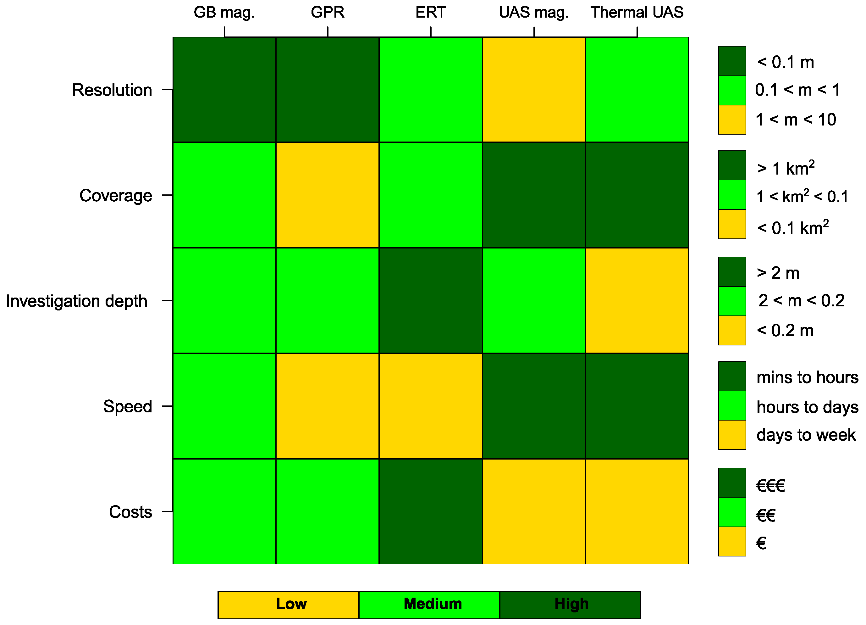
The need to study, protect, and conserve archaeological heritage has enhanced the application of geophysical techniques as non-invasive and reliable tools to investigate fragile and valuable assets. This review presents the most popular geophysical techniques suitable for archaeogeophysical investigations, namely, magnetometry, ground penetrating radar, and electrical resistivity tomography, together with a series of multiparametric measures taken from aerial platforms (UAS). For each method, we recall the basic physical principles, illustrate the operative procedures for field investigation, and provide indications about data processing and modeling. We propose a flowchart to address reliable and effective geophysical investigations, from its planning to the development of the final archaeogeophysical model. We underline the integrated approach, in which the combination of various techniques allows the best results in terms of resolution, coverage, investigation depth, speed, and costs to be obtained. We introduce a suite of studied cases in which this approach has been applied successfully.

1. Introduction

Geophysical techniques used in the field of archaeological research, including site preservation and Cultural Heritage conservation, have become more common over the years. The main reasons for this are: (i) they are relatively fast, useful, and low-cost tools for archaeological exploration and cultural heritage preservation [1,2,3] that can minimize excavation efforts and reduce human energy expenditure; (ii) they are non-invasive and non-destructive methods for site exploration, allowing the preservation of the investigated site; (iii) they allow for the position of buried archaeological remains to be precisely defined; and (iv) they allow reconstruction of the site history, e. g., natural phenomena such as earthquakes and eruptions, through the integration of other disciplines.
After three-quarters of a century of archaeo-geophysical investigations, we can undoubtedly affirm that this discipline works very well, as evidenced by the thousands of worldwide surveys that have successfully mapped buried archaeological remains [4,5]. Consequently, geophysical exploration techniques can be considered a strong and powerful investigation tool for uncovering archaeological structures and characterizing their features. The steps in a modern geophysical study applied to archaeological research are summarized in the flowchart shown in Figure 1.
For such investigations to be successful, it is essential to first establish the archaeological objectives of the investigation and to establish whether and how geophysics can contribute to their achievement. The choice of the physical parameters to be investigated is linked to both the materials and the lithology. Therefore, it is necessary to opt for physical parameters able to show the greatest contrast with respect to the ground. This reasoning guides the choice of one or more geophysical techniques and the setting of all the acquisition parameters. Field data acquisition cannot be separated from data georeferencing, which today is increasingly performed through photogrammetry aided by Unmanned Aerial Systems (UAS). The georeferenced data undergo a preprocessing step that consists of filtering and transformation followed by contextual visual analysis. This step is useful for the calculation of information characteristics, and especially for solving the inverse problem. Inversion should be constrained by a priori information and supported by the simulation of synthetic geophysical models. The georeferenced inverse models are finally compared with independent data. In this final step, acquisition via different geophysical techniques allows for joint interpretation of the different inverse models obtained [6,7,8], increasing interpretation reliability and developing the archaeo-geophysical model.
The geophysical techniques mostly used in the archeology and cultural heritage fields [9,10] include electrical resistivity, magnetics, and ground penetrating radar (GPR), which are the techniques discussed here. These three techniques are based on different physical principles, investigate different physical properties, and reach different soil depths. Magnetometry measures the susceptibility contrast between the soil and buried archaeological finds. GPR exploits the reflection and refraction of electromagnetic pulses caused by variations in electromagnetic properties. Finally, electrical resistivity tomography helps to identify compact masonry blocks or buried cavities. These techniques are fast and quite effective in the case of a compact isolated source with limited depth, which is precisely the type of source that generally occurs in archaeological investigations. As the information obtained in this way is linked to different complementary physical properties, their integration combines the capabilities of each technique, allowing for a more complete survey of archaeological characteristics.
Generally, we refer to “near-surface” to indicate the uppermost meters from the surface [11], although deeper prospection can be performed as well. Not all near-surface methods are wholly suitable for field application. Here, we have chosen to deal with the most suitable and most commonly used techniques. Other techniques such as spontaneous potential, microgravity, radiometric, and seismic techniques are rarely applied to archaeological research due to the problems of low resolution obtained, insufficient ability to identify archaeological targets, and to the physical and studied parameter not being representative of archaeological structures. In this regard, seismic refraction techniques work best in the presence of sub-horizontal stratification, in which the seismic velocity increases with depth. Seismic refraction becomes less useful, and interpretation becomes very qualitative and difficult, when there are velocity reversals; this is typical of walls, footings, or foundations on top of slower sedimentary material as well as of three-dimensional objects such as burial sites or subterranean voids.
The anomalies detected in geophysical surveys can be a valuable resource in addressing excavations in partially unexplored sites. However, measurements in the archaeological field often have a low signal-to-noise ratio, which is usually caused by: (i) problems related to the measurements, (ii) the presence of other human activities, and (iii) disturbances due to the geological environment, for instance, topsoil magnetization caused by natural phenomena [12,13]. Nevertheless, geophysical surveys prove suitable because of their high benefit-to-cost ratio and the high cost of archaeological excavations.
Following recent advancements in the geoinformation domain, photogrammetry now represents a very important tool in the archaeological field, and is used in surveying architectural details via Unmanned Aerial Vehicle (UAS; [14]). UAS data can be processed using structures from motion (SfM) photogrammetry; the highly detailed orthophotos and digital surface models (DSM) generated in this way can then constitute a reference map used for planning geophysical prospections. This approach can help in the 3D reconstruction of archaeological objects.
Geophysical instrumentation is constantly improving in sensitivity and acquisition speed, and new multi-sensor arrays allow large areas to be covered quickly. The availability of high-resolution remote sensing techniques allows archaeological studies to be carried out using multiscale and multitemporal approaches that combine various high-resolution remote sensing techniques, such as satellite (optical and radar data) and aerial (photographic, infrared, and lidar data from airplanes and unmanned aerial vehicles), with ground acquisitions that foresee the integration of various geophysical techniques. The multiple purposes involved concern historical reconstruction, preventive archaeology, conservation of archaeological and monumental heritage, and non-invasive diagnosis through microgeophysical techniques. In recent years, geophysical techniques have widened the possibilities of studying the transformations undergone by monuments over the centuries, thereby providing support for restoration projects [4,15,16,17,18]. To minimize interpretative ambiguities, various non-invasive techniques have been used jointly, for example: GPR, terrestrial laser scanning (TLS), and infrared thermography (IRT) [19]; GPR and electrical resistivity tomography (ERT) [20,21]; GPR and magnetometry [22]; and GPR, IRT, and ERT [23].
Furthermore, geophysical techniques are increasingly supported by 3D modeling of archaeological sites. The support of aerial photogrammetry allows accurate control of measurements in the investigated area, high-resolution 3D reconstruction of the landscape and archaeological features by Digital Surface Modeling (DSM), and possible comparison of future archaeological excavations or morphological surveys [17]. In this regard, the integrated use of unmanned aerial system (UAS) photogrammetry and TLS [24] as well as of UAS photogrammetry and GPR [25] have been presented. Finally, the recent diffusion of UAS equipped with thermal imaging cameras and magnetometric sensors or electromagnetic sensors has allowed their use in IRT and magnetic and electromagnetic measurements [8,26,27,28].
In the following three sections, the principles of the three most commonly used geophysical techniques in the fields of archaeology and cultural heritage are briefly discussed; for each technique, we present the issues along with the most recent proposals, then analyze application cases in which the most recent innovations are applied. Finally, in the fifth section we present the most recent advances in aerial archeology techniques and discuss their integrated use with geophysical techniques through the examples of several field cases.

2. Magnetometry

2.1. Basic Principles of the Magnetic Method

Magnetometry is probably the oldest near-surface geophysical technique [29], and it remains among the most widely used and effective geophysical techniques employed for the geophysical investigation of cultural heritage sites. In particular, the magnetic method has provided considerable results in archaeological exploration surveys [30,31,32,33,34]. The magnetic technique measures the magnetic field to detect anomalies, with the field’s characteristics controlled by several variables. While the measured field is due to the Earth’s magnetic field for its larger part, rocks or any other object containing magnetically susceptible minerals exhibit induced magnetization ( J I ) proportional to their own susceptibility indexes ( χ ), a constant usually expressed in SI units. In addition, rocks or other objects may possess a natural remnant magnetization ( J N R M ) that is independent of the external field. The total magnetization ( J T ) is the vector sum of all these components.
Therefore, the measured magnetic field is the result of the combination of various fields mainly ascribable to: (i) mineral-bearing rock types in the upper part of the crust, (ii) daily oscillations associated to the activity of the sun [35,36], (iii) unpredictable large-amplitude magnetic storms related to sunspot activity, and (iv) anthropogenic causes [37]. Other variations occur over the longer term; however, these do not affect the measurements involved in archaeological or cultural heritage-oriented investigations.
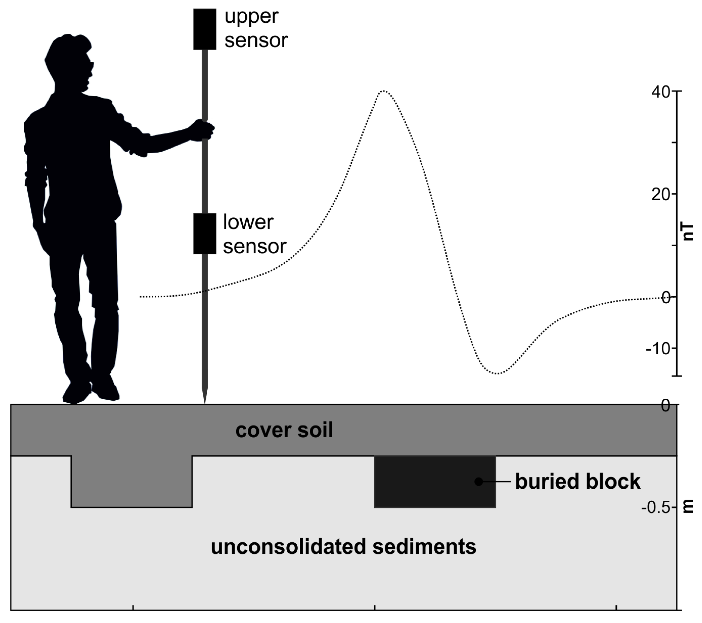
Among the sources of anthropogenic origin, there are various types of sources due to archaeological features. Buried features such as stone masonry structures usually have different magnetic properties from both the surrounding environment and the covering terrain. Such differences result in anomalies on the order of a few nT (Figure 2). Buried metal objects or traces of human activity induce anomalous signals; these can reach the order of several tens of nT, and even up to hundreds of nT in the presence of shallow ferrous objects [34]. Note that because of the dipolar nature of the magnetic field, the observed anomalies are commonly dipolar (Figure 2).

2.2. Magnetic Method: Acquisition and Instrumentation

The scale of a magnetic survey can vary by several orders of magnitude according to the objective of the investigation. The coverage, resolution, and efficiency of a magnetic survey are the direct consequence of the type of platform employed. Applications targeted to archaeology employ ground-based measurements or low-altitude surveys carried out by UAS to obtain up to decimetric resolution for the near-surface layer. Ground-based measurements can be performed by a walking operator or using a lightweight vehicle, e.g., a hand cart.
The overall setting of a ground-based magnetic survey must be chosen to bring out magnetic features at very shallow depths. The area should be covered uniformly with rectilinear parallel paths travelled in opposite directions and arranged conveniently with the local logistical conditions, keeping in mind that certain instruments must be oriented according to the geomagnetic field. The sampling frequency and progress velocity should be calibrated to obtain measures with an interdistance that is homogeneous and comparable with the dimension of the expected features to be detected. Similarly, the spacing between two following paths should be of an adequately dimension, considering that most of the common target features are elongated objects such as buried foundations, walls, or roads. Nowadays, most instruments are equipped with GPS/GNSS systems that provide high-precision absolute time and position for each magnetic measure, simplifying field operations. For long-lasting surveys, it is recommended to use a fixed magnetometer to perform static measurement in order to evaluate the diurnal variations and correct the readings of mobile instruments.
The sensors most typically employed measure the total magnetic field; however, sometimes it is useful to measure the three components independently, or to evaluate the gradient along a particular direction. Gradiometry requires a pair of conveniently spaced sensors performing simultaneous magnetic measurements; this arrangement is particularly recommended in archaeological prospection. Usually, gradiometry is performed to measure the vertical gradient, with two sensors aligned upright (Figure 2). The distance between the sensors should be scaled to the amplitude of the expected anomalies; for most cases, it is shorter than 1 m. Gradiometry has several benefits; the measure is independent from any temporal variation, and is able to isolate signals from shallow sources (i.e., archaeological features) while being almost insensitive to deeper large-scale sources fedi2017geomagnetometry. A disadvantage, however, is that pitching motions during walking mean that the instrument–operator system produces imperfect vertical alignment and small variations in the sensors’ distance, thereby introducing high-frequency noise into the gradiometry data.
Three types of magnetometers are usually employed in archaeological prospection: fluxgate, proton precession, and cesium (or alkali vapor) magnetometers. All rely on different physical bases; however, their functional principles are not treated here, as the topic is beyond the purposes of this review. Detailed information about these devices can be found in [29,30,38]. Here, we provide a comparison between the characteristics of the three basic types of magnetometer in terms of sensitivity, positive and negative aspects, possible applications, and degree of suitability for their use in archaeological or cultural heritage applications (Table 1).
All three types of device are sensitive enough to detect anomalies of archaeological origin; however, the proton precession magnetometers are generally more suitable because the obtained measurements are theoretically independent from the surveying direction. A type of proton precession magnetometer called the Overhauser effect magnetometer has gained popularity for archaeological prospection over the last 20 years [39]. It is a reliable device, and is characterized by a better resolution compared to traditional proton precession devices. As a general rule, the choice of sensor should take into account all of its aspects, not merely the best performance, as other considerations may make another choice the most appropriate one for a specific case.

2.3. Data Correction, Processing, and Interpretation

For successful interpretation of magnetic data, processing the data to isolate and enhance any anomalies which could be weak or masked by magnetically noisy anthropic soil is a fundamental step. Here, we provide an overview of data processing and a number of the most common procedures used to treat raw magnetic and gradiometry data. Interested readers may refer to the specialist literature (e.g., [29,40,41]) for more details.
After punctual data interpolation on a regular grid, basic data processing encompasses de-spiking to remove the outliers [40,42]. The bidirectional acquisition mode causes typical noise, resulting in a striped pattern as the data are shifted along the progress direction. This effect is often referred as the “heading error” [43], and is partly ascribable to the dependence of the measurements on the orientation of the sensors and partly to the differences in symmetry, even slight, of the instrument–operator system between two adjacent lines. The latter component can be either due to the undulating gait of the operator and consequent inability to follow a perfectly straight lines, or to errors in the positioning of the measurements due to the intrinsic error of the positioning system. Quick correction can be obtained by averaging the acquired data along each line of the surveyed area ciminale2001aspects. A similar banding pattern is often encountered in archaeological fields when the soil is used for agriculture; in such cases, directional filters are able to remove the ploughing effect [44].
In order to identify the anomalies and outline their edges, the literature has proposed a multitude of processing methods [34]. The most widely adopted filtering method is reduction to the magnetic pole (RTP). RTP was first proposed by baranov1957new, and is a widely used filter that can transform the observations as if they were obtained at the geomagnetic pole, where the vector of the magnetic field is perpendicular to the Earth’s surface. In fact, owing to the inclination and declination of the Earth’s magnetic field, the magnetic anomalies relative to a source have reduced amplitude, are bipolar or asymmetric (Figure 2), and are shifted to the south (north) in the northern (southern) geomagnetic hemisphere. Therefore, after RTP correction, the anomalies are centered over their sources. Analogous results to those of RTP are obtained by calculating the 3D analytical signal of the total magnetic field [29,45] without any assumptions with regard to the magnetization of the medium. The analytic signal is calculated by combining the magnetic gradient in the three directions; the amplitude is provided by the square root of the sum of the squares of the three derivatives. The amplitude (or energy envelope) of the analytic signal is independent from the phase anomaly, and its maximum is located on the vertical of the edges of the anomalous signal.
The delineation of the edges of anomalies is commonly based on the horizontal and vertical derivatives (e.g., the analytical signal amplitude) [46,47,48,49,50,51]. Methods of discriminating the interference deriving from overlapping anomalous sources at different depths have been proposed as well [52]. Buried archaeological features such as foundations or walls are usually characterized by rectilinearity and sharp edges. The techniques for edge detection are somewhat simplified by such regular patterns, however, the results should always be taken with appropriate caution in order to avoid misinterpretation.
Magnetic data used for archaeological prospection are usually visualized as a 2D map with a colored scale bar calibrated to the values’ range, with a sub-metric spatial resolution being recommended. The interpretation of magnetic maps, even after the appropriate processing, is not always straightforward, and may not be reliable enough to allow for robust interpretation. For thorough interpretation and accurate identification of archaeological objectives before excavation, the data should pass through a modelling stage.

2.4. Magnetic Modelling: Forward and Inverse Problems

Magnetic modelling aims to calculate the magnetic properties of the involved materials and their geometrical arrangement given the observed data. In simple forward models, the anomaly associated with an initial model is computed and then compared with observed data. The initial model, typically constrained by independent information (i.e., other geophysical data), can be successively adjusted in an iterative way to minimize the misfit [53,54]. Early models were based on simple shape bodies, with their anomalous signals being analytically calculated and then compared to the observation in a 2D profile (e.g., [55,56]. An exhaustive review of forward modelling algorithms in the literature can be found in [29].
The inverse problem aims to automatically build a model that accounts for observations without any initial model; the observation itself should be reproduced within a given error threshold. The solution to the inverse problem is non-unique, meaning that several configurations may reproduce the observations within a given error tolerance. The problem can be solved iteratively by means of a process of optimization of the solution of the forward problem. In archaeological prospection, external information can be easily retrieved from the literature or independent sources; the range of investigation is a limited variable, the values of the susceptibility indexes χ of rocks, soils, or metals are known, and on a case-by-case basis the arrangement (or shape) of the features can often be presumed. In this context, the calculation of the best numerical solution becomes a much simpler task and inversion can be performed by inverting either the geometry of the source, its magnetic properties, or both. Many algorithms have been proposed in the literature for 2D and 3D inversion, and a number of these are specifically devoted to archaeological-scale applications [10,54,57,58,59].

2.5. A Field Application: The “Capo Lilibeo” Archaeological Site (Italy)

A field application of magnetic prospection applied to archaeological research is presented here [60]. Lilibeo is an ancient city where Punic, Greek, and Roman domination followed over the centuries. It is located on the westernmost cape of Sicily (Italy). A magnetic survey was carried out using an Overhauser GEM-19 magnetometer–gradiometer from GEM Systems, which has an accuracy of 0.2 nT.
The sensors were oriented orthogonally to the progress direction, meaning that they had the same arrangement in the roundtrip tracks. The survey area measured 65 m by 93 m, and the acquisition was performed by walking along parallel lines spaced by 0.5 m with a sampling frequency of 5 Hz. At this frequency, and considering the walking pace of the operator, the measurements were located at every ∼0.2 m, on average, along the progress direction. The survey resulted in 130 magnetic profiles and more than 58,000 readings.
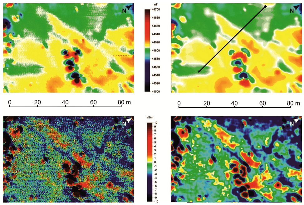
The magnetic profiles are affected by noise;; many of them are point sources, such as localized highly magnetic minerals in the surface soils, or ferrous objects, which are very probable in the soil of an archaeological site. Therefore, the outliers were removed with automated de-spiking; later, each profile was filtered with a moving average. The bi-directional acquisition mode causes the typical striping noise mentioned above. The data were corrected using fifth-order polynomial regression and applying a moving average filter with a 7 × 7 window to the data matrix (Figure 3).
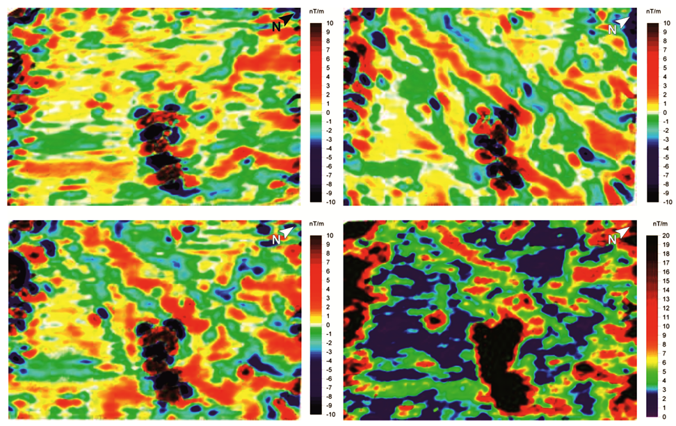
The RTP was then calculated using the filtered data. The measured field was converted into an equivalent field as if it were located at the magnetic pole. In this way, the anomalous values are located on the vertical of their sources (Figure 4). The 3D analytical signal can be obtained after calculating the vertical and horizontal derivatives, with the amplitude resulting from these three components. The main advantage of the analytical signal is that because the amplitude is phase-independent, the maximum values are aligned with the edges of the sources.
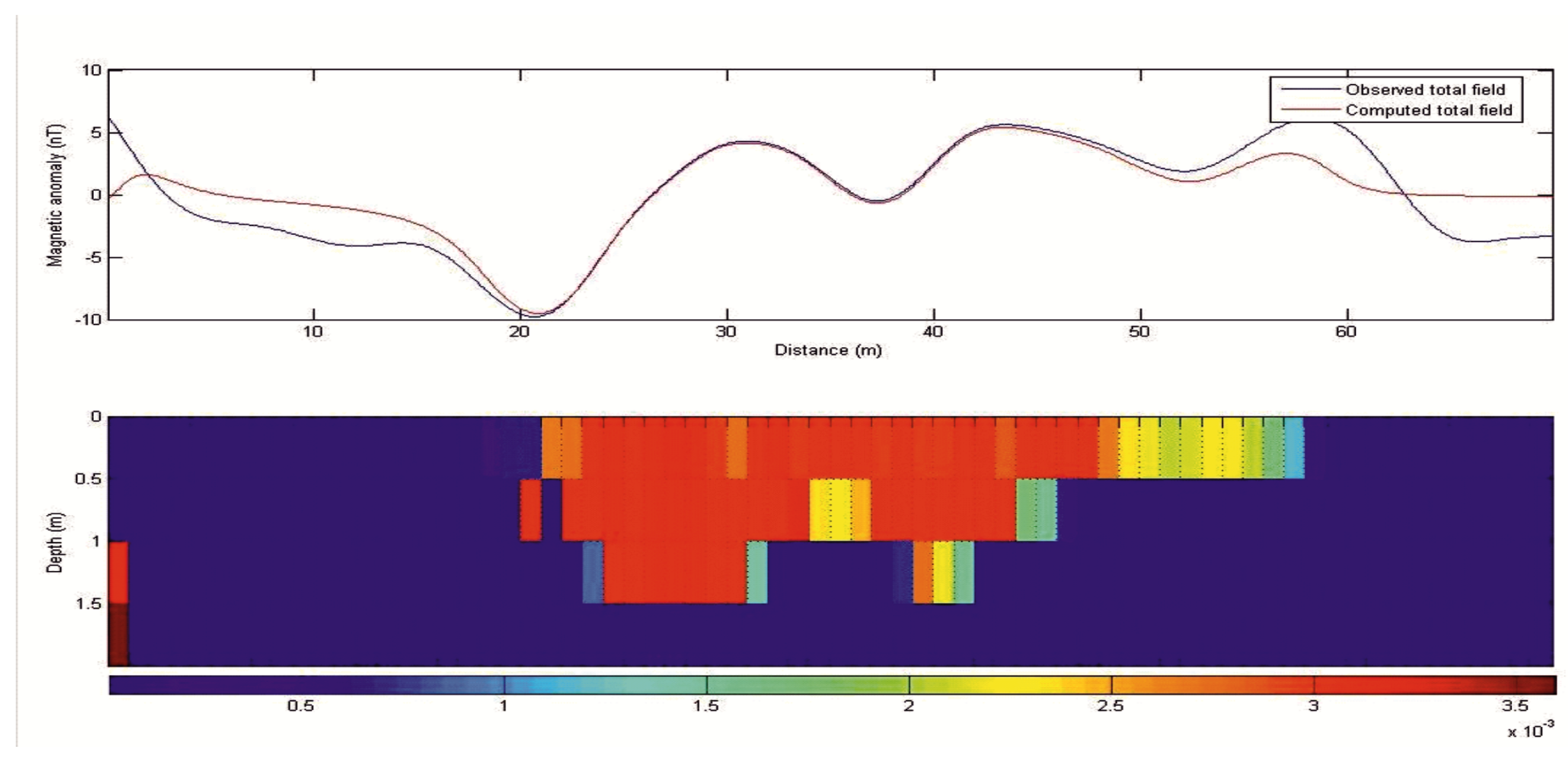
The vertical gradient was inverted along an illustrative section (Figure 5), with the track shown in Figure 3. The inversion method is known as compact inversion, and it consists of a weighted least-squares solution of a susceptibility model and its associated errors. This technique minimizes the area (or volume) of the source of the magnetic anomaly in order to maximize its compactness. Inversion then follows an iterative scheme, with consecutive adjustments being made until it converges into a stable solution.
Identifying anomalies ascribable to archaeological features is usually achieved by integrating the elaborated magnetic maps with independent observations obtained through other geophysical techniques, i.e., optical or infrared maps, ground penetrating radar, electrical resistivity tomography, high-resolution digital models of the surface, etc. The geophysical investigations at the Lilibeo site addressed the following excavations. The anomalous areas, which had amplitudes in the tens of nT and ∼±10 nT/m, were found to correspond to the remains of the foundations of buried buildings.

2.6. Remarks

A vast amount of works in the literature state the effectiveness and reliability of the magnetic method in geophysical investigations of cultural heritage, and in particular in the field of archaeological exploration. Benefits include its non-invasive nature, rapidity of execution, and relatively low cost. In addition, magnetic surveys can be integrated with GPR, ERT, TIR, and any other technique of geophysical investigation [8,42,61,62,63,64,65,66,67,68,69,70]. These combinations allows many of the limitations of individual methods to be overcome, and provide constraints for the accurate reconstruction of investigated features.

3. Ground Penetrating Radar

3.1. Basic Principles of the GPR Method

Ground Penetrating Radar (GPR) uses EM waves, typically in the frequency range of 10–3000 MHz, to map structures and buried targets in the ground [71,72]. Because of its fast data acquisition and high resolution imaging capabilities, this method is one of the most widely recommended non-destructive testing (NDT) techniques for diagnosing the condition of buildings, monuments, and other ancient artefacts [73,74,75,76].
GPR prospecting is often used in archaeological investigations [74,77,78,79,80], where it has proven helpful for revealing information about the position of ancient settlements, which is helpful for scheduling future excavations [21,69]. GPR is an effective method in the field of cultural heritage for performing structural diagnostics on walls [81,82], where it has been used to identify voids and humidity [19], fractures [83], and detached areas of frescoes and mosaics [84].
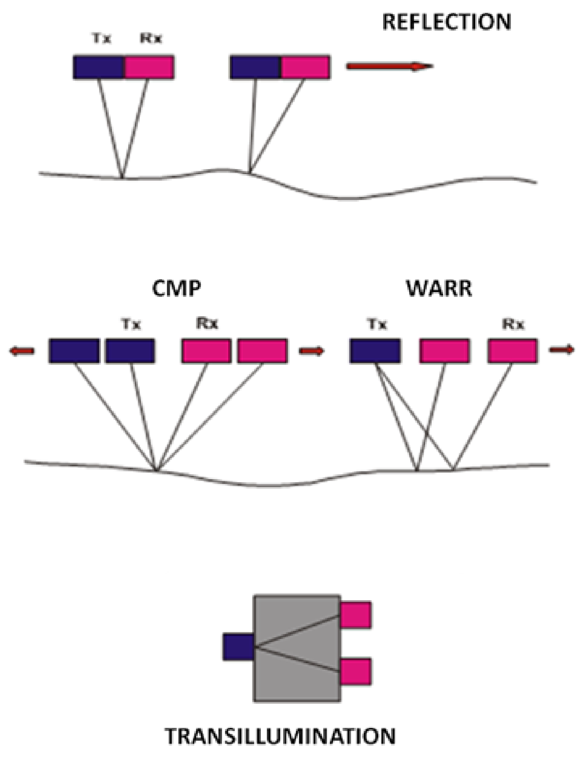
In GPR, a radar-transmitting antenna emits an electromagnetic impulse which can be reflected or scattered by a dielectric discontinuities in the ground and gathered by a receiving antenna. The time elapsed between the pulse being sent and being received provides evidence of depth. Changes in the wave’s angle of reflectance caused by buried materials or soil changes in the ground are measured by a sensitive antenna and interpreted by the operator [85]. The electrical properties of geological materials are primarily controlled by the water content. Variations in the electrical properties of soils are usually associated with changes in volumetric water content, which in turn give rise to radar reflections. The velocity and attenuation are the factors that describe the propagation of high-frequency radio waves in the ground [86]. These factors depend on the dielectric and conductivity properties of the materials. The main factors that affect the radar signal range in the ground are the radar system performance, level of attenuation in the ground, and the reflection properties at the boundary where the electrical properties vary. From the attenuation values in geological materials and the nature of the frequency dependence, it follows that for a given signal detection threshold the maximum depth of investigation decreases rapidly with increasing frequency; thus, almost all subsurface radar systems operate at frequencies below 3 GHz. The equipment used in all GPR systems consists of four main elements: a transmitting unit, a receiving unit, a control unit, and a display unit [87]. The transmitter produces a short-duration high-voltage pulse. This pulse is applied to the transmitting antenna, which radiates the pulse into the ground. This transmitted signal travels through the ground, with reflected or scattered signals traveling back to the receiving antenna and then to the receiver. The latter amplifies the signals and formats them for display by the control unit. Many GPR units can operate at different frequencies, and there are a variety of different acquisition techniques (Figure 6), including:
1.
The reflection technique, in which antennas are kept in a fixed configuration and move over the ground. This results in a section being displayed showing the time to the radar reflectors along the vertical axis and the antenna position along the horizontal axis.
2.
The CMP (Common Mid-Point) technique, which requires that the antennas be moved symmetrically to a fixed point.
3.
The WARR (Wide Angle Reflection Radar) technique, which uses a fixed transmitting antenna and a mobile receiver (or vice versa), which moves along a profile.
4.
The technique of transillumination, which is carried out by lowering the antennas in wells parallel to each other or making them move on the opposite walls of a building, e.g., walls, pillars, etc.
As GPR antennas are bandwidth-limiting devices, the same transmitter and receiver can be used with a number of different antennas [88]. Antennas that are located high above the ground do not work as effectively; their energy waves fail to penetrate into the ground, and most are reflected back by the ground surface. Because different antenna frequencies can be used, different vertical and horizontal resolution can be achieved. In this context, the resolution is the ability of the system to distinguish two signals that are close to each other in time, with a shorter time of the pulse width translating to a higher resolution and the highest resolution being the closest distance between two reflectors in the subsurface. GPR has the advantage of being a non-passive technique with controllable input; it is non-destructive, rapidly creates large quantities of data, and is capable of being used in both stepwise (i.e., point) and continuous monitoring modes.

3.2. Processing and Timeslice Technique

GPR data are generally subjected to processing with the aim of eliminating background noise and highlighting the anomalies being investigated. It should be emphasized that target anomalies in some investigations may constitute disturbances in others. For this reason, there is no specific standard followed in data processing. Despite this caveat, a number of processing procedures are very common:
1.
Static correction, which performs correction on each trace in the time direction; it is applied to eliminate time delays related to trigger errors.
2.
Frequency filtering, which eliminates electromagnetic noise (characterized by frequencies other than those of the transmitted signal).
3.
Energy decay, which is useful for highlighting low ranges of amplitudes of the acquired signal against the highest ones.
4.
Background removal, a 2D filter that allows temporally consistent noise to be eliminated and is useful for making certain signal portions covered by noise more visible.
5.
Kirchoff migration, which is a velocity-weighted summation computed for each point of the profile based on the hyperbolas of reflection within a preset bandwidth.
After processing and correction of all 2D radar sections, the resulting acquisition of a dense grid of transversal and longitudinal profiles makes it possible to trace a schematic representation of the subsoil using the technique of time slices (or depth slices, which are conceptually equivalent). The time slice technique [73] is now widely used for the analysis and representation of 2D georadar data acquired along parallel lines in one or two directions perpendicular to each other. This technique makes it possible to recognize the presence of any structures in the subsoil by comparing different areas using figurative comparisons.
Recently, the time slice technique has been used successfully in archaeological surveys to detect buried structures in a large number of scenarios, such as identifying ancient settlements [8,89,90,91,92], unearthing tombs and ceremonial offerings [93], and finding the foundations of ancient buildings [80,94].
Within the last few years a number of analytical techniques have been proposed which use the continuous wavelet transform and amplitude to identify buried archaeological objects (see Iqbal et al., 2022). However, recognizing materials and reflecting geometries while starting from only their 2D radar profiles is a complex procedure. The observation of time slices, which have a lateral resolving power that essentially depends on the density of the executed profiles, allows for the interpretation of observable anomalies through analysis of the geometric shapes of the anomalies as obtained by lateral correlation between the different profiles 2D acquired.
The processing of 2D data, which precedes the calculation of time slices, must be differentiated according to the purpose of the investigation and the targets being investigated. While the application of particular filters, such as the elimination of background noise, can highlight certain anomalies, it can potentially hide the presence of others.
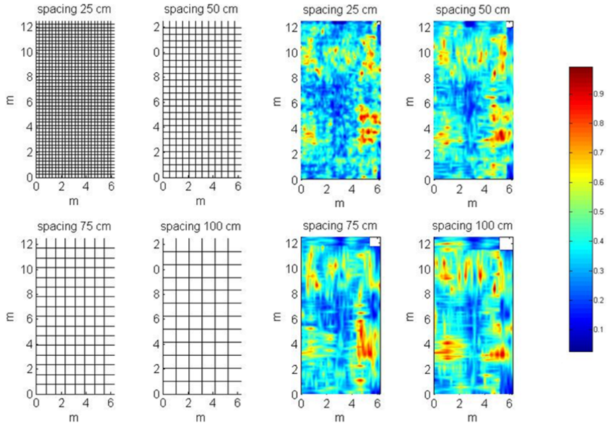
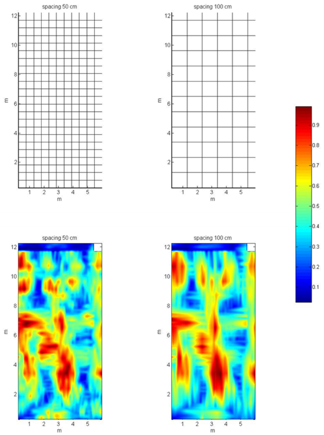
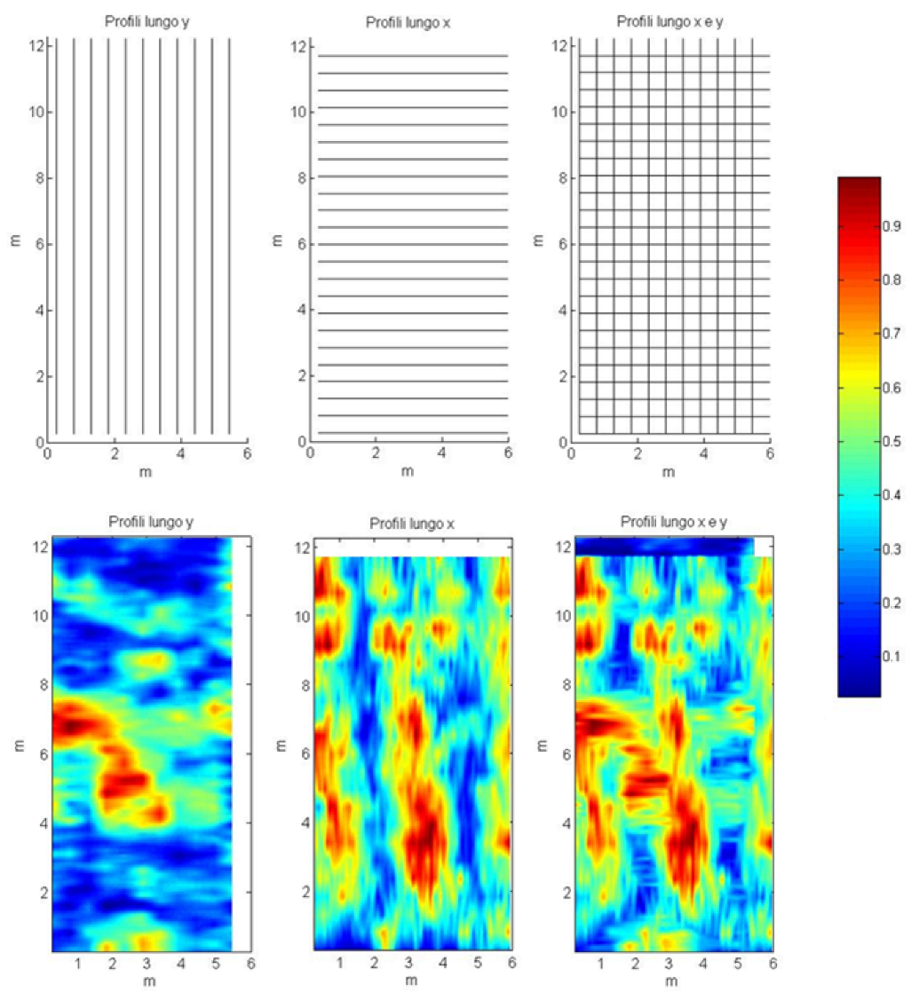
For correct interpretation of the data returned by the time slice method, accurate selection of parameters during the acquisition, processing, and construction of the time slice is necessary. In particular, to obtain valid lateral correlation between the profiles and ensure a sufficient sampling density for identification of the investigated targets, it is necessary to optimize the spacing between the profiles (depending on the characteristic frequency of the antenna used) and their direction of acquisition during the acquisition phase. Figure 7 and Figure 8 show a comparison of maps obtained with various profile spacings, allowing the differences to be observed.
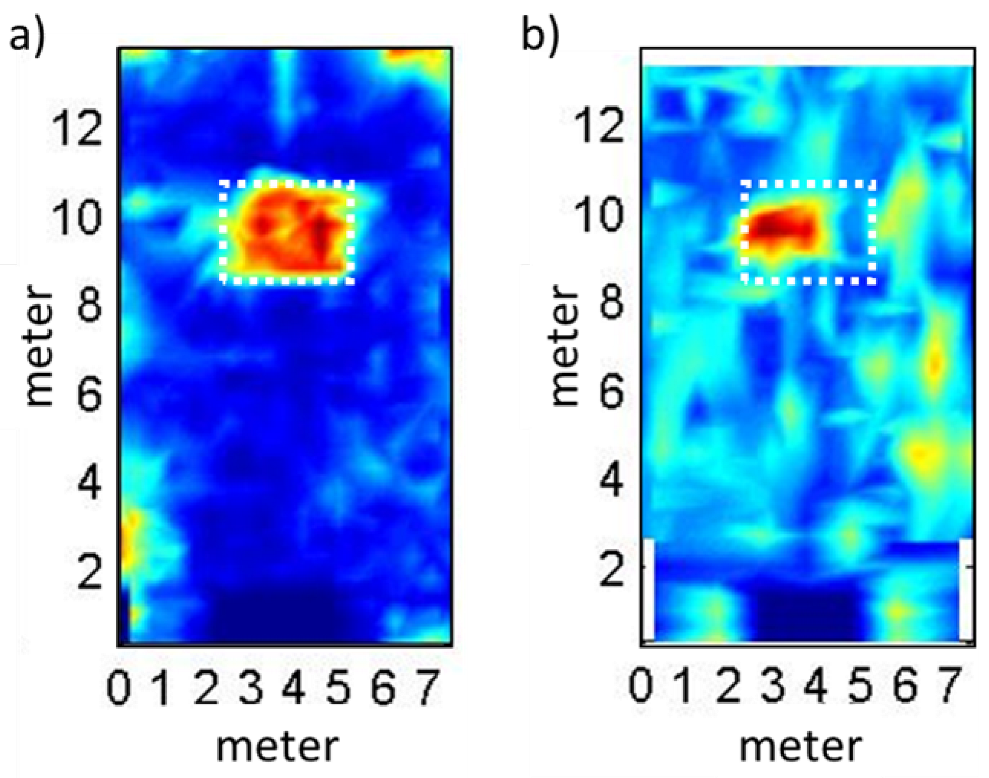
It is clear that lower spacing between the profiles leads to better resolution of the resulting map. However, this depends on the type of antenna used. With a 400 MHz antenna, it is possible to notice deep differences between the time slices acquired with spacing of 50 cm and those acquired with spacing of 100 cm; however, when using of a lower frequency antenna, such as 100 MHz, these differences are not as obvious. This leads to the conclusion that smaller spacings may not necessarily improve the quality of the data, and that above all the spacing should be chosen based on the frequency of the antenna being used. This depends on the resolution, and in turn on the minimum size of detectable objects).
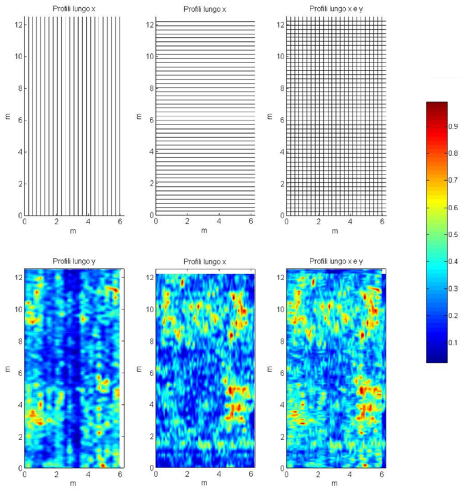
Although the acquisition of profile grids is always preferable, the use of only one acquisition direction can often be sufficient (Figure 9 and Figure 10). Obviously, this depends mainly on the referential direction of the anomalies being investigated as well as on the density of the acquired profiles. Finally, the optimization of certain parameters relating to the calculation of the time slices, especially the size of the rectangular analysis window, the number of slices, and the refinement of the rendering techniques, allow for faithful geometric reconstruction of anomalies, which can facilitate their interpretation in both geophysical and physical terms.
Therefore, the proposed tests show that during the acquisition phase even less experienced operators should pay close attention to the parameters chosen, especially for the minimum and maximum separation of the profiles acquired and their direction in relation to the directions of the anomalies investigated. It is useful, in the absence of precise information on buried structures, to acquire the profiles in two perpendicular directions; this allows for correct localization and better geometrical definition of anomalies, especially in the presence of depolarizing objects. Moreover, in order to obtain good resolution the results should be acquired with a spacing of 25 cm (for a 400 MHz antenna) and 50 cm (for a 100 MHz antenna), though this should be reviewed in light of the dimensions of the expected anomalies. While higher acquisition speeds do not seem to worsen the resolutive power of this method, higher speeds could certainly introduces noise due to the inevitable increase in antenna tilting, which can affect the correct spatial referencing of the data as well.

3.3. Issues and Proposals for Archaeology and Cultural Heritage

Archaeologists have employed this technical procedure for many years, and it is common in other scientific fields as well, such as geology, environmental studies, and engineering. Archaeological geophysics involves a manner of collecting data that permits field archaeologists to learn about and map underlying archaeological features that are otherwise impossible to discern using traditional field methods. Archaeologists take advantage of the physical and chemical changes within the ground relative to the presence or absence of subterranean items. Using highly sensitive instruments, a specialist technician can measure, map, and interpret the data signals received by the GPR system and extract helpful information. Generated GPR maps provide primary data that is used to direct the establishment of excavation sites or to identify sensitive areas containing cultural remains, such as burial sites, that would be better left untouched; therefore, this information can guide archaeologists and help them to avoid disturbing these locations. The greatest advantage of ground penetrating radar methods is that they gather an immense amount of information about the near-surface in a totally non-invasive and non-destructive way, permitting large sites with concealed remains to be viewed and analysed efficiently and accurately while protecting and preserving them. While small EM antennas can be hand-held and ‘walked’ across an archaeological site, many larger units are usually placed directly on the ground and moved by being fitted onto a non-metallic sledge arrangement and pulled in a long straight line. All sedimentary strata and buried artefacts in the ground have peculiar physical and chemical properties that influence the EM spread’s velocity, electrical conductivity, and magnetic permeability. Differences or variations in the returned wave energy indicate underlying archaeological features such as architecture or artefacts. However, if the archaeological features are composed of similar material to the matrix or have identical physical and chemical properties, the lack of discernible variation renders such objects ‘invisible’ to GPR equipment.
Using GPR, archaeologists can detect ancient roads, house floors, architectural features such as walls, middens, and wells, geophysical features such as riverbeds, and even smaller objects such as tools and other artefacts. It may take many years for a GPR archaeologist to become proficient at ‘decoding’ the recorded display information. When perfected, however, using ground penetrating radar before or during archaeological excavations has proven to be an invaluable exploratory tool.

3.4. A Field Application: The Ex-Oratory of Santo Stefano Protomartire in Palermo

A fascinating case history regards a GPR survey carried out on the Ex-Oratory of Santo Stefano Protomartire in Palermo, Sicily, is presented here. Located in the famous Monte di Pietà square in the heart of the historic old downtown of Palermo, the Oratory was built by the Genoese in opposition to the church of San Giorgio dei Genovesi. The Oratory included a chapel with painted coffered ceilings, frescoed walls, majolica flooring, and underground rooms used as mortuary crypts. In the seventeenth century, it was embellished with stuccos by Giacomo Serpotta and his son Procopio, wooden furnishings of exquisite workmanship, and pictorial works of the Genoese artist Bernardo Castello, who in 1614 produced fifteen large canvases representing the life of Santo Stefano. In the early twentieth century, the monument was seriously degraded to the point that it was seized for fear of collapse. In 1998 the Archiepiscopal Curia of Palermo entrusted it to Extroart, which converted it into the International Multimedia Centre for Contemporary Art, starting its restoration with the realization of exhibitions, concerts, projections, and symposia of sculpture, painting, music, and architecture.
Georadar investigations were carried out inside the oratory to locate possible crypts buried under the paving of the central nave. Georadar data were acquired using a GSSI (SIR 3000) system. Based on the supposed depth of the structures investigated, a 400 MHz antenna was used. This antenna was able to reach a depth of about 2 m using an acquisition range of 60 ns and imposed a value of the relative dielectric constant equal to 18 (corresponding to a velocity of 0.07 m/ns), as suggested by previous calibrations and analysis of reflection hyperboles. Moreover, it was considered valuable to deepen the research using a 100 MHz antenna, which allowed for a greater depth of investigation. In particular, two grids of GPR profiles were used: the first with seven longitudinal and fifteen transverse profiles (spacing of 100 cm) for a total of 185 m with the 100 MHz antenna (Figure 11a), and the second with thirteen longitudinal and twenty-eight transverse profiles (spacing of 50 cm) for a total of 380 m with the 400 MHz antenna (Figure 11b). GPR data were acquired using a SIR3000 system (GSSI) equipped with 400 MHz and 100 MHz antennas. During the survey, GPR was deployed in reflection mode.
All the acquired data were processed using ReflexW© software through a quasi-standard processing procedure. In particular, a background removal filter was used to eliminate the constant signal in the whole profile (first air-floor reflection, etc.), followed by band-pass filtering, horizontal and vertical stacking, and the data envelope used for time slice calculation.
The presence of an anomaly in the central part of the nave is clearly visible in the georadar profiles that pass over it (Figure 12); the acquisition of a dense grid of transverse and longitudinal profiles after processing and correction of all the radar sections makes it possible to trace the schematic representation of the hypothesized crypt through the time slice technique.
In particular, Figure 13 shows two corresponding (0–20 ns) time slices acquired with the 400 MHz antenna and 100 MHz antenna, respectively. It is clear that the higher resolving power of the 400 MHz antenna and the higher density of the profiles obtained with it allow for better reconstruction of the shape of the investigated anomaly.

4. Electrical Resistivity Tomography

4.1. Basic Principles of the Resistivity Method

The resistivity survey method is one of the most widely used geophysical exploration methods in archeological exploration surveys [95,96]. It has been used to image structures on scales from millimeters to kilometers [97,98]. Over the last 30 years, this method undergone significant improvements that have let to important results in both 2D and 3D surveys [99]. This has been made possible by developments in field instrumentation, automatic interpretation algorithms, and computer software.
Electrical resistivity surveys aim to estimate the electrical resistivity of the subsurface. The resistivity survey method is based on the relationship between electrical resistivity, current, and potential, as described by Ohm’s law. Measurements are made by injecting a current into the ground through two current electrodes and measuring the difference in the resulting voltage at two potential electrodes [100].
The solution to the inverse problem is needed to obtain resistivity models, starting from the measured potential and current measurements. The first step in the inversion procedure is the choice of a suitable algorithm to solve the forward problem. This consists of choosing a discrete resistivity model and calculating the electrical potential field in the point electrodes of the considered acquisition sequence. The forward problem is usually solved by applying finite difference [101,102,103] or finite element [104] approximations of the differential equations that guide the current flow. The inversion procedure starts with a simple initial model (usually a homogeneous half-space), then iteratively changes the resistivity of the model cells using methods that minimize the misfit between the observed and predicted apparent resistivity values. The most commonly used method for resistivity data inversion is the damped least-squares method [105]. Due to frequent ill-posedness and ill-constrainedness, the inverse problem must be made stable by introducing smoothness or robust constraints during the inversion procedure [106]. An L1-norm criterion can be used to produce ‘blocky’ models for homogeneous zones separated by sharp boundaries [107,108]. Inversion techniques used for 2D ERT can be extended to 3D ERT with relatively few modifications [109]. However, 3D ERT inversions can require minutes to hours to perform, depending on the size of the dataset.

4.2. Acquisition with Multi-Electrode Systems

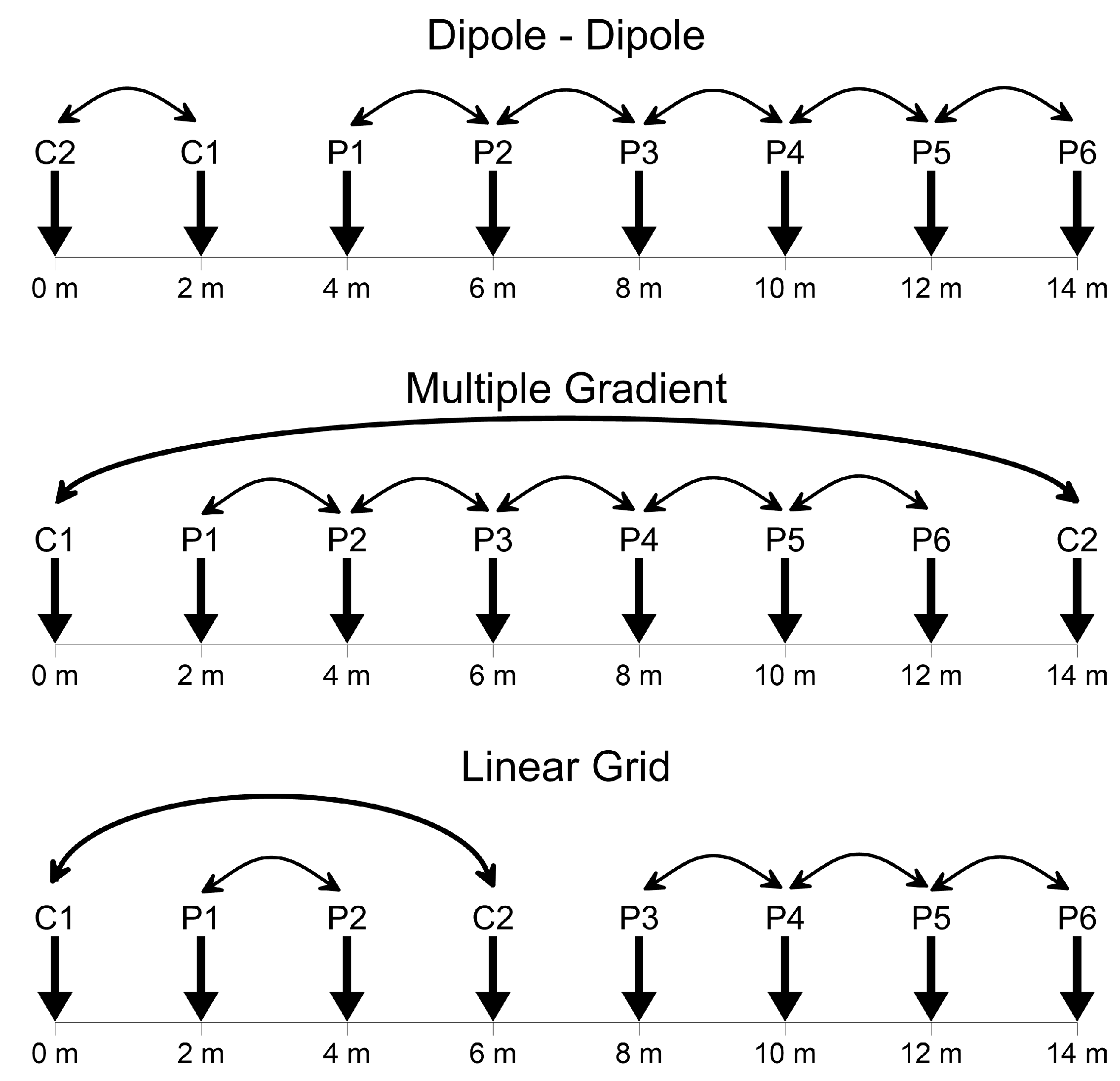
Different electrode arrays have been used for 2D and 3D resistivity surveys (Figure 14). The advantages and disadvantages of these arrays depends on many factors, among which are their sensitivity to the target of interest, signal-to-noise ratio, depth of investigation [110,111], lateral data coverage [112], and more recently the efficiency of using them in multi-channel systems [113,114]. In recent years several new arrays, such as the multiple gradient array in the original version [115] or the multi-coverage modified version [114,116], have been designed for use in multi-channel systems.
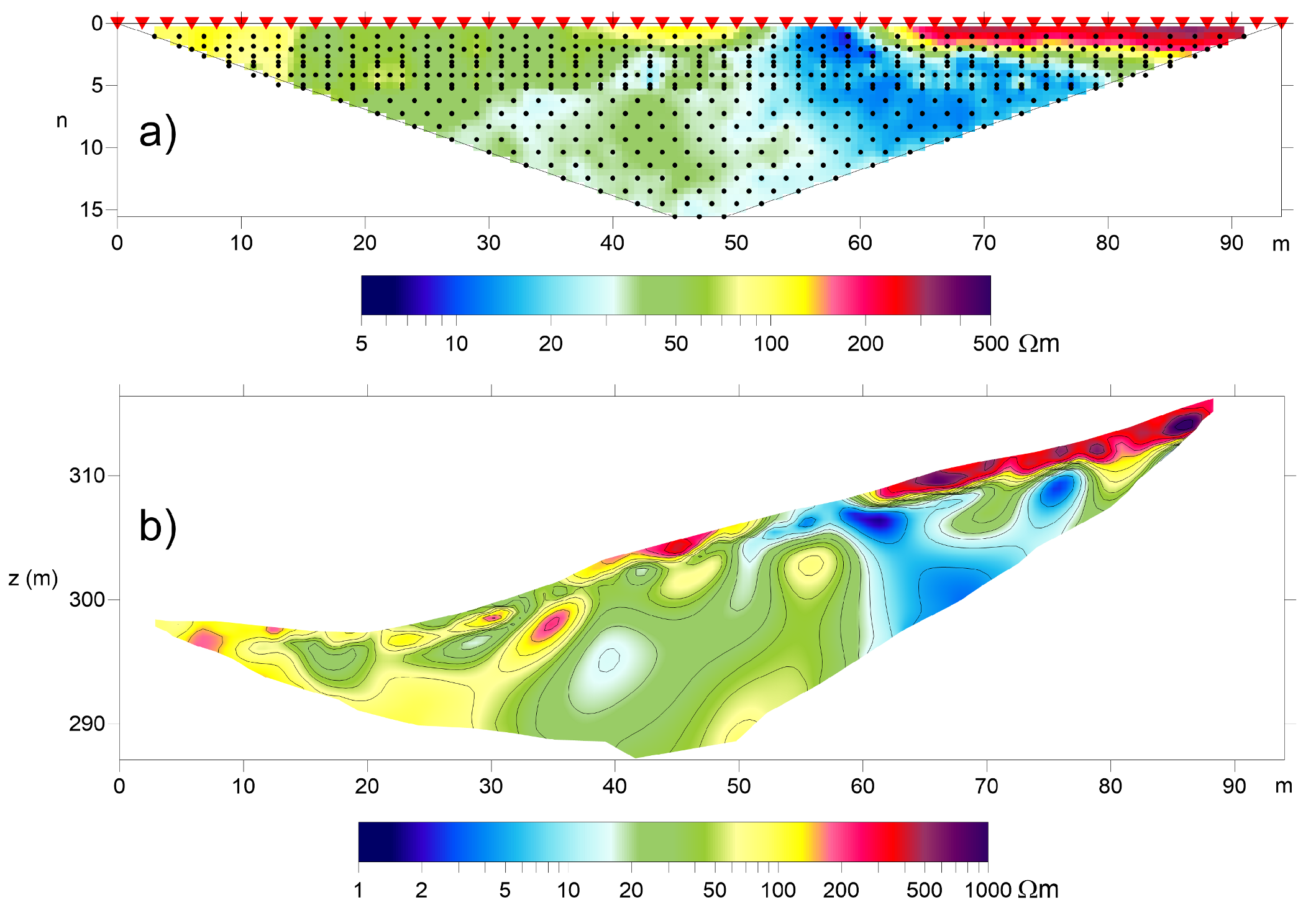
The 2D resistivity profile is carried out using specified sequences of measurements with different locations and different electrode spacing. Figure 15a shows a typical representation of apparent resistivity data acquired through a 2D Electrical Resistivity Tomography (2D-ERT) for a dipole–dipole sequence.
There are many commercial multi-electrode resistivity systems capable of connecting up to several hundred electrodes at once, which can greatly reduce survey times. In fact, for each current dipole, the voltage measurements can be made between many different pairs of potential electrodes. New data acquisition techniques, such as using multiple gradient arrays [114,115], have been designed for multi-channel systems.
Many different techniques and algorithms have been proposed [113,117,118] to optimize the choice of the array sequence in order to fully exploit the capabilities of the new multi-channel resistivity meters while at the same time achieving more reliable imaging of the subsurface. In this context, the discretization of the subsurface model into a large number of rectangular cells and the development of fast and stable data inversion algorithms [106,119] have allowed the widespread use of 2D electrical imaging surveys beginning in the early 1990s.
2D ERT surveys (Figure 15b) are more widely applied commercially than 3D ones because of their rapid execution at relatively low cost with lower equipment requirements compared to 3D tomography. 2D ERT implies the assumption that the geological structures under investigation do not change in the direction perpendicular to the survey line. However, when this assumption is not reasonable, i.e., in the presence of structures that cannot be simplified to 2D with respect to the survey line, the 2D inverse model can lead to erroneous interpretations [120,121].
3D resistivity surveys are used when more accurate results are needed to investigate 3D geological, archaeological, and engineering structures. Today, 3D resistivity surveys are not used as frequently as 2D ones; however, they are increasingly more widely used in complex areas for environmental and engineering problems [122,123,124]. A complete 3D Electrical Resistivity Tomography (3D-ERT) survey requires the placing of electrodes in the form of a 2D grid with measurements in different directions. Early 3D surveys used a pole–pole array [119] due to its simplicity when old four-channel resistivity meters were used. The recent development of multi-channel resistivity meters has led to the use of dipole–dipole and Wenner–Schlumberger arrays becoming more suitable, along with even more optimized arrays for multi-channel acquisition in surveys that involve thousands of electrode positions [114,115,122,125,126].
Most frequently, 3D data sets are collated from independent 2D survey lines [127,128,129] using a parallel line or orthogonal line arrangement [130]. These surveys can be arranged in regular or irregular lines, and can be used for 3D inversion. In these cases, the parallel line arrangement is effective in identifying the approximate location of the anomalous body, while the orthogonal line arrangement is optimal for identifying a target body near the line intersection. This strategy greatly reduces the cost of 3D surveying.
Unfortunately, in heavily urbanized areas or inside existing buildings there are few free spaces where parallel electrode lines are possible; most of the time, researchers are forced to use the spaces available between buildings, walls, and columns [131]. Furthermore, separation between parallel streets or corridors can be much greater than the minimum recommended distance when seeking to design regular grids for 3D resistivity surveys. In addition, drilling to insert the electrodes into the pavement may be prohibited due to buried electric cables, telephone lines, water, gas, or drainage pipes, or simply because the studied structure is a historical monument. To overcome these problems, unconventional non-straight arrays have been proposed to investigate beneath surfaces that cannot be reached directly by electrode arrays. In an L-array [132], the electrodes are distributed to form an L shape, which can, for example, exploit two perpendicular roads adjacent to a building. However, when using this array the tomography suffers from a low resolution in the center of the investigated area. A modified version of the L-array, called an "L and Corner" array, was proposed by [133], considering among other modifications the possibility of adding a square or rectangle to the survey. However, the results show lower resolution compared to those obtained from a regular grid of electrodes.

4.3. Issues and Proposals for Archaeology and Cultural Heritage

Electrical resistivity tomography is useful for the identification of structures characterized by a high resistivity contrast compared to anthropic sediments, which generally have medium to low resistivity values due to their clayey content. Archaeological remains made up of stone materials have much higher resistivity than the ground, and consequently are easily identifiable by a resistivity survey. Furthermore, empty underground environments (such as tunnels, chambers, tombs, etc.) are easily detected due to the high resistivity of air. Conversely, humid zones characterized by high water content can be identified by their low resistivity. The resolution achieved by ERT strongly depends on the chosen electrode distance; for archaeological investigations on the ground this is usually around 1–2 m, though it may be less in indoor applications such as on pavement or walls. At the same time, the depth of investigation can easily exceed two meters, though at the expense of resolution. As ERT is a slower and more expensive method than the other geophysical methods used in archaeology, it is often used to identify humid zones, when greater depth of investigation is needed, or in conjunction with other methods such as GPR and magnetometry when an integrated approach is needed to resolve the respective ambiguities of each method.
Historically, electrical resistivity measurements have been widely used in archaeological investigations [134]. In the past, however, this technique was limited to obtaining maps of apparent resistivity or resistance of the subsoil to identify anthropic structures in large archaeological sites through the response of a fixed-geometry four-electrode array [31]. More recently, however, 2D and 3D resistivity images obtained by inversion have become increasingly popular among archaeologists because they permit more accurate identification of archaeological objectives before excavation.
In archaeology and cultural heritage applications, ERT surveys have been successfully used with different aims, including the characterization of tumuli [79,95,135,136], the mapping of different layers of human settlements [137,138,139,140], the location of buried voids, walls, and foundations of monuments [21,89,94,141,142,143,144], the identification and geometric characterization of tombs and crypts [145,146], and the study of the geological or geomorphological assets of archaeological and monumental sites [68,147,148,149,150,151]. A promising field of application is the preservation of cultural heritage [152]. The use of this method has been frequently reported in the context of structural assessment and restoration of historic buildings built on older structures [20,23,96,153,154].
In Cultural Heritage applications, ERT surveys are often carried out indoor [155], and consequently the use of metal stakes is inappropriate because of their invasiveness when applied to lapideous surfaces and the difficulty of injecting current and estimating potential. In such situations, the contact resistance between the electrodes and the medium is usually several orders of magnitude greater than the resistance of the medium itself. A suitable solution is to insert the current electrodes into small perforations on the surface, which can bypass the stone slab and obtain a good signal-to-noise ratio. Other solutions involve using different types of electrodes. Current electrodes made by aluminum foil covered with soil soaked with saltwater have been used successfully [156], while flat-base electrodes have been used in stone surfaces or paved ground are effective when stake electrodes cannot be inserted [20,96,157]. In these cases, an electrically conductive gel is placed between the electrodes and the surface to achieve galvanic contact.
In order to estimate the correct value on the potential dipoles due to high resistance contact, the input impedance of the instrument must be sufficiently high (typically greater than 100 MOhm). In these cases, flat electrodes or electrocardiogram (ECG) electrodes [15,21] can be used.
On precious or vulnerable surfaces, the invasiveness of the investigations caused by inserting current electrodes can be avoided by using a limited number of current electrodes against a large number of potential electrodes. Consequently, the classical sequences of four-electrode measures, such as dipole–dipole or Wenner–Schlumberger arrays, are not suitable for this kind of application. Accordingly, multichannel arrays such as Linear Grid [112] and Multiple Gradient [115] for 2D ERT (Figure 14) or Maximum Yeld Grid [21,126] for 3D ERT (Figure 16) should be used, and the sequence of measures must be optimized for this purpose.
In a Multiple Gradient array [115], the current dipoles are provided by dividing the maximum length of the array into equal segments using a fixed divisor and placing the current electrodes at the ends of each segment. This array, however, does not ensure uniform lateral coverage comparable to the classical sequences, in which all the electrodes are used in turn as the current electrodes. To overcome this drawback, a modified configuration named multi-coverage multiple gradient array has been proposed [114], in which the number of current dipoles is increased by dividing the forwarding step of the current dipole by a coverage factor. This approach can provide coverage comparable to that of the other arrays used in 2D ERT, and has significantly increased resolution.
In the Maximum Yield Grid (MYG) methodology [21], only a few electrodes (about 1/15 of the total) are used as current electrodes, greatly reducing the measurement time. For each current electrode pair, all the remaining electrodes of the grid are considered for potential measurements by selecting those MN dipoles that approximately follow the directions of the current lines generated by the current dipole in a homogeneous medium (Figure 16). This choice for optimization of the measurement sequence results in improved resolution and reduced noise. The MYG array can be considered as the 3D development of the 2D Linear Grid Array [112] and the Multiple Gradient Array [115]. In these arrays, only a few current injections are needed, with potential measurements between all the adjacent electrodes of the profile for each injection used to attain a resolution comparable to the better classical 2D arrays.

4.4. A Field Application: The “Fountain Room” of the Zisa Palace (Palermo, Italy)

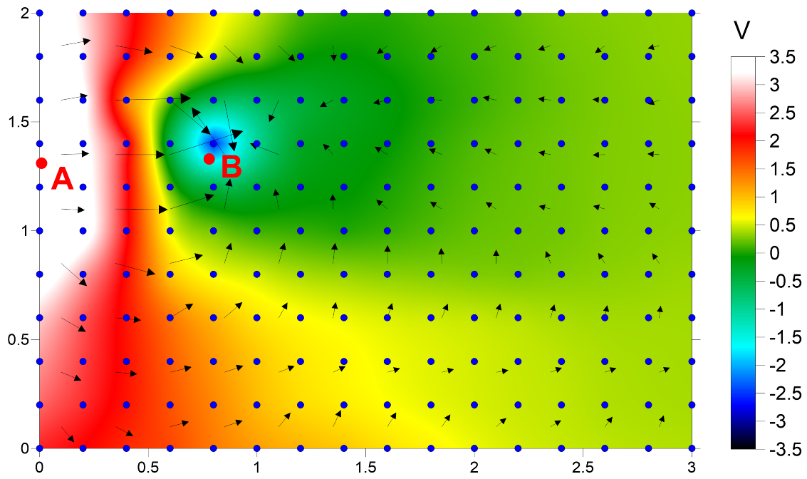
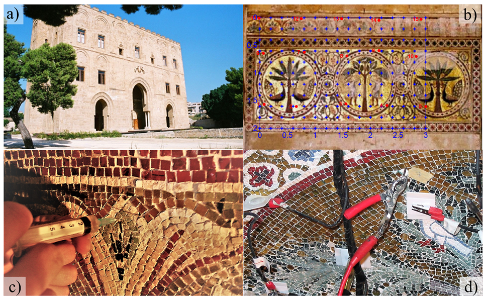
An interesting case history regards an ERT survey carried out on an ancient wall of the Zisa Palace in Palermo, which is located on the north-western coast of Sicily. The Zisa Palace is a 12th-century structure built towards the end of the Norman reign, when the Norman–Arab style of architecture reached the peak of its development and sophistication. It was intended as a summer residence for the Norman King William I of Sicily. The Zisa Palace is a rectangular building with a front façade subdivided by three arches (Figure 17a). The central arch is the main entrance, where an inner archway leads into the central main room, called the “Fountain Room”, supported by twin marble columns. The “Fountain Room” is the most elaborately decorated room; the niches are decorated with “muqarnas” (Arabic stalactite roof vaultings) and a precious mosaic covers the main wall (Figure 17b). Unfortunately, recent studies for the restoration of the mosaic have shown that a few tesserae are about to detach because of the high humidity in the wall. The presence of moisture in the wall was at first ascribed to water upwelling from the subsoil. This justification, however, seemed improbable, as the mosaic is located about 3.5 m above the floor of the hall and no moisture was present in the lower part of the fountain below the mosaic. For this reason, during the restoration work a 3D ERT survey was carried out on the mosaic in order to solve this problem and detect the source of the moisture. Apparent resistivity measures were acquired using the Maximum Yield Grid array (Figure 12; [21,126]. A regular grid of 11 × 16 mono-use silver electrocardiogram electrodes (Figure 17d) was placed on a 2 m × 3 m section of the mosaic surface of the wall (Figure 17b). These electrodes were used only as potential electrodes. Only 15 very small nails were used as current electrodes, and were located in available interstices among the tesserae of the mosaic by inserting them into small drilled perforations 2 mm in diameter. This assured a very low impact on the mosaic structure, although as a consequence the resulting distribution of the current electrodes was not perfectly regular. Small amounts of water and conductive gel were injected into the perforations before inserting the nails (Figure 17c) in order to enhance the electrolytic conduction around the electrodes and the resulting current flow. The use of an MYG array together with the irregular disposition of the current electrodes (Figure 17d) was done with the aim of greatly decreasing the invasivity of the survey. Moreover, this approach avoided significant loss of resolution with respect to other arrays. In total, 38 different current dipoles were used in the horizontal, vertical, and diagonal directions, and a total of 6612 apparent resistivity measurements were collected when selecting the potential dipoles as close as possible to the hypothetical current lines in the medium.
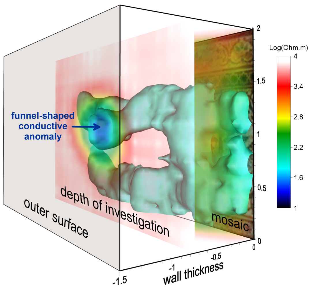
The generated 3D inverse model (Figure 18) extended down to about 70 cm inside the wall, which was about half its thickness. Stones of calcarenite, a sedimentary permeable rock highly used in Sicily as a building stone, constitute the walls of the palace. Hence, it can be hypothesized that variations in the resistivity distribution are due to differences in moisture content in the wall. However, 3D ERT showed a superficial conductive anomaly that decreased in lateral extension with depth, forming a funnel shape, and which seemed to originate in an area inside the wall in close correspondence to the water pipe of the fountain at about 1 m below the beginning of the mosaic in the vertical direction. This conductive anomaly was interpreted as a water accumulation zone inside the masonry. Although the fountain has not collected water for decades, this water accumulation could be due to a clogged water pipe in the ancient system, which might have collected water from the roof and become clogged closer the fountain. The deep high-resistivity volumes surrounding the accumulation zone can be explained by the difference between the two exposed sides of the wall; the internal surface is covered by the mosaic, which obstructs moisture evaporation, while the external one has no mosaic and is exposed to the wind and sun.

5. Aerial Archaeology

Remote Sensing Aerial Archaeology is a sub-field of Remote Sensing. In recent years it has enjoyed broad technological development, providing strong supporting for related studies in landscape archaeology by allowing researchers to achieve excellent results in non-destructive ways. It is used to detect surface and subsurface features not immediately visible from a ground-level perspective, as a means of locating and verifying ancient remains and studying their relations with their surrounding territory, and to determine the exact location of ancient structures or sites as well as pathways and connections between these sites. In addition, it is helpful in determining the location of natural resources, which can reveal why a community may have settled in a specific area.
More recently, in the wake of improvements in remote sensing technology, information has been collected by capturing the reflections and absorptions of both visible light and of other electromagnetic wavelengths, such as ultraviolet, infrared (e.g., NIR, MIR, and thermal), and microwave by using passive and active sensors such as multi-spectral scanners and radars [158]. UAS (Unmanned Aircraft System), commonly called “drones”, have become widely available for many disciplines, offering multiple advantages over traditional field work or high-altitude remote sensing techniques. UAS can be equipped with different high-definition cameras and sensors to offer several mapping applications in photography, archaeology, geology, geography, meteorology, agriculture, and forestry. Moreover, they enable reconstruction of three-dimensional models of inaccessible or unsafe outcrops. They can bridge the spatial scale gap in mapping between manual field techniques and high-altitude airborne remote sensing methods. Computer vision algorithms such as Structure from Motion (SfM) and Dense Image Matching (DIM), often included in the classical photogrammetric procedures and the integration of sensors and data, have provided comprehensive tools for managing all aspects of spatial information science. DSM and digital orthophotos enable information about structures and terrain to be extracted.

5.1. UAS Photogrammetry

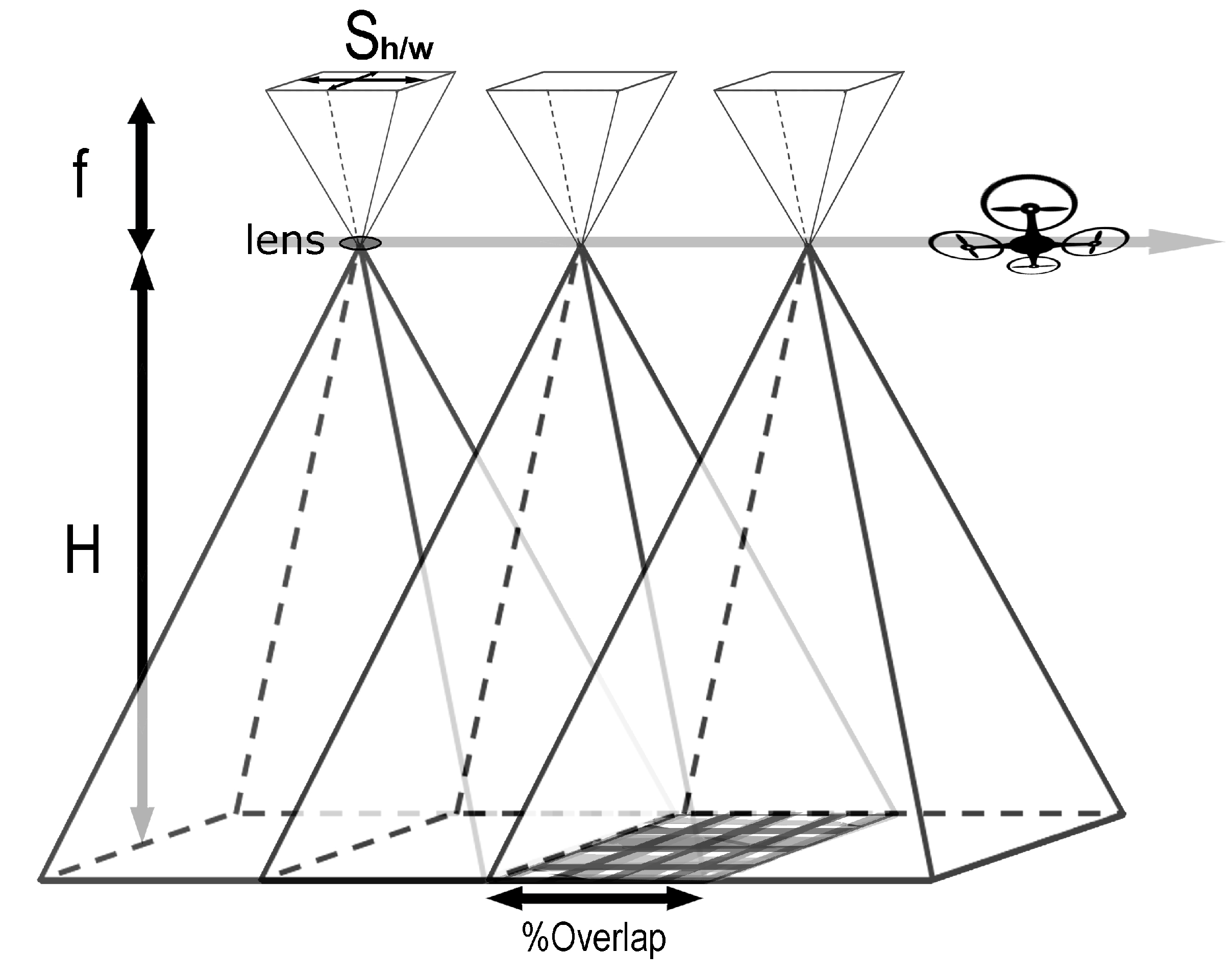
A UAS can be controlled by a computer and fly autonomously, be remotely controlled by a navigator on the ground, or operate semi-autonomously in a combination of both capabilities. A UAS remote sensing system consists of four main components: aircraft with sensor(s) for data acquisition; remote control for the entire craft; GPS for navigation; and an inertial measurement unit (IMU) for altitude measurement. Fixed or rotary-wing flight parameters include flying height above the highest point of the site, flight speed, focal length, and shooting rate; these define the image resolution, photo footprint, and overlap between photos [159]. The right choice of flight parameters is a compromise between flying height and focal length. These two parameters depend on technological constraints such as the battery range of the UAS and the data storage capability. GPS/IMU direct georeferencing adds additional control of each camera’s focal point and of the orientation for every photo. It is important to ensure that the ratio of stereoscopic baseline to fly height is between 1/6 and 1/2 to ensure better intersection of homolog rays. Figure 19 shows the photogrammetric parameters in a series of shots for a single flight line. The ground resolution is the minimum distance at which two goals can be distinguished in the image. A helpful formula for calculating the ground resolution R is provided by (1) and (2), considering the not perfectly square camera sensor:
R h = F l i g h t H e i g h t S e n s o r h e i g h t F o c a l l e n g t h I m a g e h e i g h t
R w = F l i g h t H e i g h t S e n s o r w i d t h F o c a l l e n g t h I m a g e w i d t h

5.2. Aerial Triangulation

The aerial triangulation theory in photogrammetry is based on the principle of bundle adjustment [160]. This method allows the coordinates of a 3D object to be determined and calculated using photographs exposed from different positions covering the same object. Figure 20a shows the aerial acquisition process and Figure 20b depicts three photos in a single flight line, with straight lines linking a point on the ground with its corresponding pixels in each picture. In order to complete an aerial survey, it is necessary to extend the picture including other flight lines, called “side-lapping”, to cover the overlapping whole area. This aero-triangulation enforces the collinearity condition and the redundant intersection of image rays in “object space” creates a bridge from one photo to the next, thereby reducing the amount of ground control needed to reconstruct the exterior orientation for every photo. In order to perform bundle adjustment and orientation of the entire UAS model in an absolute geo-reference system, it is necessary to employ ground control points (GCPs) identified by “markers” scattered across the entire investigated area. These ground control points are a key part of aerial triangulation. The calculation method uses rigorous collinearity equations in photogrammetry to establish the object–UAS image relationship. The UAS camera must be rigorously calibrated, and the lens distortion needs to be considered. The coordinates are calculated using the spatial intersections. Finally, image dense matching is used to generate 3D point clouds and DSM. Recently, several conventional photogrammetric software packages have been developed for processing of UAS image data, e.g., Photoscan pro [161], Pix4d Mapper, Drone Deploy, and Propeller Network. These bring together knowledge from computer vision and traditional photogrammetry using an approach commonly called ‘‘structure from motion’’ [162]. In the structure from motion technique, the corresponding points in the original images are first detected, then the three-dimensional positions of these points are calculated as a point cloud. Polygons are created based on the point cloud and interpolated to produce a DSM. The pixel values of each image can be projected onto the computed polygon mesh to create an Orthomosaic.

5.3. Photogrammetric Aerial Survey

A non-invasive investigation based on an aerial survey was carried out to detect structural failures in the walls and foundations at the Selinunte Acropolis, located in south-western Sicily, seeking to identify ancient collapses along the defensive northern fortifications. The Selinunte Archaeological Park is today the most extensive archaeological area in Europe, covering 270 hectares; it includes temple architecture (on the eastern hill and inside the acropolis), a necropolis, and impressive fortifications surrounding the acropolis. In this study, a DJI Phantom III Professional quadcopter drone with a 12-megapixel mounted digital camera was used. Before conducting drone mapping, we planned the flight paths and areas for each flight mission. For most missions, the drone was set to take aerial photographs in “autopilot mode”, with the camera facing directly downwards for hilly terrain. A few surveys were conducted with the camera mounted 45° sideways to enable high-quality capture of data from cliff faces. We selected a 75% forward and sideways overlap of images. We carried out more than six flight missions, capturing a total of 1300 pictures, and mapped an area of about 0.3 km2 in total, with a focus on the mapping of the northern gate and defensive walls. The acquisition of field data required the determination of fifteen GCPs distributed within the defined area.
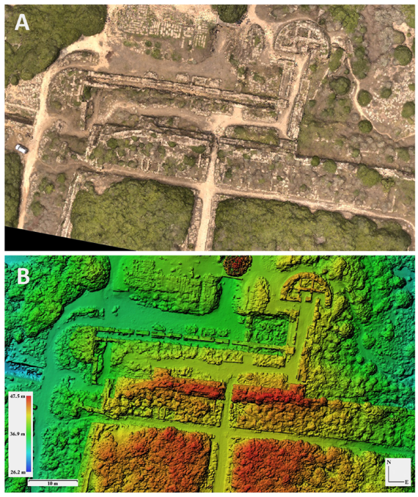
Several software packages are available for creating digital surface models and orthomosaics from drone-captured photographs. In this study, we used Agisoft Photoscan software, which applies SfM photogrammetry to process the raw images captured by the drone. Agisoft Photoscan is commercial software that creates 3D content from still images. It can interpolate digital images to create high-resolution scaled and georeferenced three-dimensional models. Tests have revealed that Photoscan excels in processing aerial frame imagery, which makes it very suitable for studies such as this one. The first results obtained through the applied procedures were the created orthophotos, which are significant for bi-dimensional redesign, along with the creation of a 3D polygonal mesh, which is helpful in rebuilding the archaeological site in a three-dimensional a virtual environment. Figure 21 shows the final dense cloud model and the high-resolution DSM derived from aerial photographic mapping of the northern acropolis fortifications. The resulting high-resolution DSM is quite detailed, and the single elements of the wall are recognizable, permitting a deep morphological analysis. Profiles extracted from these models allow the accurate measurement of the lateral displacement of masonry portions or block stones as well as the depth and spatial organization of the penetrative fractures. In particular, it allows features which are difficult or impossible to access in the field to be analyzed.

5.4. Aerial Infrared Thermography

Aerial thermography has seen relatively little use in archaeological contexts, although it has great potential for detecting anthropogenic anomalies. Archaeological features can have thermal signatures that contrast strongly with the surrounding matrix, and which can consequently be visually identified in thermal images. Thermal cameras record heat in the form of thermal infrared radiation (TIR). Heat energy moves by conduction, convection, and radiation, and there are three ways in which the radiant energy striking an object can be dissipated, namely, absorption, transmission, and reflection. Any object at a temperature above absolute zero (−273.15 °C or 0 K) emits infrared radiation (below red). The infrared spectrum range can be further subdivided into near-infrared (0.8–1.5 μm), short-wavelength infrared (1.5–2.5 μm), mid-wavelength infrared (2.5–8 μm), and far-wavelength infrared (8–14 μm). The intensity of the infrared radiation emitted by objects is a function of the temperature of their material and its emissivity. A material’s emissivity is the ability of its surface to emit energy by radiation relative to a black body (in which both the transmissivity and reflectivity are null and the emissivity is unity). For surface temperature estimation, down-welling radiation can be measured with a thermal sensor. Atmospheric conditions, viewing angle, altitude, the timing of image acquisition, haze, and cloud cover conditions can influence thermal data collected by aerial platforms. Thus, these conditions should be carefully monitored when acquiring thermal images. The performance of the thermal camera, relative humidity, shooting angle, shooting distance, and other emitted and reflected thermal radiation sources should be evaluated as well. In addition, a clear understanding of the thermal properties of the soil is necessary in order to understand the behaviour of heat within the soil itself [163].
A material with high thermal inertia, such as water, is slow to heat up or cool down. Sand, on the other hand, heats much more quickly in the sun and cools just as quickly at night due to its lower thermal inertia. Thermal inertia, as shown by the above equation, is another way to describe the complex relationship between thermal conductivity, volumetric specific heat, and diffusivity. It is an extremely useful value for estimating the potential strength of anomalies in different contexts. On account of their different thermal properties, archaeological features do not all show the same visible thermal signatures; subterranean features heat and cool at separate rates depending on their thermal inertia, while a long stretch of stable weather conditions might allow time for all features and layers to reach equal temperatures. Thermography must be carried out while the temperatures of materials are adjusting and differences are at their maximum [43]. The value of dampening effect depends on the thickness, thermal diffusivity, and thermal conductivity of the particular soil layer. The homogeneous or heterogeneous composition of the soil layer plays an important role; indeed, inclusions can be helpful if they represent surface reflections of deep archaeological features, or if they have the opposite effect of overwhelming and masking subsurface features. These are strongly affected by diurnal variations, and are most visible in the afternoon [43].
During the year, vegetation growth, humidity, plowing, and transient heat flux variations create excessive noise, meaning that anomalies are obscured [43]. In certain cases, the vegetation acts as a screen that obscures the thermal response of any features below, while in other cases subterranean features may affect the growth of vegetation over them, either positively or negatively [164]. Porous soils are less dense, and generally have lower heat capacity, although this property is easily affected by moisture content [165,166,167,168,169]. Soil water content can improve the thermal conductivity of soils with high porosity. In dry soil, low-conducting air fills the space between soil particles, limiting heat transfer [169].

5.5. Thermal Infrared Aerial Survey

Aerial thermal surveys have been carried out over a small area of the Greek archaeological site of Kamarina in southern Sicily, seeking to support hypotheses derived from historical and archaeological studies [8]. Kamarina was an important Greek colony, beginning with its foundation by Syracuse in 599 BC. Archaeological excavations carried out from the twentieth century onward have uncovered only limited portions of the site, and a number of remarkable buildings have yet to be found. The survey carried out in the study area aimed to address these issues and support future archaeological investigations.
The TIR sensor software allows the extraction of the temperature matrix of each frame in ASCII format. This extraction was conditioned by the desired overlap, which in this case was established at 80%. Thermal data were processed using a GIS platform. The first step in data processing consisted of preparing the images associated with the temperature matrix for the orientation process. Temperature values were scaled to 256 digital levels using a linear transformation, producing images in 8-bit color-scale. This thermal raster dataset was georeferenced by assigning the UTM/WGS84 coordinate system, and a thermally orthorectified mosaic with a pixel size of 0.5 cm was generated. The orthomosaic of the thermal infrared imagery is shown in Figure 22.

5.6. Magnetic Aerial Survey

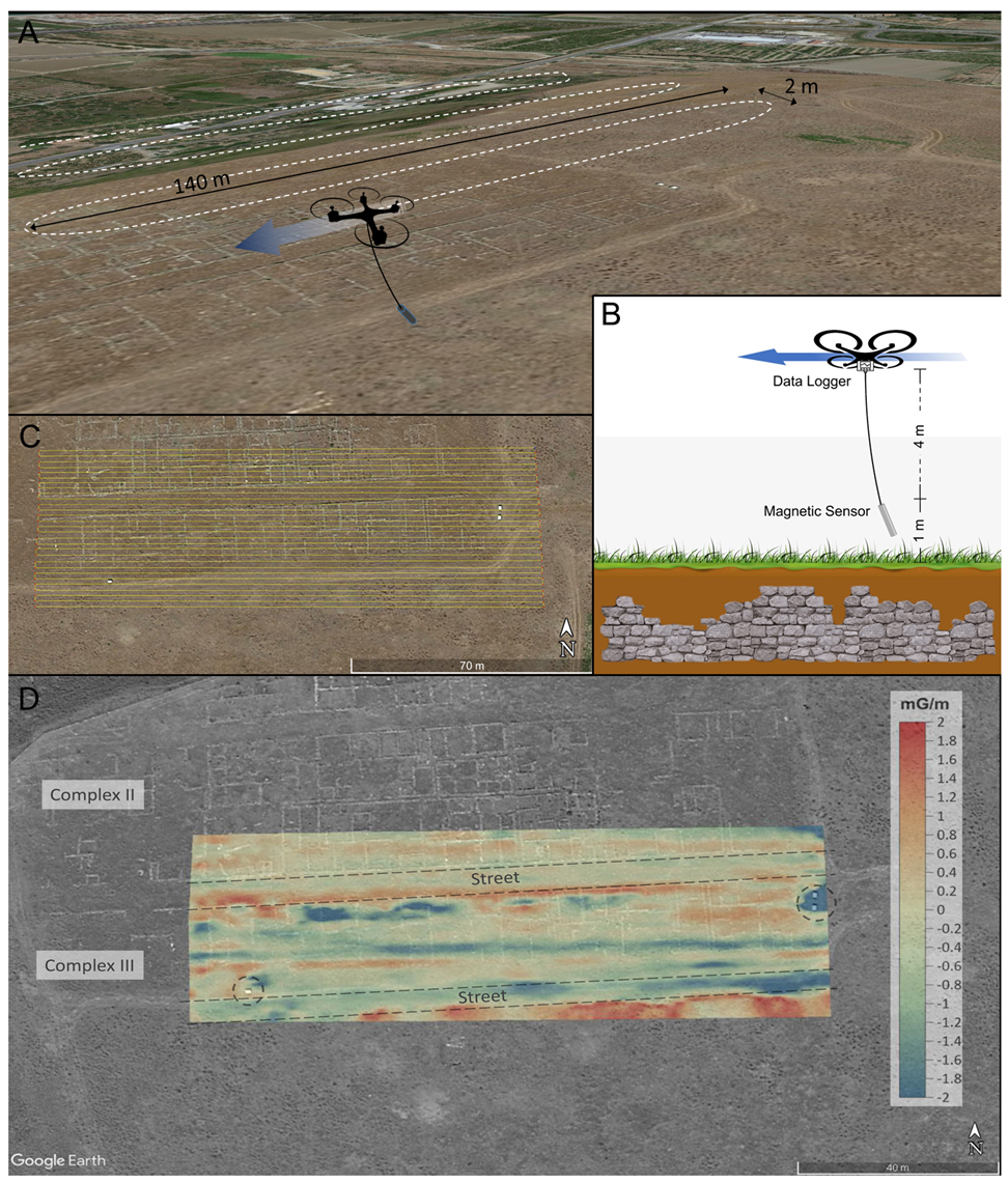
In recent years, the extensive development of Unmanned Aircraft Systems (UAS) have partially filled the large gap between airborne and ground-based measurements. In particular, the use of a UAS can make it faster, more reliable, and even safer to perform magnetic observations, overcoming limitations of traditional ground-based surveys such as difficulty of access, uneven terrain, and the presence of obstacles. Moreover, their cost much less than previous airborne surveys. Of course, the physical principles and the general criteria behind UAS magnetic surveying for archaeological/cultural heritage purposes are the same as those introduced in Section 2.
The magnetic applications for UAS have seen great expansion in recent years [170,171,172,173,174,175,176,177,178,179]. Previous research has sometimes focused exclusively on the technological features of the devices, overlooking the issue of data quality, which influences the magnetic anomaly detection capability [180]. A detailed review of these devices is beyond of the scope of the present article; here, we only recall the variety of UAS platforms (unmanned helicopters, muti-rotor UAS, fixed-wing UAS) used with magnetic sensors (the fluxgate magnetometer being the most widely employed), mounting systems (loosely or rigidly anchored to the vehicle; in front, below, or at the rear), and interference compensation (passive or active). Interested readers may refer to [181] for a complete review). The main source of interference is represented by the UAS itself. Placing the magnetic sensor farther away from the UAS by means of a cable or rope is an effective way to reduce or even eliminate this interference; such approaches are referred to as “passive”. The alternative, “active” suppression of interference, involves characterization of the interference source and implementation of compensation either in real time or during post-processing. In particular, suppression of this interference is decisive in applications related to archaeology, as the relevant magnetic anomalies are often subtle and can be easily concealed within the magnetic noise. Moreover, because of the lack of robust interpretation methods for UAS-based magnetic surveys, research on the processing and interpretation of UAS magnetic data is relatively rare and quite difficult [181].
As a case study, we report the survey performed by [177] in an archaeological site where certain archaeological features are unearthed and clearly visible while other parts are buried beneath a shallow subsurface. The test site was the Himera Archaeological Park in Sicily, Italy, which serves as a representation of the remaining portions of the ancient Greek city of Himera [182]. This ancient town was founded around 648 BC, close to the mouth of the Northern Imera River. The town is divided into two separate regions: the lower town near the river’s mouth, and the upper town on the southern hill. Only a few geophysical investigations have been carried out at this archaeological site in the past [89,183]. Extensive excavations of the upper town have already uncovered several ancient artefacts. The higher town was selected as the test location. The survey was conducted following a track oriented E–W. To the west of Athena’s Temenos, three previously uncovered housing complexes are partially covered by the first area. The archaeological elements at this location are structured in an orthogonal pattern, with the primary features (such as roadways, foundations, and walls) aligned ENE–WSW (Figure 23). The flight plan stretches laterally into unexplored areas to find fresh findings while partially covering two uncovered housing complexes to test the system on known results. Although the UAS travels at a fixed absolute altitude, the distance from the ground may change because the landscape is not completely flat. Gradiometric measurements were carried out by repeating both surveys at a higher elevation (+1 m). According to the UAS controlling software, which does not permit finer control in the vertical position, this figure corresponds to the smallest vertical step allowed. Gradiometry has several advantages, including the fact that measurement is not affected by temporal fluctuations and that it can isolate signals from shallow sources such as archaeological features, reducing sensitivity to deeper larger-scale sources [170].
The map of the residual anomaly shows a pattern which is in agreement with the archaeological features. Although it is not possible from the map of residual anomalies to accurately detect the archaeological structures present in the area, anomalies attributable to buried anthropogenic structures are highlighted. Both positive and negative anomalies are stretched along the ∼E–W direction that corresponds to the main wall foundations beside the 6 m wide roads (Figure 24). Secondary anomalies mark a number of the minor wall foundations in the ∼N–S direction, i.e., complex II in Figure 24. Anomalies with a similar arrangement are recognizable in the southernmost stripe of the surveyed area, where the site has not been excavated yet. Finally, in the easternmost portion of the site, the clear anomaly is due to a pair of metal boards, which are visible in the aerial photograph.
The device presented in this work integrated a fluxgate magnetometer with a UAS platform. This system enables a broad range of applications. The operational performance has been tested in the field; in this case, from among the possible applications we selected one of the most extreme cases, namely, archaeological prospection, where anomalies are usually very subtle. For this test, in particular, the system presents several unavoidable limitations, though these are somewhat compensated for by the other advantages of UAS magnetometry. In archaeological magnetic prospection, the sensor must be located as close to the ground as possible (several tens of cm), and the distance for gradiometry should be conveniently short.
The UAS system described above allows a minimum distance of the sensor from the ground of about 2 m and a distance for gradiometry equal to 1 m. Obviously, this arrangement is not optimized for the detection of superficial archaeological structures of small dimensions, such as wall structures, which are typically a few tens of centimetres in size. However, this system should be able to highlight archaeological features, even at greater depths, and highlight the main structures, such as ancient roads, for which dimensions reach at least a few meters. Thus, although it suffers from the low resolution of archaeological features, it is nevertheless possible to recognize the main alignments marked by anomalies with amplitudes <1.0 mG. The advantage of UAS magnetometry relies on the high density of measurements, which avoids missing short-wavelength anomalies, and on the time efficiency of the survey method. In fact, large areas can be surveyed in a very short time compared with more traditional survey methods. The ability to survey large areas that require in-depth and detailed investigation provides UAS magnetometry with its great potential in archaeological contexts. Although the system does not allow a high degree of resolution in the restitution of buried archaeological structures, it must be emphasized that the ability to identify and map archaeological structures depends on the contrast of the anomalies they produce. For this reason, certain sites are easier to investigate than others. Furthermore, considering the results of the system test on an archaeological site, it can reasonably be assumed that the system is more suitable for fields of application where the expected anomalies are of greater intensity and/or greater scale; examples of possible field applications might include mining exploration, the detection of buried metal objects, or even mapping the magnetic structure of the subsoil.

6. Conclusions

The contribution of geophysical techniques and their integration is fundamental for identification, preservation, and enhancement in the Archaeology and Cultural Heritage fields. The application of these methodologies is often decisive in solving management issues through a multidisciplinary approach, resulting in better knowledge and resolution. This review of the most widely used geophysical methodologies in archaeology and cultural heritage conservation summarizes the relevant theory, tools, and data processing techniques, and presents a number of representative field cases.
Each of the techniques described is characterized by both strong points and drawbacks affecting imaging capability or operation in the field (Figure 25). However, all of these methods are mutually compensatory. There is always at least one technique that provides the highest performance on each of the features listed in Figure 25. Therefore, it is always possible to find a specific combination of techniques (two or even more) that are able to address a particular problem in the best possible way. Moreover, multidisciplinary investigations can reduce the cost and time of an archaeological survey by providing indications of the positions and shapes of archaeological features. Consequently, excavations can be undertaken in limited sectors of the analyzed area without introducing substantial modification or disturbance to the territory.
The use of all available archaeological data (e.g., estimated depth of targets, extent and presumed location of structures, thickness, nature of archaeological and geological strata) as a priori information is fundamental for finding a well-constrained solution of the inverse geophysical problem, as well as for the joint interpretation of different geophysical models and estimating the reliability of interpretation and conclusive development of the archaeo-geophysical model. The latter is necessary in order to guide appropriate choices when seeking to preserve archaeological remains and plan further excavations.
Geophysical techniques were originally designed to measure various physical properties of the subsurface soils and rocks at scales from several meters to several kilometers; however, the scale of heritage features are often closer to centimeters, or at most a few meters. Thus, while certain methods and instrumentation approaches have been adapted to archaeological sites, others are of marginal or negligible value. In this review, we have discussed those geophysical techniques most suited to this adaptation and which are consequently the most widely used in Archaeology and Cultural Heritage contexts. These three techniques, namely, Magnetometry, Electrical Resistivity Tomography, and Ground Penetrating Radar, are favored for their integrated use, further supported by remote sensing techniques and UAS; they provide the ability to increase the resolution and precision of measurements and to correctly georeference the results. This branch of archaeogeophysics is rapidly evolving, and is proving to be of increasing use to the archaeological community.
Many efforts have been made to reduce the invasiveness of geophysical methods and adapt them to closed or limited environments. These include the implementation of less invasive sensors in order to preserve the integrity of the cultural assets being studied. At the same time, an increase in the amount of data obtained in the acquisition phase is necessary, often in conjunction with the integration of different methods or supported by a high-resolution digital surface model, in order to significantly increase the resolution of interpretative models and limit their uncertainty. As demonstrated by the progress gained over the last decades, all these geophysical techniques can certainly be expected to continue to improve; as such, what scenario can be envisaged for the near future?
The devices used in the methods described in this review can be expected to see gains in terms of the sensitivity, precision, effectiveness, and reliability of the acquired data. Increases in computational power might deliver faster data processing, in turn providing higher-resolution imaging and more precise geophysical models. The value of geophysics for cultural heritage should increase as well, thanks to the growing interest in this topic and in the care afforded to historical patrimony more generally.
For all these reasons, in the future we anticipate the broader geophysics discipline to represent an even more fundamental tool in the study, preservation, and promotion of cultural heritage.

Author Contributions

Conceptualization, R.M., P.C., A.P., S.S. and C.B.; methodology, R.M., P.C., A.P. and S.S.; software, R.M., P.C., A.P. and S.S.; validation, R.M., P.C., A.P. and S.S.; formal analysis, R.M., P.C., A.P., S.S. and C.B.; investigation, R.M., P.C., A.P. and S.S.; resources, R.M., P.C. and A.P.; data curation, R.M., P.C., A.P. and S.S.; writing—original draft preparation, R.M., P.C., A.P., S.S. and C.B.; writing—review and editing, R.M., S.S. and C.B.; visualization, R.M., P.C., A.P., S.S. and C.B.; supervision, R.M. All authors have read and agreed to the published version of the manuscript.

Funding

This research received no external funding.

Institutional Review Board Statement

Not applicable.

Informed Consent Statement

Not applicable.

Data Availability Statement

Data can be obtained upon request from the corresponding author.

Conflicts of Interest

The authors declare no conflict of interest.

References

  1. Batayneh, A.T. Archaeogeophysics–archaeological prospection—A mini review. J. King Saud-Univ. Sci. 2011, 23, 83–89. [Google Scholar] [CrossRef] [Green Version]
  2. Deiana, R.; Leucci, G.; Martorana, R. New perspectives on geophysics for archaeology: A special issue. Surv. Geophys. 2018, 39, 1035–1038. [Google Scholar] [CrossRef] [Green Version]
  3. Barone, P.M.; Ruffell, A.; Tsokas, G.N.; Rizzo, E. Geophysical Surveys for Archaeology and Cultural Heritage Preservation. Heritage 2019, 2, 2814–2817. [Google Scholar] [CrossRef] [Green Version]
  4. Cozzolino, M.; Di Giovanni, E.; Mauriello, P.; Piro, S.; Zamuner, D. Geophysical Methods for Cultural Heritage Management; Springer: Berlin/Heidelberg, Germany, 2018. [Google Scholar]
  5. El-Qady, G.; Metwaly, M. Archaeogeophysics: State of the Art and Case Studies; Springer: Berlin/Heidelberg, Germany, 2018. [Google Scholar]
  6. Brizzolari, E.; Ermolli, F.; Orlando, L.; Piro, S.; Versino, L. Integrated geophysical methods in archaeological surveys. J. Appl. Geophys. 1992, 29, 47–55. [Google Scholar] [CrossRef]
  7. Urbini, S.; Cafarella, L.; Marchetti, M.; Chiarucci, P.; Bonini, D. Fast geophysical prospecting applied to archaeology: Results at «Villa ai Cavallacci»(Albano Laziale, Rome) site. Ann. Geophys. 2007, 50, 291–299. [Google Scholar] [CrossRef]
  8. Scudero, S.; Martorana, R.; Capizzi, P.; Pisciotta, A.; D’Alessandro, A.; Bottari, C.; Di Stefano, G. Integrated Geophysical Investigations at the Greek Kamarina Site (Southern Sicily, Italy). Surv. Geophys. 2018, 39, 1181–1200. [Google Scholar] [CrossRef]
  9. Martinho, E.; Dionísio, A. Main geophysical techniques used for non-destructive evaluation in cultural built heritage: A review. J. Geophys. Eng. 2014, 11, 053001. [Google Scholar] [CrossRef]
  10. Ekinci, Y.L.; Özyalın, Ş.; Sındırgı, P.; Balkaya, Ç.; Göktürkler, G. Amplitude inversion of the 2D analytic signal of magnetic anomalies through the differential evolution algorithm. J. Geophys. Eng. 2017, 14, 1492–1508. [Google Scholar] [CrossRef]
  11. Doll, W.E.; Miller, R.D.; Bradford, J. The emergence and future of near-surface geophysics. Lead. Edge 2012, 31, 684–692. [Google Scholar] [CrossRef]
  12. Maher, B.A.; Taylor, R.M. Formation of ultrafine-grained magnetite in soils. Nature 1988, 336, 368–370. [Google Scholar] [CrossRef]
  13. Magiera, T.; Strzyszcz, Z.; Kapicka, A.; Petrovsky, E.; MAGPROX TEAM. Discrimination of lithogenic and anthropogenic influences on topsoil magnetic susceptibility in Central Europe. Geoderma 2006, 130, 299–311. [Google Scholar] [CrossRef]
  14. Nex, F.; Remondino, F. UAV for 3D mapping applications: A review. Appl. Geomat. 2014, 6, 1–15. [Google Scholar] [CrossRef]
  15. Cosentino, P.; Capizzi, P.; Fiandaca, G.; Martorana, R.; Messina, P. Advances in microgeophysics for engineering and cultural heritage. J. Earth Sci. 2009, 20, 626–639. [Google Scholar] [CrossRef]
  16. Cosentino, P.; Capizzi, P.; Martorana, R.; Messina, P.; Schiavone, S. From geophysics to microgeophysics for engineering and cultural heritage. Int. J. Geophys. 2011. Available online: https://www.hindawi.com/journals/ijge/2011/428412/ (accessed on 10 December 2022). [CrossRef] [Green Version]
  17. Masini, N.; Soldovieri, F. Integrated non-invasive sensing techniques and geophysical methods for the study and conservation of architectural, archaeological and artistic heritage. J. Geophys. Eng. 2011, 8, E01. [Google Scholar] [CrossRef]
  18. Sala, J.; Linford, N. Processing stepped frequency continuous wave GPR systems to obtain maximum value from archaeological data sets. Near Surf. Geophys. 2012, 10, 3–10. [Google Scholar] [CrossRef]
  19. Bottari, C.; Capizzi, P.; Martorana, R.; Azzaro, R.; Branca, S.; Civico, R.; Fucile, M.; Pecora, E. Diagnostic Multidisciplinary Investigations for Cultural Heritage at Etna Volcano: A Case Study from the 1669 Eruption in the Mother Church at the Old Settlement of Misterbianco. Remote Sens. 2022, 14, 2388. [Google Scholar] [CrossRef]
  20. Capizzi, P.; Martorana, R.; Messina, P.; Cosentino, P. Geophysical and geotechnical investigations to support the restoration project of the Roman ‘Villa del Casale’, Piazza Armerina, Sicily, Italy. Near Surf. Geophys. 2012, 10, 145–160. [Google Scholar] [CrossRef]
  21. Casas, A.; Cosentino, P.L.; Fiandaca, G.; Himi, M.; Macias, J.M.; Martorana, R.; Muñoz, A.; Rivero, L.; Sala, R.; Teixell, I. Non-invasive geophysical surveys in search of the Roman Temple of Augustus under the Cathedral of Tarragona (Catalonia, Spain): A case study. Surv. Geophys. 2018, 39, 1107–1124. [Google Scholar] [CrossRef] [Green Version]
  22. Capozzoli, L.; Mutino, S.; Liseno, M.G.; De Martino, G. Searching for the History of the Ancient Basilicata: Archaeogeophysics Applied to the Roman Site of Forentum. Heritage 2019, 2, 1097–1116. [Google Scholar] [CrossRef] [Green Version]
  23. Martorana, R.; Capizzi, P. Seismic and non-invasive geophysical surveys for the renovation project of Branciforte Palace in Palermo. Archaeol. Prospect. 2020. Available online: https://onlinelibrary.wiley.com/doi/10.1002/arp.1781 (accessed on 10 December 2022). [CrossRef]
  24. Costanzo, A.; Pisciotta, A.; Pannaccione Apa, M.I.; Bongiovanni, S.; Capizzi, P.; D’Alessandro, A.; Falcone, S.; La Piana, C.; Martorana, R. Integrated use of unmanned aerial vehicle photogrammetry and terrestrial laser scanning to support archaeological analysis: The Acropolis of Selinunte case (Sicily, Italy). Archaeol. Prospect. 2021, 28, 153–165. [Google Scholar] [CrossRef]
  25. Caldeira, B.; Oliveira, R.J.; Teixidó, T.; Borges, J.F.; Henriques, R.; Carneiro, A.; Peña, J.A. Studying the construction of floor mosaics in the Roman Villa of Pisões (Portugal) using noninvasive methods: High-resolution 3D GPR and photogrammetry. Remote Sens. 2019, 11, 1882. [Google Scholar] [CrossRef] [Green Version]
  26. Biscarini, C.; Catapano, I.; Cavalagli, N.; Ludeno, G.; Pepe, F.; Ubertini, F. UAV photogrammetry, infrared thermography and GPR for enhancing structural and material degradation evaluation of the Roman masonry bridge of Ponte Lucano in Italy. NDT E Int. 2020, 115, 102287. [Google Scholar] [CrossRef]
  27. Masini, N.; Sogliani, F.; Sileo, M.; Abate, N.; Danese, M.; Vitale, V.; Lasaponara, R.; Piro, S. Fusion and integration of heterogeneous close range remote sensing and geophysical data. The case of Grumentum. In Proceedings of the Journal of Physics: Conference Series; IOP Publishing: Bristol, UK, 2022; Volume 2204, p. 012018. [Google Scholar]
  28. Zhao, Y.; Ling, C.; Zhang, K.; Gao, Y.; Sun, B.; Wang, X. Detection of hidden mining-induced ground fissures via unmanned aerial vehicle infrared system and ground-penetrating radar. Int. J. Rock Mech. Min. Sci. 2022, 160, 105254. [Google Scholar] [CrossRef]
  29. Nabighian, M.N.; Grauch, V.; Hansen, R.; LaFehr, T.; Li, Y.; Peirce, J.W.; Phillips, J.D.; Ruder, M. The historical development of the magnetic method in exploration. Geophysics 2005, 70, 33ND–61ND. [Google Scholar] [CrossRef]
  30. Kvamme, K.L. Magnetometry: Nature’s gift to archaeology. In Remote Sensing in Archaeology: An Explicitly North American Perspective; The University of Alabama Press: Tuscaloosa, Alabama, 2006; pp. 205–233. [Google Scholar]
  31. Gaffney, C. Detecting trends in the prediction of the buried past: A review of geophysical techniques in archaeology. Archaeometry 2008, 50, 313–336. [Google Scholar] [CrossRef]
  32. Fassbinder, J.W. Seeing beneath the farmland, steppe and desert soil: Magnetic prospecting and soil magnetism. J. Archaeol. Sci. 2015, 56, 85–95. [Google Scholar] [CrossRef]
  33. Garrison, E.G. Techniques in Archaeological Geology; Springer: Berlin/Heidelberg, Germany, 2016. [Google Scholar]
  34. Fedi, M.; Cella, F.; Florio, G.; Manna, M.L.; Paoletti, V. Geomagnetometry for archaeology. In Sensing the Past; Springer: Berlin/Heidelberg, Germany, 2017; pp. 203–230. [Google Scholar]
  35. Campbell, W.H. Introduction to Geomagnetic Fields; Cambridge University Press: Cambridge, UK, 2003. [Google Scholar]
  36. Love, J.J. Magnetic monitoring of Earth and space. Phys. Today 2008, 61, 31. [Google Scholar] [CrossRef] [Green Version]
  37. Hinze, W.J.; Von Frese, R.R.; Von Frese, R.; Saad, A.H. Gravity and Magnetic Exploration: Principles, Practices, and Applications; Cambridge University Press: Cambridge, UK, 2013. [Google Scholar]
  38. Becker, H. From nanotesla to picotesla—A new window for magnetic prospecting in archaeology. Archaeol. Prospect. 1995, 2, 217–228. [Google Scholar] [CrossRef]
  39. Smekalova, T.N.; Smekalov, S.L.; Voss, O.; Bevan, B.W. Magnetic Surveying in Archaeology: More than 10 Years of Using the Overhauser GSM-19 Gradiometer; Wormianum: Højbjerg, Denmark, 2008. [Google Scholar]
  40. Ciminale, M.; Loddo, M. Aspects of magnetic data processing. Archaeol. Prospect. 2001, 8, 239–246. [Google Scholar] [CrossRef]
  41. Bruniaux, G.; Mathé, V.; Lévêque, F.; Camus, A.; Ard, V. Data processing chain for high spatial resolution magnetic survey: Application on the Neolithic site of le Pontet (Charente-maritime, France). Archaeol. Prospect. 2018, 25, 3–16. [Google Scholar] [CrossRef]
  42. Chianese, D.; D’Emilio, M.; Di Salvia, S.; Lapenna, V.; Ragosta, M.; Rizzo, E. Magnetic mapping, ground penetrating radar surveys and magnetic susceptibility measurements for the study of the archaeological site of Serra di Vaglio (southern Italy). J. Archaeol. Sci. 2004, 31, 633–643. [Google Scholar] [CrossRef]
  43. Scollar, I.; Tabbagh, A.; Hesse, A.; Herzog, I. Archaeological Prospecting and Remote Sensing; Cambridge University Press: Cambridge, UK, 1990. [Google Scholar]
  44. Noviello, M.; Ciminale, M.; Del Gaudio, V.; Amoruso, L. Advances in reconstructing archaeological magnetic signals; An algorithm for filtering noise due to the ploughing effect. Archaeol. Prospect. 2017, 24, 87–99. [Google Scholar] [CrossRef]
  45. Roest, W.R.; Verhoef, J.; Pilkington, M. Magnetic interpretation using the 3-D analytic signal. Geophysics 1992, 57, 116–125. [Google Scholar] [CrossRef]
  46. Sheriff, S.D.; Macdonald, D.; Dick, D. Decorrugation, edge detection, and modelling of total field magnetic observations from a historic town site, Yellowstone National Park, USA. Archaeol. Prospect. 2010, 17, 49–60. [Google Scholar] [CrossRef]
  47. Cooper, G.R.; Cowan, D.R. Edge enhancement of potential-field data using normalized statistics. Geophysics 2008, 73, H1–H4. [Google Scholar] [CrossRef]
  48. Lee, M.; Morris, W.; Harris, J.; Leblanc, G. An automatic network-extraction algorithm applied to magnetic survey data for the identification and extraction of geologic lineaments. Lead. Edge 2012, 31, 26–31. [Google Scholar] [CrossRef]
  49. Stampolidis, A.; Tsokas, G.N. Use of edge delineating methods in interpreting magnetic archaeological prospection data. Archaeol. Prospect. 2012, 19, 123–140. [Google Scholar] [CrossRef]
  50. Ferreira, F.J.; de Souza, J.; de Barros e Silva Bongiolo, A.; de Castro, L.G. Enhancement of the total horizontal gradient of magnetic anomalies using the tilt angle. Geophysics 2013, 78, J33–J41. [Google Scholar] [CrossRef]
  51. Du, W.; Wu, Y.; Guan, Y.; Hao, M. Edge detection in potential filed using the correlation coefficients between the average and standard deviation of vertical derivatives. J. Appl. Geophys. 2017, 143, 231–238. [Google Scholar] [CrossRef]
  52. Zuo, B.; Hu, X.; Liu, S.; Geng, M. Delineation of overlapping magnetic field source boundaries with a 3-D multi-layer convolution model. J. Appl. Geophys. 2018, 150, 74–83. [Google Scholar] [CrossRef]
  53. Cooper, G. Forward modelling of magnetic data. Comput. Geosci. 1997, 23, 1125–1129. [Google Scholar] [CrossRef]
  54. Quesnel, Y.; Langlais, B.; Sotin, C.; Galdéano, A. Modelling and inversion of local magnetic anomalies. J. Geophys. Eng. 2008, 5, 387–400. [Google Scholar] [CrossRef]
  55. Bott, M. Two methods applicable to computers for evaluating magnetic anomalies due to finite three dimensional bodies. Geophys. Prospect. 1963, 11, 292–299. [Google Scholar] [CrossRef]
  56. Talwani, M. Computation with the help of a digital computer of magnetic anomalies caused by bodies of arbitrary shape. Geophysics 1965, 30, 797–817. [Google Scholar] [CrossRef]
  57. Li, Y.; Oldenburg, D.W. 3-D inversion of magnetic data. Geophysics 1996, 61, 394–408. [Google Scholar] [CrossRef]
  58. Herwanger, J.; Maurer, H.; Green, A.G.; Leckebusch, J. 3-D inversions of magnetic gradiometer data in archeological prospecting: Possibilities and limitations. Geophysics 2000, 65, 849–860. [Google Scholar] [CrossRef]
  59. Cheyney, S.; Fishwick, S.; Hill, I.; Linford, N. Successful adaptation of three-dimensional inversion methodologies for archaeological-scale, total-field magnetic data sets. Geophys. J. Int. 2015, 202, 1271–1288. [Google Scholar] [CrossRef] [Green Version]
  60. Cosentino, P.; Fiandaca, G.; Godio, A.; Luzio, D.; Martorana, R.; Messina, N.; Stocco, S. Indagini integrate (magnetometriche e georadar nell’area archeologica di Capo Lilibeo (Marsala, Sicilia Occidentale). In Proceedings of the 25° Convegno Nazionale GNGTS. GNGTS-CNR, Roma, Italy, 28–30 November 2006; pp. 437–440. [Google Scholar]
  61. Godio, A.; Piro, S. Integrated data processing for archeological magnetic surveys. Lead. Edge 2005, 24, 1138–1144. [Google Scholar] [CrossRef]
  62. Domínguez, R.E.G.; Bandy, W.L.; Gutiérrez, C.A.M.; Ramírez, J.O. Geophysical-Archaeological Survey in Lake Tequesquitengo, Morelos, Mexico. GeofíSica Int. 2013, 52, 261–275. [Google Scholar] [CrossRef] [Green Version]
  63. Ekinci, Y.L.; Balkaya, Ç.; Şeren, A.; Kaya, M.A.; Lightfoot, C.S. Geomagnetic and geoelectrical prospection for buried archaeological remains on the Upper City of Amorium, a Byzantine city in midwestern Turkey. J. Geophys. Eng. 2014, 11, 015012. [Google Scholar] [CrossRef]
  64. Cella, F.; Fedi, M. High-resolution geophysical 3D imaging for archaeology by magnetic and EM data: The case of the iron age settlement of Torre Galli, Southern Italy. Surv. Geophys. 2015, 36, 831–850. [Google Scholar] [CrossRef]
  65. Leucci, G.; Masini, N.; Rizzo, E.; Capozzoli, L.; De Martino, G.; De Giorgi, L.; Marzo, C.; Roubis, D.; Sogliani, F. Integrated archaeogeophysical approach for the study of a medieval monastic settlement in Basilicata. Open Archaeol. 2015, 1. [Google Scholar] [CrossRef] [Green Version]
  66. Khouas, A.; Hamoudi, M.; Khaldaoui, F.; Mihoubi, H.; Hadji, Y.R. Subsurface geophysics applied to archaeological investigation of Thabudeos Roman fortress (Biskra, Algeria). Arab. J. Geosci. 2017, 10, 1–15. [Google Scholar] [CrossRef]
  67. Welc, F.; Mieszkowski, R.; Lipovac-Vrkljan, G.; Konestra, A. An attempt to integration of different geophysical methods (magnetic, GPR and ERT); a case study from the late Roman settlement on the Island of Rab in Croatia. Stud. Quat. 2017, 34, 47–59. [Google Scholar] [CrossRef]
  68. Bottari, C.; Albano, M.; Capizzi, P.; D’Alessandro, A.; Doumaz, F.; Martorana, R.; Moro, M.; Saroli, M. Recognition of earthquake-induced damage in the Abakainon necropolis (NE Sicily): Results from geomorphological, geophysical and numerical analyses. Pure Appl. Geophys. 2018, 175, 133–148. [Google Scholar] [CrossRef]
  69. Masini, N.; Capozzoli, L.; Romano, G.; Sieczkowska, D.; Sileo, M.; Bastante, J.; Astete Victoria, F.; Ziolkowski, M.; Lasaponara, R. Archaeogeophysical-based approach for inca archaeology: Overview and one operational application. Surv. Geophys. 2018, 39, 1239–1262. [Google Scholar] [CrossRef]
  70. Rizzo, E.; Santoriello, A.; Capozzoli, L.; De Martino, G.; De Vita, C.B.; Musmeci, D.; Perciante, F. Geophysical survey and archaeological data at Masseria Grasso (Benevento, Italy). Surv. Geophys. 2018, 39, 1201–1217. [Google Scholar] [CrossRef]
  71. Jol, H.M. Ground Penetrating Radar Theory and Applications; Elsevier: Amsterdam, The Netherlands, 2009. [Google Scholar]
  72. Persico, R. Introduction to Ground Penetrating Radar: Inverse Scattering and Data Processing; John Wiley & Sons: Hoboken, NJ, USA, 2014. [Google Scholar]
  73. Conyers, L.B. Ground-penetrating radar for archaeological mapping. In Remote Sensing in Archaeology; Springer: Berlin/Heidelberg, Germany, 2006; pp. 329–344. [Google Scholar]
  74. Goodman, D.; Piro, S. GPR Remote Sensing in Archaeology; Springer: Berlin/Heidelberg, Germany, 2013; Volume 9. [Google Scholar]
  75. Fontul, S.; Solla, M.; Cruz, H.; Machado, J.; Pajewski, L. Ground Penetrating Radar Investigations in the Noble Hall of São Carlos Theater in Lisbon, Portugal. Surv. Geophys. 2018, 39, 1125–1147. [Google Scholar] [CrossRef]
  76. Gizzi, F.T.; Leucci, G. Global research patterns on ground penetrating radar (GPR). Surv. Geophys. 2018, 39, 1039–1068. [Google Scholar] [CrossRef]
  77. Trinks, I.; Johansson, B.; Gustafsson, J.; Emilsson, J.; Friborg, J.; Gustafsson, C.; Nissen, J.; Hinterleitner, A. Efficient, large-scale archaeological prospection using a true three-dimensional ground-penetrating radar array system. Archaeol. Prospect. 2010, 17, 175–186. [Google Scholar] [CrossRef]
  78. Leucci, G.; De Giorgi, L.; Di Giacomo, G.; Ditaranto, I.; Miccoli, I.; Scardozzi, G. 3D GPR survey for the archaeological characterization of the ancient Messapian necropolis in Lecce, South Italy. J. Archaeol. Sci. Rep. 2016, 7, 290–302. [Google Scholar] [CrossRef]
  79. Deiana, R.; Bonetto, J.; Mazzariol, A. Integrated electrical resistivity tomography and ground penetrating radar measurements applied to tomb detection. Surv. Geophys. 2018, 39, 1081–1105. [Google Scholar] [CrossRef]
  80. Lazzari, M.; De Giorgi, L.; Ceraudo, G.; Persico, R. Geoprospecting survey in the archaeological site of Aquinum (Lazio, central Italy). Surv. Geophys. 2018, 39, 1167–1180. [Google Scholar] [CrossRef]
  81. Ranalli, D.; Scozzafava, M.; Tallini, M. Ground penetrating radar investigations for the restoration of historic buildings: The case study of the Collemaggio Basilica (L’Aquila, Italy). J. Cult. Herit. 2004, 5, 91–99. [Google Scholar] [CrossRef]
  82. Santos-Assunçao, S.; Perez-Gracia, V.; Caselles, O.; Clapes, J.; Salinas, V. Assessment of complex masonry structures with GPR compared to other non-destructive testing studies. Remote Sens. 2014, 6, 8220–8237. [Google Scholar] [CrossRef] [Green Version]
  83. Barone, P.; Di Matteo, A.; Graziano, F.; Mattei, E.; Pettinelli, E. GPR application to the structural control of historical buildings: Two case studies in Rome, Italy. Near Surf. Geophys. 2010, 8, 407–413. [Google Scholar] [CrossRef]
  84. Martorana, R.; Capizzi, P. Joint Investigation with Ground Penetrating Radar and Infrared Thermography as a Diagnostic Support for the Restoration of Two Wall Mosaics in the Church of St. Mary of the Admiral in Palermo, Italy. Heritage 2022, 5, 2298–2314. [Google Scholar] [CrossRef]
  85. Annan, A. Electromagnetic principles of ground penetrating radar. Ground Penetr. Radar Theory Appl. 2009, 1, 1–37. [Google Scholar]
  86. Cassidy, N.J.; Jol, H. Electrical and Magnetic Properties of Rocks, Soils and Fluids; 2009. Volume 2. Available online: https://www.sciencedirect.com/science/article/pii/B9780444533487000028 (accessed on 10 December 2022).
  87. Koppenjan, S. Ground penetrating radar systems and design. Ground Penetr. Radar Theory Appl. 2009, 1. [Google Scholar]
  88. Daniels, D.J. Ground Penetrating Radar; IET: Lodon, UK, 2004; Volume 1. [Google Scholar]
  89. Capizzi, P.; Cosentino, P.; Fiandaca, G.; Martorana, R.; Messina, P.; Vassallo, S. Geophysical investigations at the Himera archaeological site, northern Sicily. Near Surf. Geophys. 2007, 5, 417–426. [Google Scholar] [CrossRef] [Green Version]
  90. Conyers, L.B. Discovery, mapping and interpretation of buried cultural resources non-invasively with ground-penetrating radar. J. Geophys. Eng. 2011, 8, S13–S22. [Google Scholar] [CrossRef] [Green Version]
  91. Piro, S.; Ceraudo, G.; Zamuner, D. Integrated geophysical and archaeological investigations of Aquinum in Frosinone, Italy. Archaeol. Prospect. 2011, 18, 127–138. [Google Scholar] [CrossRef]
  92. Trinks, I.; Neubauer, W.; Hinterleitner, A. First high-resolution GPR and magnetic archaeological prospection at the Viking Age settlement of Birka in Sweden. Archaeol. Prospect. 2014, 21, 185–199. [Google Scholar] [CrossRef]
  93. Rizzo, E.; Masini, N.; Lasaponara, R.; Orefici, G. Archaeo-geophysical methods in the Templo del Escalonado, Cahuachi, Nasca (Peru). Near Surf. Geophys. 2010, 8, 433–439. [Google Scholar] [CrossRef]
  94. Masini, N.; Capozzoli, L.; Chen, P.; Chen, F.; Romano, G.; Lu, P.; Tang, P.; Sileo, M.; Ge, Q.; Lasaponara, R. Towards an operational use of geophysics for archaeology in Henan (China): Methodological approach and results in Kaifeng. Remote. Sens. 2017, 9, 809. [Google Scholar] [CrossRef] [Green Version]
  95. Griffiths, D.; Barker, R. Electrical imaging in archaeology. J. Archaeol. Sci. 1994, 21, 153–158. [Google Scholar] [CrossRef]
  96. Tsokas, G.; Tsourlos, P.; Vargemezis, G.; Novack, M. Non-destructive electrical resistivity tomography for indoor investigation: The case of Kapnikarea Church in Athens. Archaeol. Prospect. 2008, 15, 47–61. [Google Scholar] [CrossRef]
  97. Linderholm, P.; Marescot, L.; Loke, M.H.; Renaud, P. Cell culture imaging using microimpedance tomography. IEEE Trans. Biomed. Eng. 2007, 55, 138–146. [Google Scholar] [CrossRef] [PubMed]
  98. Storz, H.; Storz, W.; Jacobs, F. Electrical resistivity tomography to investigate geological structures of the earth’s upper crust. Geophys. Prospect. 2000, 48, 455–472. [Google Scholar] [CrossRef]
  99. Loke, M.; Chambers, J.; Rucker, D.; Kuras, O.; Wilkinson, P. Recent developments in the direct-current geoelectrical imaging method. J. Appl. Geophys. 2013, 95, 135–156. [Google Scholar] [CrossRef]
  100. Koefoed, O. Resistivity Sounding measurements, Elsevier Scientific Publishing Company. Geosounding Princ. 1979, 1, 19–27. [Google Scholar]
  101. Dey, A.; Morrison, H. Resistivity modelling for arbitrarily shaped two-dimensional structures. Geophys. Prospect. 1979, 27, 106–136. [Google Scholar] [CrossRef]
  102. Dey, A.; Morrison, H.F. Resistivity modeling for arbitrarily shaped three-dimensional structures. Geophysics 1979, 44, 753–780. [Google Scholar] [CrossRef]
  103. Pidlisecky, A.; Haber, E.; Knight, R. RESINVM3D: A 3D resistivity inversion package. Geophysics 2007, 72, H1–H10. [Google Scholar] [CrossRef]
  104. Coggon, J. Electromagnetic and electrical modeling by the finite element method. Geophysics 1971, 36, 132–155. [Google Scholar] [CrossRef]
  105. Inman, J.R. Resistivity inversion with ridge regression. Geophysics 1975, 40, 798–817. [Google Scholar] [CrossRef]
  106. deGroot Hedlin, C.; Constable, S. Occam’s inversion to generate smooth, two-dimensional models from magnetotelluric data. Geophysics 1990, 55, 1613–1624. [Google Scholar] [CrossRef] [Green Version]
  107. Farquharson, C.G.; Oldenburg, D.W. Non-linear inversion using general measures of data misfit and model structure. Geophys. J. Int. 1998, 134, 213–227. [Google Scholar] [CrossRef] [Green Version]
  108. Loke, M.H.; Acworth, I.; Dahlin, T. A comparison of smooth and blocky inversion methods in 2D electrical imaging surveys. Explor. Geophys. 2003, 34, 182–187. [Google Scholar] [CrossRef] [Green Version]
  109. Loke, M.; Barker, R. Practical techniques for 3D resistivity surveys and data inversion1. Geophys. Prospect. 1996, 44, 499–523. [Google Scholar] [CrossRef]
  110. Dahlin, T.; Zhou, B. A numerical comparison of 2D resistivity imaging with 10 electrode arrays. Geophys. Prospect. 2004, 52, 379–398. [Google Scholar] [CrossRef] [Green Version]
  111. Szalai, S.; Szarka, L. On the classification of surface geoelectric arrays. Geophys. Prospect. 2008, 56, 159–175. [Google Scholar] [CrossRef] [Green Version]
  112. Martorana, R.; Fiandaca, G.; Ponsati, A.C.; Cosentino, P. Comparative tests on different multi-electrode arrays using models in near-surface geophysics. J. Geophys. Eng. 2008, 6, 1. [Google Scholar] [CrossRef] [Green Version]
  113. Loke, M.; Wilkinson, P.; Chambers, J.; Uhlemann, S.; Sorensen, J. Optimized arrays for 2-D resistivity survey lines with a large number of electrodes. J. Appl. Geophys. 2015, 112, 136–146. [Google Scholar] [CrossRef] [Green Version]
  114. Martorana, R.; Capizzi, P.; D’Alessandro, A.; Luzio, D. Comparison of different sets of array configurations for multichannel 2D ERT acquisition. J. Appl. Geophys. 2017, 137, 34–48. [Google Scholar] [CrossRef]
  115. Dahlin, T.; Zhou, B. Multiple-gradient array measurements for multichannel 2D resistivity imaging. Near Surf. Geophys. 2006, 4, 113–123. [Google Scholar] [CrossRef] [Green Version]
  116. Martorana, R.; Capizzi, P.; D’ALESSANDRO, A.; Luzio, D. Electrical resistivity and induced polarization tomographies to test the efficiency and safety of the new landfill of Bellolampo (Palermo, Italy). Boll. Geofis. Teor. Appl. 2016, 57. [Google Scholar]
  117. Wilkinson, P.B.; Meldrum, P.I.; Chambers, J.E.; Kuras, O.; Ogilvy, R.D. Improved strategies for the automatic selection of optimized sets of electrical resistivity tomography measurement configurations. Geophys. J. Int. 2006, 167, 1119–1126. [Google Scholar] [CrossRef] [Green Version]
  118. Abdullah, F.M.; Loke, M.; Nawawi, M.; Abdullah, K. Assessing the reliability and performance of optimized and conventional resistivity arrays for shallow subsurface investigations. J. Appl. Geophys. 2018, 155, 237–245. [Google Scholar] [CrossRef]
  119. Li, Y.; Oldenburg, D.W. Approximate inverse mappings in DC resistivity problems. Geophys. J. Int. 1992, 109, 343–362. [Google Scholar] [CrossRef] [Green Version]
  120. Hung, Y.C.; Lin, C.P.; Lee, C.T.; Weng, K.W. 3D and boundary effects on 2D electrical resistivity tomography. Appl. Sci. 2019, 9, 2963. [Google Scholar] [CrossRef] [Green Version]
  121. Martorana, R.; Capizzi, P. Evaluation of Artifacts and Misinterpretation in 2D Electrical Resistivity Tomography Caused by Three-Dimensional Resistive Structures of Regular or Irregular Shapes. Appl. Sci. 2023, 13, 2015. [Google Scholar] [CrossRef]
  122. Chambers, J.E.; Kuras, O.; Meldrum, P.I.; Ogilvy, R.D.; Hollands, J. Electrical resistivity tomography applied to geologic, hydrogeologic, and engineering investigations at a former waste-disposal site. Geophysics 2006, 71, B231–B239. [Google Scholar] [CrossRef] [Green Version]
  123. Aizebeokhai, A.; Olayinka, A. Anomaly effects of arrays for 3d geoelectrical resistivity imaging using orthogonal or parallel 2d profiles. Afr. J. Environ. Sci. Technol. 2010, 4, 446–454. [Google Scholar]
  124. Jones, G.; Zielinski, M.; Sentenac, P. Mapping desiccation fissures using 3-D electrical resistivity tomography. J. Appl. Geophys. 2012, 84, 39–51. [Google Scholar] [CrossRef] [Green Version]
  125. Johnson, T.C.; Versteeg, R.J.; Ward, A.; Day-Lewis, F.D.; Revil, A. Improved hydrogeophysical characterization and monitoring through parallel modeling and inversion of time-domain resistivity andinduced-polarization data. Geophysics 2010, 75, WA27–WA41. [Google Scholar] [CrossRef]
  126. Fiandaca, G.; Martorana, R.; Messina, P.; Cosentino, P. The MYG methodology to carry out 3D electrical resistivity tomography on media covered by vulnerable surfaces of artistic value. Il Nuovo C. B 2010, 125, 711–718. [Google Scholar]
  127. Gharibi, M.; Bentley, L.R. Resolution of 3-D electrical resistivity images from inversions of 2-D orthogonal lines. J. Environ. Eng. Geophys. 2005, 10, 339–349. [Google Scholar] [CrossRef] [Green Version]
  128. Rucker, D.F.; Levitt, M.T.; Greenwood, W.J. Three-dimensional electrical resistivity model of a nuclear waste disposal site. J. Appl. Geophys. 2009, 69, 150–164. [Google Scholar] [CrossRef]
  129. Aizebeokhai, A.; Olayinka, A.; Singh, V.; Uhuegbu, C. Effectiveness of 3D geoelectrical resistivity imaging using parallel 2D profiles. Curr. Sci. 2011, 101, 1036–1052. [Google Scholar]
  130. Inoue, K.; Nakazato, H.; Takeuchi, M.; Sugimoto, Y.; Kim, H.J.; Yoshisako, H.; Konno, M.; Shoda, D. Investigation of the line arrangement of 2D resistivity surveys for 3D inversion. Explor. Geophys. 2018, 49, 231–241. [Google Scholar] [CrossRef]
  131. Bellanova, J.; Calamita, G.; Catapano, I.; Ciucci, A.; Cornacchia, C.; Gennarelli, G.; Giocoli, A.; Fisangher, F.; Ludeno, G.; Morelli, G.; et al. GPR and ERT investigations in urban areas: The case-study of Matera (southern Italy). Remote Sens. 2020, 12, 1879. [Google Scholar] [CrossRef]
  132. Chávez, G.; Tejero, A.; Alcantara, M.; Chavez, R. The ‘L-Array’, a tool to characterize a fracture pattern in an urban zone: Extended Abstracts of the 2011 Near Surface Geophysics meeting. In Proceedings of the European Section Meeting, Leicester, UK, 12–14 September 2011. [Google Scholar]
  133. Tejero-Andrade, A.; Cifuentes, G.; Chávez, R.E.; López-González, A.E.; Delgado-Solórzano, C. L-and CORNER-arrays for 3D electric resistivity tomography: An alternative for geophysical surveys in urban zones. Near Surf. Geophys. 2015, 13, 355–368. [Google Scholar] [CrossRef] [Green Version]
  134. Noel, M.; Xu, B. Archaeological investigation by electrical resistivity tomography: A preliminary study. Geophys. J. Int. 1991, 107, 95–102. [Google Scholar] [CrossRef] [Green Version]
  135. Wake, T.A.; Mojica, A.O.; Davis, M.H.; Campbell, C.J.; Mendizabal, T. Electrical resistivity surveying and pseudo-three-dimensional tomographic imaging at Sitio Drago, Bocas del Toro, Panama. Archaeol. Prospect. 2012, 19, 49–58. [Google Scholar] [CrossRef]
  136. Hegyi, A.; Diaconescu, D.; Urdea, P.; Sarris, A.; Pisz, M.; Onaca, A. Using Geophysics to Characterize a Prehistoric Burial Mound in Romania. Remote Sens. 2021, 13, 842. [Google Scholar] [CrossRef]
  137. Berge, M.A.; Drahor, M.G. Electrical resistivity tomography investigations of multilayered archaeological settlements: Part I–modelling. Archaeol. Prospect. 2011, 18, 159–171. [Google Scholar] [CrossRef]
  138. Berge, M.A.; Drahor, M.G. Electrical resistivity tomography investigations of multilayered archaeological settlements: Part II—A case from old Smyrna Hoyuk, Turkey. Archaeol. Prospect. 2011, 18, 291–302. [Google Scholar] [CrossRef]
  139. Deiana, R.; Vicenzutto, D.; Deidda, G.P.; Boaga, J.; Cupitò, M. Remote sensing, archaeological, and geophysical data to study the Terramare settlements: The case study of Fondo Paviani (northern Italy). Remote Sens. 2020, 12, 2617. [Google Scholar] [CrossRef]
  140. Vacilotto, A.; Deiana, R.; Mozzi, P. Understanding ancient landscapes in the venetian plain through an integrated Geoarchaeological and geophysical approach. Remote Sens. 2020, 12, 2973. [Google Scholar] [CrossRef]
  141. Leucci, G.; Greco, F.; De Giorgi, L.; Mauceri, R. Three-dimensional image of seismic refraction tomography and electrical resistivity tomography survey in the castle of Occhiola (Sicily, Italy). J. Archaeol. Sci. 2007, 34, 233–242. [Google Scholar] [CrossRef]
  142. Tsokas, G.; Tsourlos, P.; Vargemezis, G.; Pazaras, N.T. Using surface and cross-hole resistivity tomography in an urban environment: An example of imaging the foundations of the ancient wall in Thessaloniki, North Greece. Phys. Chem. Earth Parts A/B/C 2011, 36, 1310–1317. [Google Scholar] [CrossRef]
  143. Tsourlos, P.; Tsokas, G. Non-destructive electrical resistivity tomography survey at the south walls of the Acropolis of Athens. Archaeol. Prospect. 2011, 18, 173–186. [Google Scholar] [CrossRef]
  144. Cozzolino, M.; Caliò, L.M.; Gentile, V.; Mauriello, P.; Di Meo, A. The discovery of the theater of Akragas (Valley of Temples, Agrigento, Italy): An archaeological confirmation of the supposed buried structures from a geophysical survey. Geosciences 2020, 10, 161. [Google Scholar] [CrossRef]
  145. Elwaseif, M.; Slater, L. Quantifying tomb geometries in resistivity images using watershed algorithms. J. Archaeol. Sci. 2010, 37, 1424–1436. [Google Scholar] [CrossRef]
  146. Berezowski, V.; Mallett, X.; Ellis, J.; Moffat, I. Using ground penetrating radar and resistivity methods to locate unmarked graves: A review. Remote Sens. 2021, 13, 2880. [Google Scholar] [CrossRef]
  147. Bottari, C.; Aringoli, D.; Carluccio, R.; Castellano, C.; Caracciolo, F.; Gasperini, M.; Materazzi, M.; Nicolosi, I.; Pambianchi, G.; Pieruccini, P.; et al. Geomorphological and geophysical investigations for the characterization of the Roman Carsulae site (Tiber basin, Central Italy). J. Appl. Geophys. 2017, 143, 74–85. [Google Scholar] [CrossRef]
  148. Bottari, C.; Martorana, R.; Scudero, S.; Capizzi, P.; Cavallaro, D.; Pisciotta, A.; D’Alessandro, A.; Coltelli, M.; Lodato, L. Coseismic damage at an archaeological site in sicily, italy: Evidence of roman age earthquake surface faulting. Surv. Geophys. 2018, 39, 1263–1284. [Google Scholar] [CrossRef]
  149. Ercoli, M.; Pauselli, C.; Forte, E.; Di Matteo, L.; Mazzocca, M.; Frigeri, A.; Federico, C. A multidisciplinary geological and geophysical approach to define structural and hydrogeological implications of the Molinaccio spring (Spello, Italy). J. Appl. Geophys. 2012, 77, 72–82. [Google Scholar] [CrossRef]
  150. Capizzi, P.; Martorana, R. Integration of constrained electrical and seismic tomographies to study the landslide affecting the cathedral of Agrigento. J. Geophys. Eng. 2014, 11, 045009. [Google Scholar] [CrossRef]
  151. Porcelli, F.; Sambuelli, L.; Comina, C.; Spanò, A.; Lingua, A.; Calantropio, A.; Catanzariti, G.; Chiabrando, F.; Fischanger, F.; Maschio, P.; et al. Integrated geophysics and geomatics surveys in the valley of the kings. Sensors 2020, 20, 1552. [Google Scholar] [CrossRef] [PubMed] [Green Version]
  152. Mol, L.; Preston, P. The writing’s in the wall: A review of new preliminary applications of electrical resistivity tomography within archaeology. Archaeometry 2010, 52, 1079–1095. [Google Scholar] [CrossRef]
  153. Di Maio, R.; Meola, C.; Grimaldi, M.; Pappalardo, U. New insights for conservation of Villa Imperiale (Pompeii, Italy) through nondestructive exploration. Int. J. Archit. Herit. 2012, 6, 562–578. [Google Scholar] [CrossRef] [Green Version]
  154. Cafiso, F.; Canzoneri, A.; Capizzi, P.; Carollo, A.; Martorana, R.; Romano, F. Joint interpretation of electrical and seismic data aimed at modelling the foundation soils of the Maredolce monumental complex in Palermo (Italy). Archaeol. Prospect. 2020. [Google Scholar] [CrossRef]
  155. Xu, S.; Wang, X.; Zhu, R.; Wang, D. Uncertainty Analysis of Inverse Problem of Resistivity Model in Internal Defects Detection of Buildings. Buildings 2022, 12, 622. [Google Scholar] [CrossRef]
  156. Ward, S.H. The resistivity and induced polarization methods. In Proceedings of the 1st EEGS Symposium on the Application of Geophysics to Engineering and Environmental Problems; European Association of Geoscientists & Engineers: Golden, CO, USA, 1990; p. cp-214-00002. [Google Scholar]
  157. Athanasiou, E.; Tsourlos, P.; Vargemezis, G.; Papazachos, C.; Tsokas, G. Non-destructive DC resistivity surveying using flat-base electrodes. Near Surf. Geophys. 2007, 5, 263–272. [Google Scholar] [CrossRef] [Green Version]
  158. Cracknell, A.P. Introduction to Remote Sensing; CRC Press: Boca Raton, FL, USA, 2007. [Google Scholar]
  159. De Ferrières, M. Eléments de Technologie pour Comprendre la Photographie; Editions VM: Paris, France, 2004. [Google Scholar]
  160. Kraus, K.; Photogrammetry, I. Fundamentals and standard processes. Dümmlers 1993, 1, 397. [Google Scholar]
  161. Agisoft, L. Agisoft Photoscan Pro. St. Petersburg, Russia. 2014. Available online: http://www.agisoft.com (accessed on 15 November 2022).
  162. Snavely, N.; Seitz, S.M.; Szeliski, R. Modeling the world from internet photo collections. Int. J. Comput. Vis. 2008, 80, 189–210. [Google Scholar] [CrossRef] [Green Version]
  163. Périsset, M.C.; Tabbagh, A. Interpretation of thermal prospection on bare soils. Archaeometry 1981, 23, 169–187. [Google Scholar] [CrossRef]
  164. Giardino, M.; Haley, B.S. Airborne remote sensing and geospatial analysis. Remote Sensing in Archaeology: An Explicitly North American Perspective; University of Alabama Press: Tuscaloosa, AL, USA, 2006; pp. 47–77. [Google Scholar]
  165. Lu, Y.; Horton, R.; Zhang, X.; Ren, T. Accounting for soil porosity improves a thermal inertia model for estimating surface soil water content. Remote Sens. Environ. 2018, 212, 79–89. [Google Scholar] [CrossRef]
  166. Minacapilli, M.; Cammalleri, C.; Ciraolo, G.; D’Asaro, F.; Iovino, M.; Maltese, A. Thermal inertia modeling for soil surface water content estimation: A laboratory experiment. Soil Sci. Soc. Am. J. 2012, 76, 92–100. [Google Scholar] [CrossRef]
  167. Côté, J.; Konrad, J.M. A generalized thermal conductivity model for soils and construction materials. Can. Geotech. J. 2005, 42, 443–458. [Google Scholar] [CrossRef]
  168. Bristow, K.L. Measurement of thermal properties and water content of unsaturated sandy soil using dual-probe heat-pulse probes. Agric. For. Meteorol. 1998, 89, 75–84. [Google Scholar] [CrossRef]
  169. Stanjek, H.; Fassbinder, J. Soil aspects affecting archaeological details in aerial photographs. Archaeol. Prospect. 1995, 2, 91–101. [Google Scholar] [CrossRef]
  170. Stoll, J.; Moritz, D. Unmanned aircraft systems for rapid near surface geophysical measurements. In Proceedings of the 75th EAGE Conference & Exhibition-Workshops, London, UK, 10–13 June 2013; European Association of Geoscientists & Engineers: Utrecht, The Netherlands, 1988. Available online: https://www.earthdoc.org/content/papers/10.3997/2214-4609.20131212 (accessed on 10 December 2022).
  171. Macharet, D.G.; Perez-Imaz, H.I.; Rezeck, P.A.; Potje, G.A.; Benyosef, L.C.; Wiermann, A.; Freitas, G.M.; Garcia, L.G.; Campos, M.F. Autonomous aeromagnetic surveys using a fluxgate magnetometer. Sensors 2016, 16, 2169. [Google Scholar] [CrossRef] [Green Version]
  172. Gavazzi, B.; Le Maire, P.; de Lépinay, J.M.; Calou, P.; Munschy, M. Fluxgate three-component magnetometers for cost-effective ground, UAV and airborne magnetic surveys for industrial and academic geoscience applications and comparison with current industrial standards through case studies. Geomech. Energy Environ. 2019, 20, 100117. [Google Scholar] [CrossRef]
  173. D’Alessandro, A.; Greco, L.; Scudero, S.; Vitale, G.; Bottari, C.; Capizzi, P.; Croce, F.; Martorana, R.; Pisciotta, A. Low-cost Remotely Operated Underwater and Unmanned Aerial vehicles: New technologies for archaeo-geophysics. In Proceedings of the IMEKO International Conference on Metrology for Archaeology and Cultural Heritage, MetroArchaeo, Lecce, Italy, 23–25 October 2017; pp. 384–386. [Google Scholar]
  174. Jackisch, R.; Madriz, Y.; Zimmermann, R.; Pirttijärvi, M.; Saartenoja, A.; Heincke, B.H.; Salmirinne, H.; Kujasalo, J.P.; Andreani, L.; Gloaguen, R. Drone-borne hyperspectral and magnetic data integration: Otanmäki Fe-Ti-V deposit in Finland. Remote Sens. 2019, 11, 2084. [Google Scholar] [CrossRef] [Green Version]
  175. Maire, P.; Bertrand, L.; Munschy, M.; Diraison, M.; Géraud, Y. Aerial magnetic mapping with a UAV and a fluxgate magnetometer: A new method for rapid mapping and upscaling from the field to regional scale. Geophys. Prospect. 2020, 68, 2307–2319. [Google Scholar] [CrossRef]
  176. Schmidt, V.; Becken, M.; Schmalzl, J. A UAV-borne magnetic survey for archaeological prospection of a Celtic burial site. First Break 2020, 38, 61–66. [Google Scholar] [CrossRef]
  177. Pisciotta, A.; Vitale, G.; Scudero, S.; Martorana, R.; Capizzi, P.; D’Alessandro, A. A lightweight prototype of a magnetometric system for unmanned aerial vehicles. Sensors 2021, 21, 4691. [Google Scholar] [CrossRef]
  178. Kulüke, C.; Virgil, C.; Stoll, J.; Hördt, A. A new system to measure the gradient vector of the magnetic field on unmanned aerial vehicles (UAV)-data processing and field experiment. RAS Tech. Instrum. 2022, 1, 65–80. [Google Scholar] [CrossRef]
  179. Phelps, G.; Bracken, R.; Spritzer, J.; White, D. Achieving sub-nanoTesla precision in multirotor UAV aeromagnetic surveys. J. Appl. Geophys. 2022, 206, 104779. [Google Scholar] [CrossRef]
  180. Noriega, G. UAV-based magnetometry—Practical considerations, performance measures, and application to magnetic anomaly detection. Lead. Edge 2022, 41, 472–480. [Google Scholar] [CrossRef]
  181. Zheng, Y.; Li, S.; Xing, K.; Zhang, X. Unmanned aerial vehicles for magnetic surveys: A review on platform selection and interference suppression. Drones 2021, 5, 93. [Google Scholar] [CrossRef]
  182. Vassallo, S. Himera-città Greca: Guida alla Storia e ai Monumenti; Regione Siciliana, Assesorato dei Beni Culturali, Ambientali e della Pubblica Istruzione: Palermo, Italy, 2005. [Google Scholar]
  183. Cosentino, P.; Luzio, D.; Rotigliano, E. Geoelectrical study of archaeological structures in the Himera plane (North-western Sicily). Ann. Di Geofis. 1996, 39, 109–121. [Google Scholar] [CrossRef]
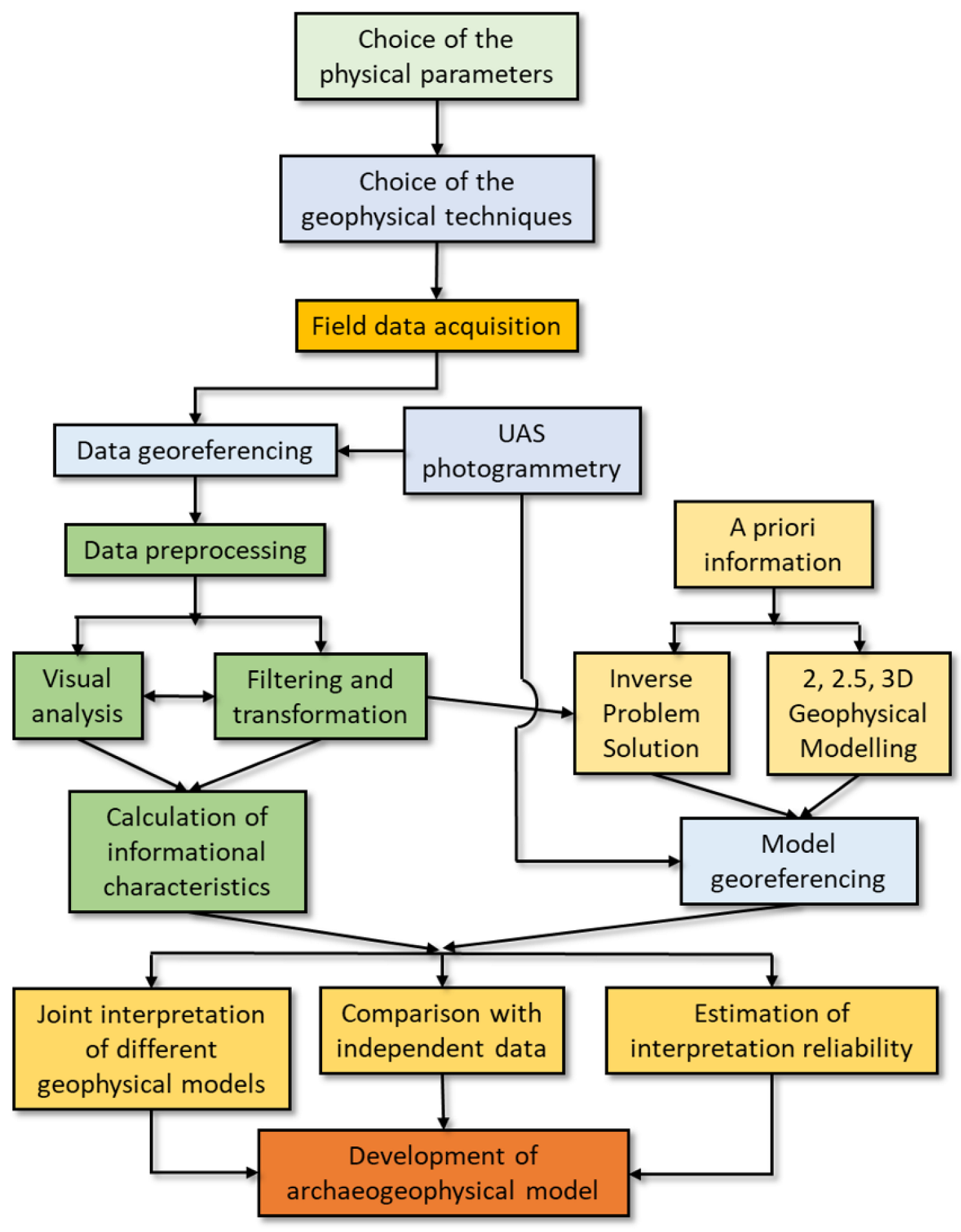
Figure 1. A generalized flowchart of geophysical prospection applied to archaeology.
Heritage 06 00154 g001
Figure 2. Sketch of two typical configurations encountered in an archaeological prospection: a filled hole left after a block removal (left) and a buried prismatic block (right), both covered with uniform topsoil. Vertical gradiometry is performed with two sensors vertically aligned and conveniently spaced. As an example, the graph line shows a typical bipolar anomaly along a E–W trending profile that results from a block (0.25 m × 0.50 m) buried at 0.25 m with susceptibility of 0.05 S.I. and assuming an inclined reference magnetic field (45,000 nT intensity, 45° inclination, 2° declination).
Heritage 06 00154 g002
Figure 3. Comparison between the raw (left) and filtered (right) maps of the total magnetic field (top) and of the vertical gradient (bottom).
Heritage 06 00154 g003
Figure 4. The three directional derivatives: x (top left), y (top right), and z (bottom left), along with the 3D resultant amplitude of the analytical signal (bottom right).
Heritage 06 00154 g004
Figure 5. 2D inversion performed on the example section shown in Figure 3. Top: comparison between the observed total magnetic field (blue line) and the calculated field with the compact inversion (red line). Bottom: interpretative model with resolution of 1 m × 0.5 m.
Heritage 06 00154 g005
Figure 6. Schematics of different GPR acquisition techniques.
Heritage 06 00154 g006
Figure 7. Comparison of different profile spacing time slices acquired with a 400 MHz antenna (test site: Chiesa dei 40 Martiri Pisani, Palermo, Italy).
Heritage 06 00154 g007
Figure 8. Comparison between different profile spacing timeslices acquired with a 100 MHz antenna (test site: Chiesa dei 40 Martiri Pisani, Palermo, Italy).
Heritage 06 00154 g008
Figure 9. Comparison between different acquisition grids of profiles acquired with a 400 MHz antenna and a profile spacing of 25 cm (test site: Chiesa dei 40 Martiri Pisani, Palermo, Italy).
Heritage 06 00154 g009
Figure 10. Comparison between different acquisition grids of profiles acquired with a 100 MHz antenna and a profile spacing of 50 cm (test site: Chiesa dei 40 Martiri Pisani, Palermo, Italy).
Heritage 06 00154 g010
Figure 11. Ex-Oratory of Santo Stefano Protomartire in Palermo, Italy: (a) acquisition grid using 100 MHz antenna and (b) acquisition grid using the 400 MHz antenna.
Heritage 06 00154 g011
Figure 12. 2D GPR profile acquired using the 400 MHz antenna passing over the hypothesized crypt.
Heritage 06 00154 g012
Figure 13. Comparison between two corresponding (0–20 ns) time slices acquired with the 400 MHz antenna (a) and 100 MHz antenna (b).
Heritage 06 00154 g013
Figure 14. Electrode arrays suitable for multi-channel acquisition.
Heritage 06 00154 g014
Figure 15. Example of acquisition and inversion in 2D electrical resistivity tomography: (a) distribution of apparent resistivity measures for 2D ERT acquisition using 48 electrodes, 2 m spacing, and a dipole–dipole array; (b) ERT imaging with topographic correction.
Heritage 06 00154 g015
Figure 16. Maximum yield grid, showing the map of potential data for the current dipole AB (indicated by the red points); the blue points indicate the potential electrodes, while the vectors represent the intensity and direction of the electric field considered to choose the potential dipoles needed to obtain the set of apparent resistivity values for the inversion process.
Heritage 06 00154 g016
Figure 17. (a) The Zisa Palace (Palermo, XII century A.D.). (b) The mosaic in the fountain room; the blue points indicate the potential electrodes, while the red points indicate the current electrodes. (c) Injection of water and conductive gel into small perforations, into which small nails were then inserted to inject the current. (d) Examples of current and potential electrodes.
Heritage 06 00154 g017
Figure 18. 3D-ERT imaging of the mosaic wall of the “Fountain Room” in Zisa Palace (Palermo, NW Sicily). The depth of investigation is about half the thickness of the wall. The isosurface highlights the main funnel-shaped conductive anomaly.
Heritage 06 00154 g018
Figure 19. Representation of aerial photo parameters in a series of shots for a single flight line; here, f = focal length, H = flying height, and S = sensor height/width.
Heritage 06 00154 g019
Figure 20. (A) Dense point cloud of the Selinunte experimental plot (Sicily, Italy), with blue squares representing the estimated camera positions. (B) Aerial triangulation processing.
Heritage 06 00154 g020
Figure 21. (A) Dense point cloud model and (B) Digital Surface Model (DSM) derived from aerial photographic mapping of the northern acropolis fortifications at Selinunte, SW Sicily.
Heritage 06 00154 g021
Figure 22. (A) Aerial survey location map and the ancient planimetry pattern in the north-western termination of the Kamarina archaeological site; (B) high-resolution orthomosaic map; (C) aerial thermographic map, with the dotted line marking the thermal anomaly.
Heritage 06 00154 g022
Figure 23. Location of the archaeological study area, focusing on the ancient housing complex.
Heritage 06 00154 g023
Figure 24. UAS survey and mapping: (AC) flight planning and settings and (D) resulting aerial magnetic map; the dotted circles indicate the informational panels.
Heritage 06 00154 g024
Figure 25. Comparison of the technical characteristics (resolution, coverage, and depth) and of the required survey effort (time and cost) between the various techniques described in this review.
Heritage 06 00154 g025
Table 1. Comparison between the characteristics of three main types of magnetometers.
FluxgateProton PrecessionCesium Vapor
Sensitivityfrom 1 nT to 0.1 nTfrom 0.1 nT to 0.01 nT<0.01 nT
ProsRugged and lightweightFree orientation, rugged, simple, no heading errorGreat versatility and high precision
ConsMust be orientedMore precise models are bulky, heavy, and have high power consumptionFragile, heading errors
ApplicationsVersatile; mainly airborne and gradiometryMarine, airborne, and ground surveyGround survey, airborne, gradiometry, labs, etc.
Suitability for archaeology/cultural heritagePreferable for UAS-based surveysPreferable for ground-based surveysSuitable but not recommended
Disclaimer/Publisher’s Note: The statements, opinions and data contained in all publications are solely those of the individual author(s) and contributor(s) and not of MDPI and/or the editor(s). MDPI and/or the editor(s) disclaim responsibility for any injury to people or property resulting from any ideas, methods, instructions or products referred to in the content.