Article

Understanding the Char-Bending Technique in Shipwreck Planks

Department of Maritime Civilizations, The Leon Recanati Institute for Maritime Studies, University of Haifa, Haifa 3498838, Israel
*
Author to whom correspondence should be addressed.
Heritage 2023, 6(2), 1754-1767; https://doi.org/10.3390/heritage6020093
Submission received: 17 December 2022 / Revised: 1 February 2023 / Accepted: 2 February 2023 / Published: 6 February 2023
(This article belongs to the Special Issue Shipwreck Archaeology)

Abstract

:
Char-bending is a term used in marine archaeology literature to describe the process of shaping long hull components (planks, wales, stringers) by bending them over open fire, from Antiquity, up to modern times. Experiments were done on planks of two wood species with different cross-sections. The planks were heated over open fire while monitoring the internal temperature and charred layer thickness on the side of the plank facing the heat source. The results show that in order to reach the temperature inside the wood required for it to become pliable, the formation of a charred layer, an undesirable by-product, is unavoidable. It is explained why char-bending, in almost all cases, occurs on the concave side of the plank.

1. Introduction

Wood-bending techniques have been known and practiced for at least 4600 years in the production of components of ships, furniture, casks, chariots, and various tools [1]. The idea behind bending wood components to a specific curve is based on several arguments: to keep the grain aligned with the shape of the timber to maintain its strength as much as possible, to reduce the force needed to bend the wood, to prevent fracture of the wood when the curvature of the bend is too sharp, and to prevent spring-back of the timber after bending. Thermo-hydro-mechanical (THM) treatment for preparing a timber, such as a plank, for bending involves heating it in the presence of water for the time needed to allow the heat and moisture to penetrate throughout to make it pliable enough to achieve the correct shape. This process is still used in industry in the production of boats, furniture, and casks [1].
Among the methods of preparing wood for bending are: heating over open fire, steaming, soaking in water, and boiling in water. This work concentrates on heating over open fire. A feature of this process is charring of the face exposed to heat. Aspects of this method that were checked are: whether the charring is on the convex or concave side of the plank; the temperature gradient within the wood as a function of time, and the thickness of the charred layer as a function of time. Evidence of charred wood found in shipwrecks was examined and analyzed to discount other possible reasons for the charring.

1.1. Ancient Written Evidence

The earliest known written evidence is believed to be a contemporary description of char-bending from the 1st century BCE by Valerius Flaccus [2]. Claesson Rålamb described the process used by Vikings in the 11th century as heating planks over a bonfire while applying a downward bending moment (Figure 1).

1.2. Shipwreck Evidence

Many observations of charring in shipwrecks are related to a bending process. The earliest is from the 4th century BCE—in the Kyrenia shipwreck [4]. Most of the evidence is dated to the medieval era, and was found on the eastern shores of the Mediterranean and in the Yenikapı site, Istanbul (Table 1).

1.3. Modern Evidence (20th–21st Centuries)

Preparing vessel components for bending is practiced nowadays in small shipyards in Japan, Bangladesh, South China, East Africa shores, Greece, and many other places (Figure 2). It was recorded by scholars during the 20th and 21st centuries. Greenhill mentioned using the char-bending technique in fishing boat building in Japan in the 20th century, but gave no details [22]. In Bangladesh, char-bending was practised in building fishing boats [23]. In the same area, char-bending is practiced in the production of dug-out canoes to push out the sides of the boat [24]. Richards describes the process of bending planks over open fire in Western Sarawak, Malaysia, and South China, where heating is done over open fire while applying a bending moment to the plank [25]. A similar process in a small shipbuilding yard in the Swahili Coast, East Africa is described by De Leeuwe [26].

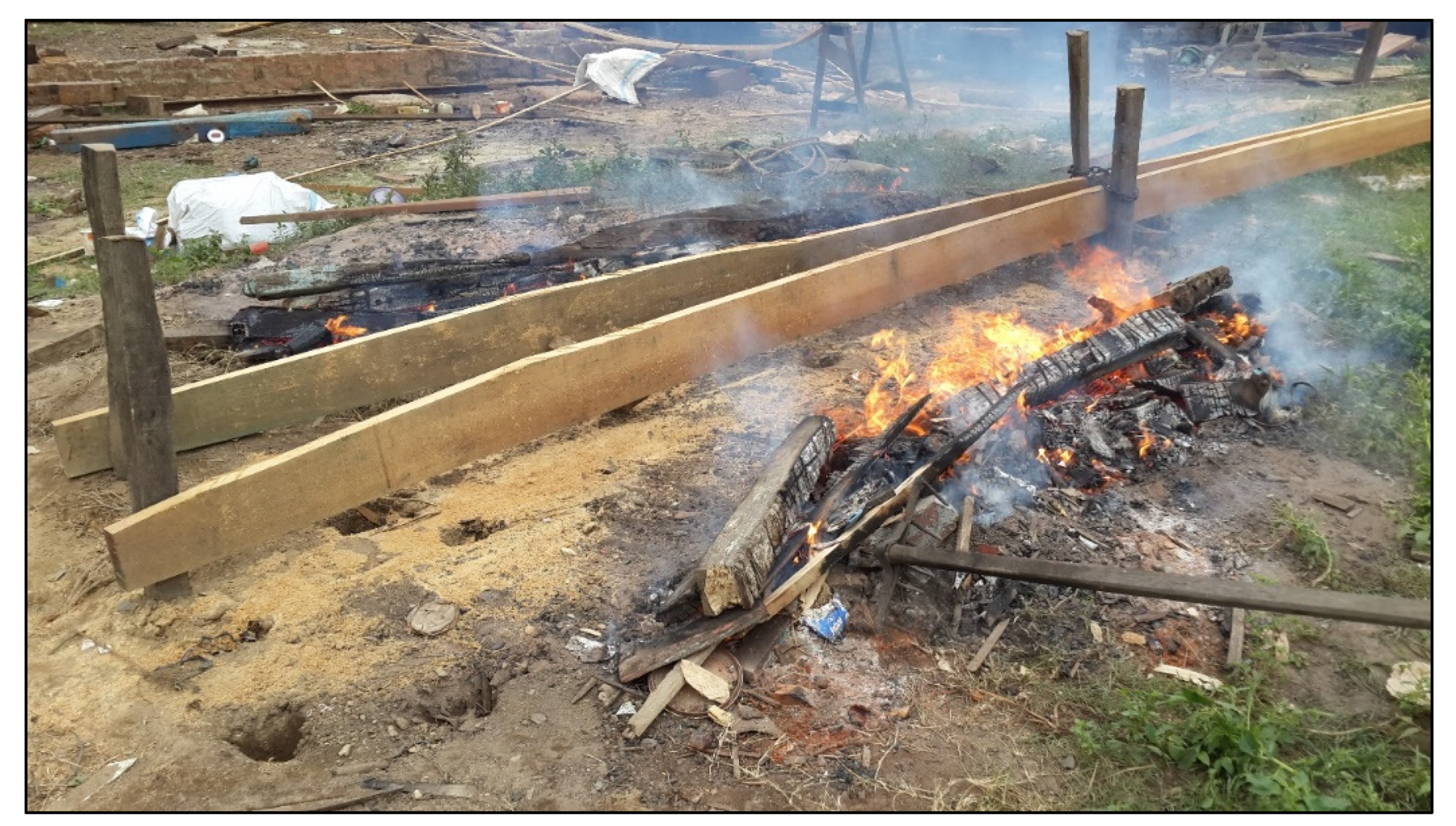
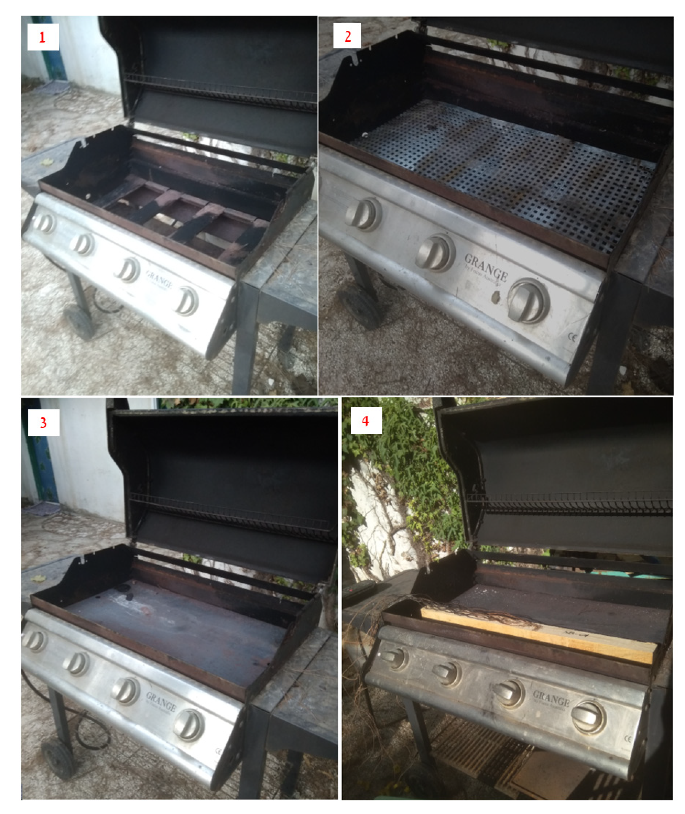
2. Materials and Methods

The THM process of preparing planks for bending is based on the influence of heat and moisture on the wood to make it pliable [1], and for it to be applicable it is required that the temperature and moisture content are uniform throughout the plank.
We know that the mechanical properties of wood change with temperature and with moisture. The temperature should be above a certain value throughout the volume of the plank under consideration. We carried out experiments to better understand the dependency of the temperature inside the wood on the time of exposure to the heat, the wood condition (green, seasoned or wet-seasoned) and the thickness of the charred layer; several series of experiments were carried out.
It may be noted that there is some confusion in the definition of ‘seasoned wood’: in some places it is defined as drying in a kiln at 100 °C [1]; in others it is described as ‘air-dried wood’ [27]. In this work, ‘seasoned wood’ means ‘air-dried wood’, and ‘wet-seasoned wood’ means ‘air-dried wood’ soaked in water until saturated.
The method of heating over open fire in Antiquity was based on a bonfire over which the wood was heated (Figure 1 and Figure 2). Since a bonfire is not a reliable heat source and its distance from the heated object is difficult to control, it was replaced in our experiments by a commercial barbeque device, operated by LPG (liquefied petroleum gas)—a mixture of propane and butane. The timbers were laid on it, and the distance from the heat source and the flame height were kept constant (Figure 3). After several trial experiments, including direct fire (Figure 3(1)), a perforated plate between the flame and the wood (Figure 3(2)), and a solid plate between the flame and the wood, it was decided that the optimal set-up to minimize charring was to lay the wood flat on a 3 mm thick steel plate placed over the flames to spread the heat evenly (Figure 3(4)).

3. Methodology

Two series of experiments were carried out: one on timbers of Turkish pine (Pinus brutia), of 5 × 5 cm cross-section, and the other on cypress (Cupressus sempervirens L.) of 14 × 14 cm cross-section.
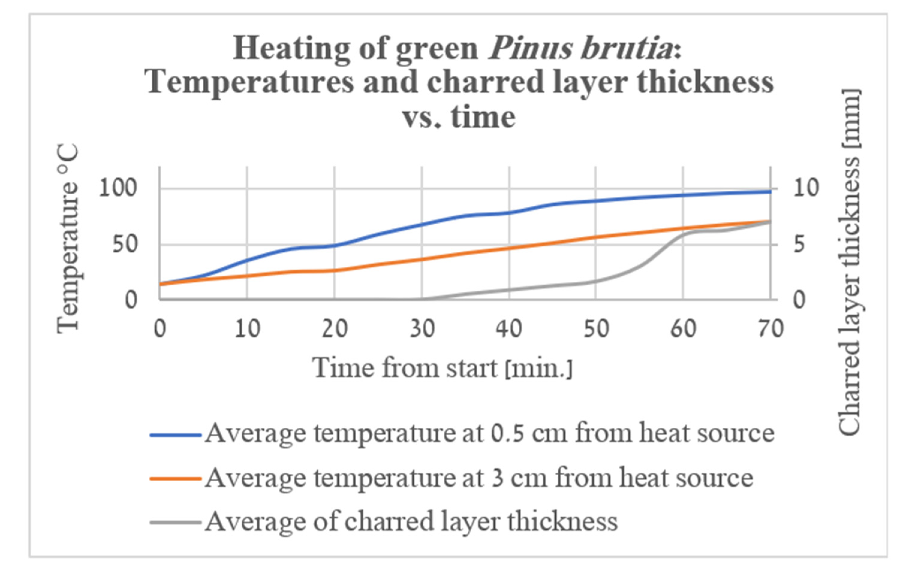
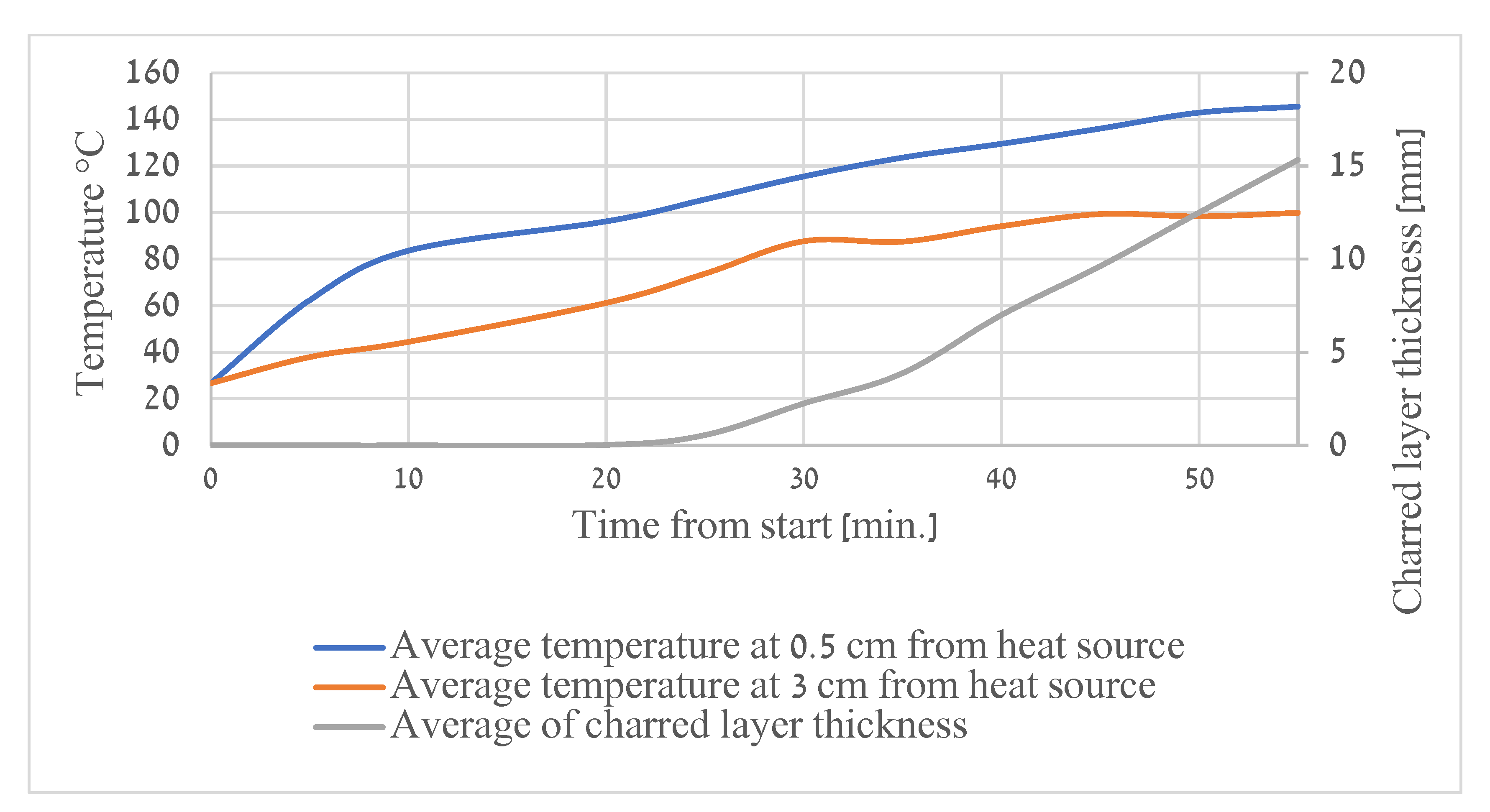
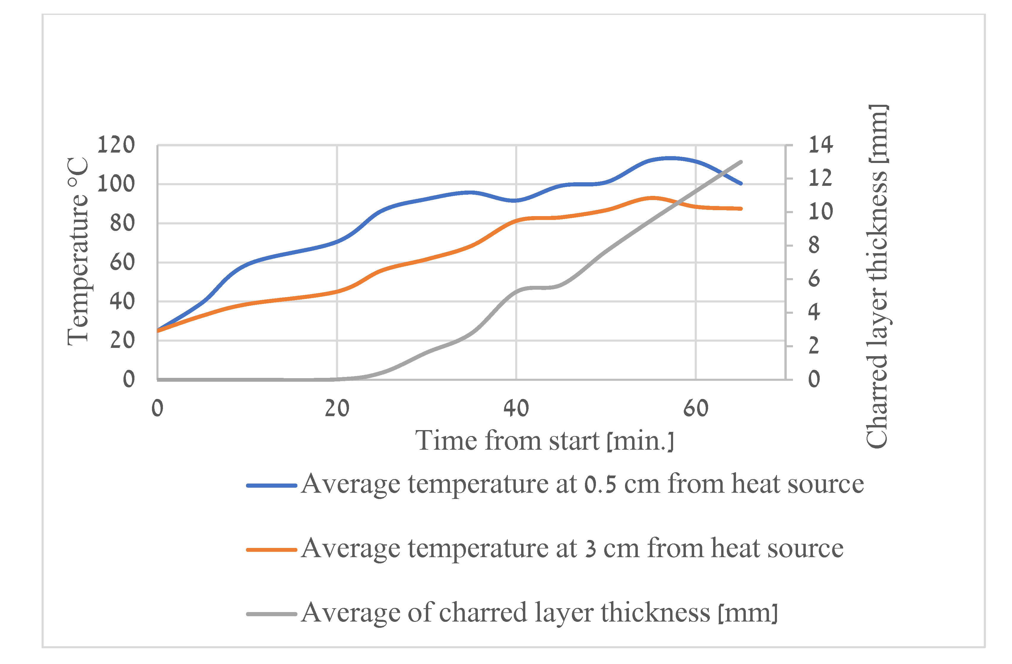
  • Three sets of timbers were cut from P. brutia. The first set was of green wood, the second of seasoned wood, and the third of wet-seasoned wood. The temperature in the wood was measured with thermocouples located inside holes positioned 0.5 and 3 cm from the side facing the heat source.
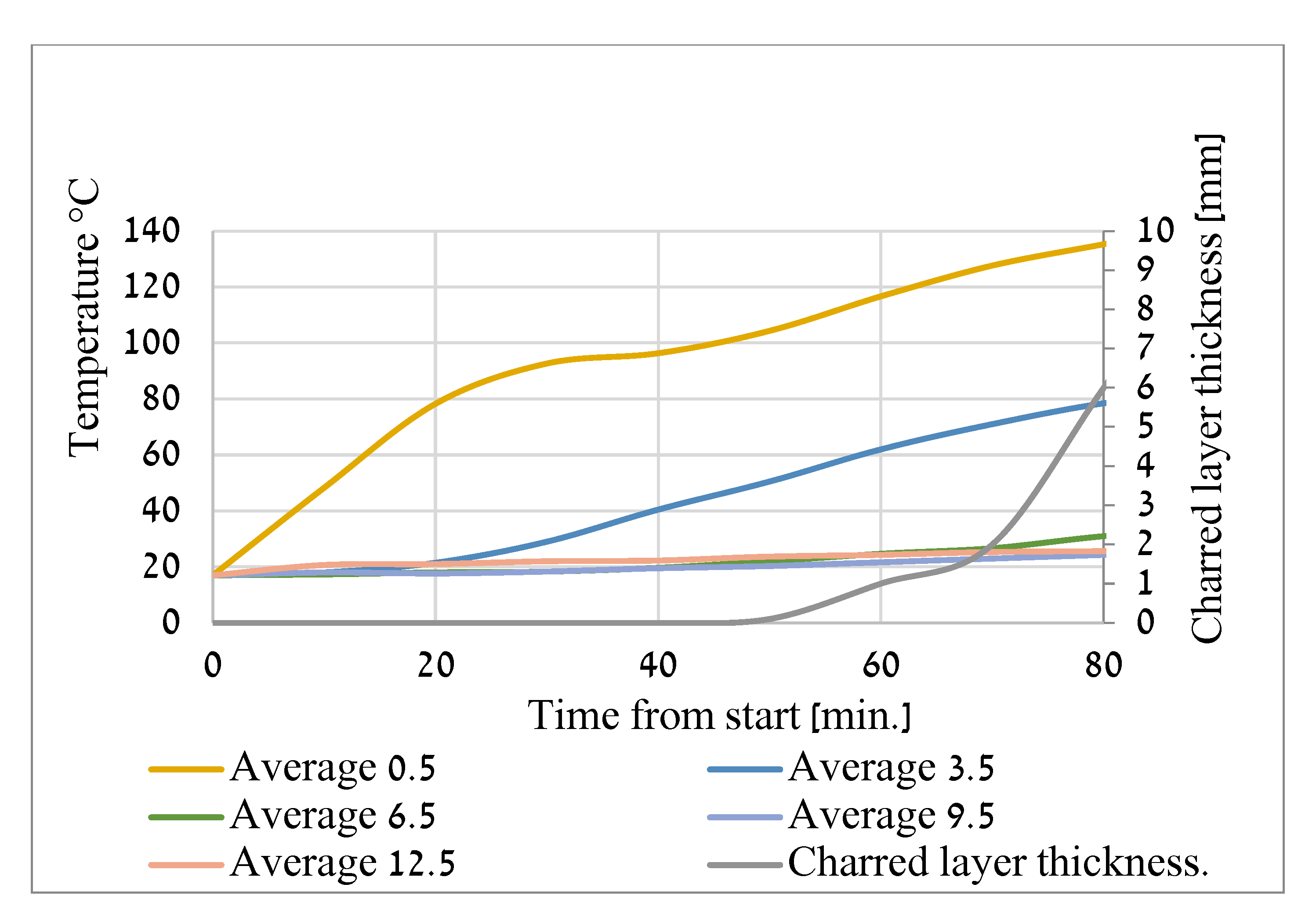
  • Two sets of timbers were cut from a trunk of C. sempervirens. One was seasoned and the other was wet-seasoned. The temperature in the wood was measured with thermocouples located inside holes positioned 0.5, 3.5, 6.5 and 9.5 cm inside the wood on the side facing the heat source.
The thermocouples, Type K, gauge 20, were connected to a model EXRTECH 42150 recorder and the temperatures were recorded every 5 to 10 min.
The thickness of the charred layer created on the side facing the heat source was recorded in parallel as a function of time.

4. Results

Series 1:
In the green P. brutia wood charring began when the average temperature reached 35 °C (Figure 4).
In the seasoned P. brutia wood charring began when the average temperature reached 60 °C (Figure 5).
In the wet-seasoned P. brutia wood charring began when the average temperature reached 45 °C (Figure 6).
Series 2:
In the seasoned C. sempervirens wood charring began when the average temperature reached 40 °C (Figure 7).
In the wet-seasoned C. sempervirens wood charring began when the average temperature reached 23 °C (Figure 8).
In all the experiments it was shown that charring began long before the temperature inside the wood reached the desired temperature, about 100 °C.
Note: The uneven increases in temperature and charred layer thickness in Figure 4, Figure 5, Figure 6, Figure 7 and Figure 8 are due to averaging of the measured data.

The Special and Unique Case (So Far) of the Charred Stringer from the Ma‘agan Mikhael B Wreck

The Ma‘agan Mikhael B (MMB) wreck is a merchant ship about 20 m long, dated to the 7–9th century CE, found off the shore of Kibbutz Ma‘agan Michael, some 35 km south of Haifa in Israel [28]. This ship has about 10 stringers that run along the ship, from stern to bow. One of them, HL-12, had a cross-section of a half log, and was originally 5 m long. It was bent along its length with its flat face of the cross-section facing the convex side of the bent beam and nailed to the frames of the ship (Cohen and Cvikel) [14]. A piece 2 m long was retrieved and examined in the laboratory. The unique feature of this stringer was the charring. In all cases of charred wood found in wrecks (Table 1), as well as evidence recorded in small shipyards in the Levant and the Far East from the 20th and 21st centuries, the charring appears on the concave side of the wood. In this stringer, the charring appears on the convex side (Figure 9).
This blackened area of the stringer was believed to be charring, but was also suspected to be a fungus culture grown on the wood due to its stay of about 14 centuries under water. Six samples were prepared and checked under a scanning electron microscope (Jeol EDS system), and the relative amount of carbon (C), expressed as percentage of the total (Atom count) elements in the sample. This procedure was based on the understanding that the relative amount of carbon in charred wood would be higher than that in the same non-charred wood, due to burning and evaporation of other elements by heat. Black samples taken from the wreck were also checked for the existence of fungus.
Samples:
Sample no. 1: Black piece 1 cm thick.
Sample no. 2: Black piece 0.1 cm thick.
Sample no. 3: Non-black piece 0.1 cm thick.
Sample no. 4: Charred piece 1 cm thick of C. sempervirens—positive control group.
Sample no. 5: Non-charred piece 0.1 cm thick of C. sempervirens—negative control group.
Sample no. 6: Non-charred piece 1 cm thick of C. sempervirens—negative control group.
The results showed that the concentration of carbon in the black material taken from the MMB wreck was similar to the charred positive control group (Figure 10). There was no evidence of fungus in the samples.
Until now, we have had no knowledge whether the other stringers from the MMB wreck were charred, and if they were, on which face of the cross-section the charring appears. We offer two explanations of the ‘wrong’ location of charring on the HL-12 stringer from MMB wreck: The first is that it was a mistake of the shipwright. The second is based on the heat transfer in a beam with the same half-log cross-section as the HL-12 stringer. A typical cross-section of a half-log shows that the distance of the mass centre from the flat face is less than that from the round face (Figure 11) [29]. Understanding that the heat from the fire had to reach the mass centre of the half-log, the shipwright chose by intuition to locate the fire facing the flat side of the half-log cross-section.

5. Discussion

We are not sure that there was always charring when a timber was heated over open fire, especially in thin planks, where heat can penetrate the wood before it is charred. It might happen that the wood was charred during the heating, but the charred layer was cut away. We argue that the expression ‘char-bending’ is wrong, a more accurate term would be: ‘preparing for bending by heating over open fire’.
A charred layer in a shipwreck can be interpreted in several ways:
  • Char-bending
  • Prevention or extermination of T. navalis infestation
  • Accidental fire in the ship
  • Thickness reduction.
  • Proximity to heat source in the ship—the galley stove.
In this work we examined only the planks, wales or stringers from shipwrecks that have charred layers in the bent areas of the ship (Table 1). The location of the charring, only on the bent area, disproves the explanation of preventing or exterminating shipworm (Teredo navalis), which would be expected to be over the whole length of the plank, especially those immersed in bilge water, or on the outer side of the ship below the waterline. Actually, there is no evidence for charring of the planks on the side facing the water, where T. navalis attacks. The argument of the existence of T. navalis in the bilge water can be refuted by the fact that in most of the cases charring is close to the bow or stern, which are not the lowest parts of the ship, and where no bilge water is expected. These are also the areas in which the planks and stringers require sharper curvature. The argument which refutes the option of fire in the ship is based on the fact that the charring is only on the planks, not on nearby components, such as frames, futtocks, ceiling planks, stanchions, etc. The argument of thickness reduction (as in the technique practised in dug-out canoes) is refuted by the fact that it would have left no traces of charring, since the charred layer would be removed in the process. The galley fire should not have left any traces on the ships’ wooden components, since the stove was usually surrounded by bricks.
The relation between the effects of heat and moisture content on the mechanical properties of wood was researched by [1,30], and can be summarized as follows. Three components of the wood were considered: cellulose, hemi-cellulose and lignin, and the dependence of each component on moisture was established [31]. The glass transition temperature (Tg) is defined as the temperature at which the wood components become pliable; i.e., below Tg the material is mostly brittle, and above it the material behaves mostly elasto-plastically. The relation between the Tg and the moisture content of the wood shows that the Tg goes down as the moisture content rises. In the lignin the Tg is a clear-cut point (Figure 12), while in the hemi-cellulose and the cellulose it is within a range of moisture content (Figure 13 and Figure 14).
The result of these dependencies shows that the wood’s mechanical properties, MOE (Modulus of Elasticity) and MOR (Modulus of Rupture), decrease when the moisture content rises, i.e., the wood becomes softer and more elastic. Thus, the practice of preparing wood for bending would rely on having the moisture content as high as possible, which reduces the Tg, and the temperature as high as possible, to keep the wood temperature above the Tg. This principle is applied in steaming, boiling in water, and heating green or wet-seasoned wood over an open fire.
In a letter dated to 1663, the writer says that a quantity of wood, destined for shipbuilding, was actually seasoned (dried-out), since it was cut four years earlier. However, since wood for shipbuilding should be in the ‘green’ condition when heated over open fire for bending, this specific batch of wood was unacceptable [33].
The results of the experiments of heating wood over open fire showed that the side of the wood facing the heat source becomes charred long before the temperature inside the wood reaches the desired range of 80–100 °C, (Figure 4, Figure 5, Figure 6, Figure 7 and Figure 8). Thus, it can be stated that charring is an undesired side effect of heating over open fire. This statement is backed by several sources, such as Richards’ description of the process of bending planks over an open fire in Western Sarawak, Malaysia, where he emphasizes that the heating is done without charring the plank [25].
Desmond, in his description of various methods of preparing planks for bending, says that heating over open fire is good only for ‘small scantling’ timbers [34]. Our interpretation is that he meant that large beams would have been charred in the process.
Valerius Flaccus described the process of preparing wood for bending over open fire as: “being softened into pliancy over a slow flame…” [2] which can be interpreted as avoiding charring in the process of heating. Shipwrights would have preferred to avoid the charred layer, since charred wood loses its mechanical properties, and the wood that takes the load is thinner.

Why Does Charring Occur on the Concave Side of Planks, Wales, or Stringers?

In almost all cases of charred wood in shipwrecks which are related to bending, the charring is on the concave side of the wood. The following are possible explanations for this observation:
(a)
Reducing the water content on this side, to prevent possible cracking during bending, due to excess water pressure [31].
(b)
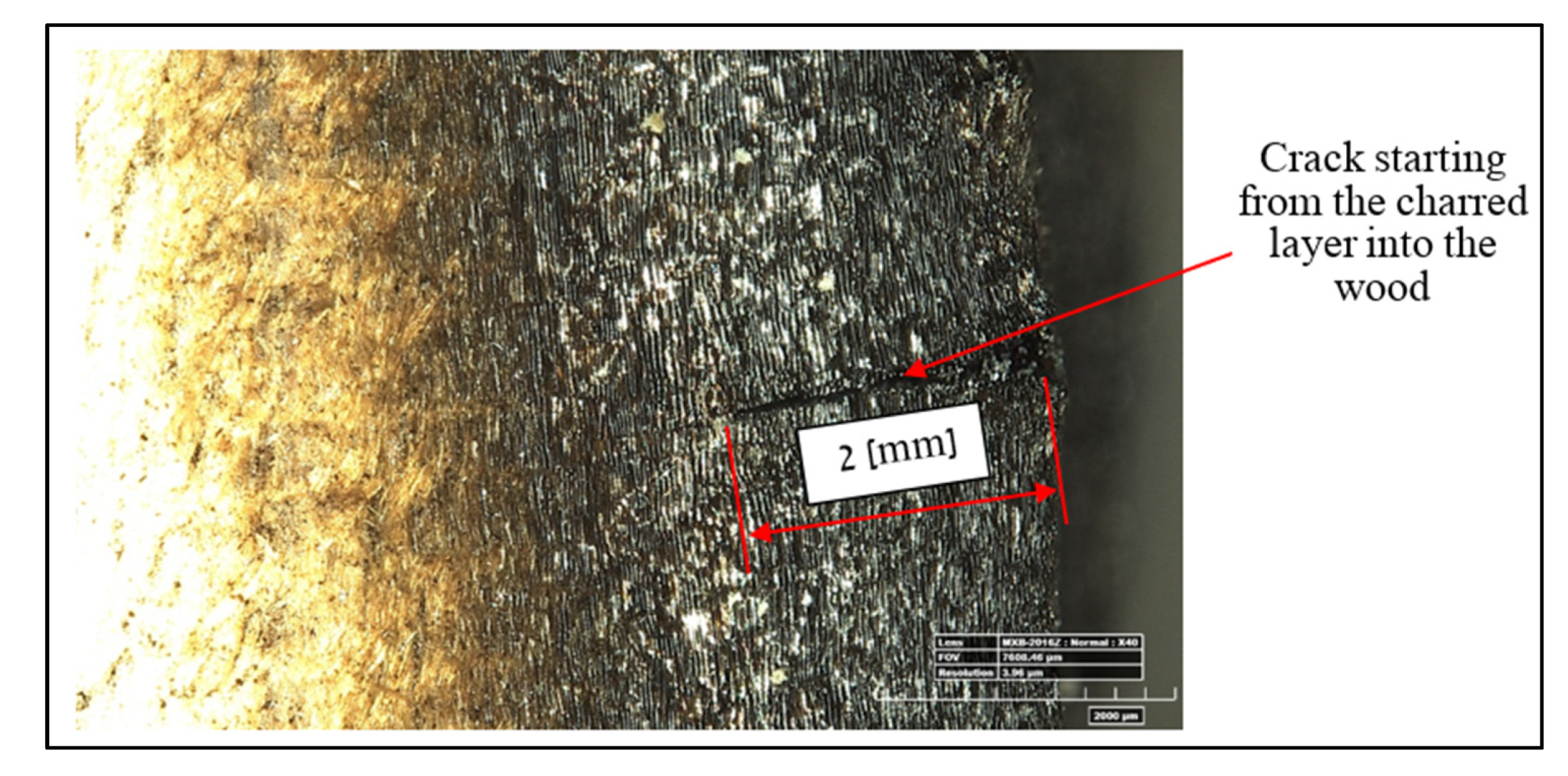
Charred layer on wood is cracked (Figure 15) and cannot carry any load. If the cracked area is subjected to tension, as on the convex side of a bent beam, such cracks could be sites of stress concentration, causing a crack that might extend into the wood under the charred layer
(c)
The heat source evaporates the water on the side it faces, causing the plank to bend.

6. Conclusions

a.
Of all the various methods for preparation of wooden planks for bending, the one involving soaking in water and heating over open fire was probably the most widely used by shipwrights. Wherever such a preparation was deemed necessary for ship building, the charring of the planks was an unwanted side effect only, because it almost always leads to a reduced thickness and thus reduced strength and also to the cracking of the planks and thus to damaging the ship. Ideally, the shipwrights would have preferred to avoid it altogether, although in some cases, such as bending relatively thick planks, charring is unavoidable. To prevent that from happening, another preparation method would have to be used.
b.
When heating a plank over an open fire the side facing the heat source usually contracts (due to evaporation). Therefore, as a preparation for bending, it was almost always done by exposing to the fire the side that at the end of the process would be the concave face of the plank (generally—the inner side of the hull).

Author Contributions

Conceptualization, methodology, software, validation, formal analysis, investigation, resources, data curation, writing—original draft preparation, writing—review and editing, visualization, supervision, project administration and funding acquisition, M.B. and Y.M.-B. All authors have read and agreed to the published version of the manuscript.

Funding

This research was funded by Research Authority of the University of Haifa for a Dov Shafir Fellowship and a Sir Maurice Hatter Fellowship.

Data Availability Statement

Data available on request due to restrictions e.g., privacy or ethical. The data presented in this study are available on request from the corresponding author.

Acknowledgments

To E. Türkmenoğlu and M. Cohen for their generous help.

Conflicts of Interest

The authors declare no conflict of interest.

References

  1. Navi, P.; Sandberg, D. Thermo-Hydro-Mechanical Processing of Wood; Taylor & Francis Group: Boca Raton, FL, USA, 2011. [Google Scholar]
  2. Flaccus, G.V. Argonautica; Loeb Classical Library, Harvard University Press: Cambridge, MA, USA, 1963. [Google Scholar]
  3. Claesson Rålamb, Å. Skepsbyggerij eller adlig öfning tionde tom (Shipwrightry or Noble Practice); Stockholm, Sweden, 1691. [Google Scholar]
  4. Steffy, J.R. The Kyrenia Ship-An Interim Report on its Hull Construction. Am. J. Archaeol. 1985, 89, 71–101. [Google Scholar] [CrossRef]
  5. Van de Moortel, A. Medieval boats and ships of Germany, the Low Countries, and northeast France-Archaeological evidence for shipbuilding traditions. In Shipbuilding Resources, Trade, and Communication, Proceedings of the Rivers as Communication and Trade Routes, Bremerhaven, Germany, 5–7 November 2009; Leidorf: Rahden/Westf, Germany, 2011. [Google Scholar]
  6. Beltrame, C. Preliminary Analysis of the Hull of the Roman Ship from Grado, Gorizia, Italy. Int. J. Naut. Archaeol. 2006, 36, 138–147. [Google Scholar] [CrossRef]
  7. Santamaria, C. L’épave Dramont “E” à Saint-Raphaël (Ve siècle ap. J.-C.). Archaeonautica 1995, 13, 5–198. [Google Scholar] [CrossRef]
  8. Kingsley, S.A. A Sixth-Century AD Shipwreck Off the CARMEL Coast, Israel: Dor D and Holy Land Wine Trade; BAR Publishing: Oxford, UK, 2002. [Google Scholar]
  9. Kahanov, Y.; Mor, H. The Dor 2001/1 Byzantine Shipwreck, Israel: Final report. Int. J. Naut. Archaeol. 2014, 43, 41–65. [Google Scholar] [CrossRef]
  10. Navri, R.; Kahanov, Y.; Cvikel, D. The Byzantine period Dor 2006 shipwreck, Israel: Preliminary hull construction report. Int. J. Naut. Archaeol. 2013, 42, 305–325. [Google Scholar] [CrossRef]
  11. Kahanov, Y. A Byzantine shipwreck (‘Tantura A’) in Tantura lagoon, Israel, its hull construction. In Tropis VI, Proceedings of the 6th International Symposium on Ship Construction in Antiquity Lamia, 28–30 August 1996; Tzalas, H., Ed.; Hellenic Institute for the Preservation of Nautical Tradition: Athens, Italy, 2001; pp. 265–271. [Google Scholar]
  12. Israeli, E.; Kahanov, Y. The 7th–9th Century Tantura E Shipwreck, Israel: Construction and reconstruction. Int. J. Naut. Archaeol. 2014, 43, 369–388. [Google Scholar] [CrossRef]
  13. Barkai, O.; Kahanov, Y. The Tantura F shipwreck: Hull remains and finds-final report. Int. J. Naut. Archaeol. 2016, 45, 6–28. [Google Scholar] [CrossRef]
  14. Cohen, M.; Cvikel, D. Ma-agan Mikhael B, Israel: A preliminary report of a Late Byzantine–Early Islamic period shipwreck. Int. J. Naut. Archaeol. 2019, 48, 189–207. [Google Scholar]
  15. Ingram, R. The Hull of Yenikapı Shipwreck YK 11: A 7th-century merchant vessel from Constantinople’s Theodosian Harbour. Int. J. Naut. Archaeol. 2018, 47, 103–139. [Google Scholar] [CrossRef]
  16. Jones, M.R. The Hull Construction of Yenikapı 14 (YK 14), A Middle Byzantine Shipwreck from Constantinople’s Theodosian Harbour, Istanbul, Turkey. Int. J. Naut. Archaeol. 2017, 46, 253–283. [Google Scholar] [CrossRef]
  17. Türkmenoğlu, E. Preliminary Report on the Yenikapı 17 Shipwreck. In Between Continents: Proceedings of the Twelfth Symposium on Boat and Ship Archaeology, Istanbul 2009; Gunsenin, N., Ed.; Ege Yayinlari: Istanbul, Turkiye, 2009; pp. 121–125. [Google Scholar]
  18. Kocabaş, U. Yenikapı Shipwrecks. In The ‘Old Ships’ of the ‘New Gate’; Ege Yayinlari: Istanbul, Turkiye, 2008; Volume I. [Google Scholar]
  19. Schweitzer, H. Drogheda boat: A story to tell. In Between Continents: Proceedings of the Twelfth Symposium on Boat and Ship Archaeology, Istanbul 2009; Günsenin, N., Ed.; Ege Yayinlari: Istanbul, Turkiye, 2009; pp. 225–231. [Google Scholar]
  20. Lemée, C.P.P. The Renaissance Shipwrecks from Christianshavn; Viking Ship Museum, National Museum of Denmark: Copenhagen, Denmark, 2006. [Google Scholar]
  21. Cvikel, D.; Kahanov, Y. The 19th-Century Akko 1 Shipwreck, Israel: Hull-construction report. Int. J. Naut. Archaeol. 2013, 42, 167–187. [Google Scholar] [CrossRef]
  22. Greenhill, B. Japanese inshore fishing boats. Mar. Mirror 1959, 45, 3–13. [Google Scholar] [CrossRef]
  23. Greenhill, B.; Hill, C. The boats of East Pakistan a preliminary study-1. Mar. Mirror 1957, 43, 106–134. [Google Scholar] [CrossRef]
  24. Greenhill, B.; Hill, C. The boats of East Pakistan a preliminary study-2. Mar. Mirror 1957, 43, 203–215. [Google Scholar] [CrossRef]
  25. Richards, A. Sailing boats of western Sarawak. Mar. Mirror 1967, 53, 161–169. [Google Scholar] [CrossRef]
  26. De Leeuwe, R. Seascape and Sailing Ships of the Swahili Shores. Master’s Thesis, University of Leiden, Leiden, The Netherlands, 2004. [Google Scholar]
  27. Steffy, J.R. Wooden Shipbuilding and the Interpretation of Shipwrecks; Texas A&M University Press: College Station, TX, USA, 1994. [Google Scholar]
  28. Cohen, M.; Cvikel, D. Rigging of the Ma‘agan Mikhael B shipwreck (7th–8th centuries AD): New finds. Int. J. Naut. Archaeol. 2020, 49, 291–302. [Google Scholar] [CrossRef]
  29. Young, W.C.; Budynas, R.G. Roark’s Formulas for Stress and Strain, 7th ed.; McGraw-Hill: New York, NY, USA, 2002. [Google Scholar]
  30. Shi, J.L.; Kocaefe, D.; Zhang, J. Mechanical behavior of Quebec wood species heat-treated using thermowood process. Holz Als Roh-Und Werkst. 2007, 65, 255–259. [Google Scholar] [CrossRef]
  31. Forest Products Laboratory. Wood Handbook-Wood as an Engineering Material; General Technical Report FPL-GTR-190; USDA Forest Service Madison: Wisconsin, WI, USA, 1999. [Google Scholar]
  32. Back, E.L.; Salmén, L. Glass transitions of wood components hold implications for molding and pulping process. J. Tech. Assoc. Pulp Pap. Ind. 1982, 65, 107–110. [Google Scholar]
  33. Staatsarchiv des Kantons Bern. B II 632. Council of War of Berne, Governor of Nyon. 28 December 1663; 213–214. [Google Scholar]
  34. Desmond, C. Wooden Shipbuilding; The Rudder Publishing Company: New York, NY, USA, 1919. [Google Scholar]
Figure 1. Heating of ships’ planks over open fire by Vikings, ca 1600 [3].
Heritage 06 00093 g001
Figure 2. Heating of planks over open fire in small boatyard in Vietnam (Photo: M. Yarkowich).
Heritage 06 00093 g002
Figure 3. Commercial grill system used for heating the planks. (1) Burners are exposed. (2) Perforated sheet metal covers the flames. (3) Solid 3 mm sheet metal covers the flames. (4) Wooden plank is laid on the solid sheet metal (photo: M. Bram).
Heritage 06 00093 g003
Figure 4. Heating of green P. brutia; temperature rise and thickness of charred layer as functions of time. The experiment was stopped due to ignition of the wood.
Heritage 06 00093 g004
Figure 5. Heating of seasoned P. brutia; temperature rise and thickness of charred layer as functions of time.
Heritage 06 00093 g005
Figure 6. Heating of wet-seasoned P. brutia (fully saturated); temperature rise and thickness of charred layer as functions of time.
Heritage 06 00093 g006
Figure 7. Heating of seasoned C. sempervirens; temperature rise and thickness of charred layer as functions of time.
Heritage 06 00093 g007
Figure 8. Heating of wet-seasoned C. sempervirens; temperature rise and thickness of charred layer as functions of time.
Heritage 06 00093 g008
Figure 9. Sketch of stringer HL-12 indicating the location of the charring on the flat side.
Heritage 06 00093 g009
Figure 10. Carbon concentration in samples from the MMB stringer and reference groups, showing thickness of the samples.
Heritage 06 00093 g010
Figure 11. Distances of the concave and convex faces of a half-log to the neutral line [29].
Heritage 06 00093 g011
Figure 12. Tg as function of moisture content and temperature in lignin [32] (authors).
Heritage 06 00093 g012
Figure 13. Tg as function of moisture content and temperature in hemi-cellulose [32] (authors).
Heritage 06 00093 g013
Figure 14. Tg as function of moisture content and temperature in cellulose [32] (authors).
Heritage 06 00093 g014
Figure 15. Charred P. brutia with crack (Photo: M. Cohen).
Heritage 06 00093 g015
Table 1. Charred planks interpreted as evidence for preparing for bending over open fire.
ShipwreckDateComponentSide CharredLocation on
Component
Component
Thickness [cm]
InterpretationReference
Kyrenia4th c. BCEWalesConcave inner faceFew 30-cm-long sections. All other places trimmed off6.1, 8Char-bending[4]
Expanded log boat1st c. BCEConcave inner face[5]
Grado2nd c. CEGarboardConcave inner faceExtremities5Char-bending[6]
Dramont E5th c. CEGarboardConcave inner faceExtremities4.8–5Char-bending[7]
Dor D6th c. CEStrakeConcave inner faceExtremities3Char-bending[8]
Dor 2001/16th c. CEStrakeConcave inner faceExtremities2.3Char-bending[9]
Dor 20067th c. CEStrake, waleConcave inner faceExtremities3.2, 16.1Char-bending[10]
Tantura A6th c. CEStrakesConcave inner faceExtremities2.5Char-bending[11]
Tantura E7th–9th c. CEStrakesConcave inner faceExtremities1.9–2.9Char-bending, killing T. navalis[12]
Tantura E7th–9th c. CEStringersConcave inner faceExtremities4–7.6Char-bending, Killing T. navalis[12]
Tantura F7th–8th c. CEStrakesConcave inner faceExtremities2.7Char-bending[13]
MMB7th–8th c. CEStringerConvex outer faceExtremities10Char-bending[14]
MMB7th–8th c. CEStrakesConcave inner faceExtremities3.1–4.2Char-bending[14]
YK 117th c. CEStrakesConcave inner faceExtremities1.8–2.5Char-bending[15]
YK 149th c. CEStrakesConcave inner faceExtremities0.8–3.6Char-bending[16]
YK 149th c. CEGarboardConcave inner faceExtremities1.1–4.4Char-bending[16]
YK 149th c. CEWaleConcave inner faceExtremities3.6–7.2Char-bending[16]
YK 178th c. CEWaleConcave inner faceWhole length14Char-bending[17]
YK 310th–11th c. CEWaleConcave inner face10Char-bending[18]
Drogheda Boat16th c. CEStrakesConcave inner faceAll over2.2Char-bending, killing T. navalis[19]
B&W I16th–17th c. CEStrakesConcave inner faceExtremities4.5Char-bending[20]
Akko 119th c. CEGarboardConcave inner faceExtremities4.5[21]
Disclaimer/Publisher’s Note: The statements, opinions and data contained in all publications are solely those of the individual author(s) and contributor(s) and not of MDPI and/or the editor(s). MDPI and/or the editor(s) disclaim responsibility for any injury to people or property resulting from any ideas, methods, instructions or products referred to in the content.

