1. Introduction
Cultural heritage objects are invaluable physical expressions of human progress and creativity. Scientific examination of these objects affords insight into their constituent materials, which can reveal information about when, where, and how they were created. Of these constituent materials, pigments are of particular interest for many reasons. Pigments are traceable in both time and location and can therefore serve as a temporal and spatial marker of the development and migration of technology [
1]. Additionally, the association of certain pigments with certain periods, artistic styles, and/or specific artists can be useful for authentication and tracking provenance [
2,
3,
4,
5,
6]. Finally, knowledge of the pigments in an object also aids in conservation efforts. Certain pigments degrade via known mechanisms enabling a better understanding of an object’s condition [
7,
8], and pigments used during restoration treatments can be matched to the original pigments once the original pigments are known [
9]. For these reasons, pigment identification is central to the scientific examination of many cultural heritage objects.
There are a number of analytical techniques used to study cultural heritage objects. These techniques can be classified according to their level of invasiveness, ranging from non-invasive, to invasive non-destructive, to invasive destructive. Many of the techniques used most frequently are non-invasive spectroscopies, including UV-Vis [
10], infrared [
11], Raman [
12], and X-ray fluorescence [
13], which enable material characterization without the removal of a sample from an object. These techniques provide complementary information that is combined to infer the chemical identity and structure of a material, and as such, several techniques may be applied over the course of a technical study to develop a comprehensive understanding of an object’s constituent materials. For example, X-ray fluorescence provides elemental information, while infrared provides information about the chemical bonding, which together can be used for molecular identification.
Other analytical techniques require the removal of a sample. Invasive sample-based techniques that do not alter or destroy the sample are considered non-destructive. These are distinct from destructive techniques, from which the sample cannot be recovered in its original state. An example of an invasive non-destructive technique is room temperature electron paramagnetic resonance (EPR) spectroscopy. While it is not as common in heritage science as the previously mentioned spectroscopies, there are some studies in which EPR has been used to study rock paintings [
14], wall paintings [
15], ceramics [
16,
17,
18], marble and limestone [
19,
20], paper [
21], varnishes [
22], and pigments [
23,
24,
25,
26,
27].
Recognizing that the need for sampling may be a factor precluding the adoption of EPR as a common tool used in heritage science, a low frequency EPR (LFEPR) spectrometer that enables non-invasive studies of objects has recently been developed [
28]. Building on this, a subunit of the LFEPR spectrometer called the EPR Mobile Universal Surface Explorer (MOUSE) has been used to demonstrate that LFEPR is an effective portable technique for identifying pigments in artists’ paints [
29,
30,
31,
32,
33].
Using these tools, we have successfully identified the pigment in paint on canvas [
30], mixtures of pigments in paint on canvas [
32], developed an algorithm for identifying pigments [
32,
33], and mapped the spatial distribution of pigments in paint on canvas [
33].
While conventional EPR spectrometers are invasive for all but small samples as they require that the sample be placed within a small resonant cavity, which limits the sample size to its approximately 0.2 cm3 volume, the non-invasive analysis by the EPR MOUSE is carried out by placing the sensor on the sample, thus removing all sample size restrictions. Furthermore, a conventional laboratory EPR spectrometer weighs approximately 900 kg and has significant electrical and cooling requirements. In comparison, the current 65 kg LFEPR spectrometer and 503 g MOUSE, require only wall socket electricity and no water cooling, making it portable.
Recently, spectral databases focusing on visible reflectance, Fourier transform infrared (FTIR), dispersive Raman, X-ray fluorescence, and X-ray diffraction spectra of pigments have been reported in the literature [
34,
35,
36,
37,
38]. These databases are extremely beneficial to the heritage scientist for pigment identification and spectral understanding.
While there are examples of EPR studies of pigments in the literature, many focus on the characterization of a single pigment, and to date, there has been no effort to catalogue in one place the EPR spectra of many diverse pigments. As such, the library of EPR spectral data of artists’ pigments presented here is the first of its kind. At present, the library consists of entries for 51 different pigments that have been studied using both low (400 MHz) and high (9 GHz) frequency EPR spectroscopy, communicating a collection of pigments currently identifiable by EPR performed at different frequencies. It is an open access, living entity that is freely available, and will continue to grow as more pigments are studied at room temperature.
There were several further motivations for creating the library and discussing it herein that are worth noting. The references describing room temperature EPR studies of pigments are challenging to find. First, pigments are often referred to by their chemical name. Older catalogued references often focus on unique theoretical or structural findings while newer ones focus on unique features of the chemical environment in a new crystal matrix, a biological system, or temperatures close to zero Kelvin. Once found, the spectra they contain may not be easily interpretable by nonexperts. As a less common technique in heritage science, EPR in general may be less well understood than techniques that are more frequently used, and that are therefore more familiar. Furthermore, its relative rarity may lead to an alienating association with more advanced scientific analyses requiring expert knowledge and expensive specialized equipment.
Acknowledging these difficulties, the background information presented here to supplement the library aims to explain EPR in an accessible manner, so that the characteristics and features of the spectral data it contains can be approached with understanding. In particular, the differences between conventional EPR and LFEPR spectra are emphasized. This is a point of emphasis, because the comparison highlights the capabilities of the current LFEPR and MOUSE technology and illustrates opportunities for improving portable non-invasive EPR in the future. More broadly, this effort aims to communicate the utility of EPR for pigment identification in heritage science, and to provide an accessible library of reference data to encourage its application in this field.
2. The EPR Signal
This section presents the theory of electron paramagnetic resonance spectroscopy which will assist the reader in understanding the features of the spectra in the library. The reading learner is directed to one of the classic texts for more details [
39,
40], while the kinesthetic learner is directed to the excellent EPR spectral simulation package, EasySpin [
41,
42]. When learning EPR it is helpful to note that the spectra of a single crystal, a powder or amorphous solid sample, and a non-viscous liquid solution will be distinct. This distinctness is a feature that makes EPR valuable as an analytical tool but can be challenging for the novice to learn. For the EPR of a pigment, either neat or set in a paint binder, knowledge of the background for powder or amorphous solid samples and a little insight into crystals will suffice.
There are three general classes of magnetic matter: diamagnetic, paramagnetic, and ferro or ferrimagnetic. The majority of matter is diamagnetic meaning it possesses no magnetism. Paramagnetic substances possess a magnetic moment, typically due to the presence of unpaired electrons, when placed in an external magnetic field. Ferro and ferrimagnetic materials possess an inherent magnetism.
EPR spectroscopy is an analytical technique used to study paramagnetic substances. The filling rules for electrons in atomic and molecular orbitals allow for the possibility of unpaired electrons and hence a net electronic spin. Molecular species with unpaired electrons are referred to as free radicals. An example is the rock lapis lazuli, which is ground to produce the pigment ultramarine (Na7Al6Si6O24S3) and contains a sulfur centered unpaired electron. Another class of matter with unpaired electrons is transition metal complexes. Blue vitriol (CuSO4 · 5H2O) is an example. The presence or absence of unpaired electrons in these complexes depend on the available electrons, ligand field strength, and the coordination geometry.
To understand the EPR spectroscopy of pigments it is necessary to start at a microscopic level. Powdered pigments are typically composed of particles ranging in size from 1 to 50 µm. These particles are generally small irregular shaped crystals of the paramagnetic substance, although agglomerations of the crystals are possible. A 1 µm diameter crystal of a transition metal complex can have more than 10
9 unpaired electrons. Mulling a pigment brakes up the agglomerates and surrounds the individual crystals with the binder. The pigment does not dissolve in the binder; therefore, the microscopic crystalline particles remain intact. Once the paint binder has polymerized on its substrate, the small crystal particles are locked in a specific orientation and position. The binder is typically a diamagnetic liquid such as linseed oil, possessing no EPR signal, although it may undergo photo degradation over centuries to form free radicals. The binder typically does not react with the pigment, although ligand substitution has been observed in specific cases [
43]. Therefore, the binder has no effect on the EPR signal of the pigment.
We use the generic term paramagnetic species to refer to both free radicals and transition metal complexes. Many pigments possess unpaired electrons which give rise to an observable EPR signal; however, while the presence of an unpaired electron is a necessary condition to observe an EPR signal, this alone is not sufficient to guarantee that a signal will be detected.
2.1. Absorption Characteristics of Spin Systems
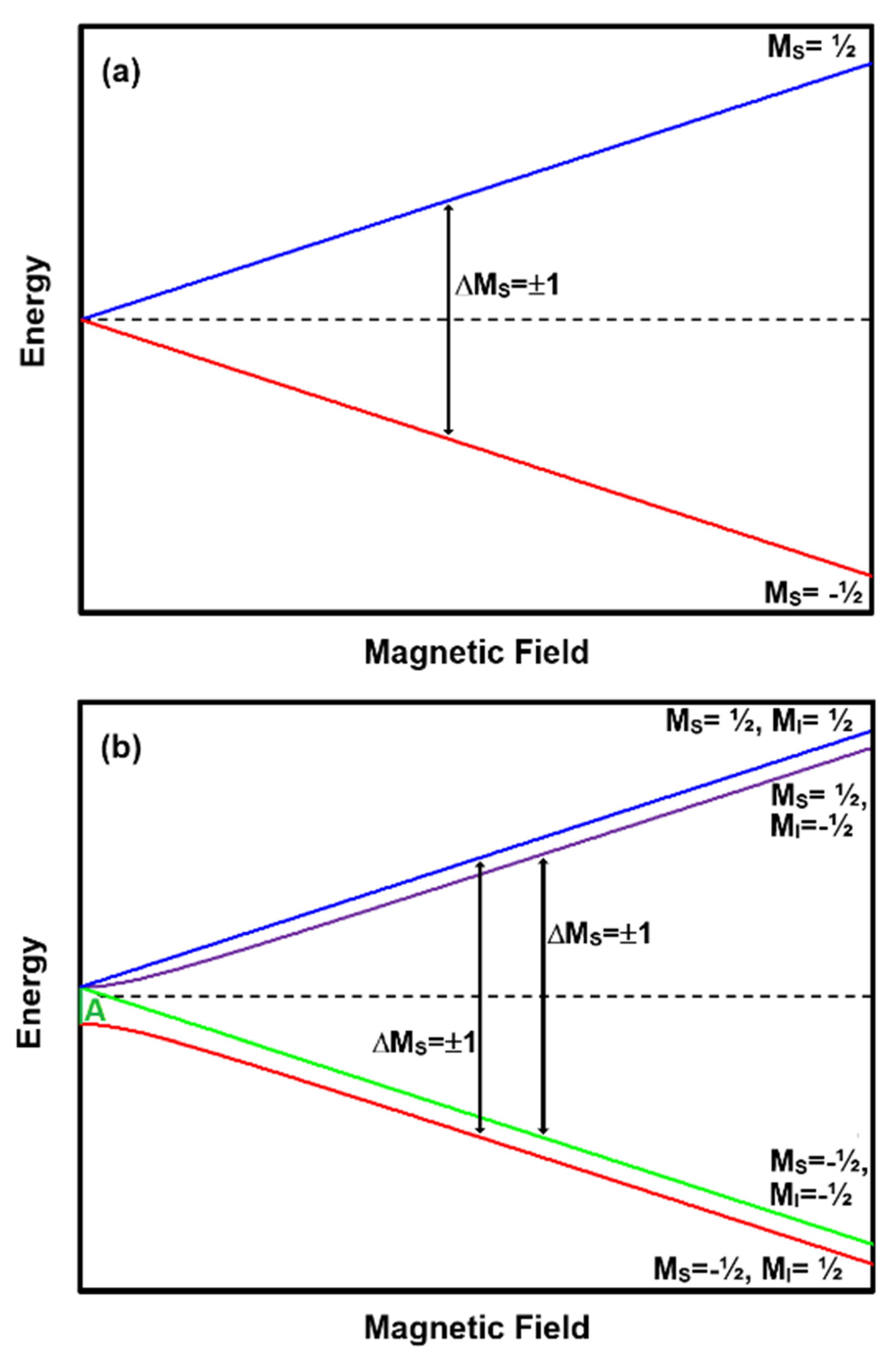
An EPR spectrum is a record of the absorption of electromagnetic radiation at frequency ν by matter with unpaired electrons when placed in an applied magnetic field (B). A single unpaired electron with spin S = ½ can align itself with or opposed to the magnetic field. These two configurations represent the two energy levels or quantum states of an unpaired electron in a magnetic field and are given the symbols M
S = −½ and M
S = ½. Spectroscopists represent the energy of the spin states as a function of B using energy level plots of the spin system (see
Figure 1a). In the lower energy state (M
S = ½) the spins are aligned and in the upper (M
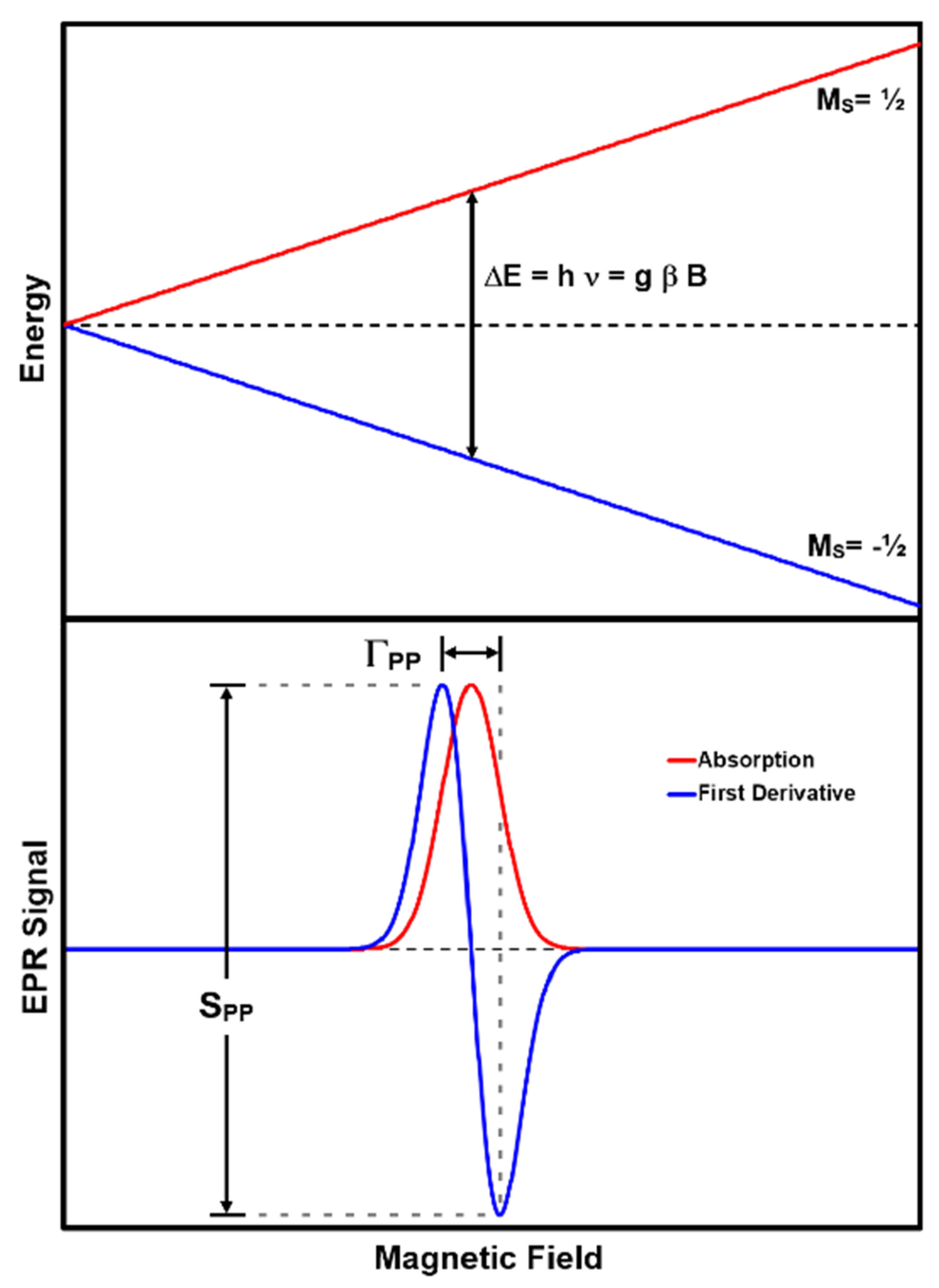
S = −½) opposed to B. The absorption of energy equal to the difference between the two energy levels (ΔE) causes the electron spin to flip from the lower to upper or upper to lower energy levels. The latter absorption of ΔE results in the emission of the original photon and a new one. The relationship between the frequency of the absorbed energy and the magnetic field value at which the absorption occurs is:
where h is Planck’s constant, β the Bohr magneton, and g the electron g-factor [
39]. The g-factor is a unique constant associated with the unpaired electron spin in a specific environment and is therefore a diagnostic feature useful in identifying pigments. EPR transitions between energy levels occur where the M
S of two energy levels differ by ±1 (i.e., ΔM
S = ±1). Note that in this S = ½ system (See
Figure 1a), for any ν there will be a B value that allows a transition between the two states. Therefore, EPR could be performed at any ν value. The pigment charcoal is an example of this spin configuration.
The relationship between ν and B becomes more complex when the atoms have an unpaired nuclear spin (I) or multiple unpaired electrons (S > ½). In these cases, there will be an energy difference between the spin states at the zero applied magnetic field because of the inherent magnetic field associated with the presence of other particles with spin. There is also the possibility that there will be more than two energy levels at a given B value.
Figure 1b presents an energy level diagram for an atom with one unpaired electron experiencing the presence of one unpaired proton. In the case of S = ½ and I = ½, the zero-field energy difference is the hyperfine constant (A) for the atom. We include this spin configuration as a didactic example of an interaction between an electron and a nuclear spin such as in a hydrogen atom. There may be few if any pigments with an S = ½ and I = ½; however, there are numerous pigments with higher spin values. An example seen in numerous library pigments is Mn
2+. The interested reader is directed to the excellent reference by Piligkos et al. for details [
44].
At high ν frequencies there are two distinct EPR absorptions corresponding to ΔM
S = ±1 with ΔM
I = 0 (see
Figure 1b annotations.) As ν gets smaller, the same transitions are not always possible as in the case presented in
Figure 1b because the energy of ν is insufficient to cause a transition between the two spin states. Therefore, the (M
S = −½, M
I = −½) → (M
S = ½, M
I = −½) will always be possible, but the (M
S = −½, M
I = ½) → (M
S = ½, M
I = ½) transition will only be possible when hν ≥ A. Thus, in a system with S = ½ and I = ½, the number of absorptions observed in the EPR spectrum will depend on ν.
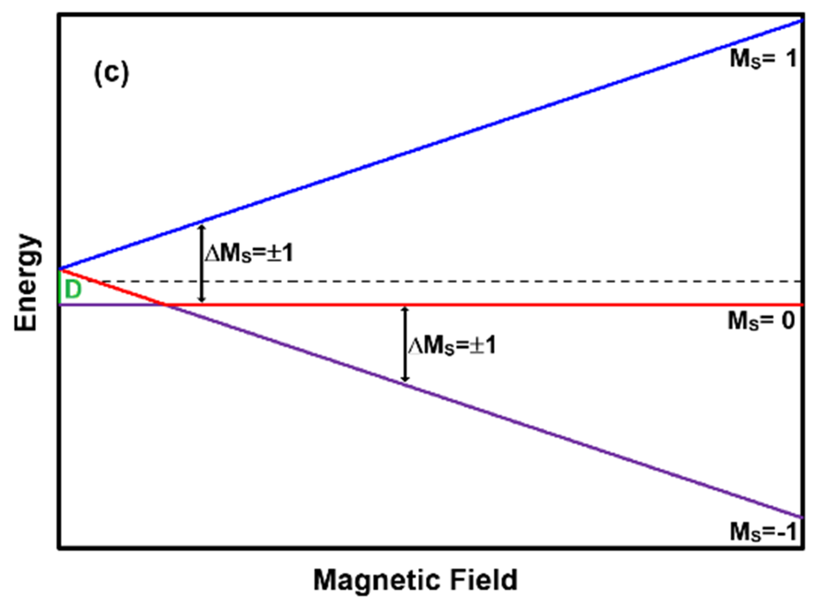
Figure 1c presents the scenario of a two unpaired electron system yielding a zero-field energy difference of D. Transitions between M
S = 0 and M
S = 1 are only possible when hν ≥ D, while the transitions between M
S = 0 and M
S = −1 will always be possible at some B value. For hν < D there will be two transitions between these levels: one to the left of the B value where the M
S = 0 and M
S = −1 levels approach, and one to the right. When hν > D, there will be only one transition between these levels: at some B value to the right of the value where M
S = 0 and M
S = −1 levels approach. Thus, the EPR spectrum of this system always has the possibility of exhibiting two absorptions. An example of an S = 1 spin system is the pigment verdigris, described in detail later. Although I = 3/2, the A value is small and can usually be neglected when examining spectra.
In summary, at any given ν, a spin system with S = ½ will exhibit an absorption at the value of B that satisfies the resonance condition given by Equation (1) and ΔMS = ±1. When considering systems with nuclear spin (I) the inherent hyperfine interaction constant (A) and the possibility for multiple absorptions occurring at different B values must be considered. Similarly, systems with more than one unpaired electron (S > ½) will also possess zero-field energy (D) and give rise to the possibility to observe absorptions at multiple B values.
2.2. Absorption Linewidth
EPR spectra are recorded by sending a fixed frequency into the sample and measuring its absorption while scanning the magnetic field, thus satisfying the resonance condition expressed in Equation (1) [
40]. This approach is referred to as continuous wave (CW) EPR. A spectral absorption occurs when the hν equals the energy difference between two levels in the energy level diagram (ΔM
S = ±1). In practice, spectral absorptions are recorded as first derivatives of their absorption line shape as a function of B (
Figure 2). This is a consequence of employing sinusoidal magnetic field modulation and phase sensitive detection at the modulation frequency to improve the signal-to-noise ratio (SNR) in the spectrum.
Distinct paramagnetic substances will give rise to absorptions with different peak-to-peak amplitudes (S
PP) and widths (Γ
PP). The causes of absorption line broadening that give rise to different Γ
PP are (1) inhomogeneities in the B field over the sample, (2) a short lifetime of the excited spin state causing Heisenberg uncertainty broadening [
40], and (3) anisotropy in the spin parameters such as g, A, and D. Broadening due to inhomogeneities can only be improved by making the B field more spatially homogeneous. Broadening due to Heisenberg uncertainty can only be negated by reducing the sample temperature to close to absolute zero and/or reducing the concentration of the pigment. It is inadvisable to change the temperature of a cultural heritage sample and changing the concentration would render the technique destructive, so this form of broadening is not removable. Lastly, broadening due to anisotropies cannot be removed but should be understood to interpret a spectrum [
45]. Therefore, broadening is largely unavoidable, and while useful as a characteristic, measurable feature of some samples, other samples exhibit broadening so extreme that their absorption is not observable within the sweep widths of current instrumentation.
2.3. Crystal Symmetry and Frequency Dependencies
Due to the spatial geometry of the unpaired electron’s surrounding crystal lattice, it is possible to have isotropic or anisotropic g, A, and D values. A value that is isotropic is the same regardless of the orientation of the paramagnetic species with respect to the direction of the applied magnetic field, while an anisotropic value varies with the orientation of the paramagnetic species with respect to B. An axially symmetric species will have two different g-factors: one when it is aligned with (g
//) and one when it is perpendicular to (g
⊥) B. Paramagnetic species with trimetric crystal geometries will have unique g
x, g
y, and g
z values for the g-factor. With a single crystal sample, it is possible to orient the crystal relative to B so as to see the //, ⊥, X, Y, and Z values of g, A, D, and E; where E is the anisotropic component of D [
45], important only when S ≥ 1. A powder sample, however, is composed of many microscopic crystals. It will therefore have a uniform distribution of all orientations of the small crystals and hence exhibit what is called a powder pattern spectrum. For isotropic samples, there is no difference between a powder and a crystal spectrum, while anisotropic samples will have a difference.
A pigment in a polymerized binder is similar to a powder in that there is a random distribution of the microscopic crystal particles. Unlike optical systems, EPR spectroscopy detects a signal from all spins in each microscopic crystal, not just those on the surface of a crystal or the surface of a painting.
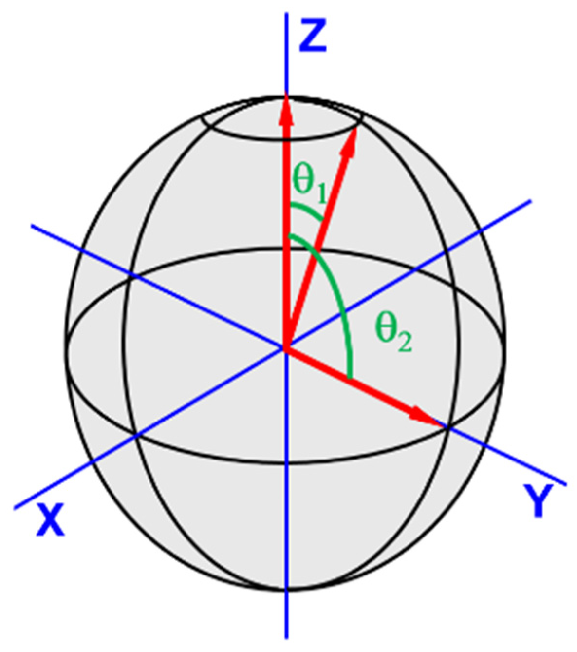
To understand powder pattern spectra, consider an S = ½, I = 0 spin system with an axially isotropic g-factor. Imagine the axis of the paramagnetic species is orientated along the direction of the applied B field, coincidental with +Z (θ = 0) (see
Figure 3). There is just one way the species can take on this orientation. Contrast this with the orientations for the species’ axis that are possible when perpendicular (θ = 90°) to the B field. In this case, there are 360° worth of orientations about Z. There are progressively fewer possible orientations that fit as the angle between the principle axis of the applied field and the paramagnetic species’ axis decreases to zero. Consider next the EPR spectrum for this scenario. There will be a small signal at B corresponding to g
// and a larger signal as B approaches the value for g
⊥.
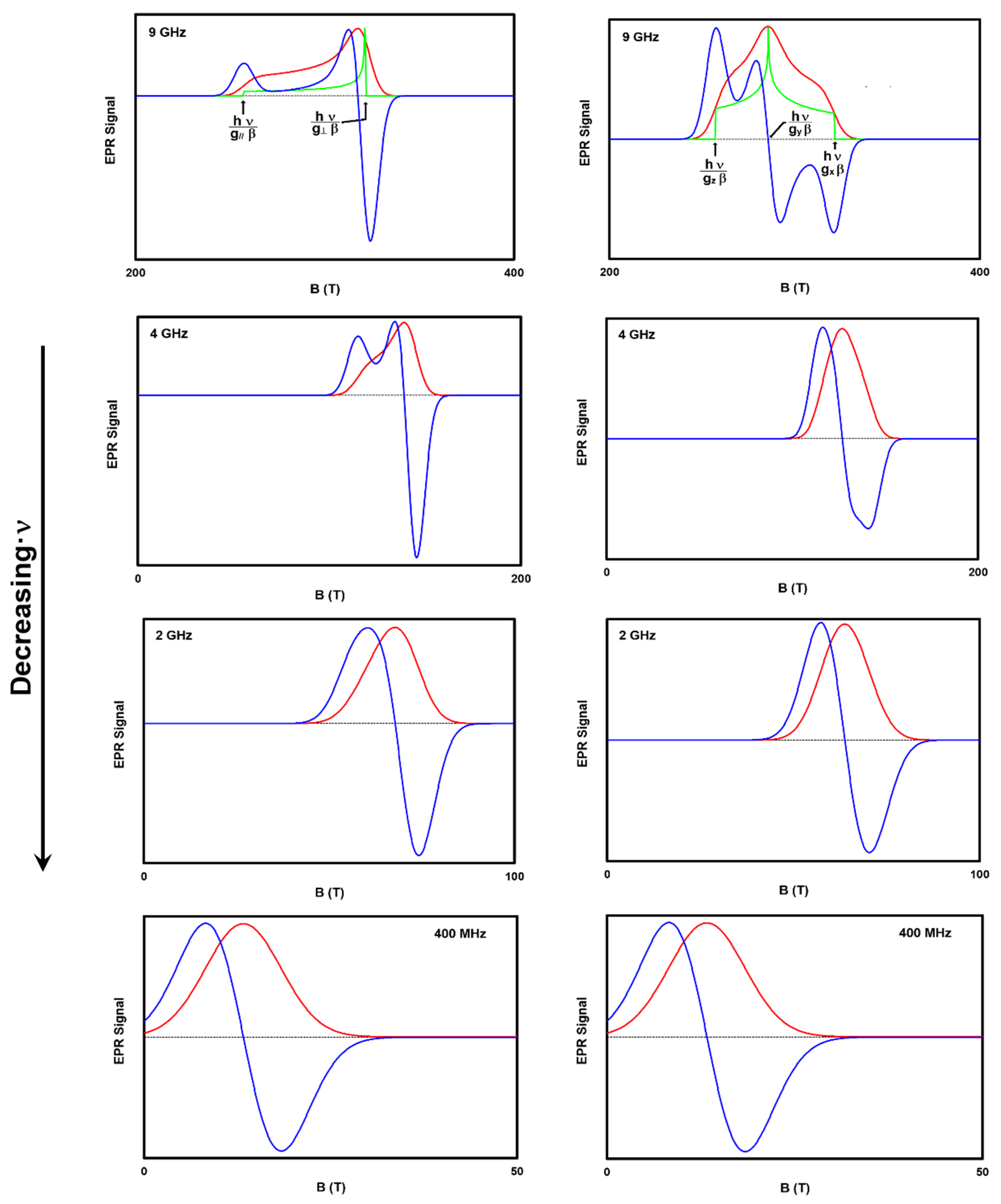
Figure 4 presents spectra simulated with EasySpin for powders with anisotropic g-factors at different B field strengths. A powdered pigment in a paint binder possessing anisotropic EPR properties will have EPR spectra like those presented in this Figure. The first column of spectra is for an axially symmetric g-factor with a large signal at the B corresponding to g
⊥, and a smaller contribution at g
//. This distribution is depicted in the green 9 GHz axial symmetry spectrum. Incorporating line broadening yields the actual absorption spectrum shape (red) corresponding to the first derivative spectrum (blue).
Similarly, the right column of
Figure 4 depicts spectra for a paramagnetic species with trimetric symmetry (g
x ≠ g
y ≠ g
z). The green trace in the 9 GHz spectrum depicts the distribution of orientations, while the red incorporates the absorption linewidth, and the blue the recorded first derivative.
As ν decreases, it becomes more difficult to measure, observe, and calculate distinct g
//, g
⊥, g
x, g
y, and g
z. This is depicted in
Figure 4 by comparing the loss of spectral detail upon going from ν = 9 to 4 to 2 to 0.4 GHz. Additionally, the average g-factor (e.g., ½(g
// + g
⊥)) can deviate from the observed g-factor as the ν decreases. The library entries for Han blue and Egyptian blue demonstrate this. These inconsistencies are some of the justifications for a spectral library including measurements from both high and low frequencies.
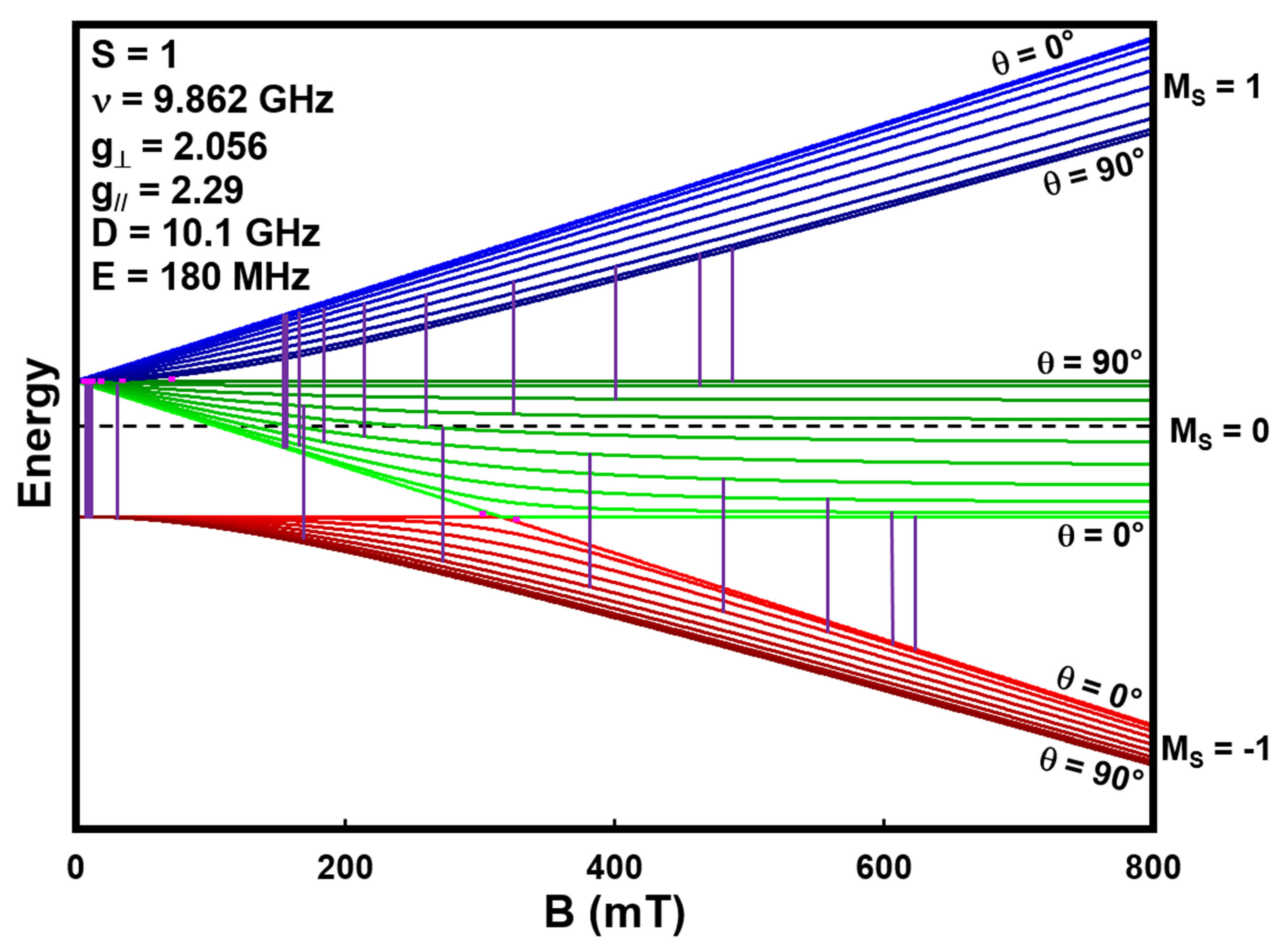
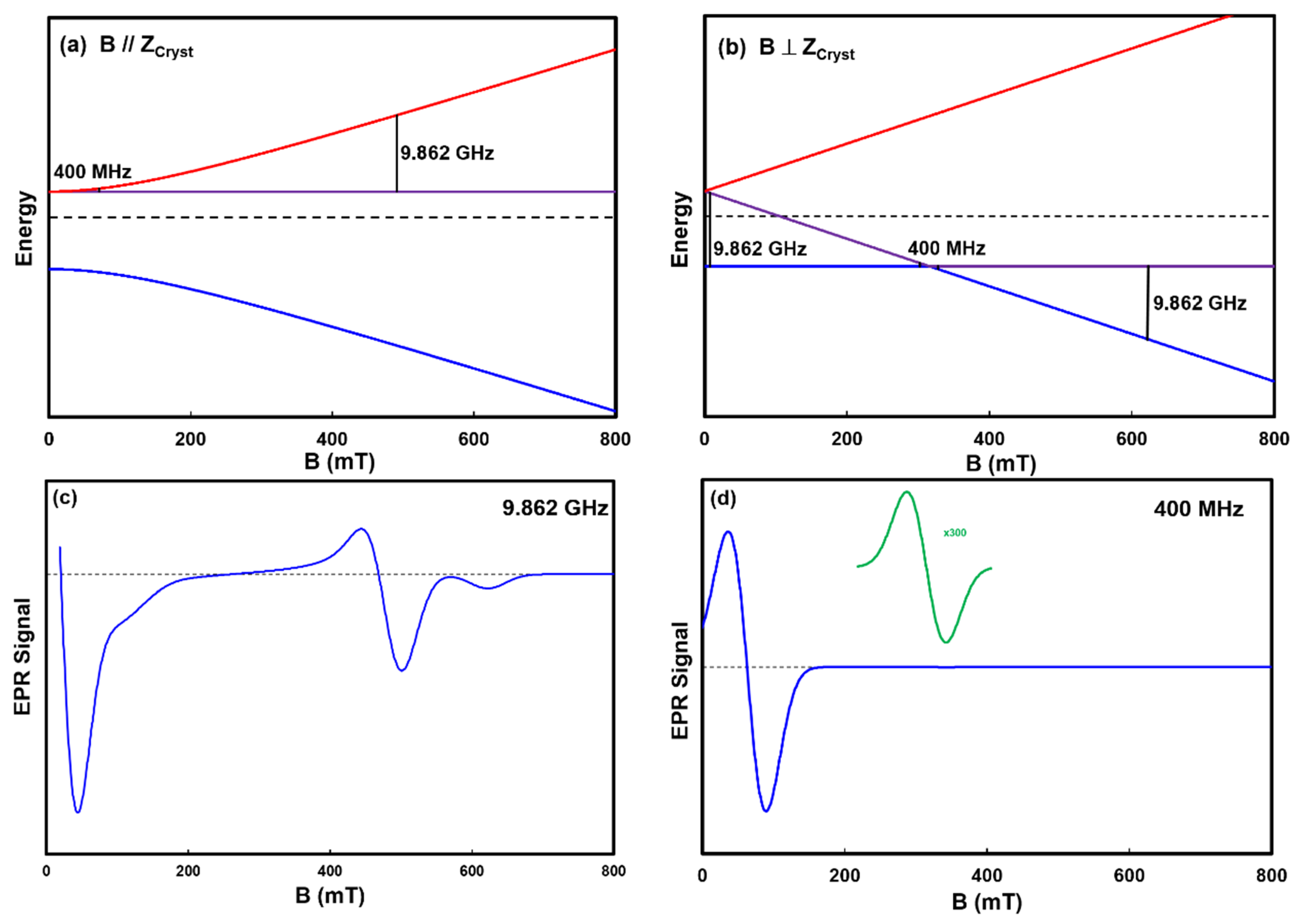
A final model spin system we present is an S = 1 arising from two S = ½ copper ions in close proximity in a crystal lattice. An example of this configuration is copper acetate in verdigris. The energy levels for the configurations with the B field parallel and perpendicular to the Z axis of the crystal are presented in
Figure 5. This system possesses axial symmetry, and as such, exhibits both a g
// and g
⊥ of 2.056 and 2.29, respectively, and the zero field energy parameters D and E of 10.1 GHz and 180 MHz, respectively [
46]. The black vertical lines in the energy level diagrams represent the ΔM
S = ±1 transitions at 0.4 and 9.862 GHz, the former barely visible due to their small size. It is worth noting that the B location of the transition in the simple spin system depicted in
Figure 1a and
Figure 2 scales with ν, as does the transition in the parallel crystal orientation depicted in
Figure 5a; however, the low field transition in the perpendicular orientation depicted in
Figure 5b does not. As ν decreases from 9.862 GHz, the two transitions at 7.5 and 622 mT approach 317 mT.
The EPR spectra in
Figure 5c,d represent the weighted sum of all the possible transitions at all the θ orientations of the crystal particles in the powder. These spectra are predictable with the spectral simulation package EasySpin. The 9.862 GHz spectrum of the model system shows multiple features that compare favorably with those observed in the pigment verdigris that is included in the library. Please see
Appendix A for a more detailed explanation of the spectra.
The simulated 400 MHz spectrum (
Figure 5d) contains absorptions at 31 and 317 mT. The two transitions at 302 and 327 mT appear as one absorption at 317 mT because their separation is less than the linewidth of the individual absorptions. The 317 mT signal is considerably smaller than the 31 mT absorption because it arises from the single θ = 0° parallel crystal orientation. Note that, despite simulating it here, it is not currently possible to actually measure an LFEPR spectrum of verdigris for two reasons. First, the B field sweep width is currently limited to 0 to 50 mT [
29], meaning the absorption at 317 mT is out of range, and second, an absorption at 37 mT with a linewidth this wide will appear as a sloping baseline within the 0 to 50 mT range.
2.4. Limit of Detection
The magnitude of an EPR signal for a transition between two spin states is proportional to the population difference between unpaired electrons in the lower and upper spin states, (N
−) and (N
+), respectively. N
+ and N
− are given by the Boltzmann equation:
where k is Boltzmann’s constant and T the temperature in Kelvin. Equation (2) reveals that (N
− − N
+) is proportional to ν and inversely proportional to temperature. This means the greater the frequency and the lower the temperature, the larger the signal. Once again, lowering the temperature of an object with cultural heritage significance is imprudent if not unallowable.
Spectral noise is composed of thermal, shot, and flicker noise and these vary from spectrometer to spectrometer [
47]. Thermal and shot noise are independent of frequency while flicker noise is inversely proportional to ν. Thus, the EPR signal-to-noise ratio (SNR) is proportional to ν
2 from:
Performing EPR at the highest frequency possible is preferable as the SNR of a 400 MHz EPR will be 0.2% that of an EPR operating at 9 GHz.
In EPR, the absorption peak area is proportional to spin concentration. Therefore, for a fixed spin concentration, the peak height decreases as peak width increases. It should be noted that the spin concentration does not always equal the sample concentration. For example, in the pigment carbon black not every carbon has an unpaired electron. The smallest number of spins which gives a signal discernable above the spectral noise is the limit of detection (LOD) for that spin.
Because the peak height for a constant number of spins increases as linewidth decreases, LOD has a linewidth dependence. The greater the linewidth the greater (poorer) the LOD. To account for this, the EPR LOD is the detectable spins divided by the linewidth and has units of spins per mT. The number of spectral peaks for a sample also figures into the LOD for the sample. All things remaining equal, a sample with two spectral peaks will have a higher LOD than a sample with a single peak because the signal of the former is divided between two peaks.
Although the EPR LOD is useful for determining the number of spins needed to see a signal, determining the number of spins in a sample is not always straightforward, especially when the signal arises from impurities in a sample rather than the main component. In the library, the signal per mass of the pigment relative to the signal per mas of the EPR standard and stable free radical 2,2-diphenyl-1-picrylhydrazyl (DPPH) (S
R) is reported as a measure of relative signal magnitude. It is calculated from X-band data as:
where S
PP is the peak-to-peak signal of the largest spectral absorption and m is the mass.
The S
R value allows estimation of the ability to detect a signal for a paramagnetic sample. For example, if an S
R = 0.5 is the LOD for an LFEPR spectrometer, no pigment with an S
R ≤ 0.5 can be detected. This is further described in
Section 5.
3. Instrumental Details
Commercial EPR spectrometers are available that operate between 1 and 35 GHz. LFEPR spectrometers that operate between 100 and 500 MHz also exist, but generally are not commercially available.
Table 1 lists the approximate frequency, descriptor, and SNR relative to the X-band based on the operating frequency of typical instruments.
It is important to reiterate that the maximum sample size in X-band EPR is limited by the approximate 0.2 cm3 active volume of the sensor in which it must be placed, making it an invasive analytical technique requiring sampling. The EPR MOUSE, however, is a surface analysis instrument which examines a sample volume of 0.015 cm3 on the surface of any size object from a ceramic shard to a large wall size mural, and is therefore, noninvasive.
Several acquisition parameters can be adjusted to optimize an EPR spectrum. The applied magnetic field (B) is swept from BMin to BMax at NPts increments over a time tS. The sweep width (BSW) is BMax − BMin. The dwell time (δτ) is the time spent at each magnetic field value during a field sweep and is equal to tS/NPts. The sweep rate is BSW/tS and the sweep resolution is BSW/NPts.
The time constant (RC) is the time it takes for the signal to change by a factor of e. The time constant should be selected with the sweep rate and the smallest spectral feature in mind. If RC is too large for the sweep rate, spectral absorptions will be distorted. In general, a large RC and small sweep rate will remove high frequency noise from a spectrum. Another way to remove random noise from a spectrum is by averaging the NAvg spectra together as the SNR is proportional to (NAvg)½.
The applied magnetic field is modulated at a frequency (fMod) between 10 kHz and 100 kHz and the signal is phase sensitive detected at this modulation frequency to improve the SNR of the spectrum. The modulation amplitude (BMod) should be less than the peak-to-peak linewidth (ΓPP) of the signal to avoid absorption peak distortion, but it can be greater than ΓPP if improving the SNR is the main goal.
Often, post processing of a spectrum is also performed to improve the SNR. The goal in post processing is to improve the SNR and appearance without distorting the spectral line shapes or Γ
PP. The reader is directed to one of the many texts on the practical aspects of EPR for more detailed information [
39,
40,
48].
4. The Library
The open-access library is available at
https://www.cis.rit.edu/htbooks/epr-pl/ on either desktop or mobile devices; the vertical page layout ensures that it is easily navigable using either kind of device. The reader is encouraged to reference this section while simultaneously following along with an entry in the library in order to actively gain an understanding of the presentation of the information therein. In cases where it is not possible to simultaneously access the library, an example library entry can be found in
Appendix B.
The spectral library currently contains entries for 51 pigments and colored compounds of significance in cultural heritage science. These entries are organized on the main page in two different ways; first, in sections based on color, and second, alphabetically by common name. The main page also contains links to a Preface and Help page, to assist users in utilizing the library, as well as a List of Terms and Abbreviations, which defines the terms and symbols used throughout the entries.
Each entry in the library is organized in the same way. The page is titled with the common name of the pigment or compound, followed first by other identifiers and physical properties. These are organized into an Other Names table, and a Physical Data table. Where available, Other Names lists all of the following: the pigment serial number and Color Index number, the chemical name, colloquial names, and equivalent natural minerals. In particular, the pigment serial number and Color Index number are unique identifiers that specify the exact substance of interest. This is important because there are instances in which pigments having the same hue, but which have been manufactured with a different chemical makeup than the real pigment, are marketed using the same name as the real pigment. The chemical name is used to indicate the oxidation state of the main transition metal ion in the substance, if applicable. The colloquial and mineral names are useful in cases where different disciplines may refer to a substance differently.
Physical Data lists the source of the sample, its chemical formula, the g-factor, and ΓPP. A sample was sourced based on its chemical formula and not hue, (e.g., natural and synthetic ultramarine were acceptable whereas the ultramarine hue pigment, matching in color but not chemical makeup, was not). The source of the sample, whether it be a pigment manufacturer, a chemical supplier, or a natural source, can also give insight into the presence or absence of certain impurities. The X-band samples were approximately 50 mg and the LFEPR samples 20 mg. For example, many naturally occurring iron earth pigments will contain trace amounts of other metals, particularly manganese, which is apparent in the spectra of many of these pigments. The chemical formula shows how many ions of the elements of interest are present per unit of the substance. Because the g-factor is a constant that is unique to the environment of the electron, it can be considered a fingerprint feature in EPR and when included in the table, nearly all of the g-factors provided are cited literature values. When the g-factor that is listed was instead estimated from the X-band spectrum collected for the library, this is noted. ΓPP values were exclusively measured from the X-band spectra presented in the library and are noted as such. In cases where the spectrum displays an intricate absorption pattern, this is acknowledged. For some, the absorption was deemed most prominent, and from which the ΓPP was measured is stated. Still other pigments that were studied had no literature precedent and displayed line shapes too complex to measure for either the g-factor or ΓPP, which is also noted.
The next section of each entry displays the spectral data and associated acquisition parameters. Every entry contains an X-band (9 GHz) spectrum. Many also have an LFEPR spectrum (~400 MHz), and a select few have an intermediate, L-band spectrum (1 GHz) and/or a Q-band (35 GHz) spectrum. All the Q-, L-, and X-band spectra were recorded from neat powders. The LFEPR spectra were recorded from both neat powders and powders in set linseed oil. Both the X-band and LFEPR spectra have detailed accompanying tables of Acquisition Parameters. Fewer details are available for the L-band and Q-band spectra. These are reported more as supplemental spectra that are of interest for observing changes in the appearance of the recorded spectrum as a function of frequency and typical sweep width at that frequency (note the typical sweep widths associated with each frequency: 950–1350 mT for Q-band spectra, 0–600 mT for X-band spectra, 6–66 mT for L-band spectra, and 0–50 mT or 0–35 mT for LFEPR spectra). For some pigments, a second “zoomed-in” X-band spectrum is provided that shows spectral details. These auxiliary plots are provided to enable better visualization of the spectral absorptions with narrow line widths or other features that are otherwise difficult to discern in the full sweep.
The X-band Acquisition Parameters table lists the essential instrumental parameters used, post-processing techniques applied, and relative signal per mass (SR). Stating the tuned operating frequency (ν), number of spectral points collected (NPts), time constant (RC), sweep time (tS), modulation amplitude (BMod), and modulation frequency (fMod) enables replication by others. Similarly, stating the post-processing techniques applied to the spectra, which to this point have included only simple baseline offsets or sloping baseline corrections, provides insight into the possible differences in appearance between raw and corrected spectral data. Furthermore, some spectra are the result of several sweeps that were averaged to improve SNR. Finally, SR, which is the relative metric by which the signal magnitude is reported throughout the library (Equation (4)), is provided as a measure of the ability to resolve a signal. The SR values were calculated using the most prominent absorption in the X-band spectrum and indicate the magnitude with respect to that of the DPPH standard. The magnitude of the SR value serves as a useful metric with which to compare the relative signal intensities.
The LFEPR Acquisition Parameters table lists the same instrumental parameters and post-processing procedures applied. It also includes a System entry, which specifies which of the subsystems of the LFEPR spectrometer was used to collect the spectrum: the single turn solenoid (STS) [
28], or, more frequently, the MOUSE.
The Notes and References section provides citations of the literature sources from which the g-factors listed in Physical Data were referenced. Exhaustive efforts were made to procure sources in which the pigments had been previously studied, but a precedent does not appear to exist for many of these substances. In these cases, where the g-factors and/or ΓPP values were measured from the X-band data, footnotes stating this appear here, sometimes with details about which spectral absorption the estimated values pertain to. For some pigments, this section also contains footnotes describing the unique features observed in the spectra, for example, evidence of the presence of ferromagnetism.
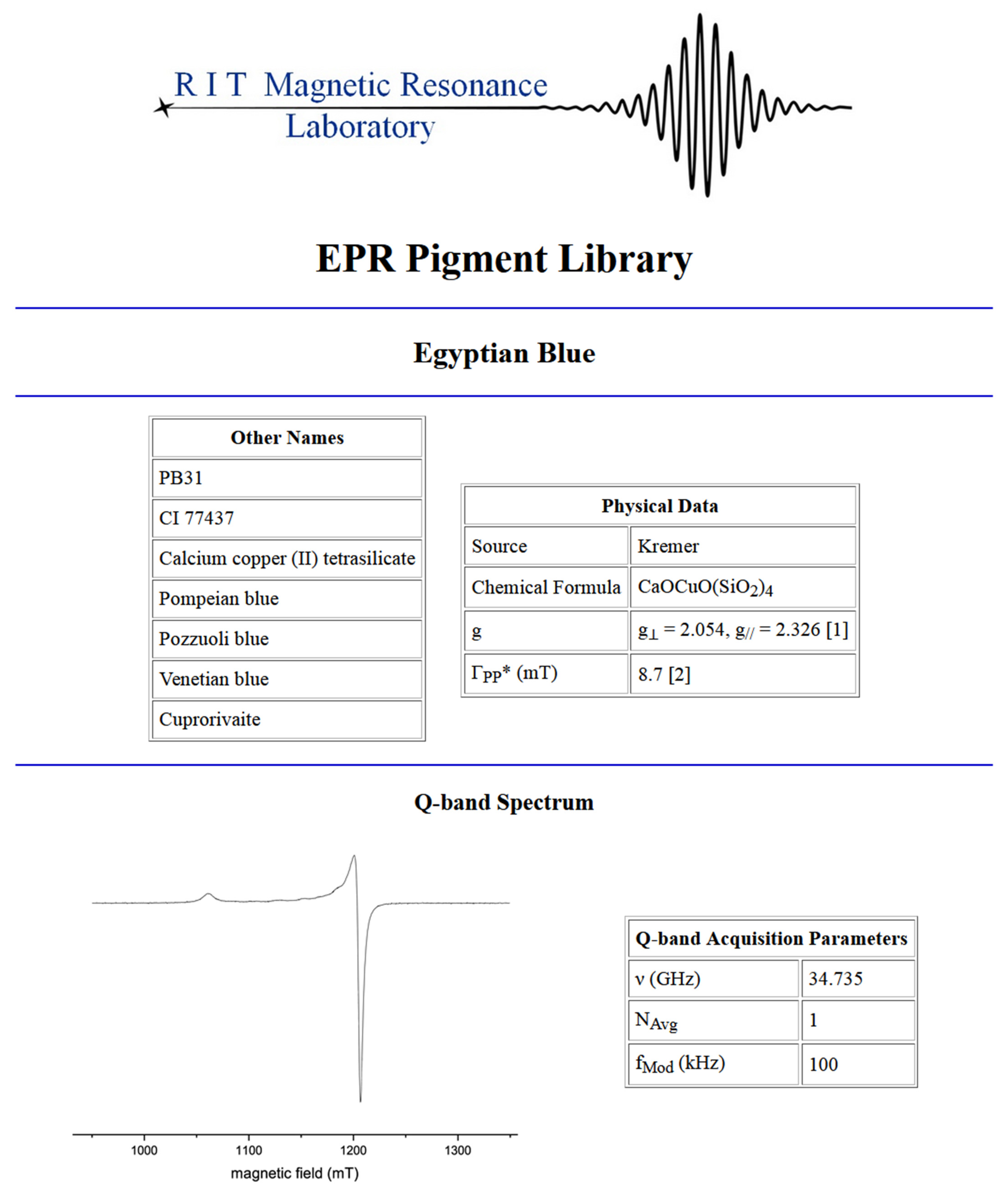
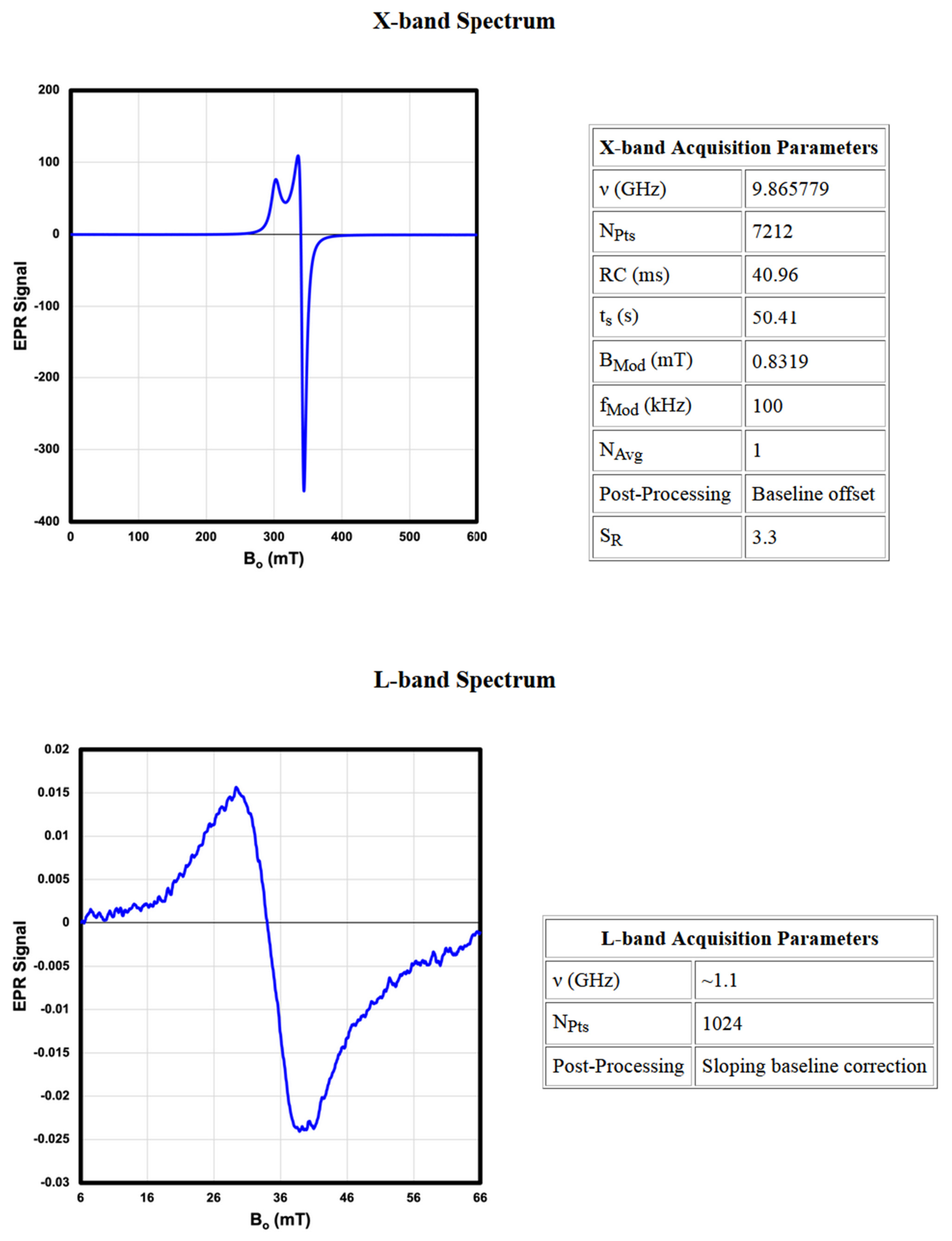
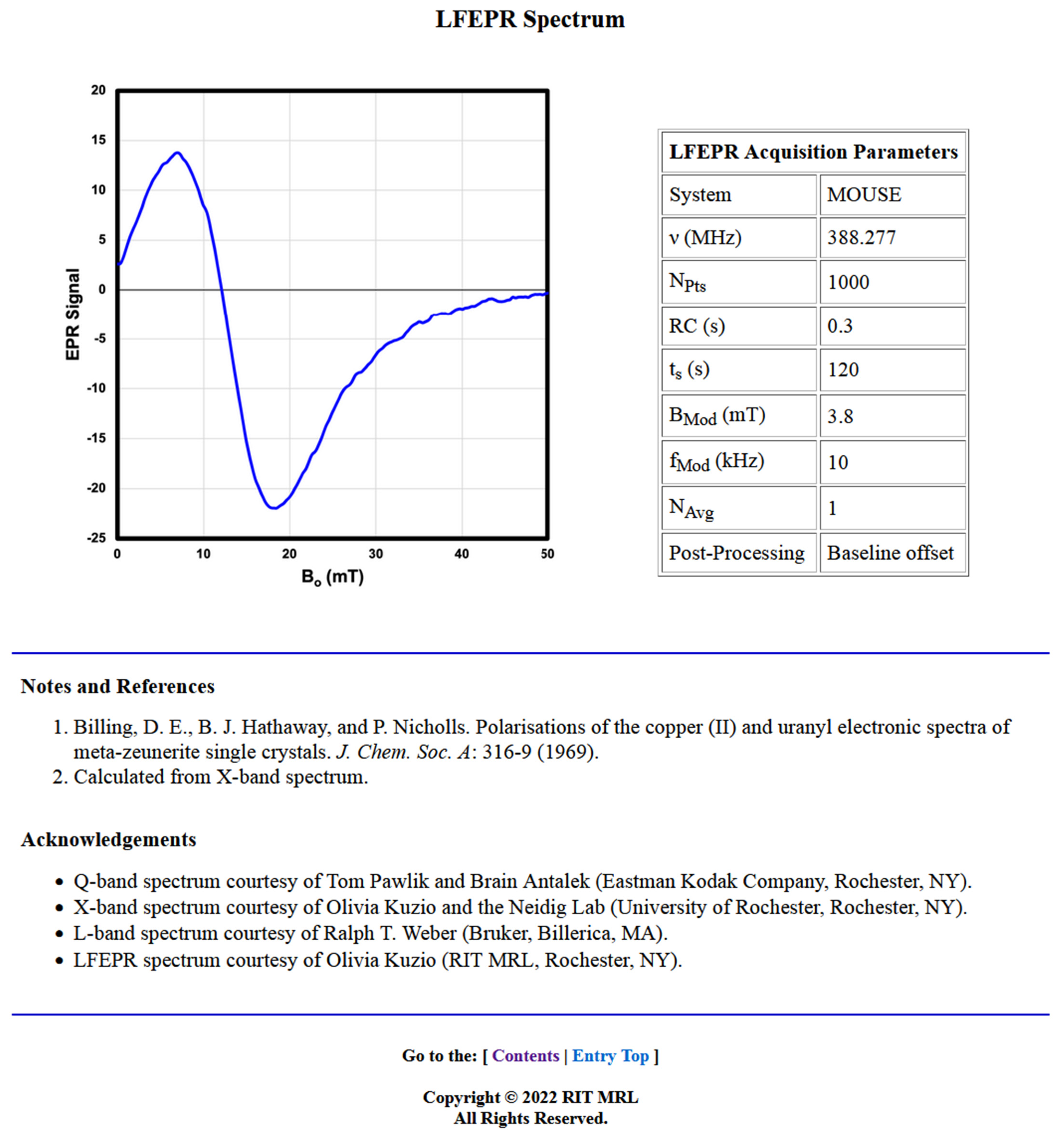
An example of a library entry for the pigment Egyptian blue (
Appendix B) exemplifies nearly all of the features of the library discussed in this section, including spectral data collected at all four spectrometer operating frequencies.
The objective in making available the library as it exists now was to create a database that can be used to visually reference other spectra against. The present intent is not to interpret the spectra. EPR signals and their origin can be an intricate puzzle, especially when considering the nature of pigments procured from natural sources, sometimes with several components giving rise to various spectral features. While the signals that arise are predictable and identifiable, the interpretation of the spectra that they coalesce into is left as an exercise for the more advanced reader using EasySpin. The library’s value lies in its availability and breadth, where previously, such a reference collection for the EPR of artists’ materials did not exist. It is intended to be a living repository. As other EPR-active pigments are acquired, their spectra will be added to the library. Additionally, as future hardware enhancements are made to the MOUSE that enable the collection of LFEPR spectra with, for example, wider sweep widths and/or improved SNR, the current library entries will be revised to include this improved spectral data.
5. Practical Considerations for Pigment Identification by EPR
A description of the practical considerations for using EPR as a diagnostic tool in pigment identification is provided in the following comparative example.
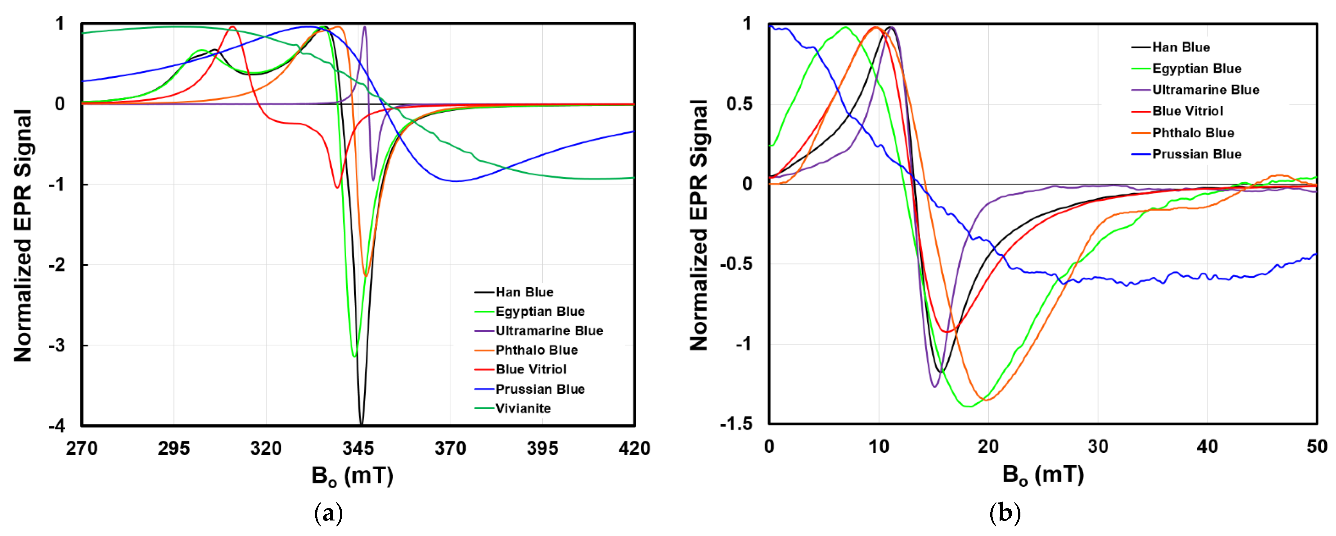
Figure 6 presents the X-band and LFEPR spectra of a selection of blue pigments included in the library. The spectra have been normalized to facilitate their comparison on common sets of axes. Additionally, the values of the relevant diagnostic features of the g-factor and linewidth are provided in
Table 2.
The X-band spectral line shapes of the seven pigments are distinct. For example, Han blue, Egyptian blue, and phthalo blue display characteristic powder pattern spectra for spins with axially anisotropic g-factors; their spectral shapes are comparable to that introduced in the top left plot of
Figure 4. Among these three, Han blue and Egyptian blue, which are isomorphs that differ by the presence of either a Ba(II) or Ca(II) ion, respectively, exhibit similar shape characteristics but distinct g
⊥ and g
// values. Note that the powder pattern line shape for phthalo blue is narrower than that for Han and Egyptian blue because the difference between g
⊥ and g
// is smaller. Meanwhile, the spectra of ultramarine blue, Prussian blue, and vivianite display line shapes consistent with systems possessing isotropic g-factors. Finally, blue vitriol possesses a line shape unlike the others, exhibiting a signal with separation between its positive and negative lobes.
Visual comparison of the differences in the spectra are quantified by the linewidth and g-factor(s) (
Table 2). The linewidths range over two orders of magnitude, from the 2.3 mT-wide absorption of ultramarine to the 113.3 mT-wide absorption of vivianite. Note that in anisotropic systems, Γ
PP and S
PP were measured based on the g
⊥ part of the spectrum.
While the major absorptions of this group of pigments exhibit g-factors of approximately two, their precision is often reported to six decimal places in the literature and are thus distinguishable by this metric. As an example, Han blue, Egyptian blue, and phthalo blue, with their similar powder pattern spectral shapes and linewidths, possess distinct g-factors.
Still other features that arise due to a peculiarity within a pigment can be useful in its identification. For example, as mentioned above, the characteristic spectral shape of blue vitriol arises due to exchange coupling between inequivalent octahedral Cu(II) centers unique to this chemical environment [
49]. In another case, the spectrum of vivianite shows evidence of a natural Mn(II) impurity by the presence of the sextet absorption pattern centered around approximately 350 mT.
The prominent observation in the LFEPR spectra is the loss of powder pattern spectral detail, as discussed with respect to
Figure 4. Because of this, it may appear that LFEPR spectra contain little spectral detail of diagnostic utility; however, subtle differences that distinguish the spectra, while not visually obvious, are detectable by algorithm-based approaches that have been shown to be capable of distinguishing single pigments and two-component mixtures [
33].
Vivianite does not appear in the plot of the LFEPR spectra because the 113.3 mT linewidth of its signal is too broad to be adequately captured by the current MOUSE. At present, the MOUSE provides a sweep width of 52 mT. Therefore, the evidence of the vivianite signal over this range has the appearance of a sloping baseline. Without the ability to record the turning points of the signal’s 113.3 mT linewidth, the recorded spectrum lacks diagnostic features. For this reason, at present, the LFEPR spectrum of vivianite and other pigments displaying linewidths too broad to be adequately captured within the sweep width of the current LFEPR instrumentation are not included in the library; however, the LFEPR spectrum of Prussian blue is included both in
Figure 6 and in the library. Evidence of its 39.7 mT-wide absorption is apparent in the shape of the spectrum, which shows an increasing intensity again after about 35 mT. These observations are consistent with its larger linewidth relative to those of the others. Consider, also, the relative SR values of vivianite and Prussian blue, which differ by an order of magnitude. For the same analytical volume examined by the current MOUSE, the signal of vivianite is ten times smaller in magnitude than that of Prussian blue, and below the LOD of the current hardware.
The observations about large-linewidth and small SR pigments necessitate emphasis that the library is a living database. LFEPR spectra will continue to be added as hardware improvements enable the recording of diagnostic signals for pigments such as vivianite which currently are not identifiable by LFEPR.
This section highlighted the differences between the spectra of a group of blue pigments and described how the specific features associated with these differences can be used for pigment identification. EPR spectra are rich with information that can be used for characterization, especially when considered in combination with information provided by other analytical techniques. For example, this group of blue pigments may prove challenging to differentiate, let alone identify, purely based on visible reflectance; however, as shown above, the features that make EPR spectra distinct, particularly the g-factors, provide the necessary specificity. EPR, therefore, is an excellent candidate for inclusion in a comprehensive suite of analyses for technical heritage studies. No one analytical technique is yet a turnkey method, especially considering the complex systems of real artworks and artifacts with pigment layers, mixtures, and impurities. These complexities continue to require human input for full interpretation.
6. Conclusions
An EPR spectral library of artist’s pigments has been created, and the principles of EPR that are necessary to understand many of the diagnostic features present in the spectra have been described. With this reference database and an understanding of its contents, conservation scientists are equipped to utilize this spectroscopic technique to study and identify a variety of pigments found in heritage objects. Though currently underutilized in the field of conservation science, the creation of the library, and the intent that it be a living repository that will grow as EPR is used to study more pigments, serves as a foundational step toward establishing EPR as a powerful tool with which to supplement pigment analysis. Especially as the capabilities of LFEPR continue to advance, and this technique becomes more sensitive and more portable, the library reflecting these advancements will deepen as a useful collection for reference.
