1. Introduction
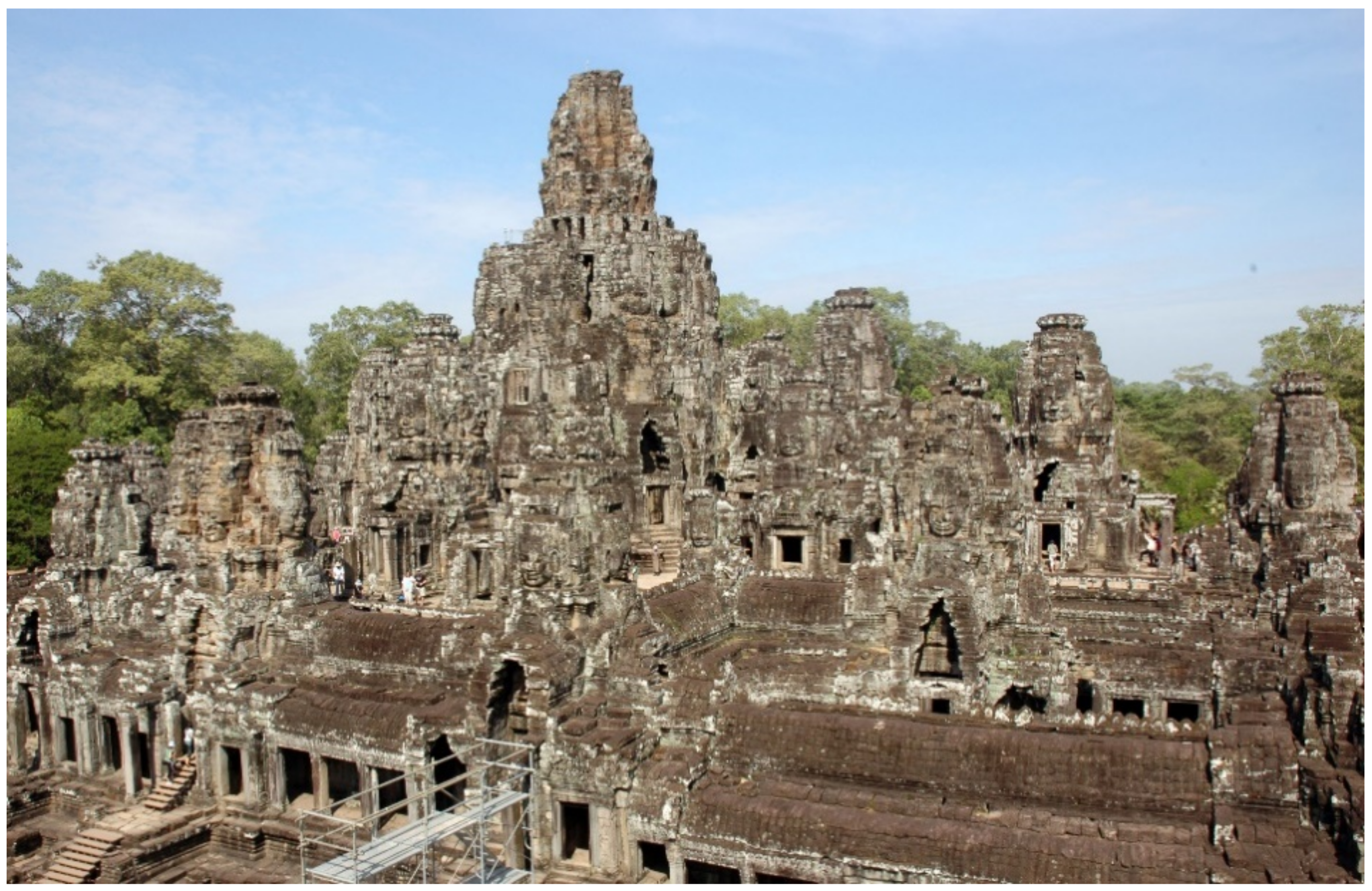
Bayon Temple was built as a state temple of the Angkor Empire in the center of the royal capital of Angkor Thom in the latter half of the 12th century by Jayavarman VII, the ruling king at the time. The temple is doubly enclosed by two galleries, and at its center is a central terrace that is approximately 5.5 m high and has a cruciform ground plan (
Figure 1 and
Figure 2). The terrace can be accessed by a total of five steep flights of stairs, two on the east side and one each on the other three sides of the terrace. On the terrace stands a group of towers, which includes the central tower that rises to a height of 31 m from the floor of the terrace, eight sub-towers surrounding the central tower, and four annexed towers to the east of the central tower and sub-towers, in addition to six more independent towers.
The Japanese Government Team for Safeguarding Angkor (JSA/JASA; Director General: Takeshi Nakagawa) commenced restoration work at Bayon Temple in 1994 and has undertaken the restoration of the northern library, which was at high risk of collapse, the southern library, and part of the outer gallery, to date. Aside from engaging in the restoration of these buildings, it has also carried out surveys for evaluating the structural stability of the central terrace and the central group of towers.
A part of the upper masonry of the central tower, made of a dry masonry of sandstone blocks, collapsed in 1932 and was subject to strengthening work by l’École Française de d’Extrême-Orient (EFEO) in 1933. The strengthening materials that were used at the time have deteriorated, however, such that it has become necessary to consider conducting a re-restoration. Behavior measurements and structural analyses of the masonry of the central tower that have been conducted by JSA/JASA so far show no signs leading to the collapse of the tower [
1,
2,
3,
4]. In addition, based on the structural analysis of the central group of Towers of Bayon, there is little risk of these collapsing immediately [
5,
6,
7]. However, with the Angkor monuments, there have been cases where stepped pyramid-shaped temples such as Angkor Wat and Baphuon have suffered large-scale collapse due to heavy rain and other such weather conditions, so it must be noted that sudden collapses are difficult to predict. In particular, any partial collapse of the central terrace could bring about devastating damage to the upper structure, so careful surveys and diagnosis are required.
The walls and floor of the central terrace are also made of a dry masonry of sandstone blocks, but the inner structure has remained unknown. Classic-period temples of Angkor with high platform structures typically had a laterite retaining wall and compacted soil inside the sandstone wall, so the central terrace of Bayon was also assumed to have the same type of multiple layered structure.
Archaeological surveys of the structure inside the central terrace directly below the central group of towers were conducted twice in the past by EFEO. The first was an excavation at the chamber inside the central tower following the abovementioned reconstruction work on the central group of towers, conducted by Trouvé in 1933 [
9,
10]. In this survey, a vertical hole was dug down to a depth of approximately 14 m below the floor surface of the central tower, along a looted pit that was made in the past. Inside the hole, groundwater rose to a depth of 12.5 m, so the excavation survey was ended without digging the hole down to the bottommost level of the looted pit. From this hole, a stone statue of a seated Buddha measuring as much as 4.7 m in height, including the pedestal, was discovered broken into multiple fragments. It is thought to have been the central idol of the Bayon Temple. Along with other significant artifacts that have been unearthed, it provides an important clue to studying the history of the temple [
11]. At a depth of 12.5 m in the hole, an additional excavation was carried out by digging horizontal holes toward the east, west, and south. By digging these horizontal holes, several sandstone blocks were found and the strongly compacted embankment was confirmed at the end of horizontal hole [
12]. This survey clarified the approximate area of disturbed soil by the past looting. After suspension of this survey, the excavated hole was backfilled to a depth of 2 m from the floor surface of the chamber, and an opportunity to carry out a re-examination by digging down to the bottommost surface of the looted pit was awaited. Although the additional survey was not realized due to the death of Trouvé, who oversaw this research project, the remaining 2 m up to the floor surface were backfilled by Marchal, the next conservator.
The second archaeological survey was carried out for identifying the foundation structure of the 12th tower, which is located at the east side of central tower, conducted by Marchal in 1937 [
13]. A five-tier laterite structure, measuring about 1.2 m thick, was confirmed below the sandstone blocks of the floor surface, but the structure was asymmetrical between the north and south. A compacted soil layer mixed with gravel continued below the laterite structure, and the survey was ended after digging down to a depth of 6.3 m. A multiple number of sandstone blocks were confirmed haphazardly mixed in the soil at a depth of 3 to 4 m from the floor surface. These two previous surveys of the inside of the terrace provided valuable information on the foundation structure of central group of towers, but the scope of these surveys was limited to evaluate the stability of this structure.
To shed light on the foundation structure inside the terrace, JASA conducted an electrical resistivity survey, frequency domain electromagnetic (EM) survey, and underground radar exploration in 2007 [
14,
15]. From these surveys, a relatively shallow portion of the inside of the central terrace was assumed to have partially loose planes and slip planes, in addition to areas with high water content ratios. However, there was a limit to the analysis precision, and the surveys did not reach the structure in the central portion of the terrace. For these reasons, a series of archaeological and geotechnical surveys were carried out to elucidate the inner structure of the platform by conducting an excavation survey in the chambers of the central group of towers, and a geotechnical boring test with the minimum possible diameter.
2. Aim of the Research
One of the scenarios envisioned regarding the collapse of the central group of towers at Bayon Temple involves the deformation and collapse of the central terrace. Thus, to evaluate the risks of collapse accompanying the deformation and collapse of the central terrace, an examination was carried out with the objective of shedding light on the inner structure of the terrace. Another objective was to confirm the soundness of the inner structure of the terrace, including the condition of the soil that was backfilled after a previous excavation surveys, and expose any destabilizing factors. This research aimed to evaluate the foundation structure and stability of the central group of towers to acquire concrete information for discussing the necessity and methods of intervention, including structural strengthening for preserving the central group of towers for a long term hereafter.
3. Examination Method
To shed light on the inside of the central terrace, and particularly the foundation structure directly beneath the central group of towers, archaeological excavation work was conducted in the chamber of the central tower and the chamber of the 6th tower, which is a sub-tower on the west side, in 2008. In the chamber of the central tower, the sandstone blocks of the present floor surface were dismantled, and backfill soil from past surveys was removed down to a depth of 2.25 m from the floor level. In the 6th tower, archaeological excavation work was conducted down to a depth of 2.5 m from the floor level.
From the bottommost level of the excavation work in the central tower, a preliminary boring test was conducted using a manual drilling tool, a hand auger (BYC1-2008) (
Figure 2). A hole was drilled down to a depth of 8.41 m from the floor surface, and compacted soil was sampled from each level to analyze the water content ratio and grain size distribution. In 2009, a machine boring test was conducted in the same spot (BYC2-2009). A hole was drilled down to a depth of 19.5 m from the floor level, and compacted soil was sampled from each level to analyze the water content ratio and grain size distribution. A standard penetration test was also performed.
In 2010, a machinery boring test was conducted at three spots from the top surface of the central terrace. One borehole was drilled vertically to a depth of 18.5 m (BYV-2010), one was drilled diagonally down to a depth of 18.5 m at a 30-degre angle toward the central towers (BY30-2010), and one was drilled diagonally down to a depth of 9 m at a 45-degree angle (BY45-2010). In the vertical boring of BYV-2010, compacted soil was sampled from each level to analyze the water content ratio and grain size distribution, and a standard penetration test was performed. After the boring test, a water gauge was attached to the boreholes to measure the groundwater level in the hole of BYV-2010.
In 2012, an additional machinery boring test was conducted in the horizontal direction from two spots on the side of the Central Terrace. One borehole was drilled at a length of 16.4 m from the north side of the terrace (BYHN-2012), and the other was drilled at a length of 16.2 m from the south side of the terrace (BYHS-2012). In all machine boring tests, cores with diameters of 6.5 cm were extracted for visual observation.
4. Result
4.1. Result of the Archaeological Excavation in the Central Tower and 6th Tower
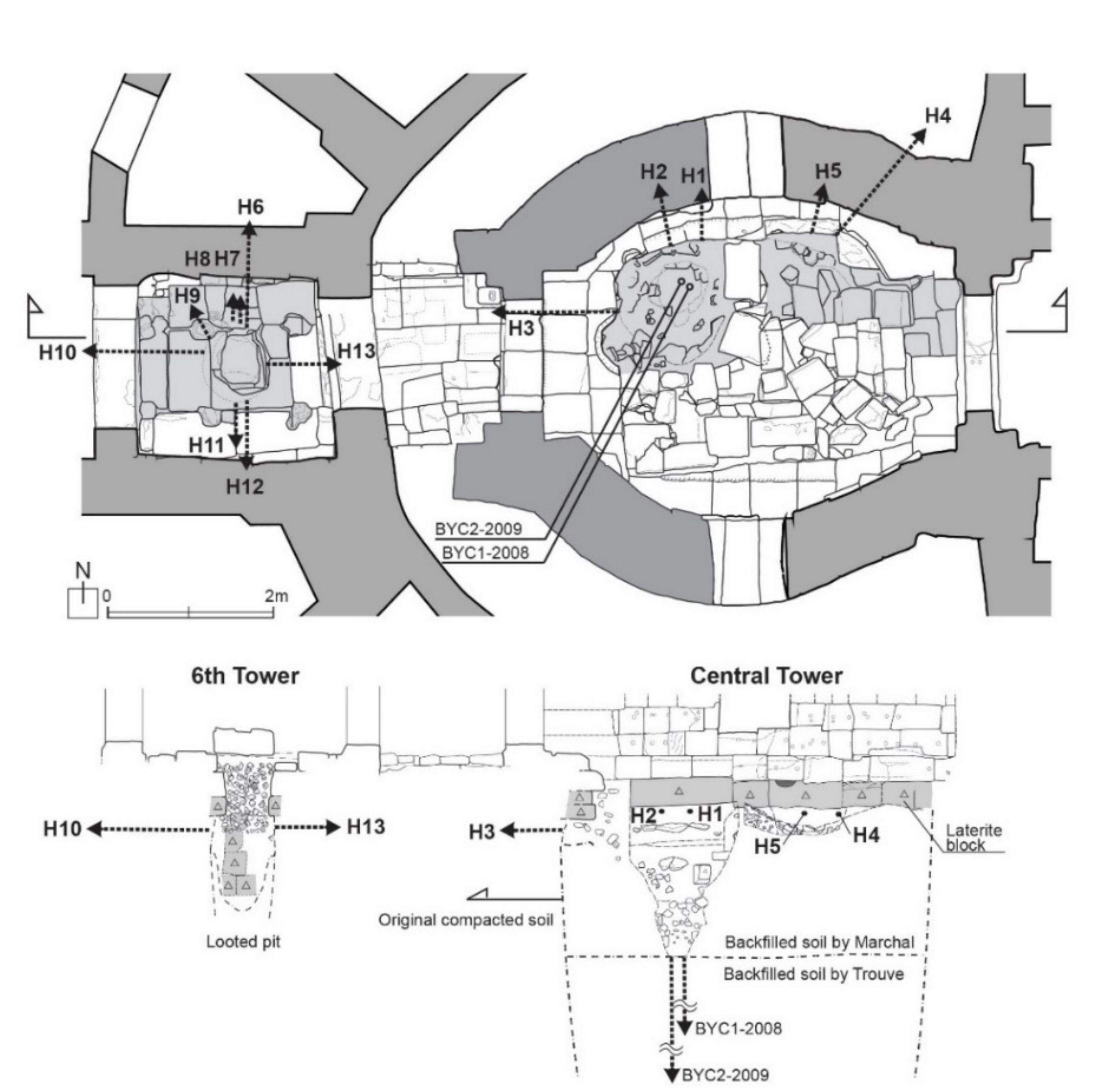
The chamber of the central tower has an oval plan that is long in the east–west direction. The existing sandstone pavements in the north half of the chamber were dismantled and excavation work was conducted by digging down to a depth of 2.25 m from the floor level (
Figure 3). The soil that was backfilled after a survey conducted in the 1930s appeared from below two layers of sandstone blocks. The backfill soil was 2.25 m deep, dark brown in color, and contained a large amount of sandstone cobble (20–30 cm in diameter). It was also low in density and had many cavities. Buried in the soil were large numbers of modern-era ceramic fragments, glassware, ironware, and other such items [
16]. The sandstone cobble clearly differed from the gravel contained in the compacted soil, the presence of which was previously confirmed in other areas at Bayon Temple, so it was presumed that the filling material was collected from the vicinity of the central tower. The soil layer below 2.25 m was composed of sandy soil containing little gravel, and it distinctly differed from the upper layer. Thus, it is thought that the soil layer below 2.25 m consisted of soil that was temporarily backfilled when the survey was suspended in the 1930s, and the upper soil layer consisted of soil that was backfilled thereafter by Marchal. No further excavating was attempted below 2.25 m, as it was deemed dangerous to do so.
By removing the upper layer of backfill soil, it became possible to observe the structure directly beneath the floor level of the north wall in the chamber. A layer, or two layers in some places, of laterite blocks approximately 30 cm thick was confirmed paved below the bottommost sandstone blocks of the wall (
Figure 3). The laterite blocks were brittle on the surface and roundish. It was assumed that they were exposed during a past survey or during a looting and had progressively weathered. Brown, sandy compacted soil was confirmed below the laterite layer. It contained gravel that was approximately 20 cm in diameter from conglomerate rocks and a thin 3–5 cm layer of silty clay, and was estimated to have a bearing capacity of roughly 800 kPa when measured using a Yamanaka soil hardness meter. To verify the existence of a stone support structure directly beneath the wall, a hand auger was inserted horizontally at the level below the laterite layer in a total of five spots. In three spots (H1, H2, and H5), the hand auger came up against gravel and the drilling was stopped, but in two spots (H3 and H4), the hole was able to be drilled through to the adjacent chamber from beneath the wall. In other words, there was no masonry structure beneath the wall of the central chamber to directly support the wall.
At the 6th tower, an excavation was conducted down to a depth of approximately 2.5 m from the floor level. As at the central tower, laterite layers were found below a pavement of two sandstone layers. There was a maximum of five layers of laterite in some places, arranged in irregular fashion. This feature resembled the structure of the laterite layers beneath the bottom layer of the wall that was confirmed in an excavation conducted in the chamber of the 12th tower in 1937. The compacted soil beneath the laterite layers was examined by horizontally inserting a hand auger at a total of eight spots (H6–H13). At most spots, the drilling was blocked by gravel that was mixed in the compacted soil. However, at the survey spot where the hand auger was inserted horizontally toward the north side (H6), the hole penetrated the soil beneath the wall. Therefore, it was confirmed that no masonry support structure existed directly beneath the wall, as was found in the central chamber.
4.2. Result of the Boring Test Using a Hand Auger in the Central Tower (BYC1-2008)
A boring test using a hand auger was performed from the bottommost level of an excavation carried out in the northwest area of the central chamber. A hole was drilled to a depth of approximately 6 m from the bottommost level of the excavation pit and 8.41 m from the floor level. It was perceived from the manual drilling that the backfill soil continued on in a considerably loose condition. The soil was collected from each level to analyze the water content ratio and grain size distribution. As a result, a gradual change was seen in water content ratio and grain size distribution between depths above and below 6.5 m from the floor level (altitude of 30.5 m) with the exception of 5 to 6 m. As shown in
Figure 4, water content ratio was roughly 14% to 20% in the upper layers above 6.5 m from the floor level, but less than 10% in the lower layers below 6.5 m. Grain size distribution was such that coarse grains were mixed in the upper layers, but relatively uniform grains constituted the lower layers (
Figure 5). The soil in the lower layers was similar to the compacted soil inside the platform of the northern library at Bayon, which was restored in the past [
17], although it contained fewer fine grains. From this result, it was surmised that the lower layers of the backfill soil contained original compacted soil from the 1930s and the upper layers constituted backfill using a different soil.
4.3. Results of Machine Boring Tests
4.3.1. Vertical Boring Test in the Central Chamber (BYC2–2009)
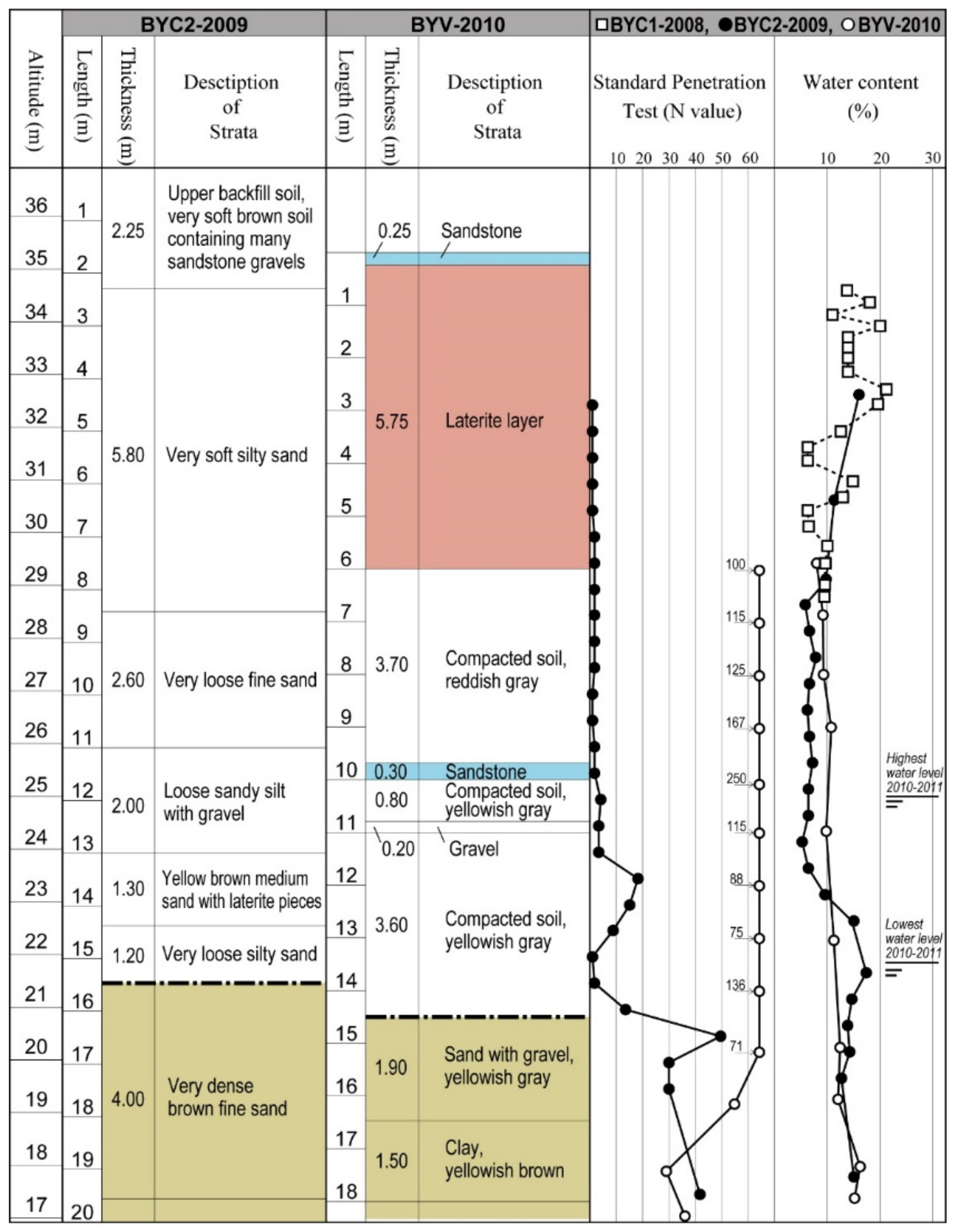
A machine boring test was conducted in the central chamber in March 2009. Down to a depth of 8.41 m, a borehole was drilled parallel to the above-mentioned hand auger hole. At a depth near 19.5 m from the floor level, the drilling was stopped, as the rod became unable to penetrate the soil. Midway, the drilling proceeded without hitting any sandstone or laterite blocks, and mainly fine sandy soil was sampled (
Figure 4). A standard penetration test was performed every 50 cm below 4 m, with the number of blows to penetrate 30 cm recorded as the N-value. Additionally, soil was sampled at a depth of every 50 cm to record the soil characteristics and analyze the water content ratio.
The N-values were extremely low down to a depth of 13 m (altitude of 24 m), and the backfill soil was noticeably loose. At a depth of 13–14.5 m, there was a topical increase in the N-value, and laterite chips were found mixed in the sampled soil. At 14.5–15.1 m, the N-value dropped once again, then rose drastically at depths below 15.5 m. As the excavation conducted in the 1930s presumably did not reach down to the natural ground, it was thought below the backfill soil there is soil that was disturbed during a looting in the past, followed by original compacted soil, and the natural ground, in this order. No clear differences among these soil layers were confirmed in the observation of the quality of the soils collected in the boring test, but it is assumed that the soil down to a depth of 13 m is was backfill soil from a past excavation survey, the soil at depths below 15.5 m that exhibited high N-values is the natural ground, and between the two is a layer of soil that was disturbed during a looting.
Figure 4 shows the water content ratios of soils sampled in the hand auger and machine boring tests conducted in the central chamber. The hand auger test was conducted during the rainy season, in August 2008, and the machine boring test was conducted during the dry season, in March 2009. Although the seasons differed, the water content ratio at depths of 4–8 m (altitude of 29–33 m) was practically the same in both tests. This showed that there is no change in the water content of the backfill soil between the rainy season and dry season, at least at that level. The water content ratio of the soil sampled in the machine boring test was around 6% down to a depth of 13 m (altitude of 24 m), but surged to around 15% below that. As of March 2009, it is presumed that the groundwater level is at around a depth of 14 m (altitude of 23 m).
4.3.2. Vertical Boring Test from the Top of the Central Terrace (BYV–2010)
Between October and November 2010, a vertical boring test (BYV–2010) and two diagonal boring tests (BY30–2010, BY45–2010) were conducted from the central terrace on the south side of the central group of towers. The vertical boring was 18.5 m long and roughly corresponded to the bottommost level of the machine boring that was conducted in the central chamber (
Figure 4). Below the 25 cm-thick sandstone pavement, there was a 5.75 m-thick laterite layer down to a depth of 6 m. The individual size of laterite blocks were 21 to 41 cm thick and around 25 cm on average. They were brittle and porous as a whole, and were thought to have high water permeability.
At depths from 6 to 14.6 m, the compacted soil consisted mainly of uniform grains of sand. This soil differed from the compacted soil in the platform of the southern and northern libraries of Bayon that were restored in the past, which was made up of alternating layers of a clayey layer mixed with laterite chips and a sandy layer.
Depths from 6 to 9.7 m consisted of compacted soil having an upper layer that was pale red–gray in color and composed mainly of uniform fine sand. The bottom layer was composed mainly of a uniform, fine sandy layer, and was stratified with thin layers of medium-grain sand in between. Depths from 9.7 to 10 m consisted of sandstone gravel. Depths from 10 to 10.8 m consisted of compacted layers of pale gray, fine- to medium-grain sand. Below this was a pale brown–gray layer of sandstone gravel 20 cm thick. A fine sand layer of compacted soil further continued down to depths from 11 to 14.6 m.
Depths below 14.6 m were layers of natural sediment. A dark gray sand layer 1.9 m thick was confirmed, mainly composed of fine- to medium-grain sand mixed with sandstone gravel (10–50 mm) and cobblestones that were up to 100 mm large. Depths below 16.5 m consisted of a layer of hard, clayey soil. As shown in the grain size distribution chart (
Figure 6), soil quality largely differed between the compacted soil in layers above 15.6 m and the natural sedimentary soil in layers below that. The compacted soil closely resembled the fill sand in the platform of the northern library.
A standard penetration test was conducted every 1 m below the laterite layer, with the result that extremely high N-values above 100 were confirmed within the compacted soil (
Figure 4). The N-values dropped to around 30 to 70 in the natural sedimentary soil layer in a manner largely similar to the result of BYC2–2009 in the central tower.
Water content ratio was 10% or so down to depths of around 11 m, but increased slightly thereafter. Based on the monitoring of the groundwater level, which will be described below, the groundwater level in October to November was at an altitude of roughly 24.5 m. However, the water content of the collected soil by boring survey did not show any clear change above and below this level.
4.3.3. Diagonal Boring Tests from the Surface of the Central Terrace (BY30–2010 and BY45–2010)
A diagonal boring test (BY30–2010) was conducted from the same spot on the central terrace as the vertical boring test, at a 30-degree depression angle toward the center of the central tower, over a length of 18.5 m (
Figure 7). The sandstone layer of the floor surface was replaced by a laterite layer 2.9 m thick, followed by approximately 11 m of compacted soil composed mainly of fine-grain sand. Sandstone gravel 10–30 cm thick was confirmed part way through this depth in three spots. As the boring was conducted in a diagonal direction, no standard penetration test was carried out, but it is assumed that the soil between 14.3 m and 17.4 m is loose and corresponds to backfill soil of the past. The presumed excavated vertical pit in the past was 3.1 m in the diagonal distance at a 30-degree angle, equal to 2.7 m by horizontal distance.
Another diagonal boring test (BY45–2020) was conducted from the central terrace roughly 3.4 m to the south of BY30–2010, at a 45-degree depression angle toward the central tower, over a length of 9 m (
Figure 7). Below the sandstone layer of the floor surface, a laterite layer was confirmed over a depth of approximately 7.68 m. Compacted soil was confirmed below this depth, as with BY30–2010.
4.3.4. Horizontal Boring Tests from the Side of the Central Terrace (BYHN–2012 and BYHS–2012)
To clarify the shape of the laterite structure inside the central terrace, boring tests were conducted from the north and south faces of the central terrace horizontally toward the center of the terrace in March 2012 (
Figure 8).
In the horizontal boring from the north wall toward the south side (BYHN–2012), a retaining wall composed of two layers of sandstone was confirmed supporting the north wall. The sandstone blocks on the outer side were 0.58 m thick, and those immediately on the inner side were 0.59 m thick. Behind them were laterite blocks 2.53 m deep, and yellow–brown sandy compacted soil continued on for 2.3 m on the inside of the laterite. Furthermore, sandstone blocks were confirmed at a thickness of 0.2 m, and a layer of laterite blocks was confirmed on the inside of the sandstone at a thickness of 6.8 m. Further inside was a layer of yellow–brown compacted soil composed of silty sand, a thin layer of yellow–brown stiff clay, and so on, before the boring reached sandy compacted soil.
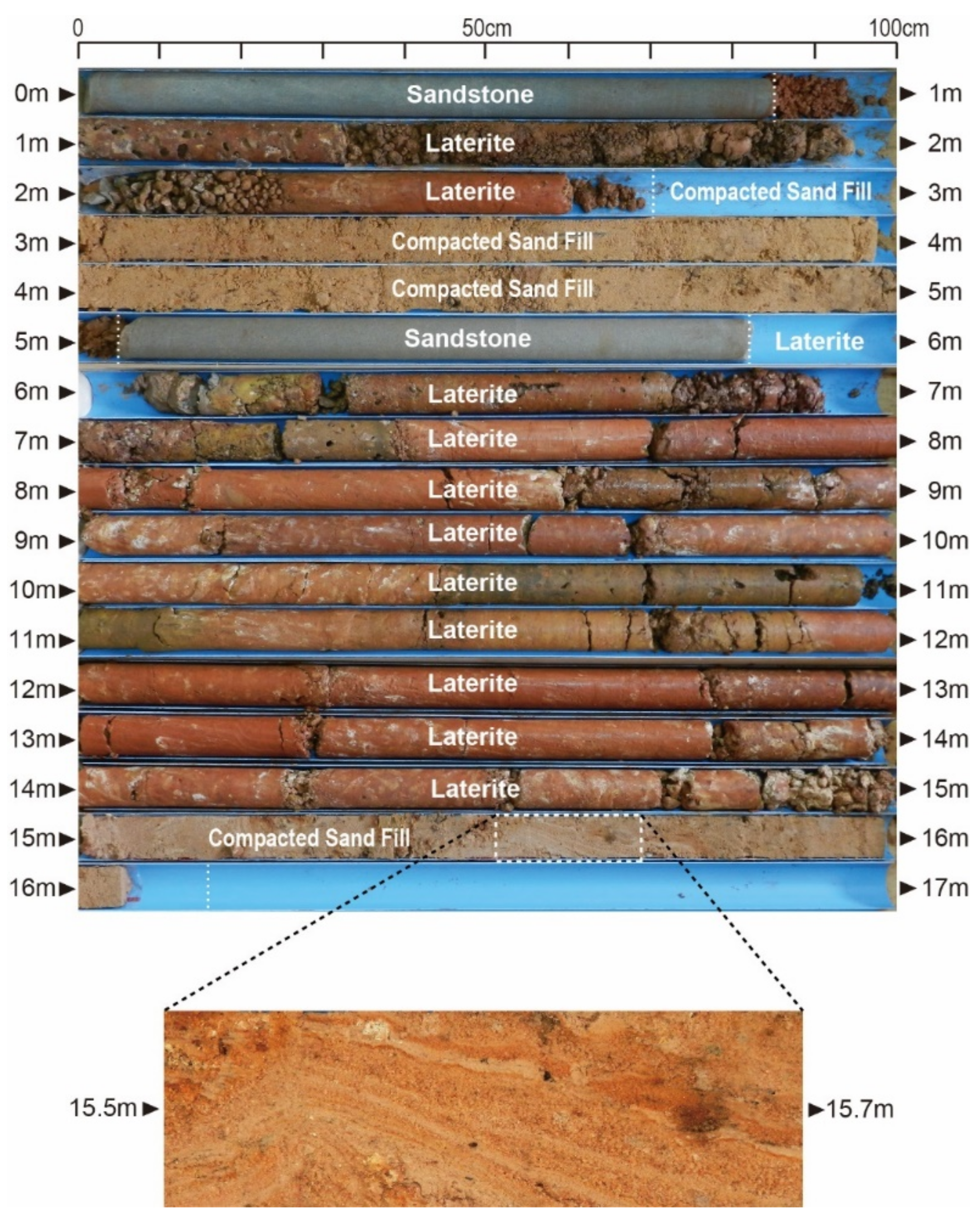
In the horizontal boring from the south wall toward the north side (BYHS–2012), the retaining wall consisted of a single block of sandstone 0.85 m thick (
Figure 8). Behind the sandstone, layers of laterite blocks and laterite chips were confirmed over a thickness of 1.75 m. Further inside, compacted soil continued on to a thickness of 2.48 m. At a depth of 5.08 m, sandstone blocks appeared again over a thickness of 0.77 m, followed by a layer of laterite blocks over a thickness of 9.15 m. At a depth of 15 m, the boring reached sandy compacted soil.
Figure 9 shows a record of cores sampled from BYHS–2012. It is worthy of mention that the compacted soil at a depth of 15.5–15.7 m displayed a laminate structure. Horizontal stratification that appears as a result of compacting, in which sand is laterally sprinkled and tamped down, has also been confirmed in the past during the dismantlement of the northern and southern Libraries, but it is difficult to imagine that the banded structure seen in the photo was made by the compacting method. Rather, it is thought that the banded structure was formed by a chemical weathering effect caused by the flow of seeping water inside the platform earth fill after the platform was constructed. Indeed, traces of chemical weathering, such as seeping, leaching, and sedimentation, were found inside the earth fill.
4.4. Result of a Monitoring of Groundwater Level
A water gauge was attached inside the hole that was made by the vertical boring test (BYV–2010) conducted on the central terrace, and water levels were measured from November 2010 to December 2011. The water pressure gauge that was used is a type that measures absolute water pressure and is susceptible to the influence of atmospheric pressure, so an atmospheric pressure sensor was installed to correct the measurement results. During this time, there was a period when groundwater level monitoring was suspended for three months, from April to July 2011.
Figure 10 shows changes in groundwater level and amount of rainfall. The rainfall data were obtained from a meteorological observation device installed in Angkor Wat during the same period [
18].
The region is largely divided into the rainy season, from May to November, and the dry season, from December to April, and groundwater level fluctuates between these two seasons. During the measurement period, groundwater level was the lowest at 21.8 m in February and March and highest at almost 25 m at the end of October, such that there was a roughly 3 m fluctuation over the year.
Figure 4 shows these groundwater levels together with the water content ratio, and indicates that ground-water level fluctuated to a level roughly 1 m above the lower layer of compacted soil. It should also be noted that the groundwater level measured in the past in the vicinity of Bayon Temple fluctuated between altitudes of 18 to 23.5 m over the year [
19], so groundwater level directly beneath the terrace is assumed to fluctuate at a higher level than its surrounding area.
5. Discussion
5.1. Laterite Foundation Structure Inside the Central Terrace
Clues to the structural distribution of laterite and sandstone blocks inside the central terrace were acquired via the excavation inside the central tower and multiple boring tests conducted from the top and sides of the central terrace. Logs of the boring tests are shown together with the north–south section of the central terrace in
Figure 11 and the plan in
Figure 12.
No laterite or sandstone foundation structure was found directly beneath the central group of towers, but a laterite foundation structure is thought to exist on the outskirts of the central group of towers. The laterite foundation was found to be asymmetrical between the north and south sides, with the north side measuring 7 m in width and the south side measuring 9 m. The height of the laterite foundation structure on the south side is estimated at approximately 6 m, judging by the boring logs from BYV–2010 and BHY2–2010. This dimension roughly corresponds to the height of the central terrace.
Ancient architects and structural designers in Angkor were probably aware that compacted soil is better able to support large loads over a long term compared to laterite masonry structures. Laterite undergoes gradual compressive deformation by continuing to bear a load for a long period of time, but tightly compacted soil can escape deformation, because lateral constraints can prevent its outflow, and because it can maintain a high degree of strength over a long time if kept in a dry condition. The survey that was recently conducted fell short of illustrating the overall picture of the laterite structure inside the central terrace, but it is assumed to be a thick retaining structure with a circular, 20 m-diameter space in the center, to constrain the compacted soil directly beneath the central group of towers from all directions. Additionally, because laterite is highly permeable, rainwater that seeps in from the top of the terrace can swiftly drain toward the bottom and reduce the seepage of water to the compacted soil directly beneath the central group of towers. It is believed that such a support structure was adopted based on a proper awareness of the characteristics of the materials used.
Aside from Bayon, there have been no comprehensive surveys of foundation structures inside the platform of pyramid-shaped temples of the Angkor monuments. However, no obvious evidence of stone support structure has been confirmed beneath the other temples, including the N1 Tower of Prasat Suor Prat, the foundation of which was fully dismantled and reconstructed by JASA [
21], and other pyramid-shaped temples such as Baphuon and Takeo, which have had restoration work completed by international teams. Based on these previous understandings of the other structures of Angkor monuments, there is the possibility that the earthen foundation structure for supporting the massive upper structure had been widely typical throughout the long history of the classical Khmer construction technique.
5.2. Process of Extension of the Central Terrace
Several previous studies were discussed regarding the extension and renovation process of this complexed structure, Bayon [
8,
22,
23,
24,
25,
26]. The result of this survey gave us an additional interpretation on the early stage of extension of the central terrace and its upper towers. As a result of the horizontal boring tests, a 20 cm-thick sandstone block was found on the north side of the laterite structure inside the central terrace, and a 77 cm-thick sandstone block on the south side (
Figure 8). The one on the north side was thin, but it was definitely a processed sandstone block and not gravel.
Cunin noted the possibility that the terrace was extended on two occasions, based on the size and paving method of the floor stones on the terrace and on an observation of the masonry of the retaining wall on the side of the terrace (
Figure 12) [
20]. Additionally, according to a study based on changes in the magnetic susceptibility of sandstone conducted by Uchida and a study based on an analysis of stone masonries by Cunin, the 14th tower, 17th tower, and part of the 12th tower on the central terrace are thought to have been added in later years [
27].
In these ways, the central terrace and the towers on it underwent a complex process of construction, so the laterite structure that was found inside the terrace may have been the terrace of earlier stage, and the sandstone blocks that were used on the outside of the laterite structure may have been detected by these boring surveys. Two towers, the 18th and 20th towers on the terrace, were considered to have been constructed at around the same time as the central group of towers up until now, but the dimension of the inner terrace estimated from the boring tests could not have supported these towers. Thus, the two towers may have been constructed after the central group of towers, which stand on the terrace of an earlier stage. It appears that construction of the central terrace and upper structures underwent a more complex process than has been presumed to date.
5.3. Concern about the Weakening of the Compacted Soil beneath the Central Group of Towers
In the series of archaeological and geotechnical surveys, the current bearing capacity of the compacted soil directly beneath the group of central towers that escaped disturbance by the previous excavations remained uncertain, because no bearing capacity test was carried out. However, as the bearing capacity of the compacted soil below the laterite structure was acquired at BYV-2010, the compacted soil directly beneath the group of central towers is assumed to have a similar level of strength. The bearing capacity of the compacted soil beneath the inner laterite structure consistently had an N-value above 75, which largely surpassed the value of general sandy foundation at the structures in the Angkor monument [
28,
29]. The N-value was largest near an altitude of 25 m, and reached as much as 250 (SPT N-value).
Groundwater level was confirmed as fluctuating at altitudes between 22 m and 25 m throughout the year, but the largest N-value was recorded above the highest groundwater level. Therefore, it was thought that the compacted soil maintained its high bearing capacity by not becoming immersed in groundwater.
In the boring test conducted in the central tower (BYC-2009), the natural sedimentary soil was reached at an altitude of 21–22 m. Above it would be backfill soil from a survey conducted in the 1930s, which had extremely low bearing capacity with an N-value below 5. Judging by the sectional diagram from a record of a survey by EFEO, the excavated area was limited within a diameter of 1.5 m or so below an altitude of 28 m. However, in the diagonal boring from the top of the terrace (BY30-2010), extremely loose dirt and sand were collected from within approximately 2.7 m in the horizontal distance directly beneath the central tower. This low-strength soil area would correspond to the disturbed vertical hole by the past looting before the archaeological excavation survey in 1930s.
Compacted soil can maintain its strength if it is strongly constrained and maintained in a dry condition, but the constraint may have weakened due to the backfill soil and past disturbance by looting. Although the BY30-2010 borehole could confirmed the loose area of the backfill soil at an altitude of 26–27 m, which was higher than the highest annual fluctuation level of ground water, it is possible that the compacted soil under the groundwater level might be a more serious situation.
6. Conclusions
The series of surveys discussed herein were conducted with the objective of clarifying the structure inside the platform of the central terrace that supports the central group of towers at Bayon, and of assessing its structural stability. The inside of the central terrace directly beneath the central group of towers was filled with compacted soil to a thickness of 15.5 m down to the natural sedimentary soil, and no laterite or sandstone supporting structure was confirmed. However, a 6 m-high laterite masonry structure was confirmed on the outside of the area inside the central terrace, directly beneath the central group of towers. Compacted soil continued on beneath the laterite foundation structure down to the natural sedimentary soil. This compacted soil had extremely high bearing capacity with an N-value over 75 and a maximum N-value of 250 according to a standard penetration test. The bearing capacity of the compacted soil directly beneath the central tower that remained undisturbed in any past looting incident was not analyzed, but it is presumed to have a similar high bearing capacity.
Sandstone blocks were found that presumably composed the outer side of the laterite structure inside the central terrace and that had probably enclosed the terrace structure of a prior stage. Extensions of the central terrace and the buildings on it have been noted in past studies, but the process may have been more complex than previously supposed. Only limited information has been acquired about the shape and scope of the laterite structure inside the terrace via the recent boring tests, so the entire picture has yet to be revealed, and further tests are sought hereafter.
The soil that was backfilled after the looting and an archaeological excavation survey inside the Central Tower in the 1930s was found to be loose. No retaining laterite or sandstone wall structure was found beneath the central tower, and the sound compacted soil beneath the central group of towers was not constrained in any way on the side of the disturbed soil. As the groundwater level inside the central terrace was found to fluctuate at an altitude of 22–25 m, the sound compacted soil may have weakened due to water seeping into the unrestrained disturbed soil. Consideration needs to be given to consolidating the disturbed soil or installing a reinforcing measure to support the sound compacted soil from the inside.
Bayon Temple is an important historical heritage in Cambodia today. The central group of towers, in particular, is a symbolic presence that requires sufficient studies and measures to preserve its present state. No distinct deformation or behavior of the central group of towers has been identified through monitoring and simulation analysis to date. However, if the weakening of the compacted soil of the foundation structure advances as a result of a rise in groundwater level caused by concentrated rainfall or changing the water management system in the archaeological park of Angkor, there is the unacceptable risk of the deformation of the terrace. Furthermore, the deformation of the supporting structure might lead to severe damage to the upper structure.
Based on the results of these studies, further investigations are required for developing the appropriate measures to maintain the safety of the central group of towers. It is significant to observe long-term changes of the groundwater level below the terrace to estimate water contents of the compacted soil in each depth. It is also important to monitor the change of water content of the higher level of compacted soil due to rainwater infiltration through the stone joints of the upper surface of the elevated terrace. These clarifications will make it possible to evaluate the degree and extent of weakening and risk of the compacted soil in more detail. In addition, it is necessary to evaluate the static stress on the central terrace caused by the load of the central group of towers, as well as the dynamic stresses, such as wind pressure to the towers, deformation of the superstructure by partial collapse of stone elements, visitor behavior, and so on. The evaluation of these multiple stresses is essential to clarify the threshold value of the minimum capacity bearing for maintaining the sound compacted soil around the weakened fill soil in the vertical excavated shaft. Besides, this evaluation is needed to verify the required bearing capacity and the strengthening method to guarantee the safety of the central group of towers. Based on the fundamental results in this paper, above-mentioned advanced surveys are expected in the future.
Funding
This research was supported financially in part by a Grant-in-Aid for Scientific Research from the Japan Society for the Promotion of Science (Projects No. 25303022 (M. Araya) and 25300004 (T. Haraguchi)).
Institutional Review Board Statement
Not applicable.
Informed Consent Statement
Not applicable.
Data Availability Statement
Not applicable.
Acknowledgments
The author would like to thank the companies and individuals who cooperated in the series of geotechnical and archaeological surveys, namely Iwasaki Yoshinori, Fukuda Mitsuharu, Haraguchi Tsuyoshi, Kitamura Atsumi, Ide Yoshiaki, Yamamoto Nobuo, Uchida Etsuo, Tokunaga Tomochika, Mogi Kasturo, Chia Nol, Sour Sothy, Cheam Pross, Kou Vet, Lun Votey, and Robert McCarthy. All research and restoration work for this study was directed by Nakagawa Takeshi, Director of the Japanese Government Team for Safeguarding Angkor. I also wish to acknowledge the continuing support and collaboration of APSARA National Authority, Cambodia.
Conflicts of Interest
The author declares no conflict of interest. The funders had no role in the design of the study; in the collection, analyses, or interpretation of data; in the writing of the manuscript; or in the decision to publish the results.
References
- Iwasaki, Y.; Yamamoto, I.; Araya, M. Stabilization of the Central Tower and Countermeasures for Long Term. In The Master Plan for the Conservation and Restoration of the Bayon Complex; Japanese Government Team for Safeguarding Angkor, Ed.; Japan International Cooperation Center: Tokyo, Japan, 2005; pp. 206–222. [Google Scholar]
- Maeda, T.; Sugiura, Y. Bayon Temple Micro-Tremor Measurement Survey. In The Master Plan for the Conservation and Restoration of the Bayon Complex; Japanese Government Team for Safeguarding Angkor, Ed.; Japan International Cooperation Center: Tokyo, Japan, 2005; pp. 464–510. [Google Scholar]
- Maeda, T.; Sugiura, Y.; Hirai, T. FEM modeling of the towers in Bayon temple in Cambodia based on micro-tremor measurements. Adv. Eng. Softw. 2008, 39, 346–355. [Google Scholar] [CrossRef]
- Yamada, S.; Araya, M.; Fukuda, M.; Iwasaki, Y. Statistical time series analysis of crack movements at Bayon main tower, Cambodia. Adv. Mater. Res. 2010, 133–134, 397–402. [Google Scholar] [CrossRef]
- Hashimoto, R.; Koyama, T.; Kikumoto, M.; Saito, T.; Mimura, M. Stability Analysis of masonry structure in Angkor Ruin considering the construction quality of the foundation. J. Civ. Eng. Res. 2014, 4, 78–82. [Google Scholar]
- Hayashi, M.; Yamada, S.; Araya, M.; Koyama, T.; Iwasaki, Y. Study for Reinforcement Planning of Masonry Structure with Cracks at Bayon Main Tower, Angkor. In Advances in Discontinuous Numerical Methods and Applications in Geomechanics and Geoengineering; Zhao, J., Ohnishi, Y., Zhao, G.F., Sasaki, T., Eds.; Taylor & Francis Group: London, UK, 2012; pp. 247–252. [Google Scholar]
- Ohnishi, Y.; Sasaki, T.; Koyama, T.; Hagiwara, T.; Miki, S.; Shimauchi, T. Recent insights into analytical precision and modelling of DDA and NMM for practical problems. Geomech. Geoengin. 2014, 9, 97–112. [Google Scholar] [CrossRef]
- Dumarçay, J. Histoire architectural du temple. In Le Bayon; Archéologiques de l’EFEO: Paris, France, 1973; pp. 3–64. [Google Scholar]
- Marchal, H.; Trouvé, G. Chronique. Bayon Bull. L’Ecole Française D’Extreme-Orient 1933, 33, 1116–1117. [Google Scholar]
- Trouvé, G. Août 1933, Rapport de la Conservation d’Angkor. In l’École Française d’Extrême-Orient Archives; unpublished.
- Polkinghorne, M.; Pottier, C.; Fischer, C. One buddha can hide another. J. Asiat. 2013, 301, 575–624. [Google Scholar]
- Trouvé, G. 16 Août 1933, Journal de Fouilles de la Conservation d’Angkor, 10. In l’École Française d’Extrême-Orient Archives; unpublished.
- Marchal, H. Chronique. Sondages au Bayon. Bull. l’Ecole Française d’Extreme-Orient 1937, 37, 637–651. [Google Scholar]
- Sugimoto, Y.; Yamada, N.; Tokunaga, T.; Metwaly, M.; Mogi, K.; Onishi, K.; Shimoda, I.; Iwasaki, Y. Electrical resistivity survey in Bayon temple, Angkor. In Proceeding of the Society of Exploration Geophysicists of Japan Conference, Tokyo, Japan, 13–15 May 2008; Volume 118, pp. 288–291. [Google Scholar]
- Onishi, K.; Tokunaga, T.; Sugimoto, Y.; Yamada, N.; Metwaly, M.; Mogi, K.; Shimoda, I.; Iwasaki, Y. Identifying damaged areas inside a masonry monument using a combined interpretation of resistivity and ground-penetrating radar data. Explor. Geophys. 2014, 45, 177–188. [Google Scholar] [CrossRef]
- Shimoda, I.; Yamamoto, N.; Kou, V.; Lun, V. Archaeological excavation survey at the cambers of Central Tower. In Report on the Conservation Research of the Bayon, Angkor Thom, Kingdom of Cambodia (Book II); Japanese Government Team for Safeguarding Angkor, Ed.; Japan-APSARA Safeguarding Angkor: Tokyo, Japan, 2011; pp. 44–55. [Google Scholar]
- Iwasaki, Y. Geotechnical, Geological and Environmental Investigations. In Report on the Conservation and Restoration Work of the Northern Library of Bayon, Angkor Thom, Kingdom of Cambodia; Japanese Government Team for Safeguarding Angkor, Ed.; Japan International Cooperation Center: Tokyo, Japan, 2000; pp. 95–101. [Google Scholar]
- Waragi, T.; Morishima, W.; Hada, A. Angkor Wat meteorological observation station (AMOS): Installation of monitoring system and preliminary results of observation at Angkor Wat Temple, Cambodia. Proc. Inst. Nat. Sci. Nihon Univ. 2013, 48, 35–48. [Google Scholar]
- Iwasaki, Y. Water Problems in Angkor. In Annual Report on the Technical Survey of Angkor Monument 2003; Japanese Government Team for Safeguarding Angkor, Ed.; Japan International Cooperation Center: Tokyo, Japan, 2003; pp. 225–237. [Google Scholar]
- Cunin, O. De Ta Prohm au Bayon: Analyse Comparative de L’histoire Architecturale des Principaux Monuments du Style du Bayon. Ph.D. Thesis, Institut National Polytechnique de Lorraine, Nancy, France, 2004. [Google Scholar]
- Iwasaki, Y.; Fukuda, M.; Nakagawa, K.; Akazawa, Y.; Shimoda, I.; Nakagawa, T. Geotechnical Aspects of the N1 Tower, Prasat Sour Prat, Angkor Thom, Cambodia. Adv. Mater. Res. 2010, 133–134, 113–118. [Google Scholar] [CrossRef]
- Cunin, O. The Bayon: An archaeological and architectural study. In Bayon: New Perspectives; Clark, J., Ed.; River Books: Bangkok, Thailand, 2007; pp. 136–229. [Google Scholar]
- Nishimoto, S. Notes on the building phases of the face towers on the uppermost terrace at Bayon. In Fourth Symposium on the Bayon, Final Report; UNESCO, Ed.; UNESCO: Paris, France, 2000; pp. 91–97. [Google Scholar]
- Nishimoto, S. The Construction Process of Bayon Temple. Ars Buddhica 2004, 274, 97–110. [Google Scholar]
- Parmentier, H. Modifications subies par le Bayon au cours de son execution: Notes d’archéologie indochinoise VIII. Bull. L’Ecole Française D’Extreme-Orient 1927, 27, 149–165. [Google Scholar] [CrossRef]
- Parmentier, H. Autres modifications subies par le Bayon au cours de son execution: Notes d’archéologie indochinoise IX. Bull. L’ecole Française D’extreme-Orient 1936, 36, 281–286. [Google Scholar] [CrossRef]
- Uchida, E.; Cunin, O.; Shimoda, I.; Suda, C.; Nakagawa, T. The construction process of the Angkor monuments elucidated by the magnetic susceptibility of sandstone. Archaeometry 2003, 45, 221–232. [Google Scholar] [CrossRef]
- Iwasaki, Y.; Fukuda, M.; Shiba, T.; Shimoda, I. Study of Ground near the Northern Library inside the Outermost Enclosure of Angkor Wat. In Annual Report on the Technical Survey of Angkor Monument 2002; Japanese Government Team for Safeguarding Angkor, Ed.; Japan International Cooperation Center: Tokyo, Japan, 2002; pp. 295–304. [Google Scholar]
- Iwasaki, I.; Fukuda, M. Outline of Building Structure, geo-technological Investigation and Theme for Conservation and Restoration. In The Master Plan for the Conservation and Restoration of the Bayon Complex; Japanese Government Team for Safeguarding Angkor, Ed.; Japan International Cooperation Center: Tokyo, Japan, 2005; pp. 36–45. [Google Scholar]
| Publisher’s Note: MDPI stays neutral with regard to jurisdictional claims in published maps and institutional affiliations. |
© 2021 by the author. Licensee MDPI, Basel, Switzerland. This article is an open access article distributed under the terms and conditions of the Creative Commons Attribution (CC BY) license (https://creativecommons.org/licenses/by/4.0/).


