
Multi-Leaf Stone Masonry Walls in Egypt: A Legend


Abstract
:1. Introduction
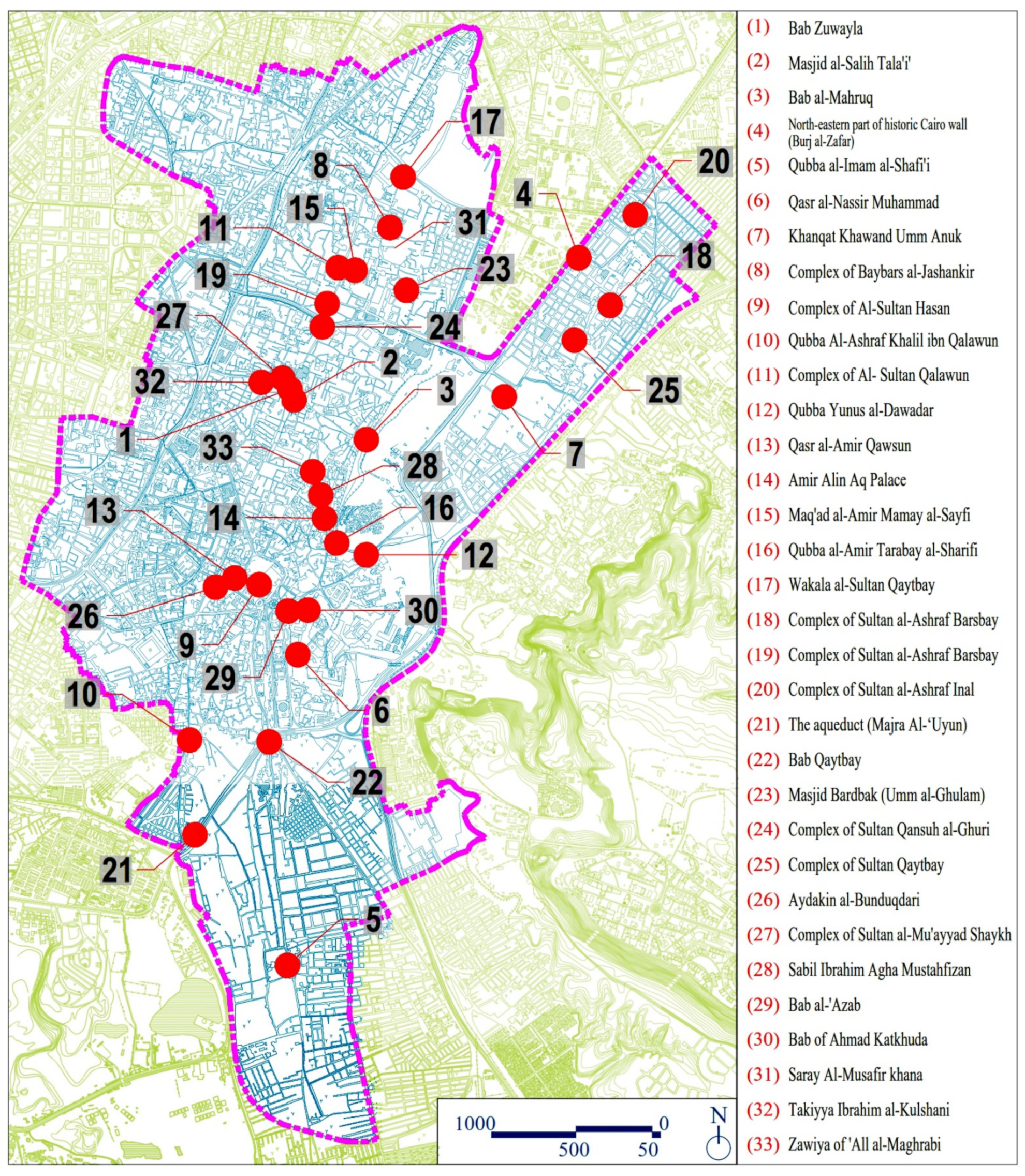
2. Field Survey
2.1. Adopted Methodology
- (i)
- The relative thicknesses of the different layers;
- (ii)
- The ratio between the thicknesses of the inner layers and the total cross-section of the wall;
- (iii)
- The filling materials used to construct the inner core layer;
- (iv)
- The connectivity/constraints types between the inner and external layers;
- (v)
- The construction techniques of the multiple-leaf masonry wall.
2.2. Major Findings
2.2.1. Usage
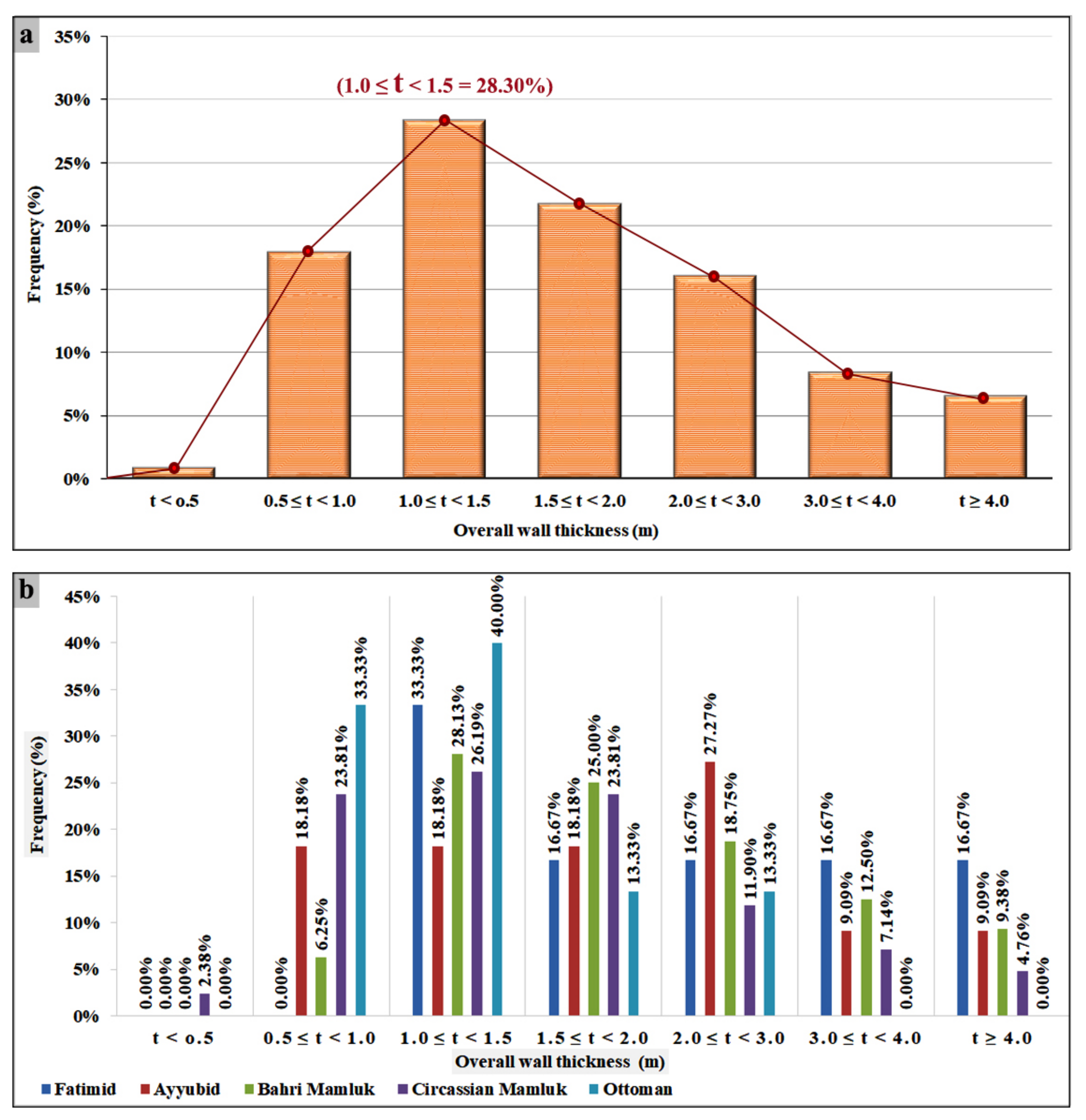
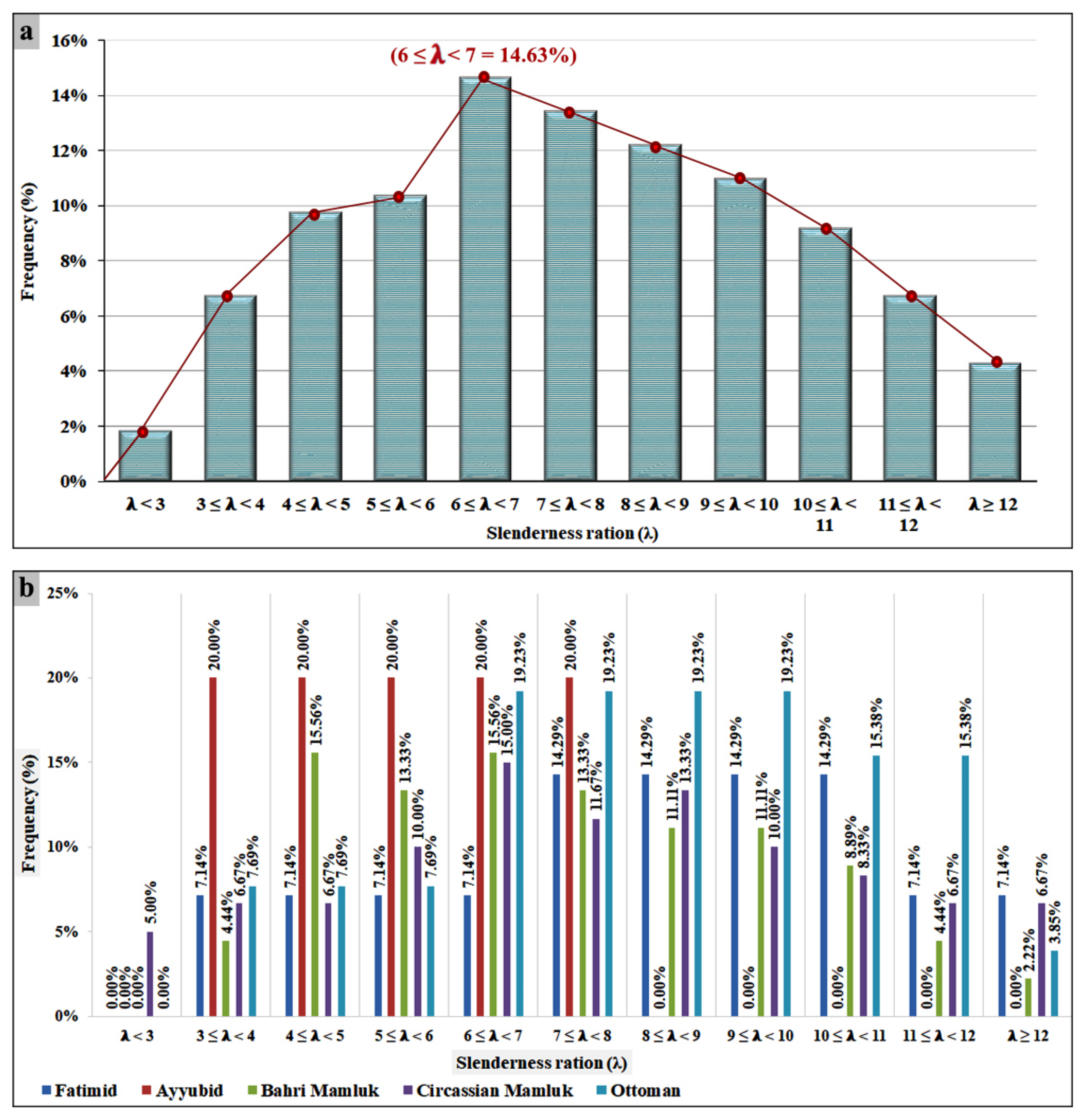
2.2.2. Geometry
2.2.3. Typology
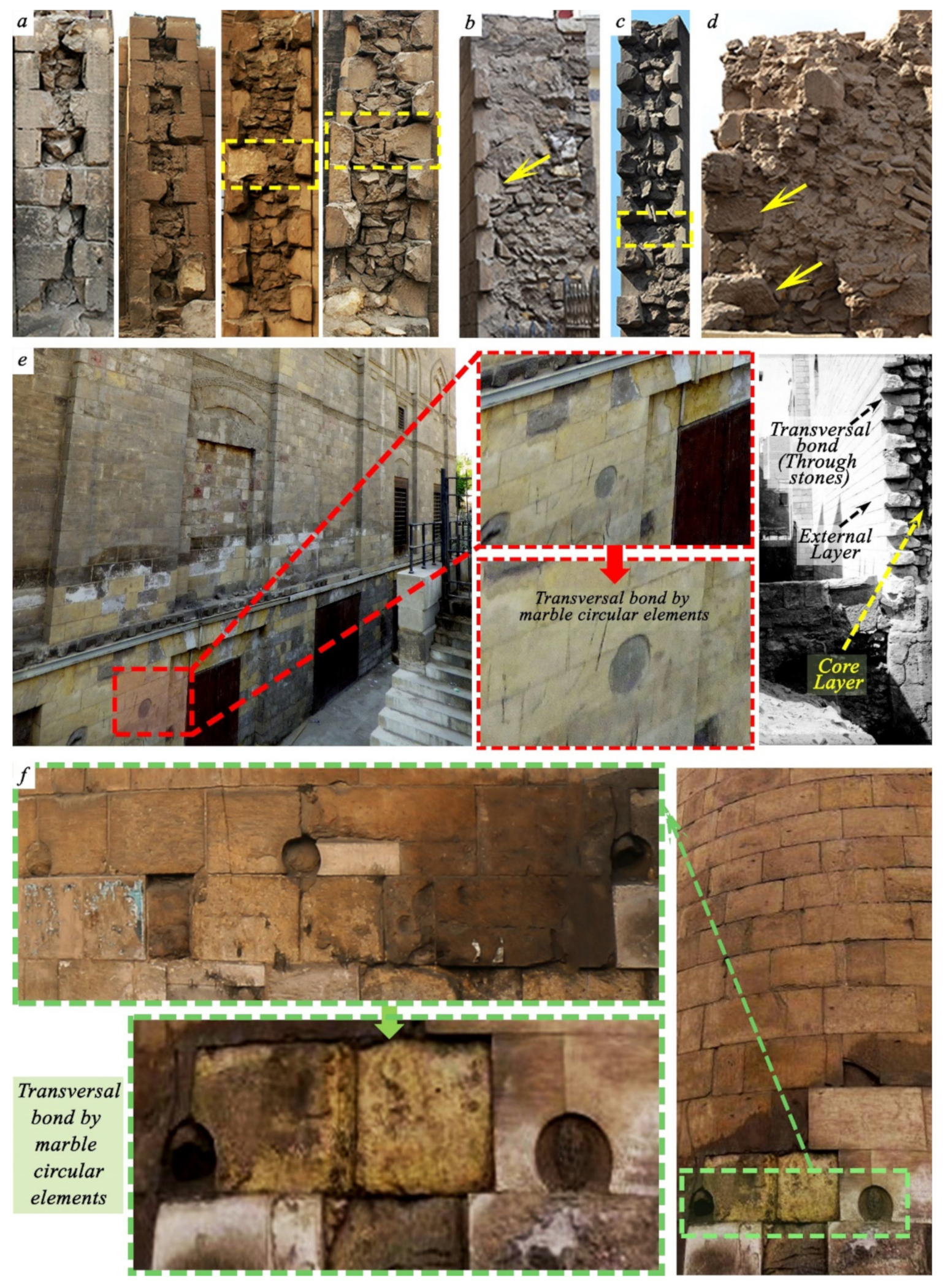
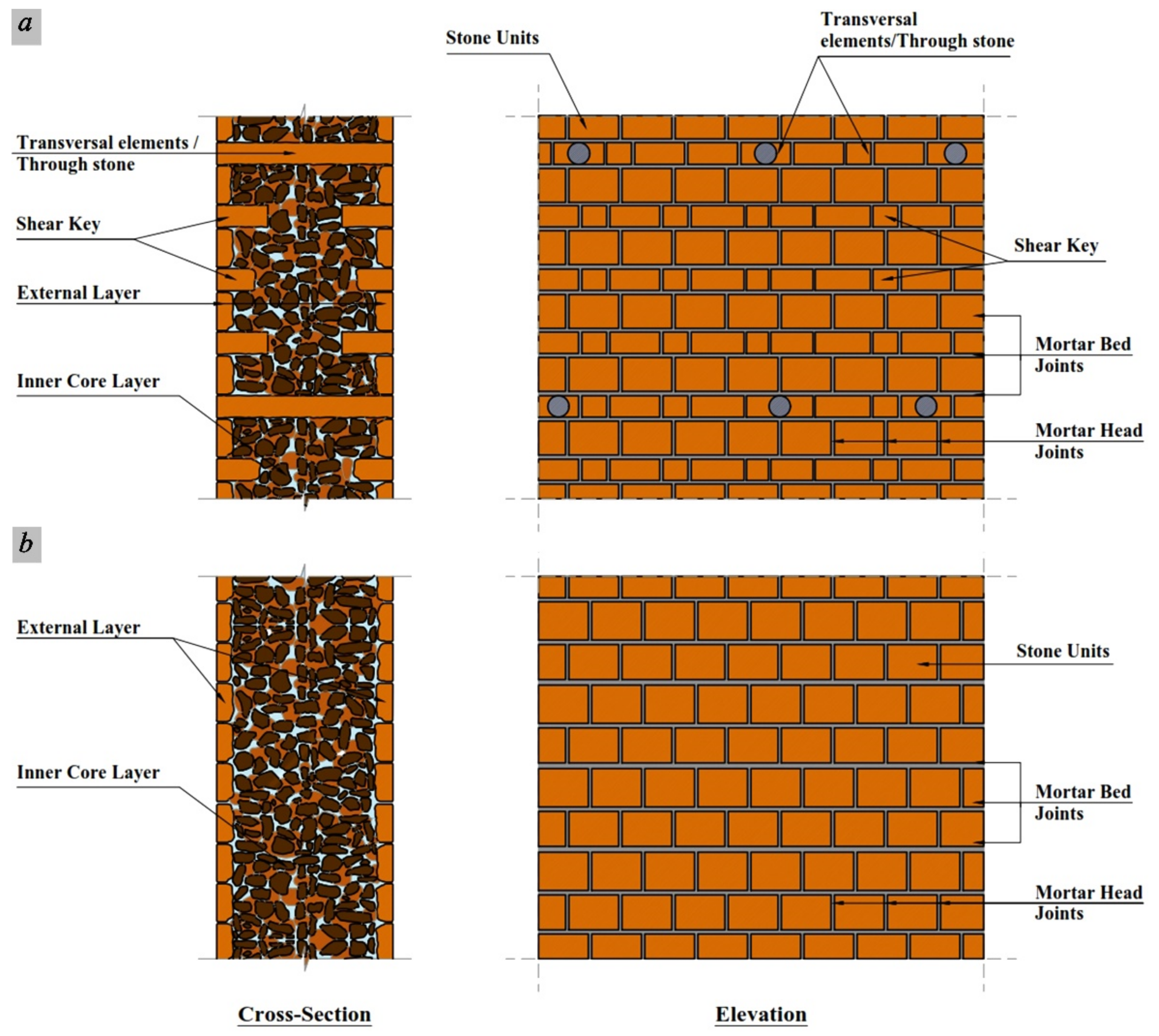
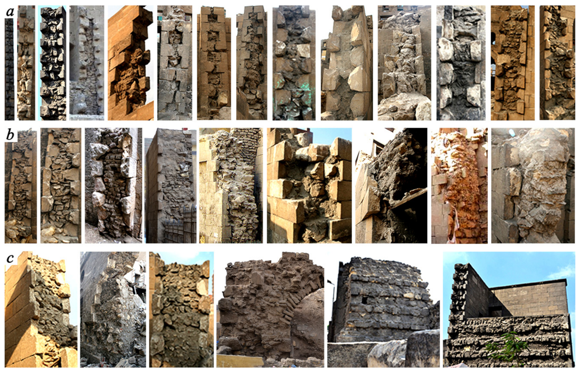
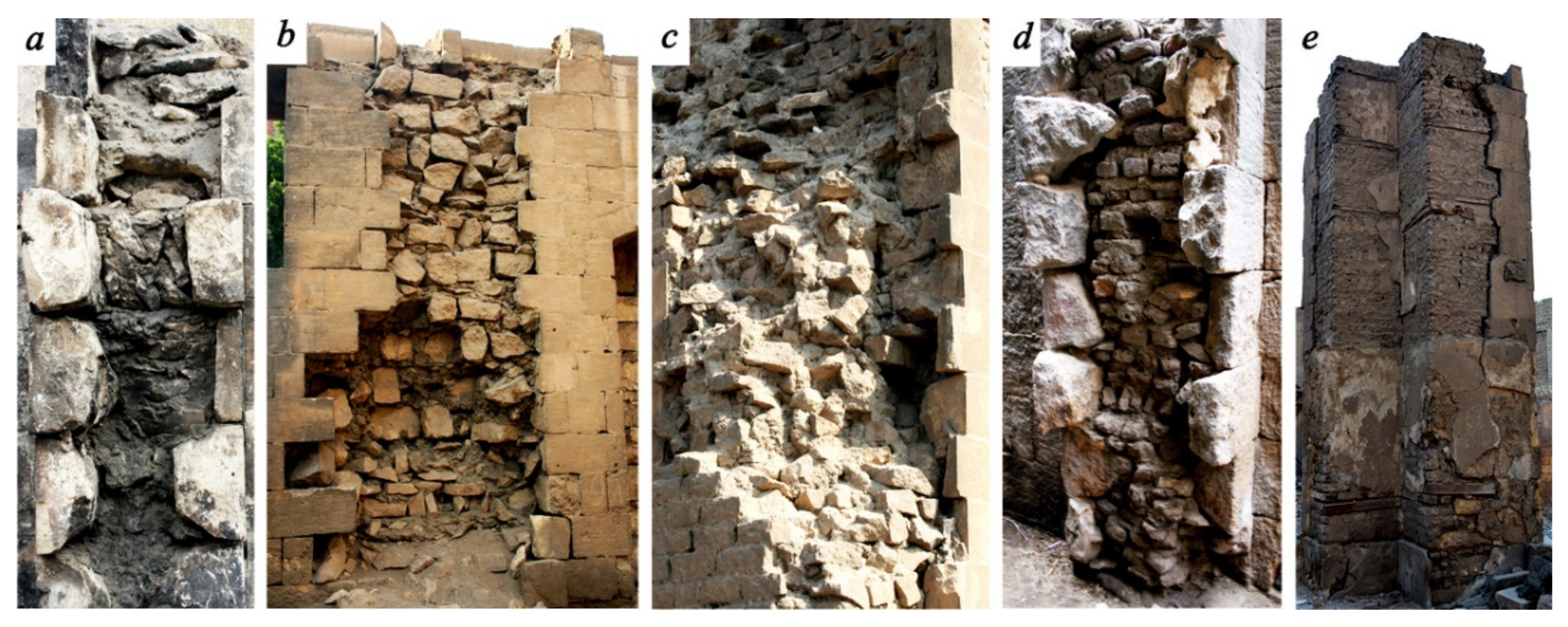
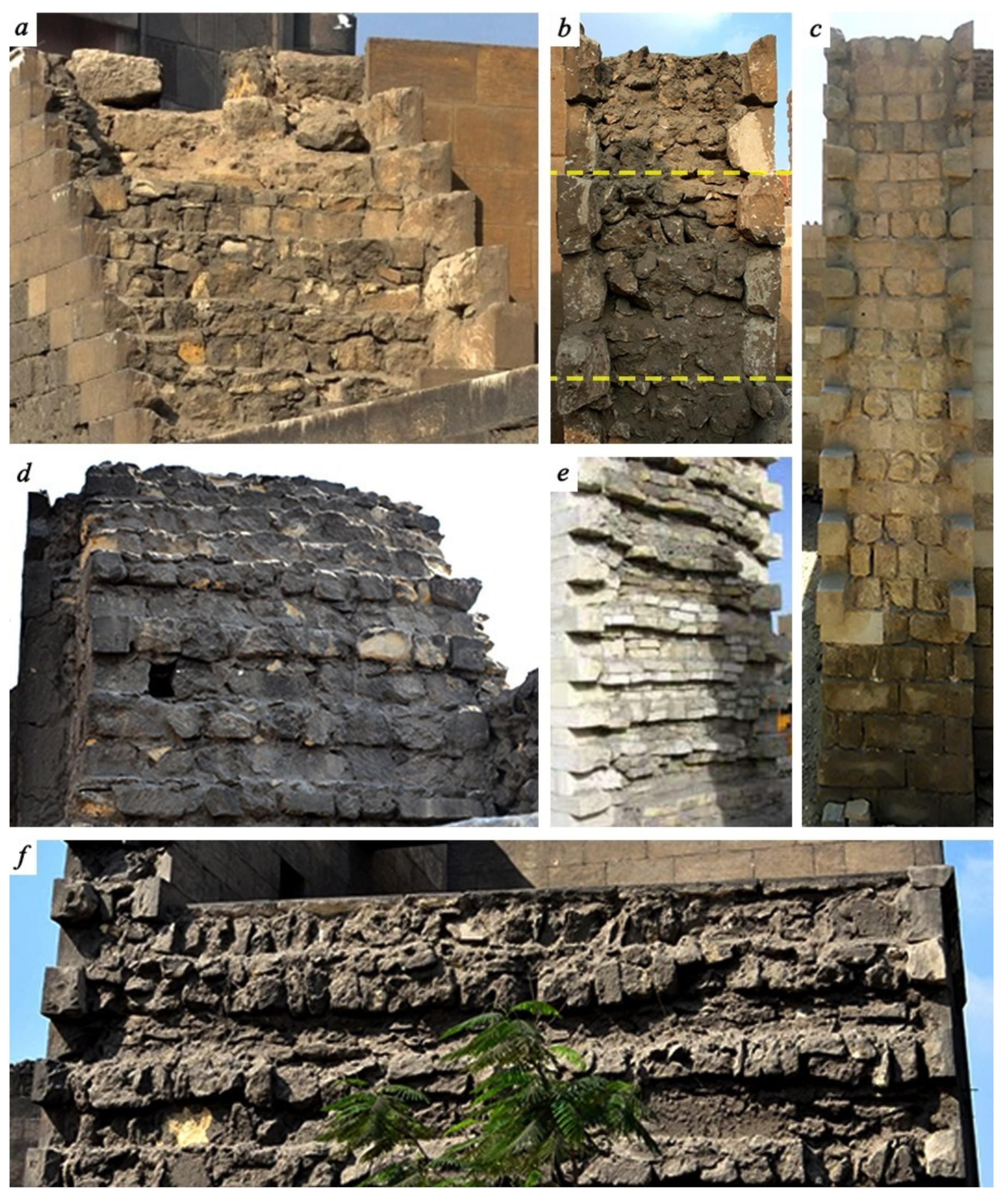
- Walls with straight collar joints, where the inner layer was not interconnected with the outer layer. Usually, the inner layer was constructed with an utterly cohesionless infill held by two separate external leaves, while the outer leaves were made of well-dressed limestone blocks with nearly uniform dimensions, ashlars limestone facing system, bonded in horizontal courses. Only a thin interface layer of mortar was found between the three layers (see Figure 5).
- Walls with keyed collar joints, where the external layer was built with ashlars limestone blocks with variable thickness, creating shear studs to ensure proper connectivity with the inner core infill (see Figure 6a–d).
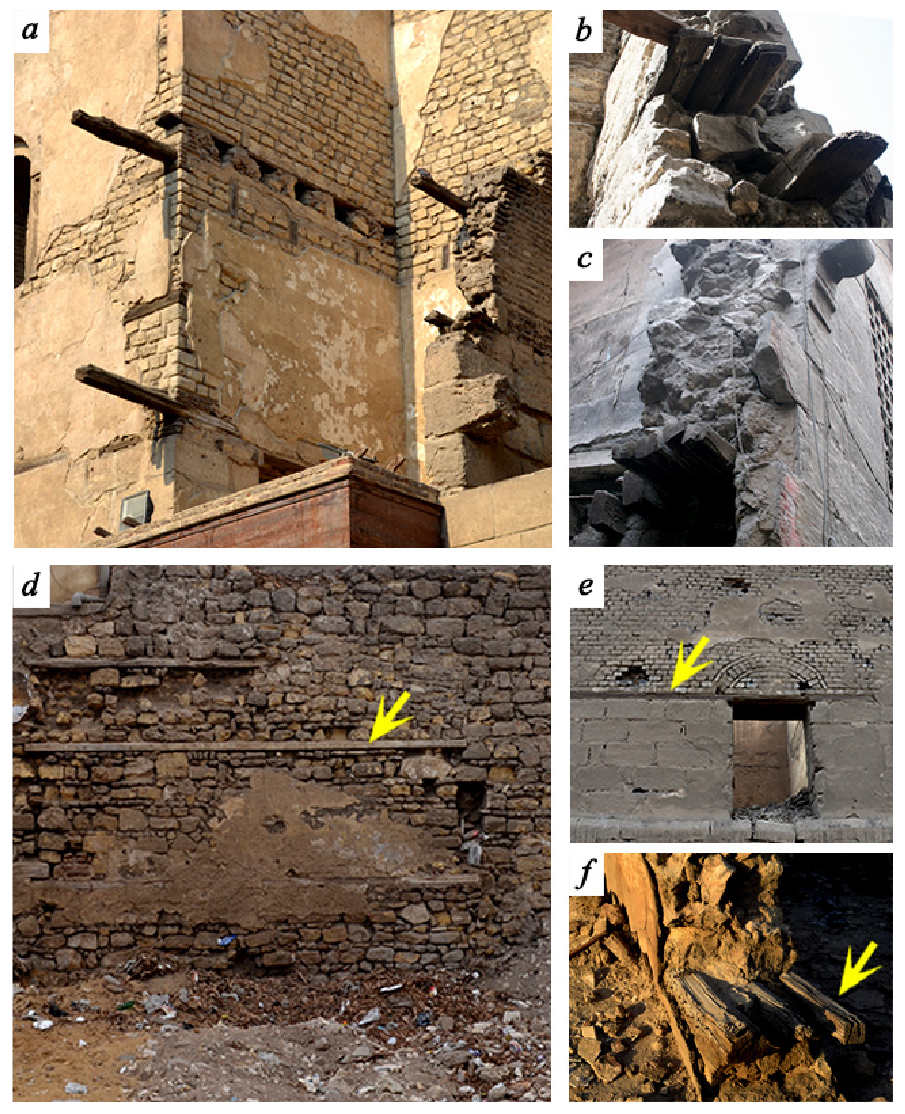
- Walls with the transversal bond or tie elements in the cross-linking of the three layers by the use of either header stones (through stones), timber logs or circular marble elements; this ultimately ensured the composite behavior of the wall and enhanced the global performance with the applied external loads (see Figure 6e,f).
2.2.4. Constituent Materials
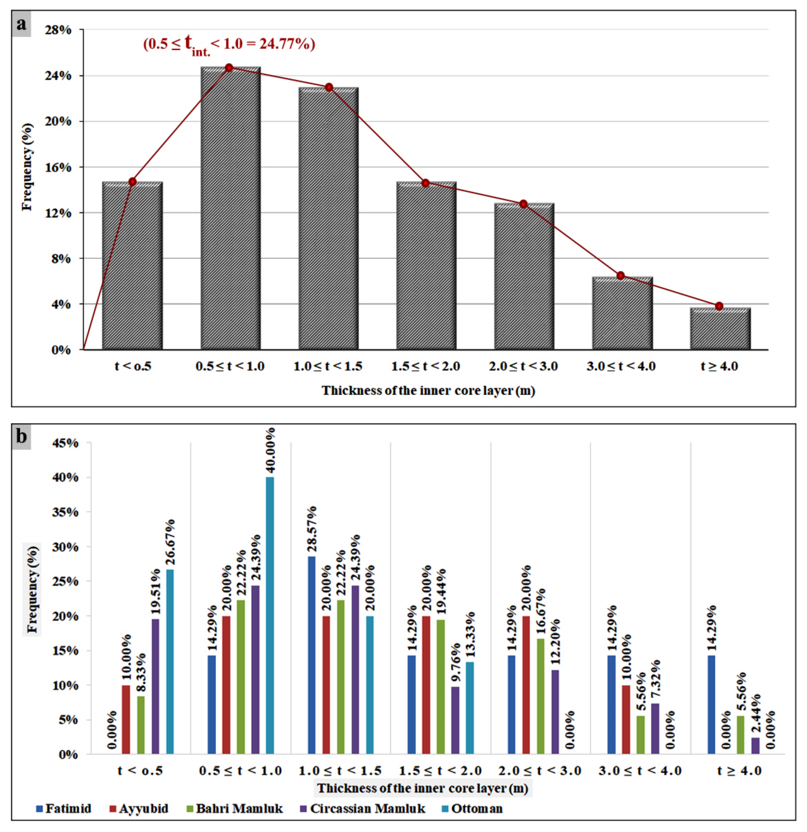
2.2.5. Characterization of the Inner and External Layers
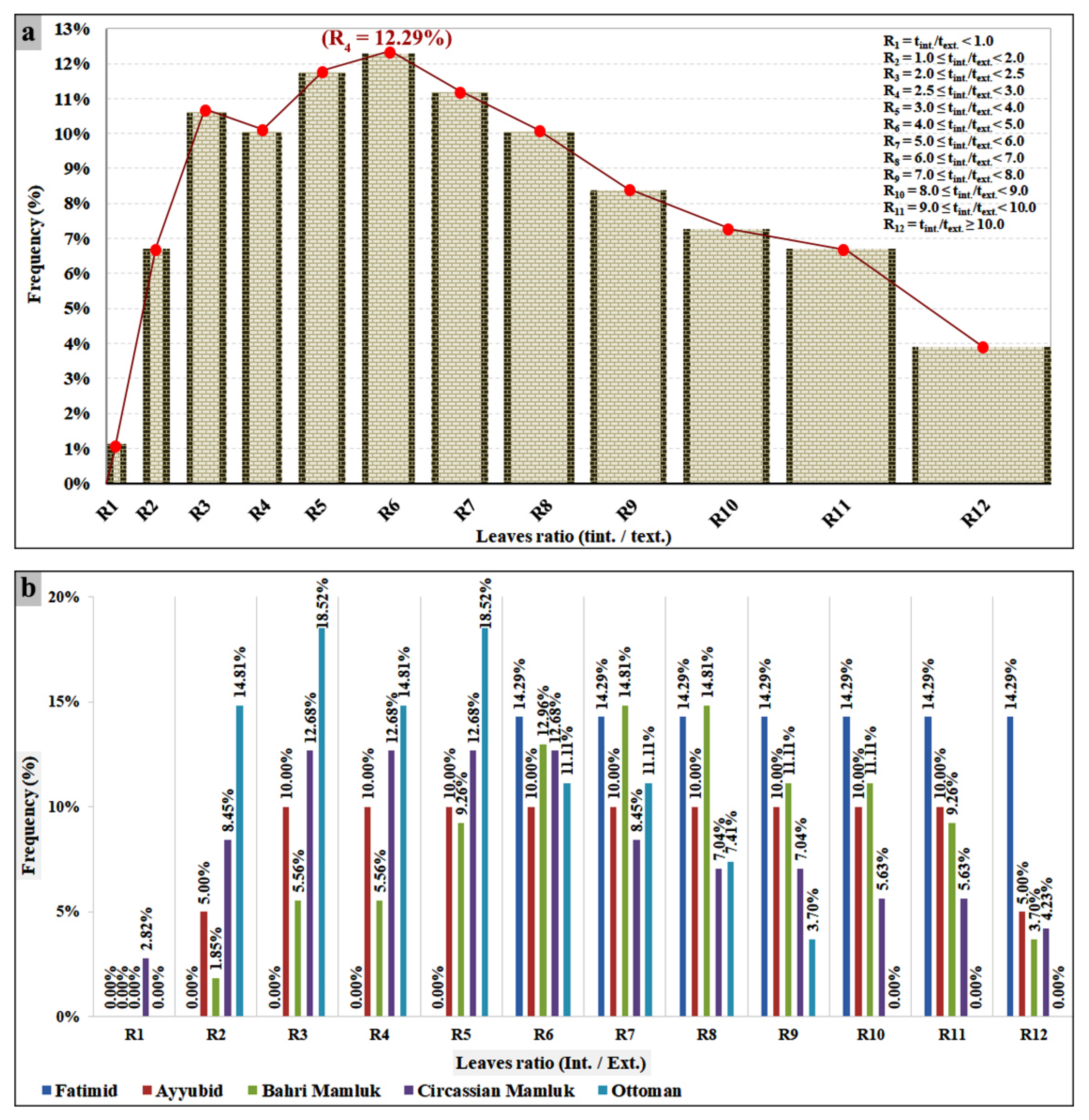
2.2.6. Relative Thickness of the Layers
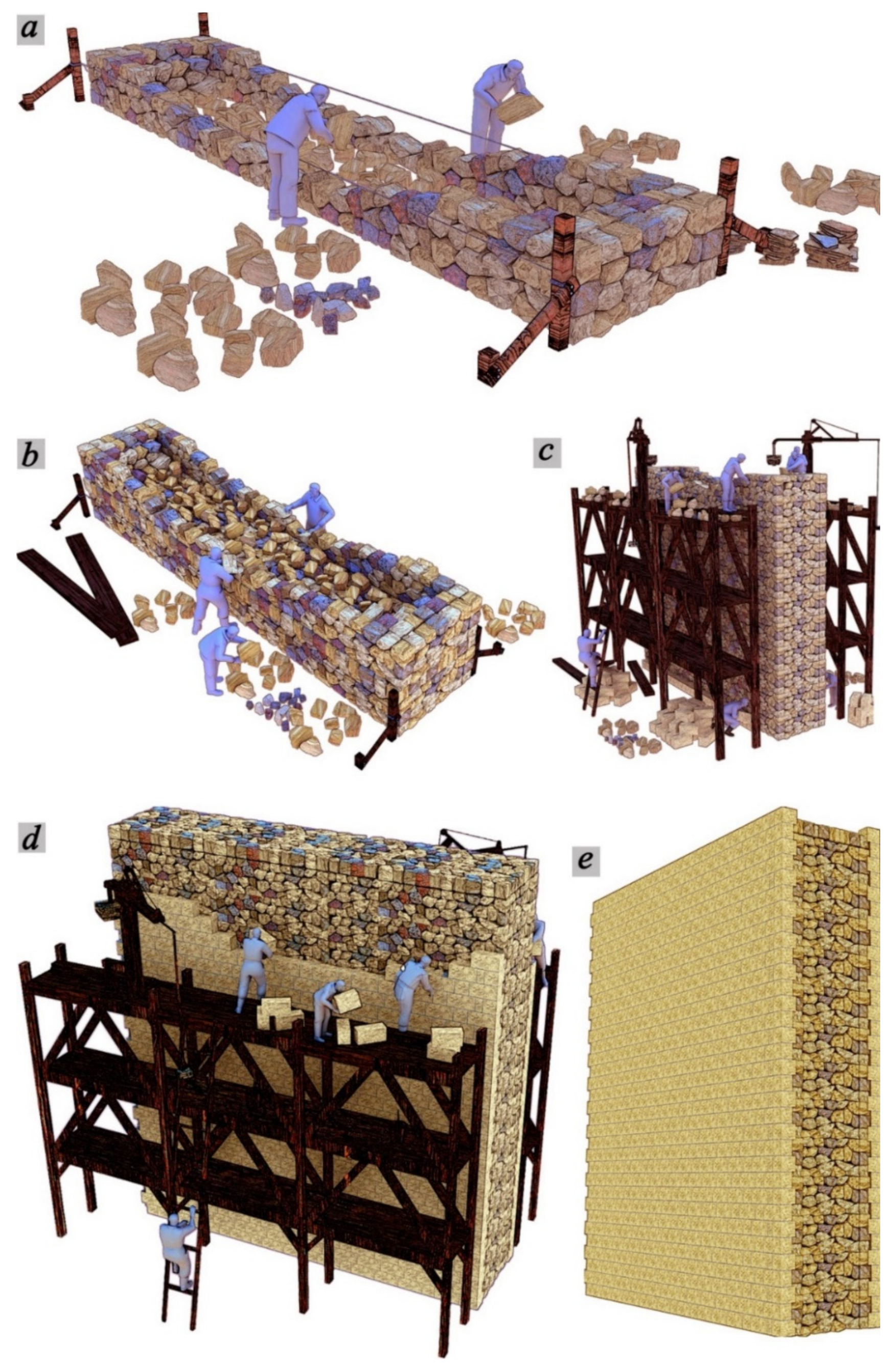
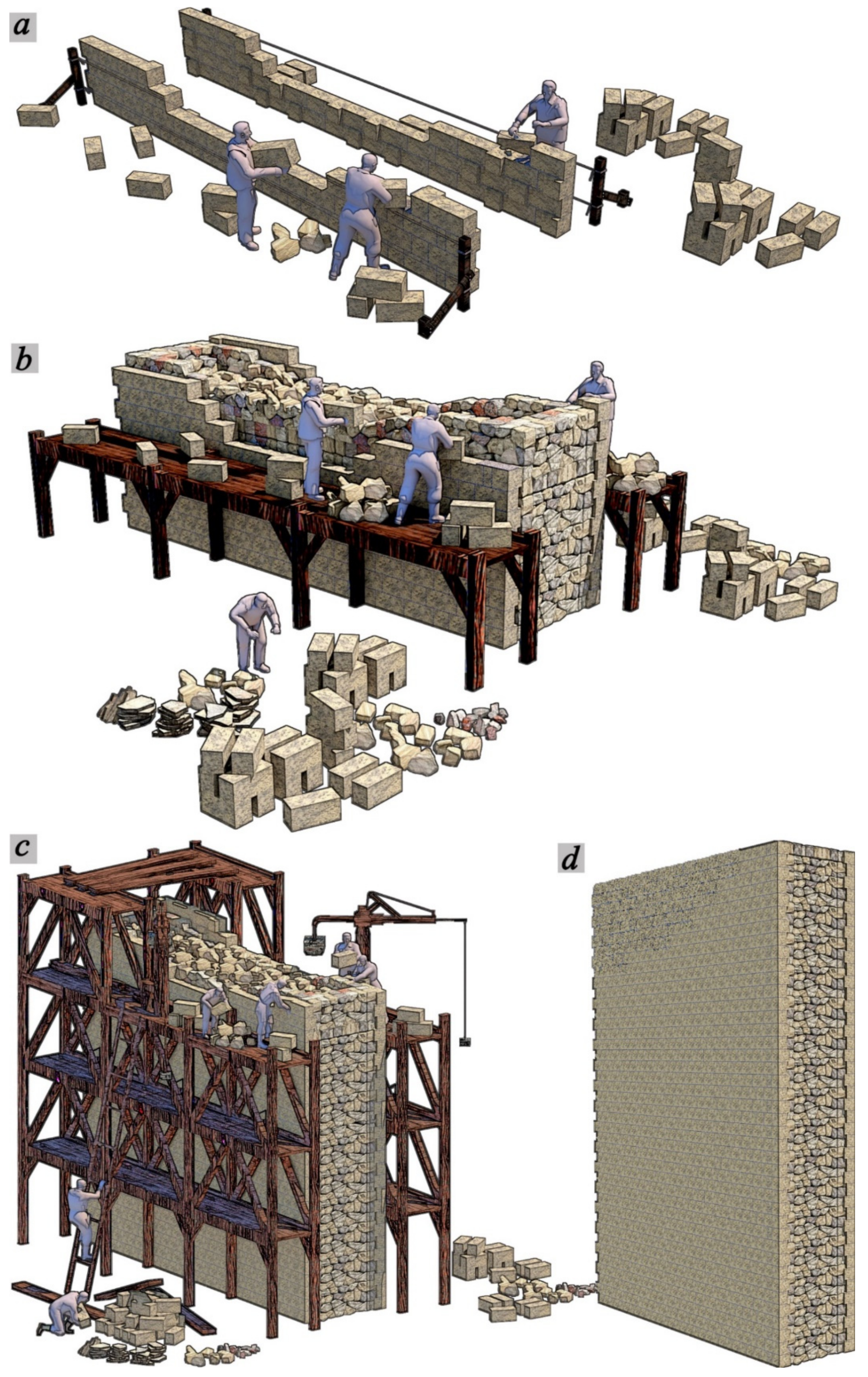
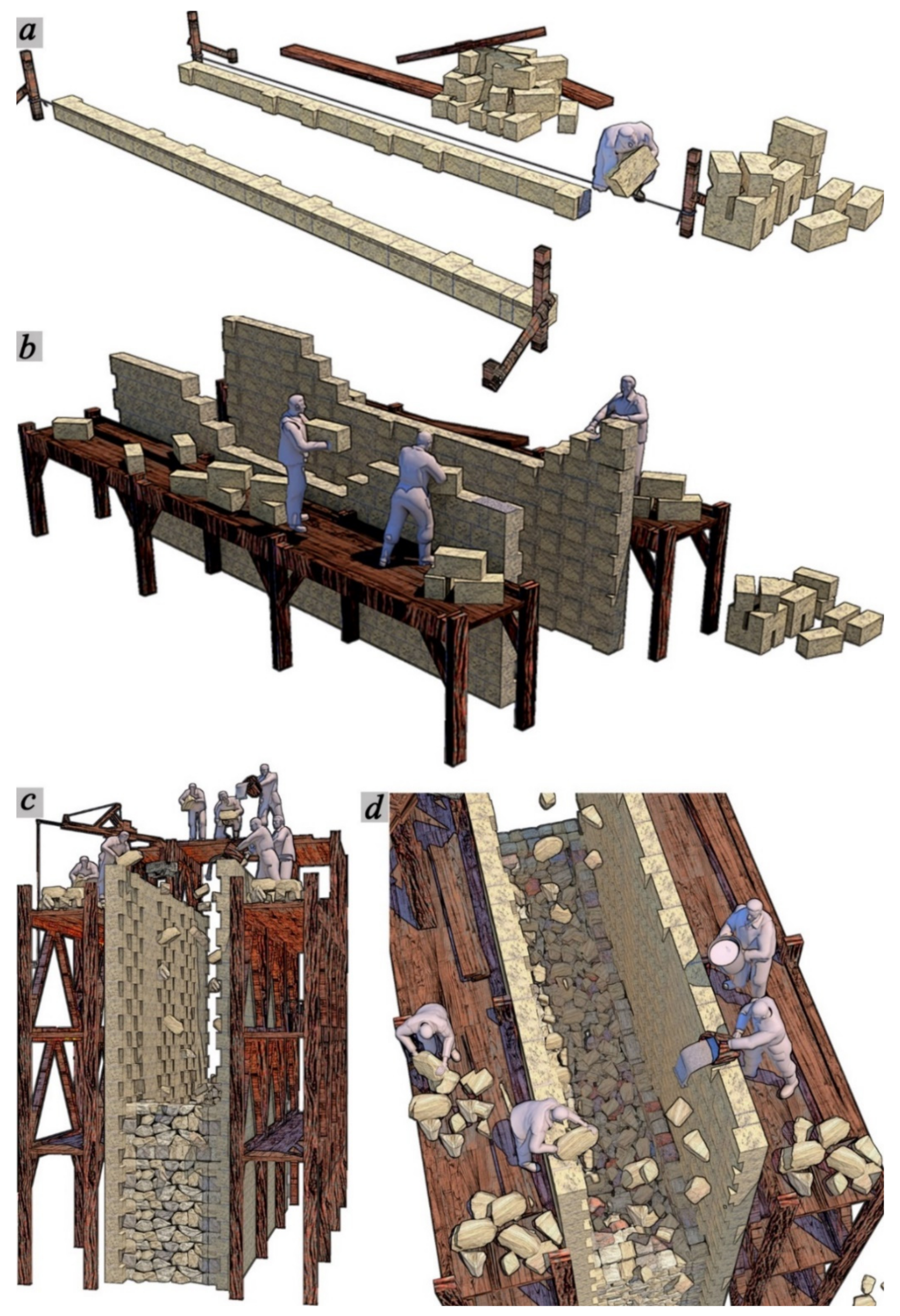
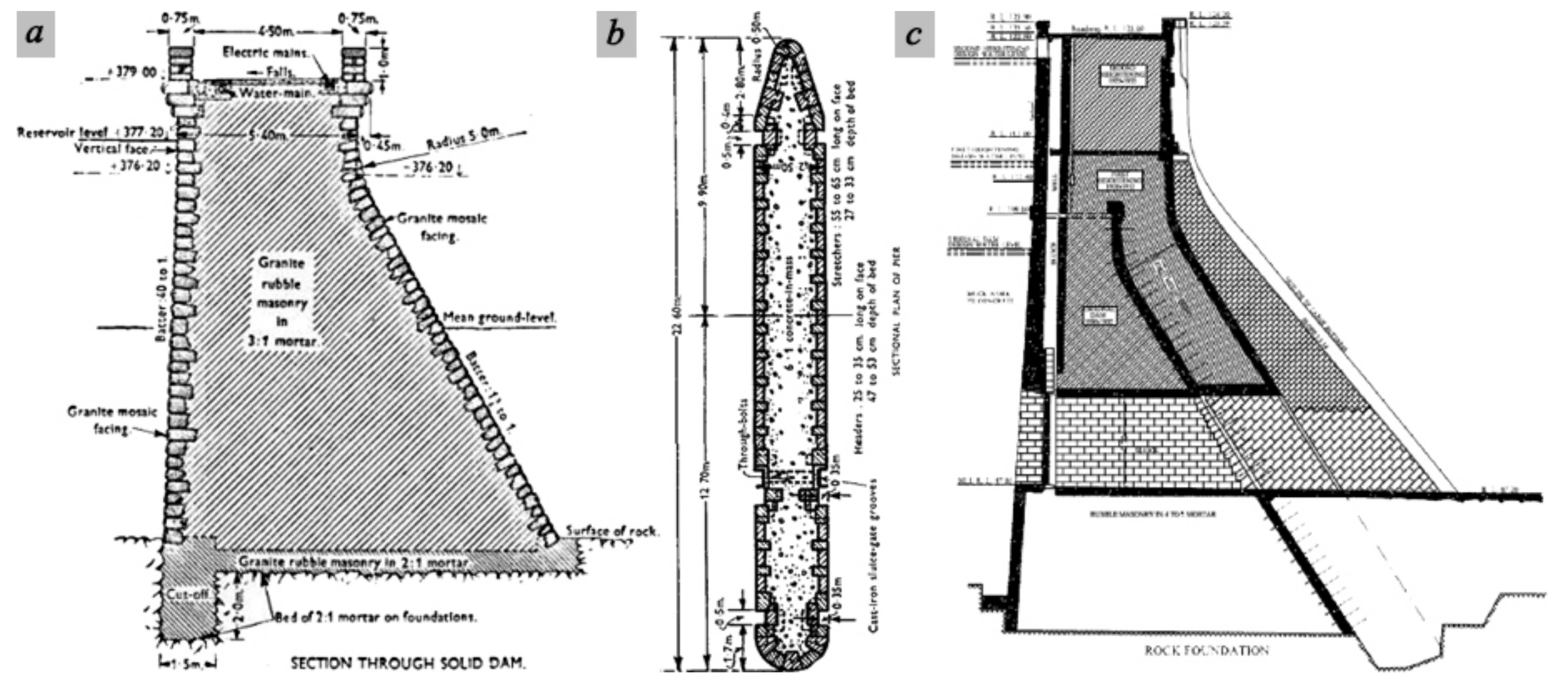
3. Construction Hypotheses of Multiple-Leaf Masonry Walls
3.1. Construction Hypothesis (I): Weak Inner Core
3.2. Construction Hypothesis (II): Monolithic Core Infill
3.3. Construction Hypothesis (III): Thick Core Infill
4. Discussion
5. Conclusions
Author Contributions
Funding
Data Availability Statement
Acknowledgments
Conflicts of Interest
References
- Aldreghetti, I.; Baraldi, D.; Boscato, G.; Cecchi, A.; Massaria, L.; Pavlovic, M.; Reccia, E.; Tofani, I. Multi-Leaf Masonry Walls with Full, Damaged and Consolidated Infill: Experimental and Numerical Analyses. Key Eng. Mater. 2017, 747, 488–495. [Google Scholar] [CrossRef]
- Egermann, R.; Frick, B.; Neuwald, C. Analytical and experimental approach to the load bearing behaviour of multiple leaf masonry. In Structural Repair and Maintenace of Historical Buildings III (STREMA); WIT Press: Southampton, UK; Boston, MA, USA, 1993. [Google Scholar]
- Drysdale, R.G.; Hamid, A.A.; Baker, L.R. Masonry Structures: Behavior and Design; Leon, B.M.D., Zurite, P., Handy, S., Eds.; Prentice Hall: Hoboken, NJ, USA, 1999. [Google Scholar]
- Drei, A.; Fontana, A. Influence of geometrical and material properties on multiple-leaf walls behaviour. WIT Trans. Built Environ. 2001, 55, 2001. [Google Scholar]
- Feilden, B.M. Conservation of Historic Buildings; International Centre for the Study of the Preservation and the Restoration of Cultural Property (ICCROM): Rome, Italy, 2003. [Google Scholar]
- Pulatsu, B.; Bretas, E.M.; Lourenco, P. Discrete element modeling of masonry structures: Validation and application. Earthq. Struct. 2016, 11, 563–582. [Google Scholar] [CrossRef]
- Amer, O.; Aita, D.; Mohamed, E.K.; Torky, A.; Shawky, A. Experimental investigations and microstructural characterization for construction materials of historic multi-leaf stone-Masonry Walls. Heritage 2021, 4, 135. [Google Scholar] [CrossRef]
- Pina-Henriques, J.; Lourenço, P.; Binda, L.; Anzani, A. Testing and modelling of multiple-leaf masonry walls under shear and compression. In Structural Analysis of Historical Constructions; Modena, C., Lourenço, P.B., Roca, P., Eds.; Taylor & Francis Group: London, UK, 2004; pp. 299–310. ISBN 04-1536-379-9. [Google Scholar]
- Pina-Henriques, J.L. Masonry under Compression: Failure Analysis and Long-Term Effects. Ph.D. Thesis, University of Minho, Braga, Portugal, 2005. [Google Scholar]
- Da-Porto, F.; Valluzzi, M.R.; Modena, C. Investigations for the knowledge of multi-Ieaf stone masonry walls. In Proceedings of the First International Congress on Construction History, Madrid, Spain, 20–24 January 2003. [Google Scholar]
- De Felice, G. Out-of-Plane Seismic Capacity of Masonry Depending on Wall Section Morphology. Int. J. Arch. Herit. 2011, 5, 466–482. [Google Scholar] [CrossRef]
- Pulatsu, B.; Gencer, F.; Erdogmus, E. Study of the effect of construction techniques on the seismic capacity of ancient dry-joint masonry towers through DEM. Eur. J. Environ. Civ. Eng. 2020, 1–18. [Google Scholar] [CrossRef]
- Vintzileou, E.; Tassios, T.P. Three-Leaf Stone Masonry Strengthened by Injecting Cement Grouts. J. Struct. Eng. 1995, 121, 848–856. [Google Scholar] [CrossRef]
- Toumbakari, E.E. Lime-Pozzolan-Cement Grouts and Their Structural Effects on Composite Masonry Walls. Ph.D. Thesis, Katholieke Universiteit Leuven, Leuven, Belgium, 2002. [Google Scholar]
- Valluzzi, M.R.; Da Porto, F.; Modena, C. Behavior and modeling of strengthened three-leaf stone masonry walls. Mater. Struct. 2004, 37, 184–192. [Google Scholar] [CrossRef]
- Vintzileou, E. Grouting of Three-Leaf Masonry: Experimental Results and Prediction of Mechanical Properties. 2007, pp. 171–190. Available online: https://www.researchgate.net/publication/242419246_GROUTING_OF_THREE-LEAF_MASONRY_EXPERIMENTAL_RESULTS_AND_PREDICTION_OF_MECHANICAL_PROPERTIES (accessed on 16 August 2021).
- Vintzileou, E.; Miltiadou-Fezans, A. Mechanical properties of three-leaf stone masonry grouted with ternary or hydraulic lime-based grouts. Eng. Struct. 2008, 30, 2265–2276. [Google Scholar] [CrossRef]
- Mazzon, N. Influence of Grout Injection on the Dynamic Behaviour of Stone Masonry Buildings. Ph.D. Thesis, University of Padova, Padova, Italy, 2010. [Google Scholar]
- Valluzzi, M.R.; da Porto, F.; Modena, C. Behaviour of multi-leaf stone masonry walls strengthened by different intervention techniques. In Historical Constructions: Possibilities of Numerical and Experimental Techniques; Lourenço, P., Roca, P., Eds.; University of Minho: Guimarães, Portugal, 2001; pp. 1023–1032. [Google Scholar]
- Anzani, A.; Binda, L.; Fontana, A.; Henriques, J.P. An experimental investigation on multiple-leaf stone masonry. In Proceedings of the 13th International Brick and Block Masonry Conference, Amsterdam, The Netherlands, 4–7 July 2004. [Google Scholar]
- Toumbakari, E.; Gemert, D.V.; Tassios, T.; Vintzileou, E. Experimental investigation and analytical modeling of the effect of injection grouts on the structural behaviour of three-Ieaf masonry walls. In Structural Analysis of Historical Constructions; Modena, C., Lourenço, P.B., Roca, P., Eds.; Taylor & Francis Group: London, UK, 2005; pp. 707–717. [Google Scholar]
- Valluzzi, M.R.; Mazzon, N.; Munari, M.; Casarin, F.; Modena, C. Effectiveness of Injections Evaluated by Sonic Tests on Reduced Scale Multi-Leaf Masonry Building Subjected to Seismic Actions. 2009, pp. 2–7. Available online: https://www.researchgate.net/publication/237761734_Effectiveness_of_injections_evaluated_by_sonic_tests_on_reduced_scale_multi-leaf_masonry_building_subjected_to_seismic_actions (accessed on 16 August 2021).
- Van Gemert, D.; Ignoul, S.; Brosens, K.; Toumbakari, E.-E. Consolidation and Strengthening of Historical Masonry by Means of Mineral Grouts: Grout Development. Restor. Build. Monum. 2015, 21, 29–45. [Google Scholar] [CrossRef] [Green Version]
- Bhandari, S.; Shrestha, J.K.; Pradhan, S. In-plane capacity of multi-leaf stone masonry walls. In Proceedings of the IOE Graduate Conference, Kirtipur, Nepal, May 2019. [Google Scholar]
- Amer, O.; Abdel-Aty, Y.; Abdel-Hady, M.; Aita, D.; Torky, A.; Hussein, Y. Multiscientific-based approach to diagnosis and characterization of historic stone-masonry walls: The mausoleum of al-imam al-shafi’i, cairo (egypt). Mediterr. Archaeol. Archaeom. 2020, 20, 67–82. [Google Scholar]
- Creswell, K. The Muslim Architecture of Egypt; Hacker Art Books; Clarendon Press: New York, NY, USA, 1978; Volume 1. [Google Scholar]
- Behrens-Abouseif, D. Topography and Architecture of the North-Eastern Suburbs of Cairo in the Circassian Mamluk Period. Master’s Thesis, American University in Cairo (A.U.C.), New Cairo, Egypt, 1980. [Google Scholar]
- Behrens-Abouseif, D.; Fernandes, L. Sufi Architecture in Early Ottoman Cairo. In Annales Islamologiques; Institut Français D’archéologie Orientale: Cairo, Egypt, 1984; Volume 20, pp. 103–114. [Google Scholar]
- Behrens-Abouseif, D. Change in Function and Form of Mamluk Religious Institutions. In Annales Islamologiques; Institut Français D’archéologie Orientale: Cairo, Egypt, 1985; Volume 21, pp. 73–93. [Google Scholar]
- Allen, T. A Classical Revival in Islamic Architecture; Ludwig Reichert: Wiesbaden, Germany, 1986. [Google Scholar]
- Hoag, J. Islamic Architecture; Rizzoli: New York, NY, USA, 1987. [Google Scholar]
- Behrens-Abouseif, D. The Takiyyat Ibrahim al-Kulshani in Cairo. In Muqarnas; Brill: Leiden, The Netherlands, 1988; Volume 5, pp. 43–60. [Google Scholar]
- Behrens-Abouseif, D. Islamic Architecture in Cairo: An Introduction; American University in Cairo (A.U.C.) Press: Cairo, Egypt, 1989. [Google Scholar]
- OICC. Organization of Islamic Capitals and Cities, Principles of Architectural Design and Urban Planning During Different Islamic Eras: Analytical Study for Cairo City, Jeddah, Saudi Arabia: Markaz al-Dirāsāt al-Takhṭīṭīyah wa-al-MiʻMārīyah; Center for Revival of Islamic Architectural Heritage: Cairo, Egypt, 1992. [Google Scholar]
- Mal, H. Domes in Islamic Architecture “al-Quba al-Madfan”, Its Evolution Till the end of Mamluk Period, 1st ed.; Al-Thaqafa al-Deenya Liberary: Cairo, Egypt, 1993. (In Arabic) [Google Scholar]
- Jarrar, S.; Riedlmayer, A.; Jeffrey, B.S. Resources for the Study of Islamic Architecture; Aga Khan Program for Islamic Architecture: Cambridge, MA, USA, 1994. [Google Scholar]
- Hillenbrand, R. Islamic Architecture: Form, Function and Meaning; Edinburgh University Press: Edinburgh, UK, 1994. [Google Scholar]
- Antoniou, J. Historic Cairo A Walk through the Islamic City; Third Printing; The American University in Cairo Press (A.U.C): Cairo, Egypt, 2002. [Google Scholar]
- Williams, C. Islamic Monuments in Cairo. In The Practical Guide, 5th ed.; The American University in Cairo Press (A.U.C): Cairo, Egypt, 2002. [Google Scholar]
- Warner, N. The Monuments of Historic Cairo, a Map and Descriptive Catalogue, 132; American University in Cairo Press (A.U.C): Cairo, Egypt, 2005. [Google Scholar]
- Yeomans, R. The Art and Architecture of Islamic Cairo, 1st ed.; Garnet Publishing: Cairo, Egypt, 2006. [Google Scholar]
- Behrens-Abouseif, D. Cairo of the Mamluks: A History of Architecture and Its Culture; I.B. Tauris: London, UK, 2007. [Google Scholar]
- Binda, L.; Cardani, G.; Saisi, A. A classification of structures and masonries for the adequate choice of repair. In International RILEM Workshop on Repair Mortars for Historic Masonry; RILEM, International Union of Laboratories and Experts in Construction Materials, Systems and Structures: Delft, The Netherlands, 2005; pp. 20–34. [Google Scholar]
- Amer, O. Experimental and Analytical Studies on Structural Behavior of Multiple-Leaf Masonry Walls under Loads and Biological Factors, and the Appropriate Restoration Techniques with Application on Chosen Historical Islamic Buildings Biologically Affec. Master’s Thesis, Conservation Department, Faculty of Archaeology, Cairo University, Cairo, Egypt, 2018. [Google Scholar]
- Egermann, R.; Neuwald-Burg, C. Assessment of the load bearing behaviour of historic multiple leaf masonry walls. In Proceedings of the 10th International Brick/Block Masonry Conference (IBMAC), Calgary, AB, Canada, 5–7 July 1994; pp. 1603–1612. [Google Scholar]
- Binda, L.; Fontana, A.; Anti, L. Load transfer in multiple leaf masonry walls. In Proceedings of the 9th International Brick/Block Masonry Conference, Berlin, Germany, 13–16 October 1991. [Google Scholar]
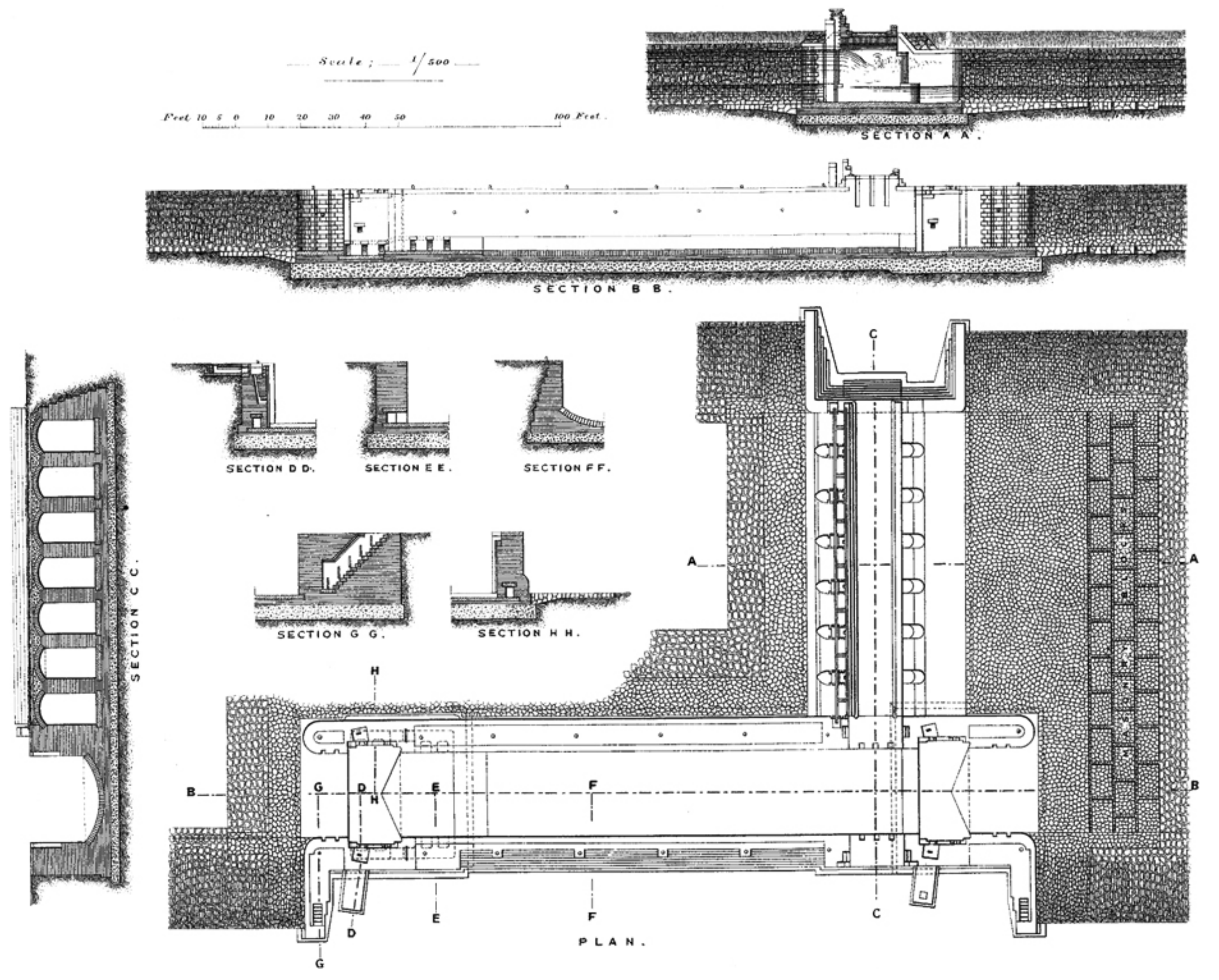
- Mohamed, E.K.; Khalil, E. Innovative solution for the repair of hydraulic structures (regulators). Water Sci. 2018, 32, 179–191. [Google Scholar] [CrossRef] [Green Version]
- Dalgleish, G.S. The Sanayta lock and bride-regulator (Including plate at back of volume). In Minutes of the Proceedings of the Institution of Civil Engineers; ICE Publishing: Washington, DC, USA, 1901. [Google Scholar]


| Building | Monument Registration Number | Period | Type | Usage | Condition | Characteristics of Multiple Leaf Masonry Walls | ||||||||
|---|---|---|---|---|---|---|---|---|---|---|---|---|---|---|
| Structure Material | Wall Thickness | Width of Leaves | Leaves Ratio | Slenderness Ration (λ) | Core Ratio % | |||||||||
| From | to | ext. | int. | int./ext. | int./W. | |||||||||
| Bab Zuwayla | 199 | Fatimid (AD 969–1171) | Military | Gate | V. good | Limestone, lime-based mortar, rubble infill | 1.2 | 5 | 0.20–0.25 | 1–4.6 | 5–20 | 3.5–10.0 | 83.3 | 92.0 |
| Masjid al-Salih Tala’i’ | 116 | Religious | Masjid | Good | Limestone, lime-based mortar, rubble infill | 1 | 1.4 | 0.20–0.25 | 0.8–1 | 4–5 | 7.8–11 | 80.0 | 71.4 | |
| Bab al-Mahruq | 307 | Ayyubid (AD 1171–1250) | Military | Tower | V. good | Limestone, lime-based mortar, rubble infill | 0.8 | 2.5 | 0.20–0.25 | 0.4–2 | 2–8 | 4.7–8.0 | 50.0 | 80.0 |
| North-eastern part of historic Cairo wall (Burj al-Zafar) | 307 | Military | Tower | Fair | Limestone, lime-based mortar, rubble infill | 0.6 | 4.1 | 0.20–0.25 | 0.2–3.6 | 1.0–15 | 3.0–8.0 | 33.3 | 87.8 | |
| Qubba al-Imam al-Shafi’i | 281 | Funerary | Mausoleum | Fair | Limestone, lime-based mortar, rubble infill | 2.6 | 2.8 | 0.23–0.25 | 1.1–2.3 | 8.4–10 | 3.57–3.94 | 42.3 | 82.1 | |
| Qasr al-Nassir Muhammad | 549 | Bahri Mamluk (AD 1250–1382) | Palatial | Palace | Ruins | Limestone, bricks, lime-based mortar, rubble infill | 0.7 | 1.95 | 0.20–0.25 | 0.2–1.6 | 1.5–6.5 | 4.0–6.5 | 28.6 | 82.1 |
| Khanqat Khawand Umm Anuk | 81 | Funerary | Mausoleum | Ruins | Limestone, bricks, lime-based mortar, rubble infill | 1 | 3 | 0.20–0.25 | 0.6–2.5 | 3–10 | 3.0–4.5 | 60.0 | 83.3 | |
| Complex of Baybars al-Jashankir | 32 | Religious, Funerary | Mausoleum, Khanqah | Fair | Limestone, lime-based mortar, rubble infill | 1 | 3.3 | 0.20–0.25 | 0.6–2.8 | 3–11.5 | 4.0–12.0 | 60.0 | 84.9 | |
| Complex of Al-Sultan Hasan | 133 | Religious, Educational, Funerary | Masjid, Madrasa, Mausoleum | V. good | Limestone, lime-based mortar, rubble infill | 1.2 | 5 | 0.20–0.30 | 0.8–4.5 | 4–18 | 6.5–20.5 | 66.7 | 90.0 | |
| Qubba Al-Ashraf Khalil ibn Qalawun | 275 | Funerary | Mausoleum | Good | Limestone, lime-based mortar, rubble infill | 1.4 | 1.9 | 0.20–0.25 | 1–1.4 | 5–7 | 5.3–7.2 | 71.4 | 73.7 | |
| Complex of Al- Sultan Qalawun | 43 | Educational, Healthcare, Religious | Masjid, Hospital, Madrasa | V. good | Limestone, lime-based mortar, rubble infill | 1.2 | 4.8 | 0.20–0.30 | 0.8–4.3 | 4–21 | 4.0–10.5 | 66.7 | 89.6 | |
| Qubba Yunus al-Dawadar | 139 | Funerary | Mausoleum | Ruins | Limestone, lime-based mortar, rubble infill | 0.7 | 1.2 | 0.20–0.25 | 0.3–0.8 | 1.5–4 | – | 42.9 | 66.7 | |
| Qasr al-Amir Qawsun | 266 | Palatial | Palace | Ruins | Limestone, bricks, lime-based mortar, rubble infill | 1.1 | 4.4 | 0.20–0.35 | 0.4–2.2 | 2–8.5 | 4.0–11.0 | 36.4 | 50.0 | |
| Amir Alin Aq Palace | 249 | Palatial | Palace | Good | Limestone, bricks, lime-based mortar, rubble infill | 1.3 | 3 | 0.20–0.25 | 0.9–2.5 | 4.5–10 | 4.0–9.5 | 69.2 | 83.3 | |
| Maq’ad al-Amir Mamay al-Sayfi | 51 | Circassian Mamluk (AD 1382–1517) | Residential | Shelter | Good | Limestone, lime-based mortar, rubble infill | 0.6 | 1.8 | 0.20–0.25 | 0.2–1.4 | 1–7.0 | 10.0–30.0 | 33.3 | 77.8 |
| Qubba al-Amir Tarabay al-Sharifi | 255 | Funerary | Mausoleum | V. good | Limestone, lime-based mortar, rubble infill | 0.5 | 1.5 | 0.20–0.25 | 0.08–1.1 | 0.35–7.5 | 2.0–10.5 | 20.0 | 73.3 | |
| Wakala al-Sultan Qaytbay | 75 | Commercial | Wikala | Partially collapsed | Limestone, lime-based mortar, rubble infill | 0.7 | 1.7 | 0.20–0.25 | 0.3–1.2 | 1.5–5 | 2.5–6.5 | 42.9 | 70.6 | |
| Complex of Sultan al-Ashraf Barsbay | 121 | Religious, Educational, Funerary | Khanqah, Madrasa, Mausoleum | Ruins | Limestone, lime-based mortar, rubble infill | 0.6 | 1.8 | 0.20–0.30 | 0.2–1.4 | 1–7 | 6.0–8.0 | 33.3 | 77.8 | |
| Complex of Sultan al-Ashraf Barsbay | 175 | Religious, Educational, Funerary, Waterworks | Masjid, Madrasa, Mausoleum, Sabil | Fair | Limestone, lime-based mortar, rubble infill | 0.9 | 3.9 | 0.20–0.25 | 0.5–3.4 | 2–13.5 | 3.5–13.0 | 55.6 | 87.2 | |
| Complex of Sultan al-Ashraf Inal | 158 | Religious, Educational, Funerary | Masjid, Madrasa, Mausoleum | Partially collapsed | Limestone, lime-based mortar, rubble infill | 0.4 | 1.6 | 0.20–0.25 | 0.08–1.2 | 0.5–6.0 | 6.0–10.0 | 25.0 | 75.0 | |
| The aqueduct (Majra Al-‘Uyun) | 78 | Waterworks | Aqueduct | Fair | Limestone, lime-based mortar, rubble infill | 2.9 | 3 | 0.25–0.35 | 2.3–2.5 | 7.5–10 | 4.5–6.2 | 79.3 | 83.3 | |
| Bab Qaytbay | 278 | Military | Gate | Partially collapsed | Limestone, lime-based mortar, rubble infill | 0.7 | 6.75 | 0.20–0.30 | 0.3–6.25 | 12.5–25 | 1.0–4.0 | 42.9 | 92.6 | |
| Masjid Bardbak (Umm al-Ghulam) | 25 | Religious | Masjid | Fair | Limestone, lime-based mortar, rubble infill | 0.6 | 1.1 | 0.20–0.25 | 0.2–0.7 | 1–3.5 | 8.0–10.0 | 33.3 | 63.6 | |
| Complex of Sultan Qansuh al-Ghuri | 65–67 | Religious, Educational, Funerary | Masjid, Madrasa, Mausoleum | V. good | Limestone, bricks, lime-based mortar, rubble infill | 0.8 | 2 | 0.20–0.25 | 0.4–1.4 | 2–4.5 | 8.0–17.5 | 50.0 | 70.0 | |
| Complex of Sultan Qaytbay | 104 | Educational, Funerary, Waterworks | Madrasa, Mausoleum, Sabil | Ruins | Limestone, lime-based mortar, rubble infill | 0.6 | 1.6 | 0.20–0.25 | 0.2–1.1 | 1–4.5 | 6.0–13.5 | 33.3 | 68.8 | |
| Aydakin al-Bunduqdari | 146 | Funerary, Religious | Mausoleum, Khanqah | Poor | Limestone, lime-based mortar, rubble infill | 1.2 | 2.8 | 0.20–0.25 | 0.8–2.3 | 4–9.2 | 5.5–8.5 | 66.7 | 82.1 | |
| Complex of Sultan al-Mu’ayyad Shaykh | 190 | Religious, Educational, Funerary | Masjid, Madrasa, Mausoleum | Good | Limestone, lime-based mortar, rubble infill | 1.9 | 4.5 | 0.20–0.25 | 1.5–4 | 7.5–18 | 5.2–8.5 | 79.0 | 88.9 | |
| Sabil Ibrahim Agha Mustahfizan | 238 | Ottoman (AD 1517–1867) | Waterworks | Sabil | Fair | Limestone, bricks, lime-based mortar, Gypsum mortar, rubble infill | 0.6 | 1.5 | 0.15–0.20 | 0.2–1 | 1–4 | 3.0–10.0 | 33.3 | 66.7 |
| Bab al-’Azab | 555 | Military | Tower | V. good | Limestone, lime-based mortar, rubble infill | 1.2 | 2.5 | 0.22–0.25 | 0.7–2 | 3.2–8 | 6.5–11.5 | 58.3 | 80.0 | |
| Bab of Ahmad Katkhuda | U93 | Military | Tower | Good | Limestone, lime-based mortar, rubble infill | 0.6 | 2.1 | 0.20–0.25 | 0.2–1.6 | 1–6.5 | 3.5–7.5 | 33.3 | 76.2 | |
| Saray Al-Musafir khana | 20 | Palatial | Palace | Ruins | Limestone, bricks, lime-based mortar, Gypsum mortar, rubble infill | 0.6 | 1.5 | 0.15–0.25 | 0.3–1.1 | 1–5.5 | 6.0–12.0 | 50.0 | 73.3 | |
| Takiyya Ibrahim al-Kulshani | 332 | Religious, Funerary | Mausoleum, Khanqah | Ruins | Limestone, lime-based mortar, rubble infill | 0.6 | 1.5 | 0.15–0.25 | 0.3–1 | 1–4 | 8.0–16.0 | 50.0 | 66.7 | |
| Zawiya of ‘All al-Maghrabi | U4 | AD 1866 | Religious | Zawiya | Ruins | Limestone, lime-based mortar, rubble infill | 0.8 | 1.1 | 0.15–0.20 | 0.5–0.8 | 2–2.5 | 6.0–11.5 | 62.5 | 72.7 |
Publisher’s Note: MDPI stays neutral with regard to jurisdictional claims in published maps and institutional affiliations. |
© 2021 by the authors. Licensee MDPI, Basel, Switzerland. This article is an open access article distributed under the terms and conditions of the Creative Commons Attribution (CC BY) license (https://creativecommons.org/licenses/by/4.0/).
Share and Cite
Amer, O.; Aita, D.; Mohamed, E.k.; Torky, A.; Shawky, A. Multi-Leaf Stone Masonry Walls in Egypt: A Legend. Heritage 2021, 4, 2763-2791. https://doi.org/10.3390/heritage4040156
Amer O, Aita D, Mohamed Ek, Torky A, Shawky A. Multi-Leaf Stone Masonry Walls in Egypt: A Legend. Heritage. 2021; 4(4):2763-2791. https://doi.org/10.3390/heritage4040156
Chicago/Turabian StyleAmer, Osama, Danila Aita, Ezzeldin k. Mohamed, Akram Torky, and Ashraf Shawky. 2021. "Multi-Leaf Stone Masonry Walls in Egypt: A Legend" Heritage 4, no. 4: 2763-2791. https://doi.org/10.3390/heritage4040156
APA StyleAmer, O., Aita, D., Mohamed, E. k., Torky, A., & Shawky, A. (2021). Multi-Leaf Stone Masonry Walls in Egypt: A Legend. Heritage, 4(4), 2763-2791. https://doi.org/10.3390/heritage4040156